EP0682548B1 - Toy riding apparatus - Google Patents
Toy riding apparatus Download PDFInfo
- Publication number
- EP0682548B1 EP0682548B1 EP94907374A EP94907374A EP0682548B1 EP 0682548 B1 EP0682548 B1 EP 0682548B1 EP 94907374 A EP94907374 A EP 94907374A EP 94907374 A EP94907374 A EP 94907374A EP 0682548 B1 EP0682548 B1 EP 0682548B1
- Authority
- EP
- European Patent Office
- Prior art keywords
- rider
- toy
- band
- riding apparatus
- support
- Prior art date
- Legal status (The legal status is an assumption and is not a legal conclusion. Google has not performed a legal analysis and makes no representation as to the accuracy of the status listed.)
- Expired - Lifetime
Links
- 239000000725 suspension Substances 0.000 claims abstract description 9
- 229920001971 elastomer Polymers 0.000 claims description 25
- 239000000806 elastomer Substances 0.000 claims description 7
- 239000004033 plastic Substances 0.000 claims description 7
- 235000019589 hardness Nutrition 0.000 description 3
- 230000006641 stabilisation Effects 0.000 description 3
- 238000011105 stabilization Methods 0.000 description 3
- 229920001875 Ebonite Polymers 0.000 description 1
- 241000283086 Equidae Species 0.000 description 1
- 241001559542 Hippocampus hippocampus Species 0.000 description 1
- 241001465754 Metazoa Species 0.000 description 1
- 210000002683 foot Anatomy 0.000 description 1
- 230000013011 mating Effects 0.000 description 1
- 239000002184 metal Substances 0.000 description 1
- 239000002991 molded plastic Substances 0.000 description 1
- 230000002035 prolonged effect Effects 0.000 description 1
- 210000003371 toe Anatomy 0.000 description 1
Images


Classifications
-
- A—HUMAN NECESSITIES
- A63—SPORTS; GAMES; AMUSEMENTS
- A63G—MERRY-GO-ROUNDS; SWINGS; ROCKING-HORSES; CHUTES; SWITCHBACKS; SIMILAR DEVICES FOR PUBLIC AMUSEMENT
- A63G13/00—Cradle swings; Rocking-horses; Like devices resting on the ground
- A63G13/06—Rocking-horses
- A63G13/08—Rocking-horses mounted on links or springs
Definitions
- the present invention relates to children's toys and amusement devices. More particularly, the present invention relates to toy riding devices such as rocking horses.
- U.S. Design Patent No. 290,474 to Tepper discloses an ornamental design for a rocking seahorse safety ring
- U.S. Design Patent No. 275,975 to Ciganko discloses an ornamental design for a rocking toy.
- the riding motion which is possible with the disclosed riding apparatuses is defined solely by rigid elements, such that the range of possible riding motion is restricted to one repeating path and the riding apparatuses are not as enjoyable to ride as apparatuses with more freedom of riding movement.
- U.S. Patent No. 2,937,691 to Horgan discloses a riding toy which includes a frame on which a simulated horse is mounted by means of four coil springs. The frame includes four uprights to which the springs are connected.
- U.S. Patent No. 2,756,051 to Shone discloses a hobby horse which includes a base made of hollow tubing and a carriage which is connected to the base by four coil springs.
- U.S. Patent No. 3,155,390 to Moore, et al. discloses a hobby horse which includes a frame having four uprights, and a horse which is connected to the frame by means of four coil springs.
- 3,093,356 to Buyalos, Jr. discloses a hobby horse base which includes four uprights which support a hobby horse through four laterally protruding pins and four heavy duty coil springs. Suction cups are used to anchor the hobby horse base to the floor.
- U.S. Design Patent No. 165,491 discloses an ornamental design for a hobby horse.
- U.S. Patent No. 2,971,758 to Zimmers discloses a rotatable rocking toy which includes a body of a horse to which are secured transverse support members, a rotatable upper frame having upwardly diverging legs, and coil springs hooked to the support members and the legs.
- U.S. Patent No. 2,915,312 to Barthel discloses a hobby horse having a base, end supports, a hollow horse's body mounted on spaced longitudinal bars, and springs secured to the end supports and the longitudinal bars.
- U.S. Patent No. 2,882,050 to Deady discloses a resiliently supported rider-actuated apparatus which includes a hobby horse, bolts connected to the hobby horse, and springs which are connected between the bolts and two pairs of standards.
- U.S. Patent No. 3,180,640 to Lawrence discloses a revolving rocking horse which includes a molded horse body having a post extending downwardly therefrom to a pair of spring brackets, and springs which interconnect the outer apices of the spring brackets to upturned ends of a frame.
- All of these riding or rocking toys utilize coil springs to connect a rocking horse or hobby horse to a base or frame and keep it suspended therefrom, and they thus all allow to at least some extent a greater freedom of riding motion than the rocking toys of the Tepper and Ciganko design patents.
- the addition of coil springs to riding and rocking toys has also added disadvantages to the toys.
- the coils of a coil spring naturally become spaced apart when the ends of the coil spring are pulled apart, i.e., when the coil spring is tensioned, and then quickly return to positions immediately adjacent one another when the ends thereof move back towards one another, i.e., when tension is released.
- coil springs in a riding or rocking toy make it easy for a child's fingers or toes to be pinched between adjacent coils of a coil spring.
- the coil springs are made of metal, they tend to squeak after they have been used for a period of time, which can make riding the toy a less desirable experience.
- the use of coil springs is also disadvantageous because coil springs tend to plastically deform relatively easily when they are subjected to prolonged cyclical stress, which can contribute to a ride which includes too much freedom of movement and thus feels unnatural.
- U.S. Patent No. 2,862,710 to Lewis discloses a rocking and swinging toy that includes a base (11), and an upstanding post (20) having a ball (21) thereon in engagement with a socket member (19) mounted to the base (11).
- a platform (22) is mounted to the post (20), and above the platform (22) is mounted a support member (41) that is adapted to support a child (49).
- Connected between the base (11) and the platform (22) are a plurality of elastic cables (18).
- the post (20) acts to support the platform (22) and the support member (41) above the base (11).
- the platform 22 can tilt due to the ball (21) and socket member (19) engagement, and the elastic cables (18) act to resist tilting and to bring the platform (22) back to an upright position.
- Such a toy is inherently much more dangerous, especially for very young children, than is a toy riding apparatus wherein a rider bearing means is suspended from support means of a base means.
- the child support member (41) of the Lewis patent is designed to include an unstable, tiltable support, i.e., the post (20), that can allow the child support member (41) to tilt to a position drastically angled relative to the base (11), and then to have a resistance force of the elastic cables (18) pull the child support member (41) back.
- Such drastic tilting motion can present far greater chances that a small child will fall off of the toy or injure his neck during sudden changes in tilting motion than the rocking motion of a suspended rider bearing means appears likely to present.
- a further object of the present invention is to provide a toy riding apparatus which presents a relatively reduced opportunity for a rider to be pinched by the apparatus.
- Another object of the present invention is to provide a toy riding apparatus which maintains a ride having a relatively natural feel over time.
- a toy riding apparatus which includes rider bearing means for bearing a rider during a riding motion, base means including support means extending upwardly from the base means for supporting the rider bearing means, and suspension means for suspending the rider bearing means from the support means.
- the suspension means includes a plurality of elastomeric band means which are connected between the rider bearing means and the support means.
- a toy riding apparatus 10 in accordance with an embodiment of the present invention includes a base 12 made up of two side pieces 14 and two braces 16, all of which are made of blow-molded plastic.
- Each of the side pieces 14 include two support posts 18 which extend upwardly therefrom, and an integral step 20.
- each of the side pieces 14 includes two female connectors 22 which mate with male connectors 24 of the braces 16.
- Each female connector 22 includes a connection slot 26 into which protrudes two upper retaining tabs 28, 30 and a lower retaining tab 32.
- the connection slot 26 thus includes an upper section 34, a middle section 36, and a lower section 38.
- each of the braces 16 includes on each end thereof an aforementioned male connector 24 and a stabilization extension 40.
- Each male connector 24 includes a hook 42 on the lower end thereof, a thin extension piece 44 extending from upwardly from the hook 42, and a pair of retaining pieces 46, 48 extending away from the extension piece 44, as shown in Figs. 1 and 3.
- the extension piece 44 includes a lower section 50 which extends between the hook 42 and the retaining pieces 46, 48, and an upper section 52 which extends between the brace 16 and the retaining pieces 46, 48.
- the base 12 is assembled by connecting two side pieces 14 to two braces 16 as shown in Fig. 1. Specifically, each brace 16 is connected to each side piece 14 in the following manner.
- the male connector 24 of a brace 16 is aligned with a female connector 22 of a side piece 14 such that the hook 42 is immediately behind the lower section 38 of the connecting slot 26, the lower section 50 of the extension piece 44 is immediately behind the middle section 36 of the connecting slot 26, and the retaining pieces 46, 48 are immediately behind the upper section 34 of the connecting slot 26.
- the male connector 24 is then slid into the female connector 22 until the stabilization extension 40 contacts the side piece 14.
- the brace 16 is then moved downwardly until a top edge 33 of the lower retaining tab 32 contacts a lower inside edge 25 of the male connector 24, at which point the lower retaining tab 32 rests behind the hook 42 and the upper retaining tabs 28, 30 rest behind the retaining pieces 46, 48.
- the stabilization extension 40 then rests against the side piece 14 to held stabilize the connection between the side piece 14 and the brace 16.
- a small hook 54 on the brace 16 cooperates with a mating hook (not shown) on the side piece 14 to deter the brace 16 from accidentally moving upwardly relative to the side piece 14, and thus reduces the chance that the side piece 14 and the brace 16 will become accidentally disconnected.
- the toy riding apparatus 10 further includes a rider support device or bearing means 60 which is preferably formed in the shape of a horse.
- the rider support device 60 includes a body 62 which is roto-molded out of plastic, and a saddle 64 which is separately roto-molded out of plastic and then fastened to the body 62 by fasteners 66.
- the saddle 64 has a thinner wall thickness than the body 62, and it is consequently more deformable. The saddle 64 thus feels softer, and it therefore is more comfortable for a rider.
- the toy riding apparatus 10 also includes four elastomeric suspension bands 70 (three shown) which are connected between the rider support device 60 and the support posts 18 of the base 12 to suspend the rider support device 60 from the support posts 18.
- elastomeric suspension bands 70 is shown in Figs. 4-8.
- the band 70 is made of an elastomer, and includes two retaining sections or rotatable connecting means 72, 74 on either end thereof, which retaining sections 72, 74 are formed as right circular cylinders 76, 78 having right circular cylindrical holes 80, 82 therethrough.
- the band 70 is preferably made of co-molded rubber.
- the retaining sections 72, 74 are preferably molded out of a first type of rubber and the band sections 84, 86 and the web section 88 are preferably molded out of a second type of rubber, wherein the first type of rubber is harder than the second type of rubber.
- the first type of rubber is preferably a blended rubber having a hardness of about 90 shore "A” and the second type of rubber is preferably a blended rubber having a hardness of about 60 shore "A".
- the use of two types of rubber allows the band 70 to be made relatively stiff at the retaining sections 72, 74 to prevent elongation of the holes 80, 82 during use of the apparatus 10, and relatively more flexible at the band sections 84, 86 and the web section 88 to allow the band 70 to deliver a bouncy ride. Further, as seen in Fig. 8, in the direction defined by the axis A-A of the hole 80, the retaining section 72 (and consequently retaining section 74) is thicker than the band sections 84, 86, which are in turn thicker than the web section 88.
- the relative thickness of the retaining sections 72, 74 helps to increase the rigidity of the retaining sections 72, 74, and the relative thinness of the band sections 84, 86 increases their flexibility so they can deliver a more bouncy ride while still maintaining enough rigidity to support the weight of a child.
- the web section 88 is the thinnest of the sections, and is provided to prevent a child's hand or foot from being caught between the band sections 84, 86.
- the rider support device 60 has four support device pins 90 (two shown) attached thereto at spaced locations on the body 62 such that the pins 90 extend generally horizontally from the body 62.
- Each of the pins 90 extends through the hole 82 in the retaining section 74 of one of the bands 70 and the retaining section 74 is secured on the pin 90 by means of a cap 92 which is press fit, bolted, or otherwise attached to the pin 90.
- the retaining section 74 is thus able to rotate around the pin 90, and each of the bands 70 is thus rotatably connected to the rider support device 60.
- the toy riding apparatus 10 further includes four support post pins 94, as seen in Figs. 1 and 9.
- Each of the support posts 18 have a plurality of vertically spaced holes 96 therethrough, and each of the pins 94 extends into one of the holes 96 in one of the support posts 18, such that each support post 18 has one pin 94 extending therein.
- the plurality of holes 96 are provided in each support post 18 to act as means for adjusting the height at which the rider support device 60 will be suspended.
- each pin 94 extends through the hole 80 in the retaining section 72 of one of the bands 70, and secures the band 70 on the pin 94 by means of a flange 98 and a bolt 100 which fastens the pin 94 to the support post 18.
- the retaining section 72 is able to rotate on the pin 94, and each of bands 70 is thus rotatably connected to one of the support posts 18.
- the base 12 of the toy riding apparatus 10 is assembled as detailed above, and the pins 94 are placed through the holes 80 in the retaining sections 72, and are secured in the holes 96 which are at a desired vertical height.
- the bands 70 are then connected to the pins 90 such that the rider support device 60 is elastically suspended from the support posts 18 by the bands 70.
- the saddle 64 has a thinner wall thickness than the body 62 of the rider support device 60, and is thus made more comfortable for the child.
- the child can then proceed to "ride" the toy riding apparatus 10, which involves shifting his or her weight on the rider support device 60.
- the load supported by each of the bands 70 varies, and thus the band sections 84, 86 and the web sections 88 elongate and shorten elastically in response to the varying load, and the bands 70 rotate relative to the rider support device 60 and the support posts 18 as the position of the rider support device 60 relative to each of the support posts 18 changes.
- each of the bands 70 are made of a relatively hard rubber, they will resist flexing and, thus, the holes 80, 82 through the retaining sections 72, 74 will resist elongation.
- the band sections 84, 86 and the web sections 88 since they are made of a softer rubber, will tend to elongate and shorten elastically with the varying load, but because they are made of an elastomer they will plastically deform relatively slowly so that the toy riding apparatus 10 will deliver a more natural feeling ride for a relatively long time.
- the bands 70 are made of an elastomer, use of the toy riding apparatus will produce relatively little squeaking, making for a relatively quieter ride.
- the use of elastomeric bands 70 greatly reduces the number of potential pinch points presented by the suspension of the toy riding apparatus, which helps to make the toy riding apparatus 10 relatively safer to ride.
- the rider support device 60 in other shapes than that of a horse.
- the rider support device 60 may be shaped as another type of animal, an automobile, an airplane, or a spaceship, among other things.
- three holes 96 are shown in each support post 18 in the drawing figures, more or fewer holes 96 may be provided to allow for larger or more precise adjustments in height, and advantages obtained therefrom.
- an elastomer other than a blended rubber to be used in the bands 70, for only one type of rubber to be used in the bands 70, or for the two types of rubber used in the bands 70 to be made of different hardnesses than those disclosed.
- the saddle 64 and the body 62 of the rider support device 60 may be formed of the same thickness of plastic, and advantages obtained therefrom.
- Plastic parts which are disclosed as being blow molded may be roto-molded, and those which are disclosed as being roto-molded may be blow molded. It is also within the scope of the invention to form a second integral step near the bottom of each side piece 12. Further, it is to be understood that other means of securing the bands 70 to the rider support device 64 and the support posts 18 may be advantageously used.
Landscapes
- Toys (AREA)
Abstract
Description
- The present invention relates to children's toys and amusement devices. More particularly, the present invention relates to toy riding devices such as rocking horses.
- Many different types of rocking or riding toys have been developed for children. For example, U.S. Design Patent No. 290,474 to Tepper discloses an ornamental design for a rocking seahorse safety ring, and U.S. Design Patent No. 275,975 to Ciganko discloses an ornamental design for a rocking toy. In both the Tepper and the Ciganko design patents, however, the riding motion which is possible with the disclosed riding apparatuses is defined solely by rigid elements, such that the range of possible riding motion is restricted to one repeating path and the riding apparatuses are not as enjoyable to ride as apparatuses with more freedom of riding movement.
- Other rocking or riding toys have been developed which allow a rider more freedom of movement. For example, U.S. Patent No. 2,937,691 to Horgan discloses a riding toy which includes a frame on which a simulated horse is mounted by means of four coil springs. The frame includes four uprights to which the springs are connected. U.S. Patent No. 2,756,051 to Shone discloses a hobby horse which includes a base made of hollow tubing and a carriage which is connected to the base by four coil springs. U.S. Patent No. 3,155,390 to Moore, et al. discloses a hobby horse which includes a frame having four uprights, and a horse which is connected to the frame by means of four coil springs. U.S. Patent No. 3,093,356 to Buyalos, Jr. discloses a hobby horse base which includes four uprights which support a hobby horse through four laterally protruding pins and four heavy duty coil springs. Suction cups are used to anchor the hobby horse base to the floor. U.S. Design Patent No. 165,491 discloses an ornamental design for a hobby horse.
- U.S. Patent No. 2,971,758 to Zimmers discloses a rotatable rocking toy which includes a body of a horse to which are secured transverse support members, a rotatable upper frame having upwardly diverging legs, and coil springs hooked to the support members and the legs. U.S. Patent No. 2,915,312 to Barthel discloses a hobby horse having a base, end supports, a hollow horse's body mounted on spaced longitudinal bars, and springs secured to the end supports and the longitudinal bars. Also, U.S. Patent No. 2,882,050 to Deady discloses a resiliently supported rider-actuated apparatus which includes a hobby horse, bolts connected to the hobby horse, and springs which are connected between the bolts and two pairs of standards. U.S. Patent No. 3,180,640 to Lawrence discloses a revolving rocking horse which includes a molded horse body having a post extending downwardly therefrom to a pair of spring brackets, and springs which interconnect the outer apices of the spring brackets to upturned ends of a frame.
- All of these riding or rocking toys utilize coil springs to connect a rocking horse or hobby horse to a base or frame and keep it suspended therefrom, and they thus all allow to at least some extent a greater freedom of riding motion than the rocking toys of the Tepper and Ciganko design patents. However, the addition of coil springs to riding and rocking toys has also added disadvantages to the toys. The coils of a coil spring naturally become spaced apart when the ends of the coil spring are pulled apart, i.e., when the coil spring is tensioned, and then quickly return to positions immediately adjacent one another when the ends thereof move back towards one another, i.e., when tension is released. Accordingly, the use of coil springs in a riding or rocking toy make it easy for a child's fingers or toes to be pinched between adjacent coils of a coil spring. In addition, since the coil springs are made of metal, they tend to squeak after they have been used for a period of time, which can make riding the toy a less desirable experience. The use of coil springs is also disadvantageous because coil springs tend to plastically deform relatively easily when they are subjected to prolonged cyclical stress, which can contribute to a ride which includes too much freedom of movement and thus feels unnatural.
- A different type of toy is disclosed in U.S. Patent No. 2,862,710 to Lewis (the "Lewis patent"), which discloses a rocking and swinging toy that includes a base (11), and an upstanding post (20) having a ball (21) thereon in engagement with a socket member (19) mounted to the base (11). A platform (22) is mounted to the post (20), and above the platform (22) is mounted a support member (41) that is adapted to support a child (49). Connected between the base (11) and the platform (22) are a plurality of elastic cables (18).
- As seen in Figs. 3 and 5, the post (20) acts to support the platform (22) and the support member (41) above the base (11). As stated in column 4, lines 42-50 of the Lewis patent, the
platform 22 can tilt due to the ball (21) and socket member (19) engagement, and the elastic cables (18) act to resist tilting and to bring the platform (22) back to an upright position. Such a toy is inherently much more dangerous, especially for very young children, than is a toy riding apparatus wherein a rider bearing means is suspended from support means of a base means. The child support member (41) of the Lewis patent is designed to include an unstable, tiltable support, i.e., the post (20), that can allow the child support member (41) to tilt to a position drastically angled relative to the base (11), and then to have a resistance force of the elastic cables (18) pull the child support member (41) back. Such drastic tilting motion can present far greater chances that a small child will fall off of the toy or injure his neck during sudden changes in tilting motion than the rocking motion of a suspended rider bearing means appears likely to present. - In view of the above, it is an object of the present invention to provide an improved toy riding apparatus which is readily capable of being ridden by a child.
- It is another object of the present invention to provide a toy riding apparatus which provides an extended range of riding motion.
- A further object of the present invention is to provide a toy riding apparatus which presents a relatively reduced opportunity for a rider to be pinched by the apparatus.
- It is a further object of the present invention to provide a toy riding apparatus which maintains a relatively quiet ride over time.
- Another object of the present invention is to provide a toy riding apparatus which maintains a ride having a relatively natural feel over time.
- The objects of the invention are accomplished by a toy riding apparatus which includes rider bearing means for bearing a rider during a riding motion, base means including support means extending upwardly from the base means for supporting the rider bearing means, and suspension means for suspending the rider bearing means from the support means. The suspension means includes a plurality of elastomeric band means which are connected between the rider bearing means and the support means.
- The preferred embodiment of the present invention will be described in greater detail with reference to the accompanying drawings, wherein like members bear like reference numerals and wherein:
- Fig. 1 is a perspective view of the toy riding apparatus of the present invention;
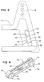
- Fig. 2 is a front view of a portion of a side piece of a base of the toy riding apparatus of Fig. 1;
- Fig. 3 is a back view of a portion of a brace of the base of the toy riding apparatus of Fig. 1;
- Fig. 4 is a perspective view of an elastomeric suspension band of the toy riding apparatus of Fig. 1;
- Fig. 5 is a front view of the band of Fig. 4;
- Fig. 6 is a top view of the band of Fig. 4;
- Fig. 7 is an end view of the band of Fig. 4;
- Fig. 8 is cross sectional view along line VIII-VIII of Fig. 5; and
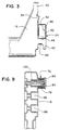
- Fig. 9 is a sectional view of a connection between the band and the base of the toy riding apparatus of Fig. 1.
- With reference to Figs. 1-9, a
toy riding apparatus 10 in accordance with an embodiment of the present invention includes abase 12 made up of twoside pieces 14 and twobraces 16, all of which are made of blow-molded plastic. Each of theside pieces 14 include twosupport posts 18 which extend upwardly therefrom, and anintegral step 20. - As can be seen from Fig. 1 and from Fig. 2, which shows an end portion of one of the side pieces 14 (the opposite end portion being a mirror image of Fig. 2), each of the
side pieces 14 includes twofemale connectors 22 which mate withmale connectors 24 of thebraces 16. Eachfemale connector 22 includes aconnection slot 26 into which protrudes twoupper retaining tabs lower retaining tab 32. Theconnection slot 26 thus includes anupper section 34, amiddle section 36, and alower section 38. - As can be seen from Fig. 3, which shows an end portion of one of the braces 16 (the opposite end portion being a mirror image of Fig. 3), each of the
braces 16 includes on each end thereof anaforementioned male connector 24 and astabilization extension 40. Eachmale connector 24 includes ahook 42 on the lower end thereof, athin extension piece 44 extending from upwardly from thehook 42, and a pair ofretaining pieces extension piece 44, as shown in Figs. 1 and 3. Theextension piece 44 includes alower section 50 which extends between thehook 42 and theretaining pieces upper section 52 which extends between thebrace 16 and theretaining pieces - The
base 12 is assembled by connecting twoside pieces 14 to twobraces 16 as shown in Fig. 1. Specifically, eachbrace 16 is connected to eachside piece 14 in the following manner. Themale connector 24 of abrace 16 is aligned with afemale connector 22 of aside piece 14 such that thehook 42 is immediately behind thelower section 38 of the connectingslot 26, thelower section 50 of theextension piece 44 is immediately behind themiddle section 36 of the connectingslot 26, and theretaining pieces upper section 34 of the connectingslot 26. Themale connector 24 is then slid into thefemale connector 22 until thestabilization extension 40 contacts theside piece 14. Thebrace 16 is then moved downwardly until atop edge 33 of thelower retaining tab 32 contacts a lowerinside edge 25 of themale connector 24, at which point thelower retaining tab 32 rests behind thehook 42 and theupper retaining tabs pieces stabilization extension 40 then rests against theside piece 14 to held stabilize the connection between theside piece 14 and thebrace 16. Asmall hook 54 on thebrace 16 cooperates with a mating hook (not shown) on theside piece 14 to deter thebrace 16 from accidentally moving upwardly relative to theside piece 14, and thus reduces the chance that theside piece 14 and thebrace 16 will become accidentally disconnected. - As shown in Fig. 1, the
toy riding apparatus 10 further includes a rider support device or bearing means 60 which is preferably formed in the shape of a horse. Therider support device 60 includes abody 62 which is roto-molded out of plastic, and asaddle 64 which is separately roto-molded out of plastic and then fastened to thebody 62 byfasteners 66. Thesaddle 64 has a thinner wall thickness than thebody 62, and it is consequently more deformable. Thesaddle 64 thus feels softer, and it therefore is more comfortable for a rider. - As shown in Fig. 1, the
toy riding apparatus 10 also includes four elastomeric suspension bands 70 (three shown) which are connected between therider support device 60 and the support posts 18 of the base 12 to suspend therider support device 60 from the support posts 18. One of theelastomeric suspension bands 70 is shown in Figs. 4-8. Theband 70 is made of an elastomer, and includes two retaining sections orrotatable connecting means sections circular cylinders cylindrical holes sections band sections web section 88 extending between the retainingsections band sections - The
band 70 is preferably made of co-molded rubber. Specifically, the retainingsections band sections web section 88 are preferably molded out of a second type of rubber, wherein the first type of rubber is harder than the second type of rubber. The first type of rubber is preferably a blended rubber having a hardness of about 90 shore "A" and the second type of rubber is preferably a blended rubber having a hardness of about 60 shore "A". The use of two types of rubber allows theband 70 to be made relatively stiff at the retainingsections holes apparatus 10, and relatively more flexible at theband sections web section 88 to allow theband 70 to deliver a bouncy ride. Further, as seen in Fig. 8, in the direction defined by the axis A-A of thehole 80, the retaining section 72 (and consequently retaining section 74) is thicker than theband sections web section 88. The relative thickness of the retainingsections sections band sections web section 88 is the thinnest of the sections, and is provided to prevent a child's hand or foot from being caught between theband sections - As seen in Fig. 1, the
rider support device 60 has four support device pins 90 (two shown) attached thereto at spaced locations on thebody 62 such that thepins 90 extend generally horizontally from thebody 62. Each of thepins 90 extends through thehole 82 in the retainingsection 74 of one of thebands 70 and the retainingsection 74 is secured on thepin 90 by means of acap 92 which is press fit, bolted, or otherwise attached to thepin 90. The retainingsection 74 is thus able to rotate around thepin 90, and each of thebands 70 is thus rotatably connected to therider support device 60. - The
toy riding apparatus 10 further includes four support post pins 94, as seen in Figs. 1 and 9. Each of the support posts 18 have a plurality of vertically spacedholes 96 therethrough, and each of thepins 94 extends into one of theholes 96 in one of the support posts 18, such that eachsupport post 18 has onepin 94 extending therein. The plurality ofholes 96 are provided in eachsupport post 18 to act as means for adjusting the height at which therider support device 60 will be suspended. As shown in Fig. 9, eachpin 94 extends through thehole 80 in the retainingsection 72 of one of thebands 70, and secures theband 70 on thepin 94 by means of aflange 98 and abolt 100 which fastens thepin 94 to thesupport post 18. The retainingsection 72 is able to rotate on thepin 94, and each ofbands 70 is thus rotatably connected to one of the support posts 18. - With reference to Figs. 1-9, the structure and operation of the
toy riding apparatus 10 will now be explained. Thebase 12 of thetoy riding apparatus 10 is assembled as detailed above, and thepins 94 are placed through theholes 80 in the retainingsections 72, and are secured in theholes 96 which are at a desired vertical height. Thebands 70 are then connected to thepins 90 such that therider support device 60 is elastically suspended from the support posts 18 by thebands 70. Once thetoy riding apparatus 10 is in this assembled state, shown in Fig. 1, a child can mount therider support device 60, using theintegral step 20 if necessary, and sit in thesaddle 64. As stated above, thesaddle 64 has a thinner wall thickness than thebody 62 of therider support device 60, and is thus made more comfortable for the child. The child can then proceed to "ride" thetoy riding apparatus 10, which involves shifting his or her weight on therider support device 60. As the child's weight shifts, the load supported by each of thebands 70 varies, and thus theband sections web sections 88 elongate and shorten elastically in response to the varying load, and thebands 70 rotate relative to therider support device 60 and the support posts 18 as the position of therider support device 60 relative to each of the support posts 18 changes. - Because the retaining
sections bands 70 are made of a relatively hard rubber, they will resist flexing and, thus, theholes sections band sections web sections 88, since they are made of a softer rubber, will tend to elongate and shorten elastically with the varying load, but because they are made of an elastomer they will plastically deform relatively slowly so that thetoy riding apparatus 10 will deliver a more natural feeling ride for a relatively long time. In addition, because thebands 70 are made of an elastomer, use of the toy riding apparatus will produce relatively little squeaking, making for a relatively quieter ride. Most importantly, however, the use ofelastomeric bands 70 greatly reduces the number of potential pinch points presented by the suspension of the toy riding apparatus, which helps to make thetoy riding apparatus 10 relatively safer to ride. - It is to be appreciated that, while not shown in the drawings, it is within the scope of the invention to form the
rider support device 60 in other shapes than that of a horse. For instance, therider support device 60 may be shaped as another type of animal, an automobile, an airplane, or a spaceship, among other things. Also, although threeholes 96 are shown in eachsupport post 18 in the drawing figures, more orfewer holes 96 may be provided to allow for larger or more precise adjustments in height, and advantages obtained therefrom. It is further within the scope of the invention for an elastomer other than a blended rubber to be used in thebands 70, for only one type of rubber to be used in thebands 70, or for the two types of rubber used in thebands 70 to be made of different hardnesses than those disclosed. Thesaddle 64 and thebody 62 of therider support device 60 may be formed of the same thickness of plastic, and advantages obtained therefrom. - Plastic parts which are disclosed as being blow molded may be roto-molded, and those which are disclosed as being roto-molded may be blow molded. It is also within the scope of the invention to form a second integral step near the bottom of each
side piece 12. Further, it is to be understood that other means of securing thebands 70 to therider support device 64 and the support posts 18 may be advantageously used. - The principles, a preferred embodiment and the mode of operation of the present invention have been described in the foregoing specification. However, the invention which is intended to be protected is not to be construed as limited to the particular embodiment disclosed. The embodiment is therefore to be regarded as illustrative rather than restrictive. Variations and changes may be made by others without departing from the spirit of the present invention. Accordingly, it is expressly intended that all such equivalents, variations and changes which fall within the scope of the present invention as defined in the claims be embraced thereby.
Claims (8)
- A toy riding apparatus (10) including rider bearing means (60) for bearing a rider during a riding motion, base means (12) that includes support means (18) extending upwardly from said base means (12) for supporting said rider bearing means (60), and suspension means for suspending said rider bearing means (60) from said support means (18), characterized in that said suspension means includes a plurality of elastomeric band means (70) that are connected between said rider bearing means (60) and said support means (18).
- A toy riding apparatus (10) as claimed in claim 1, wherein each of said band means (70) includes first and second rotatable connecting means (72, 74) for rotatably connecting said band means (70) to said rider bearing means (60) and said support means (18), respectively, and elastic flexing means (84, 86, 88) for elastically flexing as said rider bearing means (60) is ridden, said elastic flexing means (84, 86, 88) being made of an elastomer and extending between said first and second connecting means (72, 74).
- A toy riding apparatus (10) as claimed in claim 2, wherein said flexing means (84, 86, 88) includes a pair of spaced band sections (84, 86) that are made of an elastomer and that extend between said first and second connecting means (72, 74), and a web section (88) that is made of an elastomer and that extends between said first and second connecting means (72, 74) and said band sections (84, 86).
- A toy riding apparatus (10) as claimed in claim 2, wherein said first and second connecting means (72, 74) are made of a first type of rubber and said flexing means (84, 86, 88) is made of a second type of rubber, said first type of rubber being harder than said second type of rubber.
- A toy riding apparatus (10) as claimed in claim 1, wherein said rider bearing means (60) has attached thereto a plurality of first pin means (90), said support means (18) has attached thereto a plurality of second pin means (94), and each of said band means (70) includes first and second rotatable connecting means (72, 74) for rotatably connecting said band means (70) to one of said first pin means (90) and one of said second pin means (94), respectively.
- A toy riding apparatus (10) as claimed in claim 1, wherein said support means (18) includes means (96) for adjusting the height at which said rider bearing device (60) is supported by said support means (18).
- A toy riding apparatus (10) as claimed in claim 1, wherein said base means (12) is made of plastic and includes step means (20) for stepping thereon and mounting the rider bearing device (60).
- A toy riding apparatus (10) as claimed in claim 1, wherein said rider bearing means (60) includes a body (62) made of plastic and a saddle (64) made of plastic, said saddle (64) having a thinner wall thickness than said body (62).
Applications Claiming Priority (3)
| Application Number | Priority Date | Filing Date | Title |
|---|---|---|---|
| US08/014,373 US5328410A (en) | 1993-02-05 | 1993-02-05 | Toy riding apparatus |
| PCT/US1994/001073 WO1994017884A1 (en) | 1993-02-05 | 1994-01-27 | Toy riding apparatus |
| US14373 | 2001-11-09 |
Publications (2)
| Publication Number | Publication Date |
|---|---|
| EP0682548A1 EP0682548A1 (en) | 1995-11-22 |
| EP0682548B1 true EP0682548B1 (en) | 1997-05-02 |
Family
ID=21765090
Family Applications (1)
| Application Number | Title | Priority Date | Filing Date |
|---|---|---|---|
| EP94907374A Expired - Lifetime EP0682548B1 (en) | 1993-02-05 | 1994-01-27 | Toy riding apparatus |
Country Status (4)
| Country | Link |
|---|---|
| US (1) | US5328410A (en) |
| EP (1) | EP0682548B1 (en) |
| AU (1) | AU6098894A (en) |
| WO (1) | WO1994017884A1 (en) |
Families Citing this family (29)
| Publication number | Priority date | Publication date | Assignee | Title |
|---|---|---|---|---|
| DE4328473C2 (en) * | 1993-08-24 | 1997-05-28 | Rainer H Heubl | Rocking device |
| US5645489A (en) * | 1995-06-07 | 1997-07-08 | Roadmaster Corporation | Hobby horse with protective sheath |
| US5690383A (en) * | 1996-03-07 | 1997-11-25 | Lisco Inc. | Baby bungee jumper |
| WO1999024132A1 (en) * | 1997-11-07 | 1999-05-20 | Sega Enterprises, Ltd. | Game machine |
| US6053816A (en) * | 1998-11-16 | 2000-04-25 | Cmi Rubber Company, Inc. | Single compound elastic band with embedded metallic coil reinforcement and toy riding apparatus incorporating same |
| US6416381B1 (en) | 2000-08-15 | 2002-07-09 | The Little Tikes Company | Motion induced sound and light generating system |
| USD485870S1 (en) | 2001-11-19 | 2004-01-27 | George P. Norman | Airplane shaped rocking apparatus |
| US6551164B1 (en) | 2002-05-06 | 2003-04-22 | Stephen J. Motosko | Toy horse with self-storable components thereof |
| US8267803B2 (en) | 2004-02-06 | 2012-09-18 | Mattel, Inc. | Reconfigurable infant support structure |
| US7727076B2 (en) | 2004-02-06 | 2010-06-01 | Mattel, Inc. | Free-standing jumping device |
| US7775893B2 (en) * | 2006-06-23 | 2010-08-17 | Moose Mountain Toymakers Ltd. | Children's riding device |
| US8021273B2 (en) * | 2007-09-11 | 2011-09-20 | Coreathletics Llc | Tumbler apparatus |
| USD591985S1 (en) * | 2008-02-12 | 2009-05-12 | General Kinematics Corporation | Rocker leg |
| USD598681S1 (en) * | 2008-08-19 | 2009-08-25 | General Kinematics Corporation | Rocker leg |
| USD675454S1 (en) | 2010-09-15 | 2013-02-05 | Kids Ii, Inc. | Infant jumper |
| USD650208S1 (en) | 2010-09-15 | 2011-12-13 | Kids Ii, Inc. | Infant jumper |
| USD650207S1 (en) | 2010-09-15 | 2011-12-13 | Kids Ii, Inc. | Infant jumper |
| USD697562S1 (en) | 2013-01-30 | 2014-01-14 | Ronald J. Milfeld | Stationary motorcycle toy |
| CN104884133B (en) | 2013-03-14 | 2018-02-23 | 艾肯运动与健康公司 | Force exercise equipment with flywheel |
| EP3974036B1 (en) | 2013-12-26 | 2024-06-19 | iFIT Inc. | Magnetic resistance mechanism in a cable machine |
| WO2015191445A1 (en) | 2014-06-09 | 2015-12-17 | Icon Health & Fitness, Inc. | Cable system incorporated into a treadmill |
| USD782744S1 (en) | 2014-06-23 | 2017-03-28 | Revision Military S.A.R.L. | Visor lens |
| US10940360B2 (en) | 2015-08-26 | 2021-03-09 | Icon Health & Fitness, Inc. | Strength exercise mechanisms |
| TWI644702B (en) | 2015-08-26 | 2018-12-21 | 美商愛康運動與健康公司 | Strength exercise mechanisms |
| US10293211B2 (en) | 2016-03-18 | 2019-05-21 | Icon Health & Fitness, Inc. | Coordinated weight selection |
| US10441840B2 (en) | 2016-03-18 | 2019-10-15 | Icon Health & Fitness, Inc. | Collapsible strength exercise machine |
| US10252109B2 (en) | 2016-05-13 | 2019-04-09 | Icon Health & Fitness, Inc. | Weight platform treadmill |
| US10661114B2 (en) | 2016-11-01 | 2020-05-26 | Icon Health & Fitness, Inc. | Body weight lift mechanism on treadmill |
| TWI648081B (en) | 2016-12-05 | 2019-01-21 | 美商愛康運動與健康公司 | Pull rope resistance mechanism in treadmill |
Family Cites Families (34)
| Publication number | Priority date | Publication date | Assignee | Title |
|---|---|---|---|---|
| US362941A (en) * | 1887-05-17 | Jesse a | ||
| US366571A (en) * | 1887-07-12 | Hobby-horse | ||
| US385792A (en) * | 1888-07-10 | oeandall | ||
| US2364081A (en) * | 1938-06-10 | 1944-12-05 | Lambert Gustaf Paul | Protective spring for boats and small craft |
| US2554045A (en) * | 1949-02-18 | 1951-05-22 | Jr Leo L Minor | Spring supported hobbyhorse |
| US2756051A (en) * | 1954-07-20 | 1956-07-24 | Samuel M Shone | Hobby horse |
| US2770291A (en) * | 1954-11-08 | 1956-11-13 | Forman Sidney | Hobbyhorses |
| US3037769A (en) * | 1956-01-31 | 1962-06-05 | William F Deady | Resiliently supported rider-actuated apparatus |
| US2882050A (en) * | 1956-01-31 | 1959-04-14 | William F Deady | Resiliently supported rider-actuated apparatus |
| US2862710A (en) * | 1956-12-31 | 1958-12-02 | John A Lewis | Rocking and swinging toy |
| US2919132A (en) * | 1957-03-29 | 1959-12-29 | William P Canady | Hobby horse foot step and stirrup |
| US2915312A (en) * | 1957-04-12 | 1959-12-01 | Charles E Barthel | Sound-producing mechanism for a child's amusement device |
| US2937691A (en) * | 1958-02-07 | 1960-05-24 | Moulded Products Inc | Riding toy |
| US2971758A (en) * | 1958-04-21 | 1961-02-14 | Edward J Zimmers | Rotatable rocking toy |
| US2921789A (en) * | 1958-05-22 | 1960-01-19 | Sr James L Skinner | Rocking horse |
| US2978245A (en) * | 1959-03-10 | 1961-04-04 | Rempel Mfg Inc | Toys |
| US3155390A (en) * | 1961-11-06 | 1964-11-03 | Moulded Products Inc | Hobby horse |
| US3093356A (en) * | 1962-03-23 | 1963-06-11 | Jr Michael A Buyalos | Hobby horse base |
| US3220726A (en) * | 1963-04-02 | 1965-11-30 | Wonder Products Company | Center post hobby horse |
| US3180640A (en) * | 1963-05-24 | 1965-04-27 | Donald K Lawrence | Revolving rocking horse |
| US4072309A (en) * | 1976-06-21 | 1978-02-07 | Wilson Jerry Lee | Multi-purpose exercise device |
| US4093208A (en) * | 1977-01-18 | 1978-06-06 | Roth American, Inc. | Child's riding toy and stand apparatus |
| USD256606S (en) | 1978-05-11 | 1980-08-26 | Tomar Corporation | Arrowhead remover |
| GB2075350B (en) * | 1980-05-09 | 1984-06-06 | Hirst B & Sons Ltd | Playground rocking apparatus |
| US4492375A (en) * | 1982-08-16 | 1985-01-08 | Contractor Equipment Manufacturers, Inc. | Resilient type exercising device with removable weights |
| USD275975S (en) | 1983-01-27 | 1984-10-16 | The Quaker Oats Company | Rocking toy |
| USD280224S (en) | 1983-02-15 | 1985-08-20 | Soloflex, Inc. | Variable resistance strap for exercise apparatus |
| US4582320A (en) * | 1984-09-21 | 1986-04-15 | Shaw James H | Exercise equipment |
| US4618144A (en) * | 1984-11-09 | 1986-10-21 | Gibson Christopher S | Portable exercise device |
| USD290474S (en) | 1985-05-24 | 1987-06-23 | Sidney Tepper | Combined rocking seahorse safety ring and detachable toy figures |
| US5135216A (en) * | 1991-01-29 | 1992-08-04 | Proform Fitness Products, Inc. | Modular resistance assembly for exercise machines |
| US4852874A (en) * | 1987-09-23 | 1989-08-01 | Advantage Entertainment, Inc. | Portable isokinetic exercising device |
| US4943046A (en) * | 1988-03-01 | 1990-07-24 | Sutcliffe Group Limited | Playground apparatus |
| US4913419A (en) * | 1989-01-03 | 1990-04-03 | Mcauliffe Patrick | Striking apparatus with variably resistant resilient joint |
-
1993
- 1993-02-05 US US08/014,373 patent/US5328410A/en not_active Expired - Lifetime
-
1994
- 1994-01-27 WO PCT/US1994/001073 patent/WO1994017884A1/en not_active Ceased
- 1994-01-27 EP EP94907374A patent/EP0682548B1/en not_active Expired - Lifetime
- 1994-01-27 AU AU60988/94A patent/AU6098894A/en not_active Abandoned
Also Published As
| Publication number | Publication date |
|---|---|
| WO1994017884A1 (en) | 1994-08-18 |
| EP0682548A1 (en) | 1995-11-22 |
| US5328410A (en) | 1994-07-12 |
| AU6098894A (en) | 1994-08-29 |
Similar Documents
| Publication | Publication Date | Title |
|---|---|---|
| US5328410A (en) | Toy riding apparatus | |
| US5624321A (en) | Spring-actuated swing device | |
| US7775893B2 (en) | Children's riding device | |
| CN101820960A (en) | Roller coaster amusement device | |
| US8951132B2 (en) | Children's rocker | |
| US7993208B2 (en) | Rotatable teeter totter | |
| MX2007001232A (en) | Portable ride-on bouncing and spinning toy. | |
| US3292924A (en) | Spring supported seesaw type apparatus | |
| EP3017851A1 (en) | Generation swing seat | |
| KR20180002205U (en) | Self-assembly multi gym | |
| US5707294A (en) | Base suspended single swing | |
| US20030027642A1 (en) | Fairground attraction | |
| US5004216A (en) | Spring connection assembly | |
| WO2006089378A1 (en) | Playground equipment | |
| US20180132623A1 (en) | Seating system for a trampoline | |
| US3406934A (en) | Safety frame for hobbyhorses and other suspended seating devices | |
| EP2460564A1 (en) | Leg assembly and platform assembly for a trampoline | |
| US5615900A (en) | Toy | |
| EP1427497B1 (en) | Resilient elastomeric structure | |
| KR200346528Y1 (en) | safety sheet for children in vehicle | |
| EP3634594B1 (en) | Swing for adult and child | |
| KR20050059767A (en) | Safety sheet for children in vehicle | |
| CN209378431U (en) | A kind of combined type amusement facility | |
| KR101918838B1 (en) | Unilateral chair for posture correction | |
| KR20190000699U (en) | The swing chair Swing chair swingy by the magnetism |
Legal Events
| Date | Code | Title | Description |
|---|---|---|---|
| PUAI | Public reference made under article 153(3) epc to a published international application that has entered the european phase |
Free format text: ORIGINAL CODE: 0009012 |
|
| 17P | Request for examination filed |
Effective date: 19950829 |
|
| AK | Designated contracting states |
Kind code of ref document: A1 Designated state(s): GB |
|
| GRAG | Despatch of communication of intention to grant |
Free format text: ORIGINAL CODE: EPIDOS AGRA |
|
| 17Q | First examination report despatched |
Effective date: 19960813 |
|
| GRAH | Despatch of communication of intention to grant a patent |
Free format text: ORIGINAL CODE: EPIDOS IGRA |
|
| GRAH | Despatch of communication of intention to grant a patent |
Free format text: ORIGINAL CODE: EPIDOS IGRA |
|
| GRAA | (expected) grant |
Free format text: ORIGINAL CODE: 0009210 |
|
| AK | Designated contracting states |
Kind code of ref document: B1 Designated state(s): GB |
|
| PLBE | No opposition filed within time limit |
Free format text: ORIGINAL CODE: 0009261 |
|
| STAA | Information on the status of an ep patent application or granted ep patent |
Free format text: STATUS: NO OPPOSITION FILED WITHIN TIME LIMIT |
|
| 26N | No opposition filed | ||
| PGFP | Annual fee paid to national office [announced via postgrant information from national office to epo] |
Ref country code: GB Payment date: 20000125 Year of fee payment: 7 |
|
| PG25 | Lapsed in a contracting state [announced via postgrant information from national office to epo] |
Ref country code: GB Free format text: LAPSE BECAUSE OF NON-PAYMENT OF DUE FEES Effective date: 20010127 |
|
| GBPC | Gb: european patent ceased through non-payment of renewal fee |
Effective date: 20010127 |