EP0681454B1 - Forward viewing imaging catheter system - Google Patents
Forward viewing imaging catheter system Download PDFInfo
- Publication number
- EP0681454B1 EP0681454B1 EP94908591A EP94908591A EP0681454B1 EP 0681454 B1 EP0681454 B1 EP 0681454B1 EP 94908591 A EP94908591 A EP 94908591A EP 94908591 A EP94908591 A EP 94908591A EP 0681454 B1 EP0681454 B1 EP 0681454B1
- Authority
- EP
- European Patent Office
- Prior art keywords
- transducer
- catheter system
- stator
- disposed
- tubular member
- Prior art date
- Legal status (The legal status is an assumption and is not a legal conclusion. Google has not performed a legal analysis and makes no representation as to the accuracy of the status listed.)
- Expired - Lifetime
Links
Images


Classifications
-
- A—HUMAN NECESSITIES
- A61—MEDICAL OR VETERINARY SCIENCE; HYGIENE
- A61B—DIAGNOSIS; SURGERY; IDENTIFICATION
- A61B8/00—Diagnosis using ultrasonic, sonic or infrasonic waves
- A61B8/12—Diagnosis using ultrasonic, sonic or infrasonic waves in body cavities or body tracts, e.g. by using catheters
-
- A—HUMAN NECESSITIES
- A61—MEDICAL OR VETERINARY SCIENCE; HYGIENE
- A61B—DIAGNOSIS; SURGERY; IDENTIFICATION
- A61B8/00—Diagnosis using ultrasonic, sonic or infrasonic waves
- A61B8/44—Constructional features of the ultrasonic, sonic or infrasonic diagnostic device
- A61B8/4444—Constructional features of the ultrasonic, sonic or infrasonic diagnostic device related to the probe
- A61B8/445—Details of catheter construction
-
- A—HUMAN NECESSITIES
- A61—MEDICAL OR VETERINARY SCIENCE; HYGIENE
- A61B—DIAGNOSIS; SURGERY; IDENTIFICATION
- A61B8/00—Diagnosis using ultrasonic, sonic or infrasonic waves
- A61B8/44—Constructional features of the ultrasonic, sonic or infrasonic diagnostic device
- A61B8/4444—Constructional features of the ultrasonic, sonic or infrasonic diagnostic device related to the probe
- A61B8/4461—Features of the scanning mechanism, e.g. for moving the transducer within the housing of the probe
Definitions
- a major difficulty in using such devices is obtaining images and information on the region of the blood vessel to be treated.
- several techniques have been proposed for intraluminal imaging of vascular vessels.
- Catheters incorporating ultrasonic transducers for imaging are disclosed in US-A-4 794 931; US-A-5 000 185; US-A-5 049 130; and US-A-5 024 234.
- these catheters scan in a plane normal to the catheter axis. While such catheters are very useful for examining deposits adjacent to their distal tips, they are generally incapable of imaging the vessel downstream of the catheter.
- downstream viewing would be useful in a variety of circumstances. For example, it would provide a visual determination of whether there is a channel through which a guide wire or catheter may be passed. Moreover, downstream viewing could provide information to help the physician to determine which type of intravascular device would be most suitable for reducing the stenosis. Finally, downstream viewing can be invaluable as an aid in directing and using interventional and diagnostic devices and avoiding accidental penetration of the vessel wall.
- DE-A-3 511 134 relates to an ultrasonic diagnostic device to be applied to the skin surface of a patient and comprising a mechanism coupled to a shaft of a drive motor and converting rotation of the shaft into pivotal oscillation of the transducer in a plane about an axis perpendicular to the shaft axis.
- US-A-5 090 414 relates to an intracavitary ultrasound probe similar to the device of DE-A-3 511 134.
- a forward viewing imaging catheter system is provided according to claim 1.
- Fig. 3 is an enlarged side sectional view of a portion of Fig. 1 showing an assembled mechanism for converting rotation of a drive shaft into pivotal oscillation of an ultrasonic transducer.
- Fig. 9 is a side sectional view of a forward viewing imaging catheter according to the present invention combined with a biopsy tool for sampling a deposit within a blood vessel.
- Ultrasonic transducer 5 is disposed within a distal housing 14 at distal end 11 of tubular member 3.
- the transducer is adapted for pivotal movement relative to the tubular member.
- the distal end of drive cable 15 is connected to the ultrasonic transducer by a coupling mechanism 19, which is adapted to convert rotation of the drive cable into pivotal oscillation of the ultrasonic transducer.
- Transducer 5 is shielded by a cover 6.
- the cover protects the transducer from interference by tissue within the patient and the patient from internal injury from contact with the rapidly oscillating transducer.
- Cover 6 is made of a acoustically transparent material to allow the transmission of the acoustic waves sent and received by transducer 5.
- stator 23 The ends of stator 23 are fixed (e.g., by a press fit) within mounting holes 24 and 25 of the distal housing.
- Transducer holder 20 is pivotally disposed about the stator.
- a pair of coils or windings disposed around the stator act as an inductive coupling 45 for electrical coupling of transducer 5 to an associated control means. The construction and function of inductive coupling 45 is discussed in detail below.
- Actuator pin 31 is disposed for cooperation with slot 36.
- the width of slot 36 is slightly greater than the diameter of actuator pin 31 so that the pin may slide and rotate within the slot.
- the pin and slot are thus configured to convert rotation of actuator 22 into pivotal oscillation of transducer holder 20 about stator 23.
- tubular member 3 of the catheter system has a three arm adaptor 120 at its proximal end.
- a first arm 122 of three arm adaptor 3 has conducting wires 62 and 64 routed through it and is adapted for connection with system controller 50 (Fig. 7).
Landscapes
- Life Sciences & Earth Sciences (AREA)
- Health & Medical Sciences (AREA)
- Biomedical Technology (AREA)
- Biophysics (AREA)
- Nuclear Medicine, Radiotherapy & Molecular Imaging (AREA)
- Pathology (AREA)
- Radiology & Medical Imaging (AREA)
- Engineering & Computer Science (AREA)
- Physics & Mathematics (AREA)
- Heart & Thoracic Surgery (AREA)
- Medical Informatics (AREA)
- Molecular Biology (AREA)
- Surgery (AREA)
- Animal Behavior & Ethology (AREA)
- General Health & Medical Sciences (AREA)
- Public Health (AREA)
- Veterinary Medicine (AREA)
- Ultra Sonic Daignosis Equipment (AREA)
- External Artificial Organs (AREA)
Abstract
Description
- The present invention relates to a forward viewing imaging catheter system according to the preamble of
claim 1. - Arteriosclerosis, also known as atherosclerosis, is a common human ailment arising from the deposition of fatty-like substances, referred to as atheromas or plaque, on the walls of blood vessels. Such deposits occur in both peripheral blood vessels that feed the limbs of the body and the coronary vessels which feed the heart. When the deposits accumulate in localized regions of a blood vessel, stenosis, or narrowing of the vascular channel, occurs. Blood flow is restricted and the person's health is at serious risk.
- Numerous approaches for reducing and removing such vascular deposits have been proposed, including balloon angioplasty where a balloon-tipped catheter is used to dilate a region of atheroma, atherectomy where a blade or cutting bit is used to sever and remove the atheroma, spark gap reduction in which an electrical spark burns through the plaque and laser angioplasty where laser energy is used to ablate at least a portion of the atheroma.
- A major difficulty in using such devices is obtaining images and information on the region of the blood vessel to be treated. To overcome this difficulty, several techniques have been proposed for intraluminal imaging of vascular vessels. Catheters incorporating ultrasonic transducers for imaging are disclosed in US-A-4 794 931; US-A-5 000 185; US-A-5 049 130; and US-A-5 024 234. However, these catheters scan in a plane normal to the catheter axis. While such catheters are very useful for examining deposits adjacent to their distal tips, they are generally incapable of imaging the vessel downstream of the catheter.
- Such downstream viewing would be useful in a variety of circumstances. For example, it would provide a visual determination of whether there is a channel through which a guide wire or catheter may be passed. Moreover, downstream viewing could provide information to help the physician to determine which type of intravascular device would be most suitable for reducing the stenosis. Finally, downstream viewing can be invaluable as an aid in directing and using interventional and diagnostic devices and avoiding accidental penetration of the vessel wall.
- US-A-5 000 185 describes an imaging catheter system for imaging a blood vessel of a patient, wherein a flexible drive means in a flexible tubular member rotates a transducer connected therewith via a motor so that a fixed plane orthogonal to the longitudinal axis of the tubular member is scanned.
- DE-A-3 511 134 relates to an ultrasonic diagnostic device to be applied to the skin surface of a patient and comprising a mechanism coupled to a shaft of a drive motor and converting rotation of the shaft into pivotal oscillation of the transducer in a plane about an axis perpendicular to the shaft axis.
- US-A-5 090 414 relates to an intracavitary ultrasound probe similar to the device of DE-A-3 511 134.
- US-A-5 174 296 describes an ultrasonic probe for insertion into a part of a patient body. The transducer comprises different piezoelectric elements being rotated by a rotating shaft and each being provided with a coil. These coils inductively cooperate with a stationary coil when passing the latter.
- US-A-4 576 177 describes a laser catheter having an ultrasonic transducer mounted at a fixed angle of inclination to the catheter tip. The transducer is not movable with respect to the catheter tip however, and is therefore only capable of imaging along a line fixed with respect to the catheter body.
- US-A-4 587 972 discloses a catheter apparatus having an array of transducing elements. The elements are sequentially excited to obtain an image distal to the catheter. Such phased array devices are very complicated and therefore costly to fabricate. Their resolution and ability to steer the beam through a wide range of angles are limited by the number of elements provided.
- It would be desirable to provide a catheter apparatus capable of imaging a blood vessel downstream of the catheter itself. It would be desirable if such a catheter were capable of scanning a region of the blood vessel in a plane located forward of the catheter. Such a catheter should be of relatively simple design to allow for compact construction and reliability of use. Additionally, it would be desirable to combine such a forward viewing catheter with an additional working element to provide the catheter system with a further diagnostic or interventional capability.
- A forward viewing imaging catheter system is provided according to
claim 1. - Further embodiments of the invention can be found in the following discription and subclaims.
- The invention is explained in more detail hereinbelow with reference to exemplary embodiments, which are illustrated in the appended figures.
- Fig. 1 is a side sectional view of a catheter having a forward viewing imaging capability according to the present invention.
- Fig. 2 is a diagrammatic view of a catheter tip in accordance with the present invention illustrating the planar scanning capability.
- Fig. 3 is an enlarged side sectional view of a portion of Fig. 1 showing an assembled mechanism for converting rotation of a drive shaft into pivotal oscillation of an ultrasonic transducer.
- Figs. 4 - 6 are multi-view orthogonal depictions of separate parts of the mechanism depicted in Fig. 3.
- Fig. 7 is a schematic block diagram of a timing and control system suitable for use in the present invention.
- Figs. 8A - 8C illustrate the parts and assembly of an inductive coupling device for electrically connecting the ultrasonic transducer to the timing and control system.
- Fig. 9 is a side sectional view of a forward viewing imaging catheter according to the present invention combined with a biopsy tool for sampling a deposit within a blood vessel.
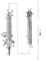
- A catheter system according to the present invention is illustrated in Figure 1. The catheter system comprises a flexible tubular member 3, an ultrasonic transducer 5 and drive means 7. Tubular member 3 has a
proximal end 9, a distal end 11 and acentral lumen 13 connecting the two. Drive means 7 comprises adrive cable 15 rotatably disposed withincentral lumen 13 and amotor coupling 17 at the proximal end of the drive cable. - Ultrasonic transducer 5 is disposed within a
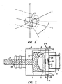
distal housing 14 at distal end 11 of tubular member 3. The transducer is adapted for pivotal movement relative to the tubular member. The distal end ofdrive cable 15 is connected to the ultrasonic transducer by acoupling mechanism 19, which is adapted to convert rotation of the drive cable into pivotal oscillation of the ultrasonic transducer. Transducer 5 is shielded by acover 6. The cover protects the transducer from interference by tissue within the patient and the patient from internal injury from contact with the rapidly oscillating transducer.Cover 6 is made of a acoustically transparent material to allow the transmission of the acoustic waves sent and received by transducer 5. - The pivotal motion of the ultrasonic transducer may be conveniently understood with reference to Fig. 2, which depicts the distal end 11 of tubular member 3, within which transducer 5 is mounted. Transducer 5 pivots within the tubular member about an axis Z and sweeps back and forth through an angle lying within a plane X-Y.
-
Distal housing 14 andcoupling mechanism 19 are shown in greater detail in Fig. 3. The distal housing holds the coupling mechanism. The coupling mechanism comprises three main parts: atransducer holder 20, which has areceptacle 21 in which the transducer is held; anactuator 22 for driving the transducer holder; and astator 23, about which the transducer holder pivots. - Figure 4 is a three view orthogonal projection of
distal housing 14. As can be seen therein, the distal housing has mountingholes coaxial opening 26. -
Actuator 22 is depicted in a two view orthogonal projection in Fig. 5. The actuator has ashaft 28 and anactuator pin 31 set intoconcave surface 33. The actuator pin is set at an angle to the center line of the actuator and the shaft. In a preferred embodiment of the invention, angle is about 45 degrees but the angle may vary. - Figure 6 is a two view projection of
transducer holder 20 andstator 23 disposed therethrough. As mentioned previously, the transducer holder has areceptacle 21 for holding the transducer. The transducer holder also has aslot 36 cut into arounded back surface 38.Slot 36 is adapted for cooperation withactuator pin 31 ofactuator 22 and this will be described in more detail below. - Referring back to Fig. 3, the integration of the parts depicted in Figs. 4 - 6 into the catheter system will now be described.
Shaft 28 ofactuator 22 is rotatably disposed throughcoaxial opening 26 ofdistal housing 14. The coaxial opening acts as a bearing to support the rotating shaft. - The ends of
stator 23 are fixed (e.g., by a press fit) within mountingholes Transducer holder 20 is pivotally disposed about the stator. A pair of coils or windings disposed around the stator act as aninductive coupling 45 for electrical coupling of transducer 5 to an associated control means. The construction and function ofinductive coupling 45 is discussed in detail below. -
Actuator pin 31 is disposed for cooperation withslot 36. The width ofslot 36 is slightly greater than the diameter ofactuator pin 31 so that the pin may slide and rotate within the slot. The pin and slot are thus configured to convert rotation ofactuator 22 into pivotal oscillation oftransducer holder 20 aboutstator 23. -
System control circuitry 50 suitable for controlling the transducer is illustrated schematically in Fig. 7. The control circuitry, which can be formed of substantially conventional equipment, includes a timing and control means 54, atransmitter 57 and areceiver 58 with a transmit/receiveswitch 59, and adisplay unit 60, typically including a CRT tube for displaying an image from within the blood vessel. - In operation, timing and control means 54 sends pulses to
transmitter 57.Transmitter 57 generates voltage for excitation of the transducer 5. The transducer generates ultrasonic energy waves which emanate forwardly into the blood vessel. Portions of the ultrasonic energy waves reflect from tissues within the vessel and are reflected back to the transducer. The transducer receives these reflected waves and converts them into electrical signals which are sent back toreceiver 58 through conductingwires display unit 60, which converts the signals into a visual display of the structure of the vessel. - The transducer is switched between its send and receive modes by transmit/receive
switch 59. Timing and control means 54 controls drivemotor 67, which may be an open loop stepping motor or a closed loop servomotor.Motor 67 rotates drivecable 15, which, as discussed above, causes the transducer to scan back and forth through an arc within the blood vessel. - The scanned arc ( in Fig. 2) will be 90 degrees in the embodiment depicted where
actuator pin 31 is set at a 45 degree angle ( in Fig. 5) to the axis ofactuator shaft 28. Drivecable 15 is preferably rotated at a constant angular velocity. Eighteen hundred (1800) rpm is suitable rotation speed for the embodiment depicted. This translates to a transducer scan rate of 30 oscillations per second, a rate sufficient to provide good image detail with an acceptable image refresh rate. The transducer firing rate is coordinated with its pivotal movement bysystem controller 50. It will be understood that the actual transducer oscillation rate could be varied significantly. - Electrical signals are carried between the system controller and the transducer through conducting
wires - Direct connection of
wires - For these reasons, it is advantageous to eliminate the problem of flexing within
wires inductive coupling 45 adapted to this purpose is shown in place in Fig. 3. - The details and construction of
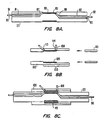
inductive coupling 45 are depicted in Figs. 8A - 8C. Figure 8A depicts a stator assembly in detail. As can be seen therein, awire channel 80, comprisingchannel segments stator 23 from each end. A windinggroove 85 is cut into the surface near the middle of the stator and stator holes 87 and 88 are drilled into the stator to connect windinggroove 85 to channelsegments -
Controller wire 90 is then fed through one channel segment, turned a number of times around the stator at windinggroove 85, and fed out of the other channel segment. The turns ofwire 90 within windinggroove 85 form a stator winding 93 aroundstator 23. The number of turns in winding 93 may obviously vary but in one preferred embodiment there are thirteen turns. - A rotator assembly is depicted in detail in Fig. 8B. A
rotator 100 has an inside diameter slightly larger than the outside diameter ofstator 23 so that the rotator may be disposed to turn about the stator. Along aportion 103 of its length,rotator 100 has an even larger inside diameter to accommodate a winding 105 oftransducer wire 108 and a retainingsleeve 110. - Rotator holes 113 and 114 are bored through the wall of
rotator 100.Transducer wire 108 is fed through one of the holes, wound a number of times about the inside of the rotator to form a rotator winding 105, and finally fed back out through the second of the holes. Retainingsleeve 110 is then fitted withinrotator 100 to hold rotator winding 105 in place. Rotator winding 105 will typically have the same number of turns as stator winding 93; in a preferred embodiment, thirteen. - As depicted in Fig. 8C, the rotator assembly is rotatably disposed about the stator assembly so that the windings are aligned with each other to form
inductive coupling 45. An electrical current flowing withincontroller wire 90 will pass through stator winding 93 disposed within rotator winding 105. This will induce a corresponding electrical current within rotator winding 105 which will flow throughtransducer wire 108. The reverse will also be true--a current flowing through the transducer wire will induce a current within the controller wire. -
Inductive coupling 45 is incorporated into the system as depicted in Figs. 1 and 3. The two ends ofstator 23 are press fit into mountingholes distal housing 14. The rotator is fixed withintransducer holder 20, which pivots about the stator. The two ends 91 and 92 ofcontroller wire 90 are routed back through tubular member 3, and serve as conductingwires Transducer wire 108 is directly connected at each end to transducer 5. - Referring to Fig. 1, tubular member 3 of the catheter system has a three
arm adaptor 120 at its proximal end. Afirst arm 122 of three arm adaptor 3 has conductingwires - A
second arm 123 of the three arm adaptor has afill port 124 and afill channel 125 in communication withcentral lumen 13 of the tubular member. Before imaging, a fluid suitable for the transmission of ultrasonic signals will be injected intofill port 124. The fluid will fill the tubular member of the catheter system and flush air bubbles (which could interfere with imaging) out of the region of the transducer, alongcentral lumen 13, and through adrain channel 127 and adrain port 128 of athird arm 129 of the three arm adaptor. - Electrical impulses will then be sent from the controller along conducting
wires - The ultrasonic waves will be reflected from structures within the blood vessels and returned to the transducer. The transducer will receive the reflected waves and convert them into electrical signals. The electrical. signals will travel back through the inductive coupling and into conducting
wires - Referring back to Fig. 2, it will be appreciated that by rotating the transducer about axis X as it pivots back and forth within plane X-Y, the transducer may be caused to scan a series of planes within the blood vessel and thereby to image a three-dimensional region of the blood vessel. In the simplest case, this may be done by simply rotating the entire catheter body within the patient's blood vessel. This will cause pivot axis Z of transducer 5 to rotate about axis X. The surgeon operating the system can simply form a mental image of a three dimensional region of the vessel as he rotates the catheter body through a series of imaging planes.
- With further development, mechanical means for rotating pivot axis Z of the transducer about axis X could be devised. This mechanical rotation means could even be synchronized with the equipment for displaying the image, so that real time three dimensional images could be displayed directly by the imaging equipment.
- A forward viewing imaging catheter system according to the present invention may be combined advantageously with other diagnostic or interventional work elements. Figure. 9 depicts a forward viewing imaging catheter in combination with a
biopsy tool 130 for sampling adeposit 140 within the blood vessel. Thedeposit 140 depicted lies within the imaging plane of the catheter system. Abiopsy tool 130 comprising atool tip 134 and atool shaft 135 is disposed within anadditional tool lumen 136. The system depicted in Fig. 9 may greatly assist a physician in performing the biopsy procedure. The physician may conveniently view the deposit and the biopsy tip while the sample is being taken. - Other combinations are possible. For example, a rotating cutter, a balloon angioplasty device, a laser ablation device or some other device for treating a stenosis with the blood vessel could conveniently be carried by
additional lumen 136. In such a system, the forward viewing capability would allow for simultaneous imaging and treatment of the region of interest within the vessel.
Claims (14)
- A forward viewing imaging catheter system for imaging a blood vessel within a patient, comprising:characterized in thata flexible tubular member (3) adapted for insertion into the blood vessel, the tubular member (3) having proximal and distal ends (9, 11) and a longitudinal axis (X);an ultrasonic transducer (5) located near the distal end of the tubular member (3) and disposed to send and receive signals in a direction forward of the distal end (11); andmeans for moving the transducer (5) about an axis to scan an area forward of the catheter, said means including a flexible drive means (15) disposed within the flexible tubular member (3) for rotational movement therein;
said means for moving the transducer (5) comprises a mechanism (19) coupled to the flexible drive means (15) and for converting rotation of the flexible drive means (15) into pivotal oscillation of the transducer (5) in a plane (X-Y) about an axis (Z) perpendicular to the longitudinal axis (X),
said mechanism (19) comprising a stator (23) about which the transducer (5) is pivotably disposed,
said stator (23) and the transducer (5) being provided with an inductive coupling (45) for electrical coupling of the transducer (5) for transmitting electrical signals to and from the transducer. - The catheter system of claim 1, wherein the stator (23) is disposed in a distal housing (14) for the mechanism (19), said distal housing (14) being disposed near the distal end of the tubular member (3).
- The catheter system of claim 2, wherein a transducer holder (20) for the transducer (5) is provided in the distal housing (14) and coupled to the mechanism (19).
- The catheter system of claim 3, wherein the mechanism (19) comprises an actuator (22) having a pin (31) carried at an angle to the axis of rotation of the drive means (15), the transducer holder (20) is provided with a slot (34) and the pin (31) is engaged with the slot (36).
- The catheter system of claim 4, wherein the angle between the pin (31) and the axis of rotation is between 30° and 60°, especially substantially equal to 45°.
- The catheter system of to anyone of the claims 1 to 5, wherein a pair of wires (62, 64) is disposed within the tubular member (3) for transmitting electrical signals to and from the transducer (5) via the inductive coupling (45).
- The catheter system of anyone of the claims 1 to 6, wherein the inductive coupling (45) comprises stator and transducer windings (93, 105) which are disposed concentrically to each other.
- The catheter system of claim 7, wherein the transducer and stator windings (105, 93) each comprise between 5 and 25 coils.
- The catheter system of claim 7 or 8, wherein the stator winding (93) lies within a winding groove (85) disposed within a surface of the stator (23).
- The catheter system of anyone of the claims 7 to 9 if dependent on claim 3, wherein the transducer winding (105) is disposed within the transducer holder (20).
- The catheter system of anyone of the claims 1 to 10, wherein a fill port (124) and a drain port (128) are provided at the proximal end of the tubular member (3) and a motor coupling connected to the flexible drive means (15) is provided for connecting a motor (67) to the drive means (15).
- The catheter system of anyone of the claims 1 to 11, wherein means for creating a visual display of a portion of the vessel being scanned by the transducer (5) is provided.
- The catheter system of claim 12, wherein the display means (60) includes a cathode ray tube.
- The catheter system of anyone of the claims 1 to 13, wherein a work element, especially a biopsy tool (132) for sampling a deposit within the blood vessel, is provided.
Applications Claiming Priority (3)
| Application Number | Priority Date | Filing Date | Title |
|---|---|---|---|
| US08/006,224 US5373849A (en) | 1993-01-19 | 1993-01-19 | Forward viewing imaging catheter |
| US6224 | 1993-01-19 | ||
| PCT/US1994/000464 WO1994016625A1 (en) | 1993-01-19 | 1994-01-14 | Forward viewing imaging catheter |
Publications (3)
| Publication Number | Publication Date |
|---|---|
| EP0681454A1 EP0681454A1 (en) | 1995-11-15 |
| EP0681454A4 EP0681454A4 (en) | 1996-03-13 |
| EP0681454B1 true EP0681454B1 (en) | 2003-04-23 |
Family
ID=21719870
Family Applications (1)
| Application Number | Title | Priority Date | Filing Date |
|---|---|---|---|
| EP94908591A Expired - Lifetime EP0681454B1 (en) | 1993-01-19 | 1994-01-14 | Forward viewing imaging catheter system |
Country Status (8)
| Country | Link |
|---|---|
| US (1) | US5373849A (en) |
| EP (1) | EP0681454B1 (en) |
| JP (1) | JPH08510654A (en) |
| AT (1) | ATE237996T1 (en) |
| CA (1) | CA2154162A1 (en) |
| DE (1) | DE69432557T2 (en) |
| ES (1) | ES2197906T3 (en) |
| WO (1) | WO1994016625A1 (en) |
Cited By (1)
| Publication number | Priority date | Publication date | Assignee | Title |
|---|---|---|---|---|
| CN107427285A (en) * | 2015-04-13 | 2017-12-01 | 内尔松·若热·特谢拉·多斯·桑托斯·保罗 | The device for intracardiac and intravascular surgical operation with endo-luminal ultrasound probe |
Families Citing this family (176)
| Publication number | Priority date | Publication date | Assignee | Title |
|---|---|---|---|---|
| US6029671A (en) * | 1991-07-16 | 2000-02-29 | Heartport, Inc. | System and methods for performing endovascular procedures |
| US5704361A (en) * | 1991-11-08 | 1998-01-06 | Mayo Foundation For Medical Education And Research | Volumetric image ultrasound transducer underfluid catheter system |
| US5325860A (en) | 1991-11-08 | 1994-07-05 | Mayo Foundation For Medical Education And Research | Ultrasonic and interventional catheter and method |
| US6285898B1 (en) | 1993-07-20 | 2001-09-04 | Biosense, Inc. | Cardiac electromechanics |
| US5738096A (en) * | 1993-07-20 | 1998-04-14 | Biosense, Inc. | Cardiac electromechanics |
| US6983179B2 (en) | 1993-07-20 | 2006-01-03 | Biosense, Inc. | Method for mapping a heart using catheters having ultrasonic position sensors |
| US5606975A (en) * | 1994-09-19 | 1997-03-04 | The Board Of Trustees Of The Leland Stanford Junior University | Forward viewing ultrasonic imaging catheter |
| US6027450A (en) * | 1994-12-30 | 2000-02-22 | Devices For Vascular Intervention | Treating a totally or near totally occluded lumen |
| WO1997010748A1 (en) | 1995-09-20 | 1997-03-27 | Texas Heart Institute | Detecting thermal discrepancies in vessel walls |
| US6763261B2 (en) | 1995-09-20 | 2004-07-13 | Board Of Regents, The University Of Texas System | Method and apparatus for detecting vulnerable atherosclerotic plaque |
| US6615071B1 (en) | 1995-09-20 | 2003-09-02 | Board Of Regents, The University Of Texas System | Method and apparatus for detecting vulnerable atherosclerotic plaque |
| US6302875B1 (en) * | 1996-10-11 | 2001-10-16 | Transvascular, Inc. | Catheters and related devices for forming passageways between blood vessels or other anatomical structures |
| US6190353B1 (en) * | 1995-10-13 | 2001-02-20 | Transvascular, Inc. | Methods and apparatus for bypassing arterial obstructions and/or performing other transvascular procedures |
| US6283951B1 (en) | 1996-10-11 | 2001-09-04 | Transvascular, Inc. | Systems and methods for delivering drugs to selected locations within the body |
| US6375615B1 (en) | 1995-10-13 | 2002-04-23 | Transvascular, Inc. | Tissue penetrating catheters having integral imaging transducers and their methods of use |
| CA2234389A1 (en) * | 1995-10-13 | 1997-04-17 | Transvascular, Inc. | A device, system and method for interstitial transvascular intervention |
| US6915149B2 (en) | 1996-01-08 | 2005-07-05 | Biosense, Inc. | Method of pacing a heart using implantable device |
| DE69726576T2 (en) | 1996-02-15 | 2004-10-14 | Biosense, Inc., Miami | Placemark sample |
| US6321109B2 (en) | 1996-02-15 | 2001-11-20 | Biosense, Inc. | Catheter based surgery |
| DE69733604T2 (en) | 1996-02-15 | 2006-05-11 | Biosense Webster, Inc., Diamond Bar | MOVABLE RECEIVING AND TRANSMISSION PANS FOR A LOCAL DETERMINATION SYSTEM |
| US6253770B1 (en) | 1996-02-15 | 2001-07-03 | Biosense, Inc. | Catheter with lumen |
| IL125781A (en) | 1996-02-15 | 2003-06-24 | Biosense Inc | Precise position determination of endoscopes |
| CA2246340C (en) | 1996-02-15 | 2005-08-16 | Biosense, Inc. | Catheter calibration and usage monitoring system |
| ES2210498T3 (en) | 1996-02-15 | 2004-07-01 | Biosense, Inc. | POSITIONABLE TRANSDUCERS INDEPENDENTLY FOR LOCATION SYSTEM. |
| DE69733341T2 (en) | 1996-02-27 | 2006-02-02 | Biosense Webster, Inc., Diamond Bar | LOCATION PROCESS WITH FIELD ASSESSMENT SEQUENCES |
| IL127017A (en) * | 1996-05-17 | 2003-07-06 | Biosense Inc | Self-aligning catheter |
| US5699805A (en) * | 1996-06-20 | 1997-12-23 | Mayo Foundation For Medical Education And Research | Longitudinal multiplane ultrasound transducer underfluid catheter system |
| JPH1028687A (en) * | 1996-07-18 | 1998-02-03 | Ge Yokogawa Medical Syst Ltd | Ultrasonic imaging method and device |
| US6245026B1 (en) | 1996-07-29 | 2001-06-12 | Farallon Medsystems, Inc. | Thermography catheter |
| US20020077564A1 (en) * | 1996-07-29 | 2002-06-20 | Farallon Medsystems, Inc. | Thermography catheter |
| US5924997A (en) * | 1996-07-29 | 1999-07-20 | Campbell; Thomas Henderson | Catheter and method for the thermal mapping of hot spots in vascular lesions of the human body |
| US5906636A (en) | 1996-09-20 | 1999-05-25 | Texas Heart Institute | Heat treatment of inflamed tissue |
| US7603166B2 (en) | 1996-09-20 | 2009-10-13 | Board Of Regents University Of Texas System | Method and apparatus for detection of vulnerable atherosclerotic plaque |
| US5830145A (en) | 1996-09-20 | 1998-11-03 | Cardiovascular Imaging Systems, Inc. | Enhanced accuracy of three-dimensional intraluminal ultrasound (ILUS) image reconstruction |
| US5827313A (en) * | 1996-09-27 | 1998-10-27 | Boston Scientific Corporation | Device for controlled longitudinal movement of an operative element within a catheter sheath and method |
| US5957941A (en) * | 1996-09-27 | 1999-09-28 | Boston Scientific Corporation | Catheter system and drive assembly thereof |
| US5853368A (en) * | 1996-12-23 | 1998-12-29 | Hewlett-Packard Company | Ultrasound imaging catheter having an independently-controllable treatment structure |
| US6171247B1 (en) | 1997-06-13 | 2001-01-09 | Mayo Foundation For Medical Education And Research | Underfluid catheter system and method having a rotatable multiplane transducer |
| US6078831A (en) | 1997-09-29 | 2000-06-20 | Scimed Life Systems, Inc. | Intravascular imaging guidewire |
| JP4373605B2 (en) * | 1998-01-26 | 2009-11-25 | ボストン サイエンティフィック リミテッド | Catheter assembly with remote inductive coupler and embedded transmission path |
| US6200269B1 (en) * | 1998-05-28 | 2001-03-13 | Diasonics, Ultrasound, Inc. | Forward-scanning ultrasound catheter probe |
| US6059731A (en) * | 1998-08-19 | 2000-05-09 | Mayo Foundation For Medical Education And Research | Simultaneous side-and-end viewing underfluid catheter |
| US6626852B2 (en) | 1998-09-08 | 2003-09-30 | Scimed Life Systems, Inc. | System for intraluminal imaging |
| US6419644B1 (en) | 1998-09-08 | 2002-07-16 | Scimed Life Systems, Inc. | System and method for intraluminal imaging |
| US6793634B2 (en) | 1998-10-23 | 2004-09-21 | Scimed Life Systems, Inc. | System and method for intraluminal imaging |
| AU1940200A (en) * | 1998-12-16 | 2000-07-03 | Fox Hollow Technologies, Inc. | Guidewire having sidewise looking imaging capabilities and method |
| US6398736B1 (en) | 1999-03-31 | 2002-06-04 | Mayo Foundation For Medical Education And Research | Parametric imaging ultrasound catheter |
| US7426409B2 (en) | 1999-06-25 | 2008-09-16 | Board Of Regents, The University Of Texas System | Method and apparatus for detecting vulnerable atherosclerotic plaque |
| US6315732B1 (en) * | 1999-07-20 | 2001-11-13 | Scimed Life Systems, Inc. | Imaging catheter and methods of use for ultrasound-guided ablation |
| US7708749B2 (en) | 2000-12-20 | 2010-05-04 | Fox Hollow Technologies, Inc. | Debulking catheters and methods |
| US6299622B1 (en) | 1999-08-19 | 2001-10-09 | Fox Hollow Technologies, Inc. | Atherectomy catheter with aligned imager |
| US7713279B2 (en) | 2000-12-20 | 2010-05-11 | Fox Hollow Technologies, Inc. | Method and devices for cutting tissue |
| US8328829B2 (en) | 1999-08-19 | 2012-12-11 | Covidien Lp | High capacity debulking catheter with razor edge cutting window |
| JP4662515B2 (en) * | 2000-09-22 | 2011-03-30 | セイコーインスツル株式会社 | Medical module equipment |
| WO2002049690A2 (en) | 2000-12-20 | 2002-06-27 | Fox Hollow Technologies, Inc. | Debulking catheter |
| US6694181B2 (en) | 2001-02-12 | 2004-02-17 | Scimed Life Systems, Inc. | Methods and devices for detecting vulnerable plaque |
| US6514214B2 (en) | 2001-02-13 | 2003-02-04 | Scimed Life Systems, Inc. | Intravascular temperature sensor |
| WO2003094715A1 (en) * | 2002-05-07 | 2003-11-20 | Volcano Therapeutics, Inc. | Systems and methods for detecting vulnerable plaque |
| EP1551306A4 (en) * | 2002-09-18 | 2008-03-05 | Univ Leland Stanford Junior | Tubular compliant mechanisms for ultrasonic imaging systems and intravascular interventional devices |
| US20070167804A1 (en) * | 2002-09-18 | 2007-07-19 | Byong-Ho Park | Tubular compliant mechanisms for ultrasonic imaging systems and intravascular interventional devices |
| US7715896B2 (en) | 2003-03-21 | 2010-05-11 | Boston Scientific Scimed, Inc. | Systems and methods for internal tissue penetration |
| US8246640B2 (en) | 2003-04-22 | 2012-08-21 | Tyco Healthcare Group Lp | Methods and devices for cutting tissue at a vascular location |
| JP4792467B2 (en) * | 2004-10-14 | 2011-10-12 | コーニンクレッカ フィリップス エレクトロニクス エヌ ヴィ | Ablation apparatus and method with ultrasound imaging |
| US7967754B2 (en) * | 2004-10-14 | 2011-06-28 | Scimed Life Systems, Inc. | Integrated bias circuitry for ultrasound imaging devices configured to image the interior of a living being |
| US20060111704A1 (en) * | 2004-11-22 | 2006-05-25 | Rox Medical, Inc. | Devices, systems, and methods for energy assisted arterio-venous fistula creation |
| US8491484B2 (en) * | 2005-04-12 | 2013-07-23 | Scimed Life Systems, Inc. | Forward looking imaging guidewire |
| US20070016062A1 (en) * | 2005-05-04 | 2007-01-18 | Byong-Ho Park | Multiple transducers for intravascular ultrasound imaging |
| US7544166B2 (en) * | 2005-06-03 | 2009-06-09 | Scimed Life Systems, Inc. | Systems and methods for imaging with deployable imaging devices |
| US8303510B2 (en) * | 2005-07-01 | 2012-11-06 | Scimed Life Systems, Inc. | Medical imaging device having a forward looking flow detector |
| US8047996B2 (en) * | 2005-10-31 | 2011-11-01 | Volcano Corporation | System and method for reducing angular geometric distortion in an imaging device |
| US7785286B2 (en) * | 2006-03-30 | 2010-08-31 | Volcano Corporation | Method and system for imaging, diagnosing, and/or treating an area of interest in a patient's body |
| US7612773B2 (en) * | 2006-05-22 | 2009-11-03 | Magnin Paul A | Apparatus and method for rendering for display forward-looking image data |
| US20070276419A1 (en) | 2006-05-26 | 2007-11-29 | Fox Hollow Technologies, Inc. | Methods and devices for rotating an active element and an energy emitter on a catheter |
| JP2010500153A (en) * | 2006-08-14 | 2010-01-07 | ノベリス・インコーポレーテッド | Imaging apparatus, imaging system, and imaging method |
| US9867530B2 (en) | 2006-08-14 | 2018-01-16 | Volcano Corporation | Telescopic side port catheter device with imaging system and method for accessing side branch occlusions |
| KR100949067B1 (en) * | 2006-12-27 | 2010-03-25 | 주식회사 메디슨 | Device for pivoting ultrasound element of probe in ultra sonic diagnosis apparatus |
| US8460195B2 (en) * | 2007-01-19 | 2013-06-11 | Sunnybrook Health Sciences Centre | Scanning mechanisms for imaging probe |
| CN101662980B (en) | 2007-01-19 | 2013-02-27 | 桑尼布鲁克健康科学中心 | Scanning mechanisms for imaging probe |
| JP2008237235A (en) * | 2007-03-23 | 2008-10-09 | Olympus Medical Systems Corp | Endoscope and biological observation system |
| US8172757B2 (en) * | 2007-06-18 | 2012-05-08 | Sunnybrook Health Sciences Centre | Methods and devices for image-guided manipulation or sensing or anatomic structures |
| US9596993B2 (en) | 2007-07-12 | 2017-03-21 | Volcano Corporation | Automatic calibration systems and methods of use |
| WO2009009799A1 (en) | 2007-07-12 | 2009-01-15 | Volcano Corporation | Catheter for in vivo imaging |
| US10219780B2 (en) | 2007-07-12 | 2019-03-05 | Volcano Corporation | OCT-IVUS catheter for concurrent luminal imaging |
| US8784440B2 (en) | 2008-02-25 | 2014-07-22 | Covidien Lp | Methods and devices for cutting tissue |
| KR101645754B1 (en) | 2008-10-13 | 2016-08-04 | 코비디엔 엘피 | Devices and methods for manipulating a catheter shaft |
| US8317713B2 (en) * | 2009-01-09 | 2012-11-27 | Volcano Corporation | Ultrasound catheter with rotatable transducer |
| JP2012519563A (en) * | 2009-03-09 | 2012-08-30 | コーニンクレッカ フィリップス エレクトロニクス エヌ ヴィ | Catheter, device, method and computer program for applying energy to a subject |
| US20100249604A1 (en) * | 2009-03-31 | 2010-09-30 | Boston Scientific Corporation | Systems and methods for making and using a motor distally-positioned within a catheter of an intravascular ultrasound imaging system |
| US8647281B2 (en) * | 2009-03-31 | 2014-02-11 | Boston Scientific Scimed, Inc. | Systems and methods for making and using an imaging core of an intravascular ultrasound imaging system |
| US8298149B2 (en) * | 2009-03-31 | 2012-10-30 | Boston Scientific Scimed, Inc. | Systems and methods for making and using a motor distally-positioned within a catheter of an intravascular ultrasound imaging system |
| US9687266B2 (en) | 2009-04-29 | 2017-06-27 | Covidien Lp | Methods and devices for cutting and abrading tissue |
| CA2761774C (en) | 2009-05-14 | 2014-09-16 | Tyco Healthcare Group Lp | Easily cleaned atherectomy catheters and methods of use |
| US20110028848A1 (en) | 2009-07-31 | 2011-02-03 | Cem Shaquer | Methods and Apparatus for Detecting and Mapping Tissue Interfaces |
| US20110071400A1 (en) * | 2009-09-23 | 2011-03-24 | Boston Scientific Scimed, Inc. | Systems and methods for making and using intravascular ultrasound imaging systems with sealed imaging cores |
| US20110071401A1 (en) * | 2009-09-24 | 2011-03-24 | Boston Scientific Scimed, Inc. | Systems and methods for making and using a stepper motor for an intravascular ultrasound imaging system |
| EP2913013B1 (en) | 2009-12-02 | 2016-11-09 | Covidien LP | Methods and devices for cutting tissue |
| RU2520801C2 (en) | 2009-12-11 | 2014-06-27 | ТАЙКО ХЕЛСКЕА ГРУП эЛПи | Device for material removal with improved capture efficiency and methods for using |
| RU2538174C2 (en) | 2010-06-14 | 2015-01-10 | Ковидиен Лп | Device for material removal |
| KR101518147B1 (en) | 2010-10-28 | 2015-05-06 | 코비디엔 엘피 | Material removal device and method of use |
| EP2637567B1 (en) | 2010-11-11 | 2017-03-08 | Covidien LP | Flexible debulking catheters with imaging and methods of manufacture |
| US11141063B2 (en) | 2010-12-23 | 2021-10-12 | Philips Image Guided Therapy Corporation | Integrated system architectures and methods of use |
| US11040140B2 (en) | 2010-12-31 | 2021-06-22 | Philips Image Guided Therapy Corporation | Deep vein thrombosis therapeutic methods |
| WO2013033489A1 (en) | 2011-08-31 | 2013-03-07 | Volcano Corporation | Optical rotary joint and methods of use |
| JP5806407B2 (en) | 2011-09-01 | 2015-11-10 | コヴィディエン リミテッド パートナーシップ | Catheter with helical drive shaft and manufacturing method |
| WO2013035374A1 (en) | 2011-09-09 | 2013-03-14 | オリンパスメディカルシステムズ株式会社 | Ultrasonic endoscope |
| WO2013055917A1 (en) | 2011-10-12 | 2013-04-18 | Volcano Corporation | Rotational shape-memory actuators and associated devices, systems, and methods |
| US9164084B2 (en) | 2012-01-31 | 2015-10-20 | Purdue Research Foundation | Methods for determining aggressiveness of a cancer and treatment thereof |
| US9579157B2 (en) | 2012-09-13 | 2017-02-28 | Covidien Lp | Cleaning device for medical instrument and method of use |
| US9324141B2 (en) | 2012-10-05 | 2016-04-26 | Volcano Corporation | Removal of A-scan streaking artifact |
| US9292918B2 (en) | 2012-10-05 | 2016-03-22 | Volcano Corporation | Methods and systems for transforming luminal images |
| US9367965B2 (en) | 2012-10-05 | 2016-06-14 | Volcano Corporation | Systems and methods for generating images of tissue |
| US10568586B2 (en) | 2012-10-05 | 2020-02-25 | Volcano Corporation | Systems for indicating parameters in an imaging data set and methods of use |
| US9307926B2 (en) | 2012-10-05 | 2016-04-12 | Volcano Corporation | Automatic stent detection |
| US10070827B2 (en) | 2012-10-05 | 2018-09-11 | Volcano Corporation | Automatic image playback |
| JP2015532536A (en) | 2012-10-05 | 2015-11-09 | デイビッド ウェルフォード, | System and method for amplifying light |
| US9858668B2 (en) | 2012-10-05 | 2018-01-02 | Volcano Corporation | Guidewire artifact removal in images |
| US9286673B2 (en) | 2012-10-05 | 2016-03-15 | Volcano Corporation | Systems for correcting distortions in a medical image and methods of use thereof |
| US11272845B2 (en) | 2012-10-05 | 2022-03-15 | Philips Image Guided Therapy Corporation | System and method for instant and automatic border detection |
| US9840734B2 (en) | 2012-10-22 | 2017-12-12 | Raindance Technologies, Inc. | Methods for analyzing DNA |
| US9943329B2 (en) | 2012-11-08 | 2018-04-17 | Covidien Lp | Tissue-removing catheter with rotatable cutter |
| EP2931132B1 (en) | 2012-12-13 | 2023-07-05 | Philips Image Guided Therapy Corporation | System for targeted cannulation |
| US10942022B2 (en) | 2012-12-20 | 2021-03-09 | Philips Image Guided Therapy Corporation | Manual calibration of imaging system |
| CA2895989A1 (en) | 2012-12-20 | 2014-07-10 | Nathaniel J. Kemp | Optical coherence tomography system that is reconfigurable between different imaging modes |
| US10939826B2 (en) | 2012-12-20 | 2021-03-09 | Philips Image Guided Therapy Corporation | Aspirating and removing biological material |
| EP2934311B1 (en) | 2012-12-20 | 2020-04-15 | Volcano Corporation | Smooth transition catheters |
| US20140180118A1 (en) * | 2012-12-20 | 2014-06-26 | Volcano Corporation | Catheter Assembly with a Shortened Tip |
| EP2934282B1 (en) | 2012-12-20 | 2020-04-29 | Volcano Corporation | Locating intravascular images |
| US11406498B2 (en) | 2012-12-20 | 2022-08-09 | Philips Image Guided Therapy Corporation | Implant delivery system and implants |
| US10058284B2 (en) | 2012-12-21 | 2018-08-28 | Volcano Corporation | Simultaneous imaging, monitoring, and therapy |
| WO2014099763A1 (en) | 2012-12-21 | 2014-06-26 | Jason Spencer | System and method for graphical processing of medical data |
| CA2895990A1 (en) | 2012-12-21 | 2014-06-26 | Jerome MAI | Ultrasound imaging with variable line density |
| US9383263B2 (en) | 2012-12-21 | 2016-07-05 | Volcano Corporation | Systems and methods for narrowing a wavelength emission of light |
| US10413317B2 (en) | 2012-12-21 | 2019-09-17 | Volcano Corporation | System and method for catheter steering and operation |
| WO2014100397A1 (en) * | 2012-12-21 | 2014-06-26 | Jason Spencer | Catheter orienting markers |
| EP2934307B1 (en) | 2012-12-21 | 2020-08-05 | Volcano Corporation | Functional gain measurement technique and representation |
| EP2934653B1 (en) | 2012-12-21 | 2018-09-19 | Douglas Meyer | Rotational ultrasound imaging catheter with extended catheter body telescope |
| WO2014100162A1 (en) | 2012-12-21 | 2014-06-26 | Kemp Nathaniel J | Power-efficient optical buffering using optical switch |
| JP2016501623A (en) | 2012-12-21 | 2016-01-21 | アンドリュー ハンコック, | System and method for multipath processing of image signals |
| US9486143B2 (en) | 2012-12-21 | 2016-11-08 | Volcano Corporation | Intravascular forward imaging device |
| CA2895759A1 (en) * | 2012-12-21 | 2014-06-26 | Joseph Fallon | Rotational imaging apparatus |
| US9612105B2 (en) | 2012-12-21 | 2017-04-04 | Volcano Corporation | Polarization sensitive optical coherence tomography system |
| US9770172B2 (en) | 2013-03-07 | 2017-09-26 | Volcano Corporation | Multimodal segmentation in intravascular images |
| US10226597B2 (en) | 2013-03-07 | 2019-03-12 | Volcano Corporation | Guidewire with centering mechanism |
| EP2967391A4 (en) | 2013-03-12 | 2016-11-02 | Donna Collins | Systems and methods for diagnosing coronary microvascular disease |
| US20140276923A1 (en) | 2013-03-12 | 2014-09-18 | Volcano Corporation | Vibrating catheter and methods of use |
| JP6339170B2 (en) | 2013-03-13 | 2018-06-06 | ジンヒョン パーク | System and method for generating images from a rotating intravascular ultrasound device |
| US11026591B2 (en) | 2013-03-13 | 2021-06-08 | Philips Image Guided Therapy Corporation | Intravascular pressure sensor calibration |
| US9301687B2 (en) | 2013-03-13 | 2016-04-05 | Volcano Corporation | System and method for OCT depth calibration |
| US10426590B2 (en) | 2013-03-14 | 2019-10-01 | Volcano Corporation | Filters with echogenic characteristics |
| US10292677B2 (en) | 2013-03-14 | 2019-05-21 | Volcano Corporation | Endoluminal filter having enhanced echogenic properties |
| US10219887B2 (en) | 2013-03-14 | 2019-03-05 | Volcano Corporation | Filters with echogenic characteristics |
| EP2973424B1 (en) | 2013-03-15 | 2018-02-21 | Conavi Medical Inc. | Data display and processing algorithms for 3d imaging systems |
| US20160022244A1 (en) * | 2013-03-15 | 2016-01-28 | Colibri Technologies Inc. | Medical probes having internal hydrophilic surfaces |
| JP2017502715A (en) | 2013-11-18 | 2017-01-26 | コーニンクレッカ フィリップス エヌ ヴェKoninklijke Philips N.V. | Thrombus dispersion method and apparatus |
| EP3076881B1 (en) | 2013-11-18 | 2022-01-05 | Koninklijke Philips N.V. | Guided thrombus dispersal catheter |
| WO2015095806A2 (en) | 2013-12-20 | 2015-06-25 | Microvention, Inc. | Device delivery system |
| EP3091906A4 (en) | 2014-01-10 | 2017-01-11 | Volcano Corporation | Detecting endoleaks associated with aneurysm repair |
| US10575822B2 (en) | 2014-01-10 | 2020-03-03 | Philips Image Guided Therapy Corporation | Detecting endoleaks associated with aneurysm repair |
| WO2015108957A1 (en) | 2014-01-14 | 2015-07-23 | Volcano Corporation | Systems for improving an av access site |
| US10874409B2 (en) | 2014-01-14 | 2020-12-29 | Philips Image Guided Therapy Corporation | Methods and systems for clearing thrombus from a vascular access site |
| US10238816B2 (en) | 2014-01-14 | 2019-03-26 | Volcano Corporation | Devices and methods for forming vascular access |
| JP6389526B2 (en) | 2014-01-14 | 2018-09-12 | ボルケーノ コーポレイション | System and method for assessing hemodialysis arteriovenous fistula maturation |
| US20150297259A1 (en) | 2014-01-14 | 2015-10-22 | Volcano Corporation | Catheter assembly for vascular access site creation |
| US20150297097A1 (en) | 2014-01-14 | 2015-10-22 | Volcano Corporation | Vascular access evaluation and treatment |
| WO2015156945A1 (en) | 2014-04-11 | 2015-10-15 | Jeremy Stigall | Imaging and treatment device |
| WO2015200702A1 (en) | 2014-06-27 | 2015-12-30 | Covidien Lp | Cleaning device for catheter and catheter including the same |
| EP3169249B1 (en) | 2014-07-15 | 2018-11-28 | Koninklijke Philips N.V. | Devices for intrahepatic shunts |
| WO2016027198A1 (en) | 2014-08-21 | 2016-02-25 | Koninklijke Philips N.V. | Device and methods for crossing occlusions |
| JP6772161B2 (en) | 2015-02-20 | 2020-10-21 | コーニンクレッカ フィリップス エヌ ヴェKoninklijke Philips N.V. | Atherosclerosis device with imaging |
| US10314667B2 (en) | 2015-03-25 | 2019-06-11 | Covidien Lp | Cleaning device for cleaning medical instrument |
| WO2016170446A1 (en) | 2015-04-20 | 2016-10-27 | Koninklijke Philips N.V. | Dual lumen diagnostic catheter |
| US10292721B2 (en) | 2015-07-20 | 2019-05-21 | Covidien Lp | Tissue-removing catheter including movable distal tip |
| US10314664B2 (en) | 2015-10-07 | 2019-06-11 | Covidien Lp | Tissue-removing catheter and tissue-removing element with depth stop |
| EP3813674A1 (en) | 2018-06-28 | 2021-05-05 | Koninklijke Philips N.V. | Internal ultrasound assisted local therapeutic delivery |
| EP3813677A1 (en) | 2018-06-28 | 2021-05-05 | Koninklijke Philips N.V. | External targeted delivery of active therapeutic agents |
| US20220175269A1 (en) | 2020-12-07 | 2022-06-09 | Frond Medical Inc. | Methods and Systems for Body Lumen Medical Device Location |
Citations (1)
| Publication number | Priority date | Publication date | Assignee | Title |
|---|---|---|---|---|
| US5000185A (en) * | 1986-02-28 | 1991-03-19 | Cardiovascular Imaging Systems, Inc. | Method for intravascular two-dimensional ultrasonography and recanalization |
Family Cites Families (28)
| Publication number | Priority date | Publication date | Assignee | Title |
|---|---|---|---|---|
| CH351202A (en) * | 1955-05-10 | 1960-12-31 | Reiners Walter Ing Dr | Method and device for pulling off a textile thread from an overhead lap over a thread guide member while influencing the thread tension |
| US3955561A (en) * | 1974-09-16 | 1976-05-11 | Indianapolis Center For Advanced Research, Inc. | Cardioscan probe |
| JPS52130178A (en) * | 1976-04-23 | 1977-11-01 | Tokyo Shibaura Electric Co | Ultrasonic high speed repetition scanning device |
| US4375818A (en) * | 1979-03-12 | 1983-03-08 | Olympus Optical Company Ltd. | Ultrasonic diagnosis system assembled into endoscope |
| DE3175444D1 (en) * | 1980-07-29 | 1986-11-13 | Jacques Dory | Probe for echography with sectional mechanical scanning |
| US4399703A (en) * | 1980-10-16 | 1983-08-23 | Dymax Corporation | Ultrasonic transducer and integral drive circuit therefor |
| US4424813A (en) * | 1981-08-14 | 1984-01-10 | Diasonics, Inc. | Multi-mode ultrasound scanner |
| US4433691A (en) * | 1981-10-05 | 1984-02-28 | Honeywell Inc. | Moving torque coil oscillatory drive member |
| FR2516246A1 (en) * | 1981-11-06 | 1983-05-13 | Cgr Ultrasonic | ULTRASOUND PROBE WITH SECTORAL MECHANICAL SCANNING |
| US4479388A (en) * | 1982-09-20 | 1984-10-30 | Dymax Corporation | Ultrasound transducer and drive system |
| US4576177A (en) * | 1983-02-18 | 1986-03-18 | Webster Wilton W Jr | Catheter for removing arteriosclerotic plaque |
| EP0129878B1 (en) * | 1983-06-23 | 1989-01-11 | Matsushita Electric Industrial Co., Ltd. | Ultrasonic probe having dual-motion transducer |
| US4515017A (en) * | 1983-11-21 | 1985-05-07 | Advanced Technology Laboratories, Inc. | Oscillating ultrasound scanhead |
| US4785819A (en) * | 1984-03-30 | 1988-11-22 | Technicare Corporation | Ultrasonic in-line sector probe |
| JPS60249944A (en) * | 1984-05-28 | 1985-12-10 | 株式会社日立メディコ | Ultrasonic probe |
| US4587972A (en) * | 1984-07-16 | 1986-05-13 | Morantte Jr Bernardo D | Device for diagnostic and therapeutic intravascular intervention |
| US4841978A (en) * | 1984-12-24 | 1989-06-27 | North American Philips Corporation | Ultrasonic scanning device with elastic pumper |
| US4794931A (en) * | 1986-02-28 | 1989-01-03 | Cardiovascular Imaging Systems, Inc. | Catheter apparatus, system and method for intravascular two-dimensional ultrasonography |
| DE8704185U1 (en) * | 1987-03-20 | 1988-07-21 | Siemens AG, 1000 Berlin und 8000 München | Ultrasonic applicator for sector scanning |
| US4936307A (en) * | 1987-04-20 | 1990-06-26 | Olympus Optical Co., Ltd. | Ultrasonic observation system and an ultrasonic endoscope system |
| US4869263A (en) * | 1988-02-04 | 1989-09-26 | Cardiometrics, Inc. | Device and method for measuring volumetric blood flow in a vessel |
| JPH0255050A (en) * | 1988-08-22 | 1990-02-23 | Toshiba Corp | Mechanical scanning type ultrasonic probe |
| US5049130A (en) * | 1988-12-23 | 1991-09-17 | Cardiovascular Imaging Systems, Inc. | System and method for pressure filling of catheters |
| US5024234A (en) * | 1989-10-17 | 1991-06-18 | Cardiovascular Imaging Systems, Inc. | Ultrasonic imaging catheter with guidewire channel |
| JPH03272752A (en) * | 1990-03-20 | 1991-12-04 | Fujitsu Ltd | Ultrasonic probe |
| US5161537A (en) * | 1990-03-26 | 1992-11-10 | Matsushita Electric Industrial Co., Ltd. | Ultrasonic diagnostic system |
| JPH03280939A (en) * | 1990-03-29 | 1991-12-11 | Fujitsu Ltd | Ultrasonic probe |
| US5373845A (en) * | 1992-05-22 | 1994-12-20 | Echo Cath, Ltd. | Apparatus and method for forward looking volume imaging |
-
1993
- 1993-01-19 US US08/006,224 patent/US5373849A/en not_active Expired - Lifetime
-
1994
- 1994-01-14 EP EP94908591A patent/EP0681454B1/en not_active Expired - Lifetime
- 1994-01-14 DE DE69432557T patent/DE69432557T2/en not_active Expired - Fee Related
- 1994-01-14 AT AT94908591T patent/ATE237996T1/en not_active IP Right Cessation
- 1994-01-14 CA CA002154162A patent/CA2154162A1/en not_active Abandoned
- 1994-01-14 ES ES94908591T patent/ES2197906T3/en not_active Expired - Lifetime
- 1994-01-14 WO PCT/US1994/000464 patent/WO1994016625A1/en active IP Right Grant
- 1994-01-14 JP JP6517099A patent/JPH08510654A/en active Pending
Patent Citations (1)
| Publication number | Priority date | Publication date | Assignee | Title |
|---|---|---|---|---|
| US5000185A (en) * | 1986-02-28 | 1991-03-19 | Cardiovascular Imaging Systems, Inc. | Method for intravascular two-dimensional ultrasonography and recanalization |
Cited By (1)
| Publication number | Priority date | Publication date | Assignee | Title |
|---|---|---|---|---|
| CN107427285A (en) * | 2015-04-13 | 2017-12-01 | 内尔松·若热·特谢拉·多斯·桑托斯·保罗 | The device for intracardiac and intravascular surgical operation with endo-luminal ultrasound probe |
Also Published As
| Publication number | Publication date |
|---|---|
| CA2154162A1 (en) | 1994-08-04 |
| JPH08510654A (en) | 1996-11-12 |
| EP0681454A1 (en) | 1995-11-15 |
| ATE237996T1 (en) | 2003-05-15 |
| US5373849A (en) | 1994-12-20 |
| WO1994016625A1 (en) | 1994-08-04 |
| ES2197906T3 (en) | 2004-01-16 |
| DE69432557T2 (en) | 2004-02-26 |
| DE69432557D1 (en) | 2003-05-28 |
| EP0681454A4 (en) | 1996-03-13 |
Similar Documents
| Publication | Publication Date | Title |
|---|---|---|
| EP0681454B1 (en) | Forward viewing imaging catheter system | |
| US5570693A (en) | Method and apparatus for ultrasound imaging and atherectomy | |
| US5176141A (en) | Disposable intra-luminal ultrasonic instrument | |
| CA1296589C (en) | Catheter apparatus, system and method for intravascular two-dimensional ultrasonography | |
| US7488289B2 (en) | Imaging catheter and methods of use for ultrasound-guided ablation | |
| US5000185A (en) | Method for intravascular two-dimensional ultrasonography and recanalization | |
| US5010886A (en) | Medical probe assembly having combined ultrasonic imaging and laser ablation capabilities | |
| US6190323B1 (en) | Direct contact scanner and related method | |
| US8043222B2 (en) | Transducer with multiple resonant frequencies for an imaging catheter | |
| US5406951A (en) | Intra-luminal ultrasonic instrument | |
| JP3077292B2 (en) | Ultrasonic probe | |
| JP3091542B2 (en) | Ultrasound diagnostic apparatus equipped with an ultrasonic probe for body cavity | |
| JP3374607B2 (en) | Ultrasound inspection device inserted endoscopically | |
| JPH10248851A (en) | Ultrasonic endoscope | |
| JP3319296B2 (en) | Ultrasonic inspection equipment | |
| JPH05228149A (en) | Ultrasonic probe | |
| CA2027391C (en) | Disposable intra-luminal ultrasonic instrument | |
| JP3231526B2 (en) | Ultrasound endoscope | |
| JPH0595950A (en) | Ultrasonic diagnostic apparatus | |
| JPH06327675A (en) | Ultrasonic probe for linear scanning | |
| JPH1057378A (en) | Ultrasonic probe for three dimensional scanning |
Legal Events
| Date | Code | Title | Description |
|---|---|---|---|
| PUAI | Public reference made under article 153(3) epc to a published international application that has entered the european phase |
Free format text: ORIGINAL CODE: 0009012 |
|
| 17P | Request for examination filed |
Effective date: 19950809 |
|
| AK | Designated contracting states |
Kind code of ref document: A1 Designated state(s): AT BE CH DE DK ES FR GB GR IE IT LI LU MC NL PT SE |
|
| A4 | Supplementary search report drawn up and despatched |
Effective date: 19960125 |
|
| AK | Designated contracting states |
Kind code of ref document: A4 Designated state(s): AT BE CH DE DK ES FR GB GR IE IT LI LU MC NL PT SE |
|
| RAP1 | Party data changed (applicant data changed or rights of an application transferred) |
Owner name: BOSTON SCIENTIFIC LIMITED |
|
| 17Q | First examination report despatched |
Effective date: 20000105 |
|
| GRAG | Despatch of communication of intention to grant |
Free format text: ORIGINAL CODE: EPIDOS AGRA |
|
| RTI1 | Title (correction) |
Free format text: FORWARD VIEWING IMAGING CATHETER SYSTEM |
|
| GRAG | Despatch of communication of intention to grant |
Free format text: ORIGINAL CODE: EPIDOS AGRA |
|
| GRAH | Despatch of communication of intention to grant a patent |
Free format text: ORIGINAL CODE: EPIDOS IGRA |
|
| GRAH | Despatch of communication of intention to grant a patent |
Free format text: ORIGINAL CODE: EPIDOS IGRA |
|
| GRAA | (expected) grant |
Free format text: ORIGINAL CODE: 0009210 |
|
| AK | Designated contracting states |
Designated state(s): AT BE CH DE DK ES FR GB GR IE IT LI LU MC NL PT SE |
|
| PG25 | Lapsed in a contracting state [announced via postgrant information from national office to epo] |
Ref country code: LI Free format text: LAPSE BECAUSE OF FAILURE TO SUBMIT A TRANSLATION OF THE DESCRIPTION OR TO PAY THE FEE WITHIN THE PRESCRIBED TIME-LIMIT Effective date: 20030423 Ref country code: CH Free format text: LAPSE BECAUSE OF FAILURE TO SUBMIT A TRANSLATION OF THE DESCRIPTION OR TO PAY THE FEE WITHIN THE PRESCRIBED TIME-LIMIT Effective date: 20030423 Ref country code: BE Free format text: LAPSE BECAUSE OF FAILURE TO SUBMIT A TRANSLATION OF THE DESCRIPTION OR TO PAY THE FEE WITHIN THE PRESCRIBED TIME-LIMIT Effective date: 20030423 Ref country code: AT Free format text: LAPSE BECAUSE OF FAILURE TO SUBMIT A TRANSLATION OF THE DESCRIPTION OR TO PAY THE FEE WITHIN THE PRESCRIBED TIME-LIMIT Effective date: 20030423 |
|
| REG | Reference to a national code |
Ref country code: GB Ref legal event code: FG4D |
|
| REG | Reference to a national code |
Ref country code: CH Ref legal event code: EP |
|
| REF | Corresponds to: |
Ref document number: 69432557 Country of ref document: DE Date of ref document: 20030528 Kind code of ref document: P |
|
| REG | Reference to a national code |
Ref country code: IE Ref legal event code: FG4D |
|
| PG25 | Lapsed in a contracting state [announced via postgrant information from national office to epo] |
Ref country code: SE Free format text: LAPSE BECAUSE OF FAILURE TO SUBMIT A TRANSLATION OF THE DESCRIPTION OR TO PAY THE FEE WITHIN THE PRESCRIBED TIME-LIMIT Effective date: 20030723 Ref country code: PT Free format text: LAPSE BECAUSE OF FAILURE TO SUBMIT A TRANSLATION OF THE DESCRIPTION OR TO PAY THE FEE WITHIN THE PRESCRIBED TIME-LIMIT Effective date: 20030723 Ref country code: GR Free format text: LAPSE BECAUSE OF FAILURE TO SUBMIT A TRANSLATION OF THE DESCRIPTION OR TO PAY THE FEE WITHIN THE PRESCRIBED TIME-LIMIT Effective date: 20030723 Ref country code: DK Free format text: LAPSE BECAUSE OF FAILURE TO SUBMIT A TRANSLATION OF THE DESCRIPTION OR TO PAY THE FEE WITHIN THE PRESCRIBED TIME-LIMIT Effective date: 20030723 |
|
| ET | Fr: translation filed | ||
| REG | Reference to a national code |
Ref country code: CH Ref legal event code: PL |
|
| PG25 | Lapsed in a contracting state [announced via postgrant information from national office to epo] |
Ref country code: LU Free format text: LAPSE BECAUSE OF NON-PAYMENT OF DUE FEES Effective date: 20040114 |
|
| REG | Reference to a national code |
Ref country code: ES Ref legal event code: FG2A Ref document number: 2197906 Country of ref document: ES Kind code of ref document: T3 |
|
| PG25 | Lapsed in a contracting state [announced via postgrant information from national office to epo] |
Ref country code: MC Free format text: LAPSE BECAUSE OF NON-PAYMENT OF DUE FEES Effective date: 20040131 |
|
| PLBE | No opposition filed within time limit |
Free format text: ORIGINAL CODE: 0009261 |
|
| STAA | Information on the status of an ep patent application or granted ep patent |
Free format text: STATUS: NO OPPOSITION FILED WITHIN TIME LIMIT |
|
| 26N | No opposition filed |
Effective date: 20040126 |
|
| PGFP | Annual fee paid to national office [announced via postgrant information from national office to epo] |
Ref country code: GB Payment date: 20061213 Year of fee payment: 14 |
|
| PGFP | Annual fee paid to national office [announced via postgrant information from national office to epo] |
Ref country code: NL Payment date: 20061222 Year of fee payment: 14 |
|
| PGFP | Annual fee paid to national office [announced via postgrant information from national office to epo] |
Ref country code: IE Payment date: 20070111 Year of fee payment: 14 |
|
| PGFP | Annual fee paid to national office [announced via postgrant information from national office to epo] |
Ref country code: ES Payment date: 20070119 Year of fee payment: 14 |
|
| PGFP | Annual fee paid to national office [announced via postgrant information from national office to epo] |
Ref country code: DE Payment date: 20070131 Year of fee payment: 14 |
|
| PGFP | Annual fee paid to national office [announced via postgrant information from national office to epo] |
Ref country code: IT Payment date: 20070529 Year of fee payment: 14 |
|
| PGFP | Annual fee paid to national office [announced via postgrant information from national office to epo] |
Ref country code: FR Payment date: 20070103 Year of fee payment: 14 |
|
| GBPC | Gb: european patent ceased through non-payment of renewal fee |
Effective date: 20080114 |
|
| NLV4 | Nl: lapsed or anulled due to non-payment of the annual fee |
Effective date: 20080801 |
|
| REG | Reference to a national code |
Ref country code: IE Ref legal event code: MM4A |
|
| PG25 | Lapsed in a contracting state [announced via postgrant information from national office to epo] |
Ref country code: NL Free format text: LAPSE BECAUSE OF NON-PAYMENT OF DUE FEES Effective date: 20080801 Ref country code: DE Free format text: LAPSE BECAUSE OF NON-PAYMENT OF DUE FEES Effective date: 20080801 |
|
| REG | Reference to a national code |
Ref country code: FR Ref legal event code: ST Effective date: 20081029 |
|
| PG25 | Lapsed in a contracting state [announced via postgrant information from national office to epo] |
Ref country code: GB Free format text: LAPSE BECAUSE OF NON-PAYMENT OF DUE FEES Effective date: 20080114 |
|
| PG25 | Lapsed in a contracting state [announced via postgrant information from national office to epo] |
Ref country code: IE Free format text: LAPSE BECAUSE OF NON-PAYMENT OF DUE FEES Effective date: 20080114 |
|
| REG | Reference to a national code |
Ref country code: ES Ref legal event code: FD2A Effective date: 20080115 |
|
| PG25 | Lapsed in a contracting state [announced via postgrant information from national office to epo] |
Ref country code: FR Free format text: LAPSE BECAUSE OF NON-PAYMENT OF DUE FEES Effective date: 20080131 |
|
| PG25 | Lapsed in a contracting state [announced via postgrant information from national office to epo] |
Ref country code: ES Free format text: LAPSE BECAUSE OF NON-PAYMENT OF DUE FEES Effective date: 20080115 |
|
| PG25 | Lapsed in a contracting state [announced via postgrant information from national office to epo] |
Ref country code: IT Free format text: LAPSE BECAUSE OF NON-PAYMENT OF DUE FEES Effective date: 20080114 |