EP0679983A2 - Expansion device with suspend/resume function - Google Patents
Expansion device with suspend/resume function Download PDFInfo
- Publication number
- EP0679983A2 EP0679983A2 EP95302560A EP95302560A EP0679983A2 EP 0679983 A2 EP0679983 A2 EP 0679983A2 EP 95302560 A EP95302560 A EP 95302560A EP 95302560 A EP95302560 A EP 95302560A EP 0679983 A2 EP0679983 A2 EP 0679983A2
- Authority
- EP
- European Patent Office
- Prior art keywords
- drive
- host
- mode
- expansion device
- computer system
- Prior art date
- Legal status (The legal status is an assumption and is not a legal conclusion. Google has not performed a legal analysis and makes no representation as to the accuracy of the status listed.)
- Granted
Links
- 230000004044 response Effects 0.000 claims abstract description 11
- 238000013500 data storage Methods 0.000 claims abstract 12
- 238000000034 method Methods 0.000 claims description 33
- 238000012545 processing Methods 0.000 claims description 31
- 230000003287 optical effect Effects 0.000 claims description 12
- 230000003068 static effect Effects 0.000 claims description 3
- 230000007958 sleep Effects 0.000 description 84
- 230000007704 transition Effects 0.000 description 55
- 238000010586 diagram Methods 0.000 description 18
- 230000000694 effects Effects 0.000 description 17
- 238000011071 total organic carbon measurement Methods 0.000 description 15
- 230000008520 organization Effects 0.000 description 7
- 238000011084 recovery Methods 0.000 description 7
- 238000012360 testing method Methods 0.000 description 6
- 238000005192 partition Methods 0.000 description 5
- 230000001419 dependent effect Effects 0.000 description 4
- 230000006870 function Effects 0.000 description 4
- 238000002360 preparation method Methods 0.000 description 4
- 238000003860 storage Methods 0.000 description 4
- 230000007246 mechanism Effects 0.000 description 3
- 230000008569 process Effects 0.000 description 3
- 239000004065 semiconductor Substances 0.000 description 3
- 239000000725 suspension Substances 0.000 description 3
- 238000012546 transfer Methods 0.000 description 3
- 230000006266 hibernation Effects 0.000 description 2
- 230000000717 retained effect Effects 0.000 description 2
- 229910005580 NiCd Inorganic materials 0.000 description 1
- 229910005813 NiMH Inorganic materials 0.000 description 1
- 230000003213 activating effect Effects 0.000 description 1
- 229910052782 aluminium Inorganic materials 0.000 description 1
- XAGFODPZIPBFFR-UHFFFAOYSA-N aluminium Chemical compound [Al] XAGFODPZIPBFFR-UHFFFAOYSA-N 0.000 description 1
- 230000006399 behavior Effects 0.000 description 1
- 238000005452 bending Methods 0.000 description 1
- 230000008859 change Effects 0.000 description 1
- 238000004891 communication Methods 0.000 description 1
- 238000002405 diagnostic procedure Methods 0.000 description 1
- 238000005516 engineering process Methods 0.000 description 1
- 238000003780 insertion Methods 0.000 description 1
- 230000037431 insertion Effects 0.000 description 1
- 239000004973 liquid crystal related substance Substances 0.000 description 1
- 238000004519 manufacturing process Methods 0.000 description 1
- 229910052751 metal Inorganic materials 0.000 description 1
- 239000002184 metal Substances 0.000 description 1
- 230000009467 reduction Effects 0.000 description 1
- 230000000630 rising effect Effects 0.000 description 1
- 230000001360 synchronised effect Effects 0.000 description 1
- 230000001960 triggered effect Effects 0.000 description 1
- 230000002618 waking effect Effects 0.000 description 1
Images


Classifications
-
- G—PHYSICS
- G06—COMPUTING; CALCULATING OR COUNTING
- G06F—ELECTRIC DIGITAL DATA PROCESSING
- G06F1/00—Details not covered by groups G06F3/00 - G06F13/00 and G06F21/00
- G06F1/16—Constructional details or arrangements
- G06F1/1613—Constructional details or arrangements for portable computers
- G06F1/1615—Constructional details or arrangements for portable computers with several enclosures having relative motions, each enclosure supporting at least one I/O or computing function
- G06F1/1616—Constructional details or arrangements for portable computers with several enclosures having relative motions, each enclosure supporting at least one I/O or computing function with folding flat displays, e.g. laptop computers or notebooks having a clamshell configuration, with body parts pivoting to an open position around an axis parallel to the plane they define in closed position
-
- G—PHYSICS
- G06—COMPUTING; CALCULATING OR COUNTING
- G06F—ELECTRIC DIGITAL DATA PROCESSING
- G06F3/00—Input arrangements for transferring data to be processed into a form capable of being handled by the computer; Output arrangements for transferring data from processing unit to output unit, e.g. interface arrangements
-
- G—PHYSICS
- G06—COMPUTING; CALCULATING OR COUNTING
- G06F—ELECTRIC DIGITAL DATA PROCESSING
- G06F1/00—Details not covered by groups G06F3/00 - G06F13/00 and G06F21/00
- G06F1/16—Constructional details or arrangements
- G06F1/1613—Constructional details or arrangements for portable computers
- G06F1/1633—Constructional details or arrangements of portable computers not specific to the type of enclosures covered by groups G06F1/1615 - G06F1/1626
- G06F1/1656—Details related to functional adaptations of the enclosure, e.g. to provide protection against EMI, shock, water, or to host detachable peripherals like a mouse or removable expansions units like PCMCIA cards, or to provide access to internal components for maintenance or to removable storage supports like CDs or DVDs, or to mechanically mount accessories
-
- G—PHYSICS
- G06—COMPUTING; CALCULATING OR COUNTING
- G06F—ELECTRIC DIGITAL DATA PROCESSING
- G06F1/00—Details not covered by groups G06F3/00 - G06F13/00 and G06F21/00
- G06F1/26—Power supply means, e.g. regulation thereof
- G06F1/30—Means for acting in the event of power-supply failure or interruption, e.g. power-supply fluctuations
-
- G—PHYSICS
- G06—COMPUTING; CALCULATING OR COUNTING
- G06F—ELECTRIC DIGITAL DATA PROCESSING
- G06F1/00—Details not covered by groups G06F3/00 - G06F13/00 and G06F21/00
- G06F1/26—Power supply means, e.g. regulation thereof
- G06F1/32—Means for saving power
- G06F1/3203—Power management, i.e. event-based initiation of a power-saving mode
- G06F1/3206—Monitoring of events, devices or parameters that trigger a change in power modality
- G06F1/3215—Monitoring of peripheral devices
Definitions
- the present invention relates to an expansion device detachably installed into a portable computer system, such as "notebook” type computer.
- the present invention relates to an expansion device which is capable of resuming a task quickly and precisely from the same point of execution when a computer system turns power on again after suspending power supply to its components for saving power.
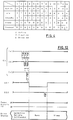
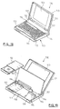
- FIG. 18 An example of portable computer is shown in Fig. 18, in which portable computer 100 has relatively thin body 110 and cover 120, which is coupled to body 110 so that cover 120 can be opened and closed.
- Cover 120 has shallow case 121. At the bottom of case 121 a pair of cylindrical protrusions 122 is formed integrally with the case. With the pair of protrusions 122 rotatable supported with respect to the body, cover 120 is hinged on body 110, allowing cover 120 to be opened or closed with respect to body 110 with an axis of protrusions 122. In the central portion of the open side, i.e. back side, of the cover, liquid crystal display or LCD123 is provided as a display means of the personal computer (hereinafter the cover is generically called LCD120).
- LCD120 liquid crystal display or LCD123
- Body 110 has a shallow case 111 to which support plate 112 of a given width is attached to cover the rear portion of the upper opening of case 111.
- keyboard 113 is placed as an input means of the personal computer.
- a pair of tongue protrusions 114 is formed integrally with keyboard 113. With the pair of protrusions 114 supported axially with the front edge of support plate 112, keyboard 113 is hinged on plate 112. This allows keyboard 113 to be opened or closed with respect to case 111 with an axis of protrusions 114, and the interior of case 111 is exposed when keyboard 113 is opened.
- Opening or closing of LCD120 with respect to body 110 and that of keyboard 113 with respect to case 111 is accomplished by two step operation on open/close control 115 provided on a side of case 111. Since closing LCD120 or opening keyboard 113 will disable computer 100, mechanical operations such as LCD close and keyboard open are electrically converted into CPU interrupt factors.
- Fig. 19 shows the exposed interior of case 111 with keyboard 113 being opened.
- partition 116 is provided to separate the front portion of case 111 from its rear portion.
- Partition 116 may be formed of a thin metal plate by a bending process.
- internal circuits (not shown) of the personal computer including CPU, ROM, RAM and system bus.
- the larger space in front of partition 116 is provided to accommodate expansion devices, such as floppy disk drive (FDD) pack 117 and hard disk drive (HDD) pack 119 and battery pack 118.
- FDD floppy disk drive
- HDD hard disk drive
- battery pack 118 Provided on a side of partition 116 are connectors (not shown) which comply with respective standards for the internal circuits of portable computer 100 to electrically connect these packs with the circuits.
- FDD pack 117 or HDD pack 118 be used exchangeable with other detachable expansion devices.
- FDD pack 117 could be removed from the space in the front portion of case 111 to substitute CDROM drive pack 50.
- CDROM Compact Disk Read Only Memory
- CDROM Compact Disk Read Only Memory
- CDROM has been used to record a great quantity of information such as text data and program data, as well as audio and image data (including pictures, animation and computer graphics).
- Power save is "Suspend", which is to be powered down to almost all portions except main memory for power save when a predetermined state occurs in which an I/O device activity has not been detected for a certain period of time or closing of an LCD (cover) is detected.
- the data necessary for restarting a task such as the hardware context information including I/O configuration and CPU status and the contents of VRAM, is saved in main memory.
- the operation for restarting power supply to exit from the suspend mode for recovery is called “Resume”.
- the resume mode the data previously saved in main memory is restored to each component to enable a task to be restarted from the same point as that of powered down.
- This series of power management operations is actually executed by a program such as those which is called PM code (PMC) or Advanced PM (APM), which is a trademark of Astek International.
- PM code PM code
- API Advanced PM
- One challenge encountered in developing a power management technique is how can a task be resumed quickly and from precisely the same point of execution as of interruption upon recovery from the power save mode such as suspend.
- the portable computer body (hereinafter called host) saves the system information which was present immediately before suspend, such as the hardware context information including register values of each chip and the contents of VRAM, in main memory to preserve the "same point of execution" for the host.
- system information such as the hardware context information including register values of each chip and the contents of VRAM
- the host does not consider the status of the expansion device, but consider only itself, that is, whether it has preserved the "same point of execution" to effect powered down.
- the expansion device can be divided into the one which has no CPU, e.g. floppy disk drive or FDD, and the other which has a build in CPU, e.g. hard disk or HDD and CDROM drive. Operation of the former type is controlled by a controller circuit provided within the host, such as floppy disk controller or FDC. In such cases, the host could preserve the status of FDD immediately before transition to suspend, i.e., the "same point of execution", by managing FDC.
- a controller circuit provided within the host, such as floppy disk controller or FDC.
- the host could preserve the status of FDD immediately before transition to suspend, i.e., the "same point of execution", by managing FDC.
- This type of expansion device includes ROM for storing various types of firmware and RAM as working area of CPU.
- the host operating system or OS does not directly control the expansion device, but only issues an instruction in a form of command to the CPU of the expansion device.
- the CPU of the expansion device interprets the command from the host in accordance with the firmware in ROM and performs actual tasks by using RAM as working area.
- the host OS is not required to directly control all components within the expansion device, and typically has not such function. In these environments, if the host references only the status of itself to be powered down, operation results, e.g. the contents of RAM, on the expansion device will be lost (i.e., because the host has nothing to do against it!), and the lost contents of storage cannot be recovered even if power is supplied again from the host.
- the RAM at the CDROM drive has recorded various information on the disk being inserted.
- This information includes data allocation information such as Table of Contents or TOC, drive parameters indicating data rates, and audio parameters indicating audio output levels.
- TOC information is necessary for searching recording positions during playback of the disk, and is retained when the disk contents are read into RAM during its insertion until either the disk is removed, or power on reset (POR) is done.
- POR power on reset
- Each value of drive and audio parameters is dynamically updated during processing of commands from the host. However, if power supply is suspended only for the convenience of the host, such data in RAM will be lost.
- the TOC information As with normal Power On Reset (POR), must be read again from the disk.
- the CDROM drive has an average access time of as long as 350 milliseconds, requiring seconds or tens of seconds even for reading the TOC information.
- the compact disk usually manages information for each session. The TOC is provided for every session and recorded in the Lead In at the beginning of each session. The TOC has a size of 512 bytes per session. For the disk which consists of multiple sessions, the time required for reading operation will be longer as the number of TOCs increases.) The time duration from several seconds to tens of seconds is too long for the user to wait, taking a random look at the display.
- the CDROM With its high capacity, the CDROM, among others, is often used for providing long programs such as roll playing game, and the user is likely to close the LCD many times to stop a game until the program ends.
- the problem of the resume mode i.e. restarting a task quickly from the same point of execution, becomes more severe.
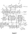
- Fig. 1 is a block diagram of part of the hardware organization of a computer system in which the present invention is embodied.
- Fig. 2 is the hardware organization of a CDROM drive in which the present invention is embodied.
- Fig. 3 is a schematic illustration which shows the operation modes of a CDROM drive.
- Fig. 4 is a schematic illustration which shows activities in the CDROM drive in each operation mode.
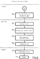
- Fig. 5 is a flow diagram illustrating operation of the CDROM drive during normal power on (POR) by the host.
- Fig. 6 is a flow diagram illustrating operation of the CDROM drive during transition to sleep by an internal timer of drive.
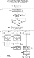
- Fig. 7 is a flow diagram illustrating operation of the CDROM drive during transition to sleep by an instruction of the host.
- Fig. 8 is a flow diagram illustrating operation of the CDROM drive during wake up from sleep.
- Fig. 9 is a flow diagram illustrating operation of the CDROM drive during transition from active, idle or standby to suspend mode.
- Fig. 10 is a flow diagram illustrating operation of the CDROM drive during transition from sleep to suspend mode.
- Fig. 11 is a flow diagram illustrating operation of the CDROM drive during resume from suspend mode.
- Fig. 12 illustrates operation of host control and drive status signals when a sleep request by the host control signal causes transition from active, idle or standby to sleep mode.
- Fig. 13 illustrates operation of host control and drive status signals during wake up from sleep.
- Fig. 14 illustrates operation of host control and drive status signals when a suspend request by the host control signal causes transition from active, idle or standby to suspend mode.
- Fig. 15 illustrates operation of host control and drive status signals during transition from sleep to suspend mode.
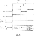
- Fig. 16 illustrates operation of host control and drive status signals during resume from suspend mode.
- Fig. 17 is the hardware configuration of a magneto optical disk drive.
- Fig. 18 is an isometric view of a portable computer, and particularly illustrating a usable state with LCD opened.
- Fig. 19 is an isometric view of the portable computer, and particularly illustrating a state in which the case interior is exposed with LCD and the keyboard opened.
- main CPU70 is electrically connected with each unit within the system via system bus 80 so that it controls the operation of the whole system 100.
- Sub CPU60 is provided to support main CPU70 in power management.
- main CPU70, sub CPU60 and system bus 80 should be considered to make up a host.
- CDROM drive (hereinafter also referred to as drive) 50 is connected to main CPU70 through system bus 80 so that it can send to or receive commands from the host.
- Drive 50 is also connected with sub CPU60 through host Control Signal (hereinafter also referred to as CS) 19 and two drive Status Signals (also called SS1 and SS2) 20. The function of signals 19 and 20 will be later described.
- CS host Control Signal
- SS1 and SS2 drive Status Signals
- expansion devices such as FDD and HDD.
- main CPU70 is interrupted to enter the suspend mode.
- a suspend request is raised under control of PM code (PMC) 71.
- PMC PM code
- main CPU70 requests suspend from drive 50 by using a command via system bus 80.
- a suspend request arises under control of APM61.
- sub CPU60 requests suspend from CPU10 in drive 50 via host control signal 19. (The transfer of a suspend request using a host control signal will be described later.)
- PMC71 can be the one which is loaded from system ROM (not shown) during POR and can be the other which is incorporated in the operating system (OS). What is important in the present embodiment, however, is not the operation of power management itself by PMC or APM at the host, but that a suspend request is made by the host to drive 50 in a form of either command or control signal.
- Fig. 2 is a detailed block diagram illustrating the hardware organization of CDROM drive 50 shown in Fig. 1. It should be understood by the following description that the present invention is embodied by using CDROM drive 50.
- Disk (CD) 21 as a storage medium is rotatable mounted onto spindle motor 5. Beneath the surface of disk 21 is located Pick Up Head 1. Motor drive circuit 4 controls the rotation of spindle motor 5 so that the track of disk 21 rotates at a constant linear velocity (CLV) with respect to pick up head 1.
- CLV constant linear velocity
- Pick up head 1 is used for read data using the output of laser to disk 21 and reception of reflected light, and is mounted onto slider motor 6 which is movable in the radial direction of disk 21.
- the output signal from pick up head 1 is input to servo circuit/digital signal processing circuit 3 via RF amplifier 2 for both position control of pick up head 1 and data processing.
- a control system which is made up of servo circuit 3 and motor drive circuit 4 controls synchronous driving of spindle motor 5 and slider motor 6 based on that output signal to enable pick up head 1 to access disk 21.
- Pick up head 1 is supported by a two axis device (not shown) which is capable of precision driving and focus and tracking adjustable.
- the output signal is processed by digital signal processing circuit (DSP) 3.
- DSP digital signal processing circuit
- DAC digital/analog converter circuit
- the signal is output via DAC7 and audio amplifier circuit 8.
- decoder circuit 9 decodes the signal to send it to system bus 80.
- the servo circuit and DSP are shown with identical reference numeral 3, and may be of the same chip or of separate chips.
- a tray (not shown) for mechanically mounting disk 21 is coupled with loading motor 12 in a power transferrable manner.
- Motor drive circuit 11 controls loading motor 12 in response to a signal from eject button 18 which is used to indicate tray open or close operation or a request from CPU10 (or request from the host via CPU10), thus allowing replacement of disk 21.
- CPU10 is a controller means for controlling the operation of each unit within CDROM drive 50.
- CPU10 includes clock 14 for synchronizing operations, ROM16, RAM15 and Electrically Erasable Programmable ROM (EEPROM) 17.
- EEPROM Electrically Erasable Programmable ROM
- ROM16 is a read only memory with its write data determined during manufacture and is used to store various types of firmware.
- the actual firmware to be stored is used for self test performed by drive 50 during start up (POR), command processing for interpreting commands sent from the host (also called host command), checking drive status such as disk in/out and tray open/close, or mechanical control for controlling the drive mechanism such as tray eject.
- RAM15 is first data saving means used by CPU10 as working area and, as described in the introduction above, is used to store various information on the disk 21 being inserted (e.g. allocation information such as TOC, drive parameters indicating data rates, audio parameters indicating audio output levels).
- allocation information such as TOC, drive parameters indicating data rates, audio parameters indicating audio output levels.
- DRAM Dynamic RAM
- SRAM Static RAM
- SRAM is preferred (the reason of which will be described later).
- EEPROM17 is a write-enable non-volatile semiconductor memory and acts as second data saving means, details of which described below.
- Interface circuit 9 is used to control the flow of data between the host and drive 50 and includes a control register, command register, status register, error register and data register.
- the status register includes a field for retaining the current operation mode of drive 50 (operation modes of drive 50 will be described in section C) and a Busy Flag for presenting an Activity of drive 50 to the host.
- the activity of drive 50 can be a Ready state in which a host command can be executed immediately or a Busy state in which no host command can be accepted due to processing of a task.
- the host OS can recognize the status of drive 50 by polling this status register.
- Interface and decoding circuits are shown in Fig. 2 with identical reference numeral 9, and may be configured with the same chip or separate chips.
- communications between CPU10 of drive 50 and the host are performed with commands send or received via interface circuit 9, and also with host control signal 19 and drive status signal 20.
- Host control signal 19 is a signal used by the host to communicate its intention to drive 50 and provided for two purposes in this embodiment. One is to send a request from the host for changing operation mode. Another is to initiate hardware interrupt to CPU10 while clock 14 is in halted. As described in section C, CDROM drive 50 can enter an operation mode of sleep or suspend where clock 14 of CPU10 is in a halt state.
- Halted clock 14 causes interface circuit 9 to stop and accept no command. Therefore, interruption of CPU 10 by host control signal 19 activates clock 14.
- drive status signal 20 is a signal used by drive 50 to communicate its intention to the host, and consists of two signal lines SS1 and SS2, as described above.
- SS1 indicates the activity of drive 50 with a High or Low level of signal.
- SS2 is used to notify the host that drive 50 moves voluntarily from active, idle or standby to sleep mode (see section D.2).
- drive 50 is supplied with power from the host, as shown with an arrow of reference numeral 13, detailed power lines are not shown. It should be noted, however, that turning on or off this power supply 13 is caused by normal power on (POR) or power off at the host and also dependent upon suspend/resume operation.
- POR power on
- CDROM drive 50 has five operation modes: Active, Idle, Standby, Sleep and Suspend.
- Fig. 3 schematically shows each operation mode and transitions between them. Transition between each mode is triggered by an internal timer of drive 50, a request by a host command or host control signal, application of power from the host for resume, or normal application or suspension of power (POR) by the host.
- each transition is represented by an arrow indicating a trigger. The procedure of transition to each operation mode depends on its trigger and will be described in detail in section D.
- each mechanism and electrical circuit within drive 50 varies between operation modes, and their relationship is shown in Fig. 4.
- column headings indicate components of drive 50 (the numbers in column headings correspond to reference numerals in Fig. 2), and row headings indicate operation modes.
- Characters A (Active), I (Inactive) and D (Disabled) in each column of the table denote the activity state in the corresponding operation mode of each component, and the activity level descends in this order; A, I and D.
- CDROM drive 50 may enter the other modes not with a host command but with host control signal 19.
- the intention of the host may communicate only with host control signal 19 because the halt of clock 14 of CPU10 inhibits reception of the host command.
- host control signal (CS) 19 acts in cooperation with drive status signals 20 (SS1 and SS2). This section will describe the relationship between each signal line and the operation of drive 50 with reference to Figs. 12 to 16. In each timing diagram shown in Figs.
- the first line denotes the signal level of host control signal (CS) 19
- the second line the signal level of drive status signal SS1
- the third line the signal level of drive status signal SS2
- the fourth line the voltage level of supply power from the host and the fifth line the operation mode of drive 50.
- the preferred embodiment of the present invention uses a CDROM drive.
- magneto optical disks which are similar to CDROM drives in structure and effects, also have problems which can be addressed by the present invention. This section will briefly describe that the present invention can also be practised in relation to magneto optical disk drives.
- Fig. 17 shows the hardware configuration of magneto optical disk drive 51 in which the present invention is practised. Identical reference numbers indicate similar components to those shown in Fig. 2.
- Magneto optical disk drive 51 differs from CDROM drive 50 in that drive 51 further includes magnetic coil 25 for write operation to magneto optical (MO) disk 26, drive circuit 22 for driving magnetic coil 25, analog/digital converter circuit (ADC) 24 for converting analog input into digital signals and encoder circuit 23 for encoding signals.
- MO magneto optical
- ADC analog/digital converter circuit
- an expansion device detachably installed into a computer system (host) and capable of quickly and exactly in response to a series of operations for power management at the host. Furthermore, it is possible to provide an environment for a portable computer system wherein the expansion device itself saves the information which is required during resume operation and cannot be managed at the host when the suspend mode is entered, thereby allowing a task to be restarted quickly and from precisely the same point of execution during resume.
Abstract
Description
- The present invention relates to an expansion device detachably installed into a portable computer system, such as "notebook" type computer.
- Specifically, the present invention relates to an expansion device which is capable of resuming a task quickly and precisely from the same point of execution when a computer system turns power on again after suspending power supply to its components for saving power.
- Recent advancements in technologies has resulted in a widespread use of portable or "notebook" type computers designed to have a small size and light weight for portability.
- An example of portable computer is shown in Fig. 18, in which
portable computer 100 has relatively thin body 110 andcover 120, which is coupled to body 110 so thatcover 120 can be opened and closed. -
Cover 120 hasshallow case 121. At the bottom of case 121 a pair ofcylindrical protrusions 122 is formed integrally with the case. With the pair ofprotrusions 122 rotatable supported with respect to the body,cover 120 is hinged on body 110, allowingcover 120 to be opened or closed with respect to body 110 with an axis ofprotrusions 122. In the central portion of the open side, i.e. back side, of the cover, liquid crystal display or LCD123 is provided as a display means of the personal computer (hereinafter the cover is generically called LCD120). - Body 110 has a shallow case 111 to which support
plate 112 of a given width is attached to cover the rear portion of the upper opening of case 111. At the front portion of the upper opening,keyboard 113 is placed as an input means of the personal computer. At the back edge ofkeyboard 113, a pair oftongue protrusions 114 is formed integrally withkeyboard 113. With the pair ofprotrusions 114 supported axially with the front edge ofsupport plate 112,keyboard 113 is hinged onplate 112. This allowskeyboard 113 to be opened or closed with respect to case 111 with an axis ofprotrusions 114, and the interior of case 111 is exposed whenkeyboard 113 is opened. Opening or closing of LCD120 with respect to body 110 and that ofkeyboard 113 with respect to case 111 is accomplished by two step operation on open/close control 115 provided on a side of case 111. Since closing LCD120 or openingkeyboard 113 will disablecomputer 100, mechanical operations such as LCD close and keyboard open are electrically converted into CPU interrupt factors. - Fig. 19 shows the exposed interior of case 111 with
keyboard 113 being opened. At near central portion of case 111, partition 116 is provided to separate the front portion of case 111 from its rear portion. Partition 116 may be formed of a thin metal plate by a bending process. In the rear portion of case 111 which is enclosed by partition 116, there is accommodated internal circuits (not shown) of the personal computer including CPU, ROM, RAM and system bus. The larger space in front of partition 116 is provided to accommodate expansion devices, such as floppy disk drive (FDD)pack 117 and hard disk drive (HDD)pack 119 andbattery pack 118. Provided on a side of partition 116 are connectors (not shown) which comply with respective standards for the internal circuits ofportable computer 100 to electrically connect these packs with the circuits. - As a new concept for such
portable computer 100, there has been suggested that FDDpack 117 orHDD pack 118 be used exchangeable with other detachable expansion devices. For example, FDDpack 117 could be removed from the space in the front portion of case 111 to substituteCDROM drive pack 50. The term CDROM (Compact Disk Read Only Memory), as used herein, is meant to be an optical disk of aluminum reflective film type, and particularly a storage medium used only for playback which stores information by making use of the fact that depressions on the surface of the disk cause variation of the intensity of reflected light. Capable of high density recording, CDROM has been used to record a great quantity of information such as text data and program data, as well as audio and image data (including pictures, animation and computer graphics). By incorporating a CDROM drive having such data playback function, the portable computer as a new medium (or multimedia) is expected to be widely used in fields including education and entertainment. - One of the purposes for which the portable computer is developed is outdoor use in a portable manner. Typically, power supply is therefore not dependent on a constant AC source, but on a battery pack (particularly NiCd, NiMH or LiIon rechargeable battery), as shown in Fig. 19. However, the battery pack is limited to the type of small size, light weight and short lifetime. Consequently, measures have been taken in recent portable computers for Power Management or Power Save.
- One example of power save is "Suspend", which is to be powered down to almost all portions except main memory for power save when a predetermined state occurs in which an I/O device activity has not been detected for a certain period of time or closing of an LCD (cover) is detected. Before the suspend mode is entered, the data necessary for restarting a task, such as the hardware context information including I/O configuration and CPU status and the contents of VRAM, is saved in main memory. On the other hand, the operation for restarting power supply to exit from the suspend mode for recovery is called "Resume". In the resume mode, the data previously saved in main memory is restored to each component to enable a task to be restarted from the same point as that of powered down. This series of power management operations is actually executed by a program such as those which is called PM code (PMC) or Advanced PM (APM), which is a trademark of Astek International.
- One challenge encountered in developing a power management technique is how can a task be resumed quickly and from precisely the same point of execution as of interruption upon recovery from the power save mode such as suspend.
- As described above, the portable computer body (hereinafter called host) saves the system information which was present immediately before suspend, such as the hardware context information including register values of each chip and the contents of VRAM, in main memory to preserve the "same point of execution" for the host.
- For the expansion device, on the other hand, only information to be provided when the host enters the suspend mode is "power down". In other words, the host does not consider the status of the expansion device, but consider only itself, that is, whether it has preserved the "same point of execution" to effect powered down.
- From a point of view, the expansion device can be divided into the one which has no CPU, e.g. floppy disk drive or FDD, and the other which has a build in CPU, e.g. hard disk or HDD and CDROM drive. Operation of the former type is controlled by a controller circuit provided within the host, such as floppy disk controller or FDC. In such cases, the host could preserve the status of FDD immediately before transition to suspend, i.e., the "same point of execution", by managing FDC.
- However, the case is different in the expansion device having a built in CPU. This type of expansion device includes ROM for storing various types of firmware and RAM as working area of CPU. The host operating system or OS, does not directly control the expansion device, but only issues an instruction in a form of command to the CPU of the expansion device. The CPU of the expansion device interprets the command from the host in accordance with the firmware in ROM and performs actual tasks by using RAM as working area. The host OS is not required to directly control all components within the expansion device, and typically has not such function. In these environments, if the host references only the status of itself to be powered down, operation results, e.g. the contents of RAM, on the expansion device will be lost (i.e., because the host has nothing to do against it!), and the lost contents of storage cannot be recovered even if power is supplied again from the host.
- From the descriptions above, those skilled in the art will readily appreciate that conventional host computers cannot restart a task from precisely the same point of execution.
- Problems which arise when the status immediately before transition to the suspend mode is lost at the expansion device will now be briefly described with an example of CDROM drive.
- The RAM at the CDROM drive has recorded various information on the disk being inserted. This information includes data allocation information such as Table of Contents or TOC, drive parameters indicating data rates, and audio parameters indicating audio output levels. Among these, the TOC information is necessary for searching recording positions during playback of the disk, and is retained when the disk contents are read into RAM during its insertion until either the disk is removed, or power on reset (POR) is done. Each value of drive and audio parameters is dynamically updated during processing of commands from the host. However, if power supply is suspended only for the convenience of the host, such data in RAM will be lost.
- Once these working data in RAM is lost, some disadvantages are found during resume operation. Of these, the TOC information, as with normal Power On Reset (POR), must be read again from the disk. However, the CDROM drive has an average access time of as long as 350 milliseconds, requiring seconds or tens of seconds even for reading the TOC information. (The compact disk usually manages information for each session. The TOC is provided for every session and recorded in the Lead In at the beginning of each session. The TOC has a size of 512 bytes per session. For the disk which consists of multiple sessions, the time required for reading operation will be longer as the number of TOCs increases.) The time duration from several seconds to tens of seconds is too long for the user to wait, taking a random look at the display. In such situations, the user may have wrong or unfavourable impressions, like "the computer is not good enough to use" or "the machine might have gone trouble". In addition, drive and audio parameters must be specified again, as with normal POR. In such case, the context of the task is destroyed, e.g. the disk is played back with a different audio level. This gives the user a sense of incompatibility. Briefly, playback of the CDROM is not restarted from the same point of execution. Similar problems might arise during wake up after hibernation. (For details of the hibernation technique for computer systems, refer to Japanese patent application 5-184186.)
- With its high capacity, the CDROM, among others, is often used for providing long programs such as roll playing game, and the user is likely to close the LCD many times to stop a game until the program ends. Thus the problem of the resume mode, i.e. restarting a task quickly from the same point of execution, becomes more severe.
- Such problem during the resume mode, however, is unlikely to occur with the HDD since its average access time is as relatively short as approximately 12 milliseconds. For the magneto optical (MO) disk drive, the average access time is as slightly longer as 32 milliseconds at most (for thick drives. With a built in type MO drive, the access time further increases as the feed motor size is reduced.), the problem of resuming being as severe as for the CDROM drive.
- From the foregoing it should be readily apparent to those skilled in the art that there is required information for restarting a task from the suspend mode at the host, and similarly, that there is also required information for restarting the task at the device, especially at the one having its own CPU. Moreover, it should also be apparent to those skilled in the art that the host cannot control all the information required by the device for resuming. However, if no provision is available for managing the information at the expansion device, a longer period of time will be necessary for restarting a task and the context of the task will be lost.
- It is therefore an object of the present invention to provide an expansion device which itself saves the information which is required during resume operation and cannot be managed at the host when the suspend mode is entered, thereby allowing a task to be restarted quickly and from precisely the same point of execution during resume.
- This object is achieved by the invention claimed in
claim 1. - An embodiment of the invention will now be described, by way of example, with reference to the accompanying drawings, in which:
- Fig. 1 is a block diagram of part of the hardware organization of a computer system in which the present invention is embodied.
- Fig. 2 is the hardware organization of a CDROM drive in which the present invention is embodied.
- Fig. 3 is a schematic illustration which shows the operation modes of a CDROM drive.
- Fig. 4 is a schematic illustration which shows activities in the CDROM drive in each operation mode.
- Fig. 5 is a flow diagram illustrating operation of the CDROM drive during normal power on (POR) by the host.
- Fig. 6 is a flow diagram illustrating operation of the CDROM drive during transition to sleep by an internal timer of drive.
- Fig. 7 is a flow diagram illustrating operation of the CDROM drive during transition to sleep by an instruction of the host.
- Fig. 8 is a flow diagram illustrating operation of the CDROM drive during wake up from sleep.
- Fig. 9 is a flow diagram illustrating operation of the CDROM drive during transition from active, idle or standby to suspend mode.
- Fig. 10 is a flow diagram illustrating operation of the CDROM drive during transition from sleep to suspend mode.
- Fig. 11 is a flow diagram illustrating operation of the CDROM drive during resume from suspend mode.
- Fig. 12 illustrates operation of host control and drive status signals when a sleep request by the host control signal causes transition from active, idle or standby to sleep mode.
- Fig. 13 illustrates operation of host control and drive status signals during wake up from sleep.
- Fig. 14 illustrates operation of host control and drive status signals when a suspend request by the host control signal causes transition from active, idle or standby to suspend mode.
- Fig. 15 illustrates operation of host control and drive status signals during transition from sleep to suspend mode.
- Fig. 16 illustrates operation of host control and drive status signals during resume from suspend mode.
- Fig. 17 is the hardware configuration of a magneto optical disk drive.
- Fig. 18 is an isometric view of a portable computer, and particularly illustrating a usable state with LCD opened.
- Fig. 19 is an isometric view of the portable computer, and particularly illustrating a state in which the case interior is exposed with LCD and the keyboard opened.
- A preferred embodiment of the present invention will now be described under the following headings:
- A. Organization of a portable computer system
- B. Hardware organization of a CDROM drive
- C. Operation modes of the CDROM drive
- C.1. Active mode
- C.2. Idle mode
- C.3. Standby mode
- C.4. Sleep mode
- C.5. Suspend mode
- D. Procedure of transition to respective operation modes of CDROM drive
- D.1. Normal power on reset (POR)
- D.1.1. Processing at the host
- D.1.2. Processing at the CDROM drive
- D.2. Transition to sleep mode using an internal timer of the drive
- D.3. Transition to sleep mode upon request from the host
- D.4. Return from sleep mode (wake up)
- D.5. Transition from active, idle and standby to suspend mode
- D.6. Transition from sleep to suspend mode
- D.7. Recovery from suspend mode (resume)
- D.1. Normal power on reset (POR)
- E. Timing diagram of the operation of host control and drive status signals
- E.1. Transition from active, idle and standby to sleep mode
- E.2. Wake up from sleep mode
- E.3. Transition from active, idle and standby to suspend mode
- E.4. Transition from sleep to suspend mode
- E.5. Resume from suspend mode
- F. Application to magneto optical disk
- In Fig. 1, main CPU70 is electrically connected with each unit within the system via
system bus 80 so that it controls the operation of thewhole system 100. Sub CPU60 is provided to support main CPU70 in power management. Within the system shown in Fig. 1, main CPU70, sub CPU60 andsystem bus 80 should be considered to make up a host. - CDROM drive (hereinafter also referred to as drive) 50 is connected to main CPU70 through
system bus 80 so that it can send to or receive commands from the host.Drive 50 is also connected with sub CPU60 through host Control Signal (hereinafter also referred to as CS) 19 and two drive Status Signals (also called SS1 and SS2) 20. The function ofsignals - Connected to
system bus 80 are expansion devices such as FDD and HDD. - At the host, when a specified event indicating that a task cannot continue, such as "LCD close", "keyboard open", and "battery discharged", is detected, main CPU70 is interrupted to enter the suspend mode. There are two types of requests from the host to drive 50 for transition to the suspend mode. In one type, a suspend request is raised under control of PM code (PMC) 71. In this case, main CPU70 requests suspend from
drive 50 by using a command viasystem bus 80. In another type of transition request, a suspend request arises under control of APM61. In this case, sub CPU60 requests suspend from CPU10 indrive 50 viahost control signal 19. (The transfer of a suspend request using a host control signal will be described later.) - PMC71 can be the one which is loaded from system ROM (not shown) during POR and can be the other which is incorporated in the operating system (OS). What is important in the present embodiment, however, is not the operation of power management itself by PMC or APM at the host, but that a suspend request is made by the host to drive 50 in a form of either command or control signal.
- Fig. 2 is a detailed block diagram illustrating the hardware organization of CDROM drive 50 shown in Fig. 1. It should be understood by the following description that the present invention is embodied by using
CDROM drive 50. - Disk (CD) 21 as a storage medium is rotatable mounted onto
spindle motor 5. Beneath the surface ofdisk 21 is locatedPick Up Head 1.Motor drive circuit 4 controls the rotation ofspindle motor 5 so that the track ofdisk 21 rotates at a constant linear velocity (CLV) with respect to pick uphead 1. - Pick up
head 1 is used for read data using the output of laser todisk 21 and reception of reflected light, and is mounted ontoslider motor 6 which is movable in the radial direction ofdisk 21. - The output signal from pick up
head 1 is input to servo circuit/digitalsignal processing circuit 3 viaRF amplifier 2 for both position control of pick uphead 1 and data processing. For position control, a control system which is made up ofservo circuit 3 andmotor drive circuit 4 controls synchronous driving ofspindle motor 5 andslider motor 6 based on that output signal to enable pick uphead 1 to accessdisk 21. Pick uphead 1 is supported by a two axis device (not shown) which is capable of precision driving and focus and tracking adjustable. For data processing, the output signal is processed by digital signal processing circuit (DSP) 3. To send a processed digital signal to the host, digital/analog converter circuit (DAC) 7 converts the signal into an analog for output. For output to a headphone, the signal is output via DAC7 andaudio amplifier circuit 8. When the signal is output as digital data to the host,decoder circuit 9 decodes the signal to send it tosystem bus 80. The servo circuit and DSP are shown withidentical reference numeral 3, and may be of the same chip or of separate chips. - A tray (not shown) for mechanically mounting
disk 21 is coupled with loadingmotor 12 in a power transferrable manner.Motor drive circuit 11controls loading motor 12 in response to a signal fromeject button 18 which is used to indicate tray open or close operation or a request from CPU10 (or request from the host via CPU10), thus allowing replacement ofdisk 21. - CPU10 is a controller means for controlling the operation of each unit within
CDROM drive 50. CPU10 includesclock 14 for synchronizing operations, ROM16, RAM15 and Electrically Erasable Programmable ROM (EEPROM) 17. - ROM16 is a read only memory with its write data determined during manufacture and is used to store various types of firmware. The actual firmware to be stored is used for self test performed by
drive 50 during start up (POR), command processing for interpreting commands sent from the host (also called host command), checking drive status such as disk in/out and tray open/close, or mechanical control for controlling the drive mechanism such as tray eject. - RAM15 is first data saving means used by CPU10 as working area and, as described in the introduction above, is used to store various information on the
disk 21 being inserted (e.g. allocation information such as TOC, drive parameters indicating data rates, audio parameters indicating audio output levels). There are Dynamic RAM (DRAM) which requires refreshing of stored data and Static RAM (SRAM) which does not require refreshing. In this embodiment, SRAM is preferred (the reason of which will be described later). - EEPROM17 is a write-enable non-volatile semiconductor memory and acts as second data saving means, details of which described below. There are two types of EEPROM: in one type, data can be erased only per bit, and in so called flash memory of another type, data can be fully erased by sector. Although either type can be used as second data saving means, the latter allows more efficient operations.
-
Interface circuit 9 is used to control the flow of data between the host and drive 50 and includes a control register, command register, status register, error register and data register. Of these, the status register includes a field for retaining the current operation mode of drive 50 (operation modes ofdrive 50 will be described in section C) and a Busy Flag for presenting an Activity ofdrive 50 to the host. The activity ofdrive 50 can be a Ready state in which a host command can be executed immediately or a Busy state in which no host command can be accepted due to processing of a task. The host OS can recognize the status ofdrive 50 by polling this status register. Interface and decoding circuits are shown in Fig. 2 withidentical reference numeral 9, and may be configured with the same chip or separate chips. - As described above, communications between CPU10 of
drive 50 and the host are performed with commands send or received viainterface circuit 9, and also withhost control signal 19 and drivestatus signal 20. -
Host control signal 19 is a signal used by the host to communicate its intention to drive 50 and provided for two purposes in this embodiment. One is to send a request from the host for changing operation mode. Another is to initiate hardware interrupt to CPU10 whileclock 14 is in halted. As described in section C, CDROM drive 50 can enter an operation mode of sleep or suspend whereclock 14 of CPU10 is in a halt state. Haltedclock 14causes interface circuit 9 to stop and accept no command. Therefore, interruption ofCPU 10 byhost control signal 19 activatesclock 14. - Conversely, drive
status signal 20 is a signal used bydrive 50 to communicate its intention to the host, and consists of two signal lines SS1 and SS2, as described above. SS1 indicates the activity ofdrive 50 with a High or Low level of signal. (In this embodiment, a busy state causes SS1 to go to a low level.) SS2 is used to notify the host that drive 50 moves voluntarily from active, idle or standby to sleep mode (see section D.2). - Though
drive 50 is supplied with power from the host, as shown with an arrow ofreference numeral 13, detailed power lines are not shown. It should be noted, however, that turning on or off thispower supply 13 is caused by normal power on (POR) or power off at the host and also dependent upon suspend/resume operation. - Operations of
host control signal 19,drive status signal 20 andpower supply 13 will be described in detail in section E. - CDROM drive 50 has five operation modes: Active, Idle, Standby, Sleep and Suspend.
- Fig. 3 schematically shows each operation mode and transitions between them. Transition between each mode is triggered by an internal timer of
drive 50, a request by a host command or host control signal, application of power from the host for resume, or normal application or suspension of power (POR) by the host. In Fig. 3, each transition is represented by an arrow indicating a trigger. The procedure of transition to each operation mode depends on its trigger and will be described in detail in section D. - The state of operation of each mechanism and electrical circuit within
drive 50 varies between operation modes, and their relationship is shown in Fig. 4. In the table shown in Fig. 4, column headings indicate components of drive 50 (the numbers in column headings correspond to reference numerals in Fig. 2), and row headings indicate operation modes. Characters A (Active), I (Inactive) and D (Disabled) in each column of the table denote the activity state in the corresponding operation mode of each component, and the activity level descends in this order; A, I and D. - It should be readily understood in Figs. 3 and 4 that each component within
drive 50 becomes more inactive as the operation mode moves downward. It should also be apparent to those skilled in the art that themore drive 50 becomes inactive, the more power reduction is achieved. - In other words, as the operation mode changes from active to idle, standby, sleep and suspend, drive 50 goes deep into sleep. Each operation mode will now be described.
- C.1. Active mode
Active mode is a state in which power (5V, 500mA, in this embodiment) is normally supplied from the host and the drive is currently executing a self test or host command, or the host command can be immediately executed. - C.2. Idle mode
In idle mode,spindle motor 5 is rotating, but the laser output of pick uphead 1 will stop. This causes output toRF amplifier 2 to be cut off. Then servo control, i.e. position control for pick uphead 1, onslider motor 6 and the two axis device is substantially interrupted. The effect of power save on laser output and servo control is a decrease of power consumption to 300mA.
When a host command is issued in this mode, the active mode can be entered with only a time delay necessary for restarting servo control. - C.3. Standby mode
In standby mode, the rotation ofspindle motor 5 will also stop, i.e.motor drive circuit 4 andspindle motor 5 become more Inactive. This results in decrease in power consumption to 100mA.
When a host command is issued in this mode, the time required for spin up ofspindle motor 5 and restarting servo control allows returning to the active mode. In active, idle and standby modes, drive 50 is in a state in which it can service the host command immediately. - C.4. Sleep mode
Briefly, sleep mode is a state whereclock 14 of CPU10 in halted and all mechanisms and electrical circuits ofdrive 50 are in a complete halt state (Disabled). In this mode, power is still supplied from the host, but its consumption is only of small leak current (10mA), thus leading to a significant power saving.
Whenclock 14 of CPU10 is halted, refreshing of memory will be disabled. Therefore, if RAM15 provided in CPU10 is dynamic RAM, its contents are lost. This embodiment, however, employs static RAM as RAM15, which will retain its contents only with the supply of the aforementioned leak current even in the sleep mode.
Since halted ofclock 14causes interface circuit 9 to be in a complete halt state (Disabled), the command issued by the host will not be processed in this mode. Therefore, the host must issue a request usinghost control signal 19 instead of using a command. (Specifically, a request is made for interrupt of CPU10 to activateclock 14. Refer to section E for details.)
One of the features of power saving which is achieved in idle, standby and sleep modes is thatpower supply 13 itself is not turned on or off to each electrical circuit withindrive 50, but power saving is obtained to the extent of approximately two percents of that in the active mode, i.e. 500mA to 10mA, by sequentially forcing each control system into a substantial halt state. In other words, it is not necessary for the host or drive 50 to exercise frequent control over power supply to each electrical circuit for effecting these power save modes. - C.5. Suspend mode
Suspend mode, if viewed from the host, is to stop power supply to almost all units except the main memory after the data required for restarting a task has been saved in the main memory. In suspend mode, therefore, the power supplied to CDROM drive 50 will be OmA. In this sense, the suspend mode, when viewed from the drive, is not different from a state of normal power off. In suspend mode, the contents of each register andRAM 15 withininterface circuit 9 ofdrive 50 are lost due to volatility.
One of the objectives of the present invention is that how the behaviour ofdrive 50 during transition to the suspend mode, i.e. the state withindrive 50, immediately before powered down, is preserved, and which will be described in detail in section D. -
- D.1. Normal power on reset (POR)
Fig. 5 shows a flow diagram of normal power on procedure (POR). The expansion device is illustrated asCDROM drive 50.
When power is applied at the host (step 202), the host and drive 50 performs the following processing in parallel.- D.1.1. Processing at the host
At the host, Power on Self Test (POST) is performed atstep 204, and the operating system (OS) is loaded to allow the computer system to be operative atstep 206.
Then, a Device Driver is run atstep 208. Typically, the device driver to be used has been specified in the "config.sys" file.
Atdecision block 210, a command is sent to the interface circuit at the expansion device (including drive 50) to determine whether connection has actually been established. The expansion device which fails in connection is then treated as being disconnected, as shown with a No branch ofdecision block 210.
When, on the other hand, this attempt has been successful, a further command is sent to the expansion device to confirm drive activity or specify parameters atstep 212, as shown with a Yes branch ofdecision block 210. Drive activity refers to a state whetherdrive 50 is currently processing a task (i.e. busy state) or not, and can be detected by the signal level of drive status signal SS1 (refer to previous description and section E). Parameters include audio (audio output levels) and drive parameters (set time of the power save timer) (see section D.2), rotation speed of the spindle motor and data rate described above. The device driver, when specifying these parameters, notifydrive 50 of each specified value, as shown with arrow 230 (such notification is not made if drive 50 itself specifies default values). - D.1.2. Processing at the CDROM drive
AtCDROM drive 50, first, self diagnostic test is performed atstep 214. The firmware for self test is stored in ROM16 ofdrive 50, as described above. If the self test fails, steps 216, 218, 220 and 222 are skipped to end initialization (step 224).
When, on the other hand, the self test has been successful,step 216 is entered to determine if a disk has already been inserted into the disk tray. If not, steps 218, 220 and 222 are skipped to end initialization (step 224).
If the disk has already been inserted,step 218 is entered to disable ejection of the disk for disk access(specifically, the eject function of the disk tray is killed). Next, atstep 220, the disk is accessed and an attempt is made to read the TOC information. If the read attempt fails,step 222 is skipped to end initialization (step 224).
If read operation is successful, the TOC information is recorded in RAM15 withindrive 50 atstep 222 to terminate the process for initialization (step 224). The TOC information being recorded is retained in RAM15 until the disk is replaced or power on reset (POR). The TOC information is used for illegal request error processing or searching recording positions for which a disk access request occurs (in case of music CDs).
When initialization is ended, disk eject is enabled atstep 226.
When the processing described above ends at the host and drive 50 (step 228), an active state is entered.Drive 50, therefore, is then in a state that it can execute a host command immediately.
- D.1.1. Processing at the host
- D.2. Transition to sleep mode using an internal timer of the
drive CDROM drive 50 can voluntarily enter the sleep mode without receiving a request from the host. Specifically, the internal timer (not shown in Fig. 2) ofdrive 50 monitors the elapsed time from the last disk access, and drive 50, whenever a given period of time is exceeded, automatically enters the idle, standby or sleep mode. Fig. 6 shows a procedure for transition to sleep using the internal timer.
Until a given period is elapsed from the last disk access, the active mode is maintained by the loop formed ofsteps
When a given period of time passes, laser output of pick uphead 1 is stopped and servo control such as for slider motor 6 (step 306) is set to halt to enter the idle mode (step 308). Details of the idle mode has been described in section C.2 above.
During the time between the last disk access and the next given period of time, the idle mode is maintained by the loop formed ofsteps
When the next given period of time passes, the rotation ofspindle motor 5 stops (step 312) and the standby mode is entered (step 314). Refer to section C.3 above for details of this mode.
During the time between the last disk access and the third predetermined period of time, the standby mode is maintained by the loop formed ofsteps
When the fourth predetermined time passes,step 320 is taken andclock 14 of CPU10 is halted to enter the sleep mode. Refer to section C.4 above for details of the sleep mode. Since haltedclock 14causes interface circuit 9 to stop, transition ofdrive 50 to the sleep mode becomes invisible to the host. (In each mode from active to standby, the host can recognize the mode ofdrive 50 by polling the status register withininterface circuit 9. The OS of the host, therefore, can recognize the operation mode ofdrive 50, as described above.) Then, drive 50 notifies the host via drive status signal SS2 of entering the sleep mode before the actual transition (step 318). For details of notification using drive status signal SS2, refer to section E.
Thus, CDROM drive 50 can achieve power save by itself going deep into sleep without waiting a request from the host.
Each predetermined time period before transition to each mode (steps - D.3. Transition to sleep mode upon request from the host In contrast to D.2, the drive may change from the active, idle or standby to sleep mode upon request by a host command or
host control signal 19. Fig. 7 shows a procedure of transition to sleep by an instruction of the host.
The host uses its internal timer (not shown in Fig. 1) to monitor the elapsed time from the last drive access (steps 402 and 404). It determines the activity ofdrive 50 when a predetermined time period passes from the last drive access (step 406). This determination is made by checking the busy flag ofinterface circuit 9 or the signal level of drive status signal SS1, as described above. If the activity is determined as a busy state, the host waits untildrive 50 becomes a ready state. When the ready state is entered, the host sends a sleep request command to drive 50 viasystem bus 80 or requests sleep using host control signal 19 (step 408). For details of sleep request byhost control signal 19, refer to section E.
Drive 50, upon receiving the sleep request from the host, performs a procedure dependent on the current operation mode.
Drive 50, when it enters the active mode, sets atstep 412 the busy flag ofinterface circuit 9 and disables the ejection of the disk, i.e. sets a state in which other task requests are negated. Next, atstep 414, drive 50 stops servo control for the laser output of pick uphead 1,slider motor 6 and the like to enter the idle state before proceeding to step 420.
When drive 50 is in the idle mode, it first atstep 416 sets the busy flag and disables the ejection of the disk (equivalent to step 412). Next atstep 420 it stops rotation ofspindle motor 5 to enter a standby state. At this time, drive 50 has completed preparation for transition to the sleep mode, and releases the busy flag which has been set previously (step 422). Then, step 426 is entered.
Ifdrive 50 is already in the standby mode and if it has gone to the standby mode with the procedure ofsteps 410 to 422, drive 50 atstep 426 first sends back an Acknowledge signal of transition to the sleep mode through drive status signal SS2 (equivalent to step 318). Next, drive 50 stopsclock 14 of CPU10 to go to the sleep mode (step 428) and the process is ended (step 430). - D.4. Return from sleep mode (wake up)
Return from the sleep mode ofdrive 50 is called Wake up. Fig. 8 shows a procedure for wake up.
A request for wake up ofdrive 50 arises by the OS at the host requesting a task fromdrive 50 atstep 502. First, the host determines whetherdrive 50 is actually in the sleep mode atstep 504. The operation mode ofdrive 50 can be determined by referencing the status register withininterface circuit 9 in a mode sequence from active to standby, as described above, but it cannot be determined byinterface circuit 9 during the sleep mode. Instead, if the host has latched a notification of transition to sleep (hereinafter called "sleep latch"; see section E) with drive status signal Ss2 (steps
Ifdrive 50 is in either the active, idle or standby mode, a task can be processed immediately (refer to section C), so that the OS sends a command atstep 516 and terminates processing atstep 518.
On the other hand, during the sleep mode, almost all components ofdrive 50 is in a halt state, in which a command cannot be processed immediately. Then the following procedure is taken. First, the host interrupts CPU10 ofdrive 50 by usinghost control signal 19 and releases the sleep latch atstep 506 to activateclock 14 atstep 508. Next, drive 50 sets the busy flag atstep 508 and disables the ejection of the disk atstep 510, to return to the mode prior to sleep atstep 512. That is, it returns to the active mode if it was active, the idle mode if it was idle, or the standby mode if it was standby. The operation mode entered before transition to sleep has been stored by the status register withininterface circuit 9.
When recovery is completed, the busy flag previously being set is released and the host is notified that command processing has become possible atstep 514. Then, the OS issues a command atstep 516 and terminates wake up processing atstep 518. - D.5. Transition from active, idle and standby to suspend mode
One of the features of the present embodiment is how drive 50 saves the immediately prior state when the host turns into the suspend mode. This feature will be apparent in this section and section D.6.
Fig. 9 shows a procedure for transition from the active, idle or standby to the suspend mode.
At the host, when a specified event is detected which indicates a task cannot be continued, such as "LCD120 is closed", "keyboard 113 is opened" and "battery 119 is discharged to a given extent", an interrupt of CPU70 occurs to enter the suspend mode atstep 602. It should be understood that details of processing for the suspend mode is beyond the scope of the present embodiment and will not be described herein.
Next, the host determines the status ofdrive 50, i.e. the operation mode and activity of the drive atstep 604. Ifdrive 50 is in the sleep mode, a procedure is taken to move from sleep to the suspend mode via branch Q (see Fig. 10 and section D.6). When drive 50 is in a busy state or processing other task, the host waits until the drive becomes ready. Ifdrive 50 becomes ready, the host send suspend request to drive 50 in a form of host command orhost control signal 19 atstep 606.
Drive 50, upon receiving from the host the suspend request, performs a procedure dependent on the current operation mode.
Ifdrive 50 is in the active mode, it first atstep 610 sets the busy flag and disables the ejection of the disk. Next, atstep 612, it stops the laser output of pick uphead 1 and motor servo control to enter the idle state before proceeding to step 618.
Ifdrive 50 is in the idle mode, it first sets the busy flag and disables the ejection of the disk atstep 616. Next, atstep 618, it stops operations such as the rotation ofspindle motor 5 to enter the standby state before proceeding to step 624.
Ifdrive 50 is already in the standby mode, it sets the busy flag and disables the ejection of the disk atstep 622.
Drive 50, when it has completed respective operations ofsteps power supply 13 from the host. However, if power is suspended immediately after these steps, the working data stored in RAM15 (e.g. TOC information, drive and audio parameters) and the contents of each register withininterface circuit 9 will be lost, because of these storage media is volatile. The problems encountered when these contents are lost are as described in the Description of the Prior Art above. Thus, in this embodiment, the contents of RAM15 and each register are saved in a non- volatile semiconductor data saving device of flash memory 17 (step 624). In this manner, necessary data is preserved beforedrive 50 releases the busy flag and notifies the host that preparation for entering the suspend mode is completed (step 626).
Next, the host, upon detecting the release of the busy flag, suspendspower supply 13 to drive 50 atstep 628 and terminates processing for transition to suspend for the entire system (step 630). - D.6. Transition from sleep to suspend mode
Fig. 10 shows a procedure for transition from the sleep to suspend mode. That is, Fig. 10 illustrates a succeeding procedure of branch Q whendrive 50 has been determined to be in the sleep mode atstep 604 in Fig. 9.
In the sleep mode, each unit ofdrive 50 is in a halt state, i.e. the state in which operation cannot be done to save the contents of RAM15 and each register withininterface circuit 9. Therefore, the host interrupts CPU10 ofdrive 50 by usinghost control signal 19 atstep 700 and activatesclock 14 of CPU10 atstep 702, to recover operation of each unit within drive 50 (actually return to the standby mode).
Then, drive 50 sets the busy flag and disables the ejection of the drive atstep 704. Atstep 706, it saves the contents of RAM15 and each register ofinterface circuit 9 in flash memory 17 (equivalent to step 624).
Next, drive 50 releases the busy flag and notifies the host of the completion of preparation for transition to suspend atstep 708. In response to this notification, the host suspendspower supply 13 to drive 50 atstep 710 and terminates processing for transition to suspend for the entire system atstep 712. - D.7. Recovery from suspend mode (resume)
One of the effects of the present embodiment is that it is possible to provide an environment in which drive 50 can restart a task quickly and from precisely the same point of execution when the host enters a resume state. This effect will be apparent in this section.
Fig. 11 shows a procedure for resuming from the suspend mode.
In the suspend mode, the host, upon detecting a specified event indicating the possibility of restarting a task, such as "LCD is opened", "keyboard is closed", and "battery 119 is recharged", an interrupt of main CPU70 occurs atstep 802 to initiate resume operation for restarting the task. As part of this resume operation,power supply 13 to drive 50 is regained atstep 804. It should be understood that details of processing for resume at the host is beyond the scope of the present embodiment and will not be described herein.
At thedrive 50, power supply alone does not provide the determination if it is for normal POR or resume. To allow the determination, the host issues hostcontrol signal 19 which differs in waveform from that for resume (refer to section E for details). Atstep 806, if a normal POR is determined, the procedure described in Fig. 5 and section D.1 is performed via branch P. On the other hand, if the decision is made that the power supply is for resume, processing goes to the followingstep 808.
Atstep 808, drive 50 disables the ejection of the disk and sets the busy flag to disable reception of a host command.
Next, atstep 810, the data being saved inflash memory 17 is restored into each unit. As described above, the information restored in this step include the TOC information, audio and drive parameters, and values of each register withininterface circuit 9. It should be noted that data transfer becomes faster since the TOC information is not read again from the disk, but restored from the semiconductor memory. This point is considerably different from normal POR (seestep 220 in Fig. 5 and section D.1). It should also be noted that the task context is not destroyed since the status at the time of task interruption, including audio and drive parameters and register values, is restored. Also this point differs considerably from that of normal POR. (During POR, the device driver specifies a given value or drive 50 itself sets a default value. Seesteps
Next, drive 50 moves into the operation mode which was taken at the time of entering the suspend mode (step 812). The operation mode taken at the time of entering the suspend mode has been recorded in the status register within interface circuit. Since the contents of the status register has been restored inearlier step 810, reference of them ensures return to the same operation mode. In this manner, all processing for resume is completed (step 814). - As described above, CDROM drive 50 may enter the other modes not with a host command but with
host control signal 19. In addition, the intention of the host may communicate only withhost control signal 19 because the halt ofclock 14 of CPU10 inhibits reception of the host command. It should be understood by those skilled in the art that host control signal (CS) 19 acts in cooperation with drive status signals 20 (SS1 and SS2). This section will describe the relationship between each signal line and the operation ofdrive 50 with reference to Figs. 12 to 16. In each timing diagram shown in Figs. 12 to 16, the first line denotes the signal level of host control signal (CS) 19, the second line the signal level of drive status signal SS1, the third line the signal level of drive status signal SS2, the fourth line the voltage level of supply power from the host and the fifth line the operation mode ofdrive 50. - E.1. Transition from active, idle and standby to sleep mode
Fig. 12 is a timing diagram of each signal when a sleep request is issued by host control signal CS.
Host control signal CS is normally kept at a high level and used to send a low level pulse wave (hereinafter called pulse wave) as a hardware interrupt when an intention of the host is communicated to CPU10. That is, if the host wants to lower the operation mode ofdrive 50 by a single level, it sends a low level pulse wave only once to host control signal CS to transfer its request. To further lower the operation mode by one level, the host sends the pulse wave once again within a specified time duration (T1). To enter a further lower level of operation mode, the host sends the pulse wave the third time within a specified time duration (T1) after the last pulse wave. Therefore, host control signal CS for requesting sleep is represented by three consecutive pulse waves, as shown in Fig. 12(a), when drive 50 is in the active mode, by two consecutive pulse waves, as shown in Fig. 12(b), in the idle mode and by a single pulse wave, as shown in Fig. 12(c), in the standby mode, respectively.
Drive 50, upon receiving such sleep request, takes a slight time delay to start a predetermined procedure for transition to the sleep mode (seesteps 410 to 420 in Fig. 7 and section D.3). At this time, drive 50 sets the busy flag and turns drive status signal SS1 into a low level. Drive status signal SS1 is kept at a high level whendrive 50 is in a ready state, and goes to a low level when a busy state is entered. Thus, when drive status signal SS1 is at a low level, the host command or disk eject request is negated.
If successful in the procedure preparatory for transition to the sleep mode, drive 50 sends a single pulse wave to drive status signal SS2 to inform the host of Sleep in. The host remembers thatdrive 50 is in the sleep state by using the rise edge of this pulse wave for latching, i.e. sleep latch, as described above. After a slight time delay following the sleep in pulse wave, drive 50 releases the busy flag and returns drive status signal SS1 to a high level to complete transition to sleep.
During the operation series of entering the sleep mode,power supply 13 is kept at a voltage level of 5V. - E.2. Wake up from sleep mode
Fig. 13 is a timing diagram of each signal at wake up from sleep.
The host sends a single pulse wave to host control signal CS to wake up drive 50 from sleep. The rising edge of this pulse wave is used as an interrupts CPU10 ofdrive 50.
When CPU10 is interrupted,clock 14 is activated to allow a predetermined preparatory procedure for wake up to be executed after a slight time delay (seesteps 510 to 514 in Fig. 8 and section D.4). At this time, drive 50 sets the busy flag and turns drive status signal SS1 into a low level.
If successful in the preparatory procedure for wake up, drive 50 releases the busy flag and returns drive status signal SS1 to a high level.Drive 50 itself enters the operation mode which was present immediately before sleep, to complete wake up.
During the operation series of waking up from sleep, drive status signal SS2 is kept at a high level and power supply at a voltage level of 5V. - E.3. Transition from active, idle and standby to suspend mode
Fig. 14 shows a timing diagram of each signal when a suspend request is sent by host control signal CS.
Host control signal CS for requesting a suspend depends on the current operation mode ofdrive 50. In the active mode, as shown in Fig. 14(a), three consecutive pulse waves with an equivalent interval (T1) are sent and after a predetermined time duration (T2:T2>T1), a single pulse wave follows. Similarly, in the idle mode, as shown in Fig. 14(b), two consecutive pulse waves with an equivalent interval (T1) are sent and after a predetermined time duration (T2), a single pulse wave follows. In the standby mode, as shown in Fig. 14(c), a single pulse wave is sent and after a predetermined time duration (T2), another single pulse wave follows.
Drive 50 starts a given procedure for preparation (seesteps 610 to 618 in Fig. 9 and section D.5) within the specified time duration (T2) after receiving the first chain of pulse waves. At this time, drive 50 sets the busy flag and turns drive status signal SS1 into a low level. Then drive 50 cannot determine if host control signal CS is a sleep or suspend request. Thus, the preparatory sequence then executed is not different from that for transition to sleep (see section E.1).
Next, drive 50, upon receiving a pulse wave again which follows the last pulse wave after a specified time duration (T2), determines that this host control signal CS is for a suspend request.Drive 50 then starts to save the contents of RAM15 and each register ofinterface circuit 9 in flash memory 17 (seestep 624 in Fig. 9 and section D.5).
If successful in saving data inflash memory 17, drive 50 releases the busy flag and returns drive status signal SS1 to a high level. At this time, drive 50 itself enters the suspend mode.
Thereafter, the host confirms that the procedure for entering suspend for the host itself, other expansion devices, and the like has been completed, to suspendpower supply 13. In response to this suspension of power supply, the host control signal and drive status signals SS1 and SS2 are also turned into a low level. - E.4. Transition from sleep to suspend mode
Fig. 15 is a timing diagram of each signal during transition from sleep to suspend mode.
Drive 50, if in the sleep mode, must return from a temporary halt state for processing such as saving data inflash memory 17. Then, the host sends a single pulse wave to host control signal CS to interrupt CPU10 ofdrive 50. Next, drive 50 executes a given procedure for returning to the standby mode, such as activatingclock 14. At this time, drive 50 sets the busy flag and turns drive status signal SS1 into a low level. Details of these operations are the same as for wake up from sleep to standby described in section E.2.
Returning to the standby mode, drive 50 releases the busy flag and returns drive status signal SS1 to a high level. Next, it performs a procedure for transition from the standby to suspend mode. Details of the procedure are the same as that for E.3. - E.5. Resume from suspend mode
Fig. 16 is a timing diagram of each signal during resume from suspend mode.
During suspend mode, the host starts resume operation when an interrupt factor occurs in main CPU70 at the host, and as part of the operation, restartspower supply 13 to drive 50.
In response to the restart ofpower supply 13, drive status signals SS1 and SS2 returns to a high level.Drive 50 first performs reset processing such as returning pick uphead 1 to its origin.
During normal POR, host control signal CS, as a drive status signal, is set to a high level upon power on. On the other hand, during resume from suspend, the host keeps host control signal CS at a low level for a specified period of time. Therefore, drive 50 can determine that power supply is for resume (or for POR) by confirming host control signal CS of a low level (or high level) immediately after reset processing. Thus, the host asserts resume operation by keeping host control signal CS at a low level.
Upon detecting resume, drive 50 performs recovery processing such as restoring data fromflash memory 17 into each component. Then drive 50 sets the busy flag and turns drive status signal SS1 into a low level. During that time, any host command or request of disk ejection is negated.
Upon completing recovery operation, drive 50 releases the busy flag and returns drive status signal SS1 to a high level to return to the operation mode entered immediately before suspend.
Although this embodiment uses only a single drive status signal SS1 to allow requests for transition to a number of operation modes to be represented by varying the signal waveform, the principles of the present invention are not limited to this embodiment. For example, each transition to the operation mode would have its own signal line and any request for transition may be represented by a single pulse wave. - The preferred embodiment of the present invention uses a CDROM drive. However, magneto optical disks, which are similar to CDROM drives in structure and effects, also have problems which can be addressed by the present invention. This section will briefly describe that the present invention can also be practised in relation to magneto optical disk drives.
- Fig. 17 shows the hardware configuration of magneto
optical disk drive 51 in which the present invention is practised. Identical reference numbers indicate similar components to those shown in Fig. 2. Magnetooptical disk drive 51 differs from CDROM drive 50 in that drive 51 further includesmagnetic coil 25 for write operation to magneto optical (MO)disk 26,drive circuit 22 for drivingmagnetic coil 25, analog/digital converter circuit (ADC) 24 for converting analog input into digital signals andencoder circuit 23 for encoding signals. - It should be readily understood by those skilled in the art that descriptions in sections A to E also apply to this magneto
optical disk drive 51. - By using the present invention, it is possible to provide an expansion device detachably installed into a computer system (host) and capable of quickly and exactly in response to a series of operations for power management at the host. Furthermore, it is possible to provide an environment for a portable computer system wherein the expansion device itself saves the information which is required during resume operation and cannot be managed at the host when the suspend mode is entered, thereby allowing a task to be restarted quickly and from precisely the same point of execution during resume.
Claims (8)
- An expansion device detachably installed into a computer system, the expansion device comprising central processing means for controlling the operation of said expansion device, first, volatile data storage means for use as working area by said central processing means, interface means for communicating with said computer system, means for supplying power from the computer system to the powered elements in said expansion device, and second, non-volatile data storage means for saving information held by said interface means and data stored in said first data storage means in response to a request from said computer system via said interface means.
- The expansion device of claim 1, wherein said expansion device is a CDROM drive or a magneto optical disk drive.
- The expansion device of claim 1 or 2, wherein said first data storage means is a static RAM.
- The expansion device of claim 1, 2 or 3, wherein said interface means receives a request from said computer system in the form of a command.
- The expansion device of claim 1, 2 or 3, wherein said interface means receives a request from said computer system in the form of a hardware interrupt.
- The expansion device of any preceding claim, wherein said second data storage means is a flash memory.
- A method for controlling an expansion device as claimed in claim 1, comprising the steps of receiving a prior notification of powering down from said computer system, saving in said second data storage means context information held by said interface means and the data stored in said first data storage in response to said notification, notifying said computer system of the completion of said saving step, and powering down the expansion device by said computer system in response to said notification.
- A method as claimed in claim 7, further including the steps of receiving an instruction from said computer system when power supply is restarted, restoring the data saved by said second data storage means to said interface means and said first data storage means in response to said instruction, notifying said computer system of the completion of said restoring step, and restarting power supply by said computer system in response to said notification.
Applications Claiming Priority (3)
| Application Number | Priority Date | Filing Date | Title |
|---|---|---|---|
| JP88674/94 | 1994-04-26 | ||
| JP8867494 | 1994-04-26 | ||
| JP6088674A JP2986048B2 (en) | 1994-04-26 | 1994-04-26 | Expansion device attachable to computer system, method of controlling expansion device, and method of controlling computer system having expansion device |
Publications (3)
| Publication Number | Publication Date |
|---|---|
| EP0679983A2 true EP0679983A2 (en) | 1995-11-02 |
| EP0679983A3 EP0679983A3 (en) | 1998-12-09 |
| EP0679983B1 EP0679983B1 (en) | 2003-11-12 |
Family
ID=13949378
Family Applications (1)
| Application Number | Title | Priority Date | Filing Date |
|---|---|---|---|
| EP95302560A Expired - Lifetime EP0679983B1 (en) | 1994-04-26 | 1995-04-18 | Expansion device with suspend/resume function |
Country Status (7)
| Country | Link |
|---|---|
| US (1) | US5659762A (en) |
| EP (1) | EP0679983B1 (en) |
| JP (1) | JP2986048B2 (en) |
| KR (1) | KR0184626B1 (en) |
| CN (1) | CN1109280C (en) |
| DE (1) | DE69532097T2 (en) |
| SG (1) | SG42454A1 (en) |
Cited By (8)
| Publication number | Priority date | Publication date | Assignee | Title |
|---|---|---|---|---|
| EP1039740A2 (en) * | 1999-03-26 | 2000-09-27 | SANYO ELECTRIC Co., Ltd. | Digital camera |
| EP1046979A1 (en) * | 1998-11-09 | 2000-10-25 | Seiko Epson Corporation | Interface device, method of controlling interface device, and information recording device |
| EP1158398A2 (en) * | 2000-05-26 | 2001-11-28 | Ricoh Company, Ltd. | Information recording apparatus, information recording system and information recording medium |
| EP1218882A1 (en) * | 1999-08-24 | 2002-07-03 | O2 Micro International Limited | Launch key, low power cd-rom player for portable computers |
| WO2003079183A2 (en) * | 2002-03-12 | 2003-09-25 | Barry Edmund James | Memory device with applications software for releasable connection to a host computer |
| EP1191425A3 (en) * | 2000-08-29 | 2003-10-01 | Sony Corporation | Electronic apparatus couplable to a host system, and methods of controlling power consumption therein |
| WO2004057475A1 (en) * | 2002-12-20 | 2004-07-08 | Philips Intellectual Property & Standards Gmbh | Module for reading a data carrier |
| CN114158115A (en) * | 2022-02-10 | 2022-03-08 | 为准(北京)电子科技有限公司 | Power supply management method, device and system of wireless test equipment |
Families Citing this family (44)
| Publication number | Priority date | Publication date | Assignee | Title |
|---|---|---|---|---|
| KR0139985B1 (en) * | 1995-01-06 | 1998-07-01 | 김광호 | Hibernation system of option card |
| KR100186349B1 (en) * | 1996-12-17 | 1999-04-15 | Lg Ind Systems Co Ltd | Power failure compensation method of plc and plc having function of power failure compensation |
| JP3253881B2 (en) * | 1997-01-06 | 2002-02-04 | 株式会社東芝 | Computer system and hibernation control method in the system |
| KR19980073522A (en) * | 1997-03-15 | 1998-11-05 | 김광호 | Semiconductor memory device supporting power down mode, computer system having same and control method thereof |
| US6006285A (en) * | 1997-04-30 | 1999-12-21 | Compaq Computer Corporation | Computer system capable of playing audio CDs in a CD-ROM drive independent of an operating system |
| KR100502400B1 (en) * | 1997-07-31 | 2005-11-03 | 삼성전자주식회사 | Computer and method for selecting controls of peripheral storage devices |
| US6131167A (en) * | 1997-12-31 | 2000-10-10 | Intel Corporation | Method and apparatus to reduce power consumption on a bus |
| US6256751B1 (en) | 1998-10-29 | 2001-07-03 | International Business Machines Corporation | Restoring checkpointed processes without restoring attributes of external data referenced by the processes |
| US6799242B1 (en) * | 1999-03-05 | 2004-09-28 | Sanyo Electric Co., Ltd. | Optical disc player with sleep mode |
| JP2000298917A (en) | 1999-04-12 | 2000-10-24 | Fujitsu Ltd | Storage device |
| JP3705957B2 (en) | 1999-06-11 | 2005-10-12 | ヒタチグローバルストレージテクノロジーズネザーランドビーブイ | Bad sector processing method and disk storage device in disk storage device |
| JP2003015784A (en) * | 2001-07-02 | 2003-01-17 | Yamaha Corp | Sound unit |
| JP3692086B2 (en) * | 2002-03-12 | 2005-09-07 | 株式会社東芝 | Driving method of spindle motor in disk storage device |
| KR100505638B1 (en) * | 2002-08-28 | 2005-08-03 | 삼성전자주식회사 | Apparatus and method for saving and restoring of working context |
| US7340607B2 (en) * | 2003-02-04 | 2008-03-04 | Eastman Kodak Company | Preservation system for digitally created and digitally signed documents |
| US20040250147A1 (en) * | 2003-06-03 | 2004-12-09 | Christopher Chang | Uninterrupted system operation |
| JP4371739B2 (en) | 2003-09-02 | 2009-11-25 | 株式会社東芝 | Electronic device having serial ATA interface and power saving method of serial ATA bus |
| US7231532B2 (en) * | 2003-09-30 | 2007-06-12 | Intel Corporation | Generating notifications by powered-down devices |
| TWI242133B (en) * | 2003-12-02 | 2005-10-21 | Via Tech Inc | Interrupt signal control method |
| US20050138441A1 (en) * | 2003-12-19 | 2005-06-23 | Huffman Amber D. | Power management without interrupt latency |
| JP4706956B2 (en) * | 2005-01-31 | 2011-06-22 | セイコーエプソン株式会社 | Information terminal and battery remaining charge calculation method |
| JP4293948B2 (en) * | 2004-07-09 | 2009-07-08 | 富士通株式会社 | Disk device and disk device control method |
| US7161758B2 (en) * | 2004-11-12 | 2007-01-09 | Lenovo (Singapore) Pte. Ltd. | Hard drive protection override |
| JP2007004474A (en) * | 2005-06-23 | 2007-01-11 | Fuji Xerox Co Ltd | Information processor and information processing method |
| US8004617B2 (en) * | 2006-08-30 | 2011-08-23 | Ati Technologies Ulc | Stand-by mode transitioning |
| TWI335590B (en) * | 2006-11-30 | 2011-01-01 | Quanta Storage Inc | Recovery method for recording a write-once disc |
| TWI340348B (en) * | 2007-11-16 | 2011-04-11 | Asustek Comp Inc | Electronic device and method for resuming from suspend-to-ram state thereof |
| US8447999B2 (en) | 2008-02-13 | 2013-05-21 | Panasonic Corporation | Electrical power saving system |
| US20100146169A1 (en) * | 2008-12-05 | 2010-06-10 | Nuvoton Technology Corporation | Bus-handling |
| JP2010257354A (en) * | 2009-04-28 | 2010-11-11 | Alps Electric Co Ltd | Device recognition method |
| KR101596222B1 (en) * | 2009-08-25 | 2016-02-23 | 삼성전자주식회사 | Method and apparatus for controlling operation of booting for video image reproducing apparatus |
| US8769338B1 (en) * | 2010-03-24 | 2014-07-01 | Qualcomm Incorporated | Saving and restoring states through low power mode |
| US8527792B2 (en) * | 2011-05-13 | 2013-09-03 | Synology Incorporated | Power saving method and apparatus thereof |
| US8671299B2 (en) * | 2011-05-26 | 2014-03-11 | Google Inc. | Delaying the initiation of transitioning to a lower power mode by placing a computer system into an intermediate power mode between a normal power mode and the lower power mode |
| JP5558453B2 (en) * | 2011-11-16 | 2014-07-23 | 株式会社東芝 | Device state control method and information processing apparatus |
| CN103389785A (en) * | 2012-05-10 | 2013-11-13 | 飞利浦建兴数位科技股份有限公司 | CD-ROM (compact disc read only memory) and computer system and relevant control method of CD-ROM and computer system |
| US9207749B2 (en) | 2012-08-28 | 2015-12-08 | Intel Corporation | Mechanism for facilitating efficient operations paths for storage devices in computing systems |
| JP6110122B2 (en) * | 2012-12-07 | 2017-04-05 | シナプティクス・ジャパン合同会社 | Integrated circuit device, panel display device and display panel driver |
| JP6135033B2 (en) * | 2013-03-04 | 2017-05-31 | レシップホールディングス株式会社 | Power control device |
| JP2014235544A (en) * | 2013-05-31 | 2014-12-15 | 株式会社東芝 | Electronic apparatus and input control method |
| TW201742063A (en) * | 2016-05-30 | 2017-12-01 | 慧榮科技股份有限公司 | Method for data storage and method for initializing system when power-off event occurs |
| US10345885B2 (en) * | 2016-09-27 | 2019-07-09 | Intel Corporation | Power control of a memory device through a sideband channel of a memory bus |
| DE102016015512A1 (en) * | 2016-12-23 | 2018-06-28 | Bayerische Motoren Werke Ag | Electrical energy management of an on-board system of a motor vehicle |
| WO2023024056A1 (en) | 2021-08-27 | 2023-03-02 | Yangtze Memory Technologies Co., Ltd. | Memory device and program operation thereof |
Citations (4)
| Publication number | Priority date | Publication date | Assignee | Title |
|---|---|---|---|---|
| GB2256735A (en) * | 1991-06-12 | 1992-12-16 | Intel Corp | Non-volatile disk cache. |
| US5175842A (en) * | 1988-05-31 | 1992-12-29 | Kabushiki Kaisha Toshiba | Data storage control system capable of reading data immediately after powered on |
| EP0522483A2 (en) * | 1991-07-09 | 1993-01-13 | Fujitsu Limited | Computer apparatus and storage device having controlled power saving apparatus |
| US5345347A (en) * | 1992-02-18 | 1994-09-06 | Western Digital Corporation | Disk drive with reduced power modes |
Family Cites Families (10)
| Publication number | Priority date | Publication date | Assignee | Title |
|---|---|---|---|---|
| JP2609542B2 (en) * | 1988-10-04 | 1997-05-14 | パイオニア株式会社 | Disc player |
| US5167024A (en) * | 1989-09-08 | 1992-11-24 | Apple Computer, Inc. | Power management for a laptop computer with slow and sleep modes |
| JP2877378B2 (en) * | 1989-09-29 | 1999-03-31 | 株式会社東芝 | Personal computer |
| JP2893758B2 (en) * | 1989-10-25 | 1999-05-24 | 日本電気株式会社 | Optical disk drive |
| JPH03171310A (en) * | 1989-11-30 | 1991-07-24 | Toshiba Corp | Personal computer |
| US5193176A (en) * | 1990-10-17 | 1993-03-09 | Powercard Supply C.A. | Computer work saving during power interruption |
| US5261072A (en) * | 1991-10-31 | 1993-11-09 | Tandy Corporation | Compact disk data transfer system using cache memory |
| US5323291A (en) * | 1992-10-15 | 1994-06-21 | Apple Computer, Inc. | Portable computer and docking station having an electromechanical docking/undocking mechanism and a plurality of cooperatively interacting failsafe mechanisms |
| US5313596A (en) * | 1993-01-05 | 1994-05-17 | Dell Usa Lp | Motorized portable computer/expansion chassis docking system |
| US5452277A (en) * | 1993-12-30 | 1995-09-19 | International Business Machines Corporation | Adaptive system for optimizing disk drive power consumption |
-
1994
- 1994-04-26 JP JP6088674A patent/JP2986048B2/en not_active Expired - Lifetime
-
1995
- 1995-03-31 KR KR1019950007161A patent/KR0184626B1/en active IP Right Grant
- 1995-04-07 CN CN95104002A patent/CN1109280C/en not_active Expired - Lifetime
- 1995-04-11 SG SG1995000244A patent/SG42454A1/en unknown
- 1995-04-17 US US08/423,115 patent/US5659762A/en not_active Expired - Lifetime
- 1995-04-18 EP EP95302560A patent/EP0679983B1/en not_active Expired - Lifetime
- 1995-04-18 DE DE69532097T patent/DE69532097T2/en not_active Expired - Fee Related
Patent Citations (4)
| Publication number | Priority date | Publication date | Assignee | Title |
|---|---|---|---|---|
| US5175842A (en) * | 1988-05-31 | 1992-12-29 | Kabushiki Kaisha Toshiba | Data storage control system capable of reading data immediately after powered on |
| GB2256735A (en) * | 1991-06-12 | 1992-12-16 | Intel Corp | Non-volatile disk cache. |
| EP0522483A2 (en) * | 1991-07-09 | 1993-01-13 | Fujitsu Limited | Computer apparatus and storage device having controlled power saving apparatus |
| US5345347A (en) * | 1992-02-18 | 1994-09-06 | Western Digital Corporation | Disk drive with reduced power modes |
Cited By (19)
| Publication number | Priority date | Publication date | Assignee | Title |
|---|---|---|---|---|
| EP1046979A1 (en) * | 1998-11-09 | 2000-10-25 | Seiko Epson Corporation | Interface device, method of controlling interface device, and information recording device |
| EP1046979A4 (en) * | 1998-11-09 | 2002-04-24 | Seiko Epson Corp | Interface device, method of controlling interface device, and information recording device |
| US6742130B1 (en) | 1998-11-09 | 2004-05-25 | Seiko Epson Corporation | Interface apparatus, control method therefor, and information recording medium |
| US6744465B1 (en) | 1999-03-26 | 2004-06-01 | Sanyo Electric Co., Ltd. | Digital camera with nonvolatile memory for storing image management data |
| EP1039740A3 (en) * | 1999-03-26 | 2002-01-23 | SANYO ELECTRIC Co., Ltd. | Digital camera |
| EP1039740A2 (en) * | 1999-03-26 | 2000-09-27 | SANYO ELECTRIC Co., Ltd. | Digital camera |
| EP1218882A1 (en) * | 1999-08-24 | 2002-07-03 | O2 Micro International Limited | Launch key, low power cd-rom player for portable computers |
| EP1218882A4 (en) * | 1999-08-24 | 2009-07-22 | O2Micro Int Ltd | Launch key, low power cd-rom player for portable computers |
| EP1158398A2 (en) * | 2000-05-26 | 2001-11-28 | Ricoh Company, Ltd. | Information recording apparatus, information recording system and information recording medium |
| EP1158398A3 (en) * | 2000-05-26 | 2003-07-23 | Ricoh Company, Ltd. | Information recording apparatus, information recording system and information recording medium |
| US6731577B2 (en) | 2000-05-26 | 2004-05-04 | Ricoh Company, Ltd. | Information recording apparatus, information recording system and information recording medium |
| EP1191425A3 (en) * | 2000-08-29 | 2003-10-01 | Sony Corporation | Electronic apparatus couplable to a host system, and methods of controlling power consumption therein |
| US6971035B2 (en) | 2000-08-29 | 2005-11-29 | Sony Corporation | Method and system for reducing power consumption of a multi-function electronic apparatus that is adapted to receive power from a host system |
| WO2003079183A3 (en) * | 2002-03-12 | 2004-10-21 | Barry Edmund James | Memory device with applications software for releasable connection to a host computer |
| US7051157B2 (en) | 2002-03-12 | 2006-05-23 | Barry Edmund James | Memory device with applications software for releasable connection to a host computer |
| WO2003079183A2 (en) * | 2002-03-12 | 2003-09-25 | Barry Edmund James | Memory device with applications software for releasable connection to a host computer |
| WO2004057475A1 (en) * | 2002-12-20 | 2004-07-08 | Philips Intellectual Property & Standards Gmbh | Module for reading a data carrier |
| CN114158115A (en) * | 2022-02-10 | 2022-03-08 | 为准(北京)电子科技有限公司 | Power supply management method, device and system of wireless test equipment |
| CN114158115B (en) * | 2022-02-10 | 2022-04-19 | 为准(北京)电子科技有限公司 | Power supply management method, device and system of wireless test equipment |
Also Published As
| Publication number | Publication date |
|---|---|
| KR0184626B1 (en) | 1999-05-15 |
| DE69532097T2 (en) | 2004-08-26 |
| CN1109280C (en) | 2003-05-21 |
| DE69532097D1 (en) | 2003-12-18 |
| SG42454A1 (en) | 1997-08-15 |
| US5659762A (en) | 1997-08-19 |
| EP0679983B1 (en) | 2003-11-12 |
| CN1120688A (en) | 1996-04-17 |
| EP0679983A3 (en) | 1998-12-09 |
| JPH07295672A (en) | 1995-11-10 |
| JP2986048B2 (en) | 1999-12-06 |
| KR950029912A (en) | 1995-11-24 |
Similar Documents
| Publication | Publication Date | Title |
|---|---|---|
| EP0679983B1 (en) | Expansion device with suspend/resume function | |
| US5964878A (en) | Method for controlling operation of optical disk drive in power saving mode | |
| KR0174711B1 (en) | Method of controlling hard disk cache | |
| EP0945778B1 (en) | Low power CD-ROM player for portable computers | |
| US5898880A (en) | Power saving apparatus for hard disk drive and method of controlling the same | |
| EP1440444B1 (en) | Media player with instant play capability | |
| US5345347A (en) | Disk drive with reduced power modes | |
| US7002884B2 (en) | Intermediate power down mode for a rotatable media data storage device | |
| KR100731363B1 (en) | Personal computer for audio player and method of operating it | |
| US6865621B2 (en) | Activating an operating system of a computer in response to an operation of power switch of a medium drive without turned on a main switch of the computer | |
| JP2007506223A (en) | Low power media player for electronic devices | |
| US5680540A (en) | Suspend-to-disk system for removable hard drive | |
| KR20040015669A (en) | Low power digital audio decoding/playing system for computing devices | |
| US20060259795A1 (en) | Portable computer and data backup method thereof | |
| US5761519A (en) | Portable computer having a removable medium drive and a resume setting function | |
| JP4770520B2 (en) | Drive controller and optical disk apparatus | |
| US7457975B2 (en) | Information processing apparatus with a function for low-power operation by controlling a power supply to a recording section of a recording medium and a computer individually | |
| JP4743479B2 (en) | Electronic device and control method of electronic device | |
| JP2001283503A (en) | Control method for head unloading of magnetic storage device and magnetic storage device | |
| JP2001184170A (en) | Data converter | |
| WO2001082301A2 (en) | Power management for optical drives | |
| JP3702928B2 (en) | CD-ROM drive operation control method | |
| JPH0719425B2 (en) | Power saving operation method of disk storage device | |
| JP2010272162A (en) | Information processor, media drive and media data caching management method in information processor | |
| JP2003256087A (en) | Computer system for reproducing music recording medium by power-saving mode |
Legal Events
| Date | Code | Title | Description |
|---|---|---|---|
| PUAI | Public reference made under article 153(3) epc to a published international application that has entered the european phase |
Free format text: ORIGINAL CODE: 0009012 |
|
| AK | Designated contracting states |
Kind code of ref document: A2 Designated state(s): DE FR GB |
|
| 17P | Request for examination filed |
Effective date: 19960213 |
|
| PUAL | Search report despatched |
Free format text: ORIGINAL CODE: 0009013 |
|
| AK | Designated contracting states |
Kind code of ref document: A3 Designated state(s): DE FR GB |
|
| GRAH | Despatch of communication of intention to grant a patent |
Free format text: ORIGINAL CODE: EPIDOS IGRA |
|
| GRAS | Grant fee paid |
Free format text: ORIGINAL CODE: EPIDOSNIGR3 |
|
| GRAA | (expected) grant |
Free format text: ORIGINAL CODE: 0009210 |
|
| AK | Designated contracting states |
Kind code of ref document: B1 Designated state(s): DE FR GB |
|
| REG | Reference to a national code |
Ref country code: GB Ref legal event code: FG4D |
|
| REF | Corresponds to: |
Ref document number: 69532097 Country of ref document: DE Date of ref document: 20031218 Kind code of ref document: P |
|
| ET | Fr: translation filed | ||
| PLBE | No opposition filed within time limit |
Free format text: ORIGINAL CODE: 0009261 |
|
| STAA | Information on the status of an ep patent application or granted ep patent |
Free format text: STATUS: NO OPPOSITION FILED WITHIN TIME LIMIT |
|
| 26N | No opposition filed |
Effective date: 20040813 |
|
| PGFP | Annual fee paid to national office [announced via postgrant information from national office to epo] |
Ref country code: FR Payment date: 20050420 Year of fee payment: 11 |
|
| REG | Reference to a national code |
Ref country code: GB Ref legal event code: 732E |
|
| REG | Reference to a national code |
Ref country code: FR Ref legal event code: TP |
|
| REG | Reference to a national code |
Ref country code: FR Ref legal event code: ST Effective date: 20061230 |
|
| PG25 | Lapsed in a contracting state [announced via postgrant information from national office to epo] |
Ref country code: FR Free format text: LAPSE BECAUSE OF NON-PAYMENT OF DUE FEES Effective date: 20060502 |
|
| PGFP | Annual fee paid to national office [announced via postgrant information from national office to epo] |
Ref country code: DE Payment date: 20080424 Year of fee payment: 14 |
|
| PGFP | Annual fee paid to national office [announced via postgrant information from national office to epo] |
Ref country code: GB Payment date: 20080423 Year of fee payment: 14 |
|
| GBPC | Gb: european patent ceased through non-payment of renewal fee |
Effective date: 20090418 |
|
| PG25 | Lapsed in a contracting state [announced via postgrant information from national office to epo] |
Ref country code: DE Free format text: LAPSE BECAUSE OF NON-PAYMENT OF DUE FEES Effective date: 20091103 |
|
| PG25 | Lapsed in a contracting state [announced via postgrant information from national office to epo] |
Ref country code: GB Free format text: LAPSE BECAUSE OF NON-PAYMENT OF DUE FEES Effective date: 20090418 |