EP0679796A2 - Kugenventil - Google Patents
Kugenventil Download PDFInfo
- Publication number
- EP0679796A2 EP0679796A2 EP95302877A EP95302877A EP0679796A2 EP 0679796 A2 EP0679796 A2 EP 0679796A2 EP 95302877 A EP95302877 A EP 95302877A EP 95302877 A EP95302877 A EP 95302877A EP 0679796 A2 EP0679796 A2 EP 0679796A2
- Authority
- EP
- European Patent Office
- Prior art keywords
- ball
- seat
- control
- valve
- valve according
- Prior art date
- Legal status (The legal status is an assumption and is not a legal conclusion. Google has not performed a legal analysis and makes no representation as to the accuracy of the status listed.)
- Granted
Links
Images

Classifications
-
- E—FIXED CONSTRUCTIONS
- E21—EARTH OR ROCK DRILLING; MINING
- E21B—EARTH OR ROCK DRILLING; OBTAINING OIL, GAS, WATER, SOLUBLE OR MELTABLE MATERIALS OR A SLURRY OF MINERALS FROM WELLS
- E21B29/00—Cutting or destroying pipes, packers, plugs or wire lines, located in boreholes or wells, e.g. cutting of damaged pipes, of windows; Deforming of pipes in boreholes or wells; Reconditioning of well casings while in the ground
- E21B29/04—Cutting of wire lines or the like
-
- E—FIXED CONSTRUCTIONS
- E21—EARTH OR ROCK DRILLING; MINING
- E21B—EARTH OR ROCK DRILLING; OBTAINING OIL, GAS, WATER, SOLUBLE OR MELTABLE MATERIALS OR A SLURRY OF MINERALS FROM WELLS
- E21B29/00—Cutting or destroying pipes, packers, plugs or wire lines, located in boreholes or wells, e.g. cutting of damaged pipes, of windows; Deforming of pipes in boreholes or wells; Reconditioning of well casings while in the ground
- E21B29/08—Cutting or deforming pipes to control fluid flow
-
- E—FIXED CONSTRUCTIONS
- E21—EARTH OR ROCK DRILLING; MINING
- E21B—EARTH OR ROCK DRILLING; OBTAINING OIL, GAS, WATER, SOLUBLE OR MELTABLE MATERIALS OR A SLURRY OF MINERALS FROM WELLS
- E21B34/00—Valve arrangements for boreholes or wells
- E21B34/06—Valve arrangements for boreholes or wells in wells
- E21B34/10—Valve arrangements for boreholes or wells in wells operated by control fluid supplied from outside the borehole
-
- E—FIXED CONSTRUCTIONS
- E21—EARTH OR ROCK DRILLING; MINING
- E21B—EARTH OR ROCK DRILLING; OBTAINING OIL, GAS, WATER, SOLUBLE OR MELTABLE MATERIALS OR A SLURRY OF MINERALS FROM WELLS
- E21B2200/00—Special features related to earth drilling for obtaining oil, gas or water
- E21B2200/04—Ball valves
Definitions
- This invention relates to a ball valve which is especially but not exclusively useful in subsea well test safety equipment.
- the ball valve can have the capability of cutting relatively large diameters of coiled tubing extending through the valve when the valve is closed in an emergency situation.
- a subsea test tree is a type of safety valve.
- Another device is a jack-up safety valve used on jack-up rigs which is also used to sever coiled tubing.
- a substantially cylindrical pin engages a slot in the ball to actuate the ball between its open and closed positions.
- the shearing load necessary to cut large diameters of coiled tubing can result in damage to the ball or the pin because of the high loading resulting from this very small contact area.
- a valve of the present invention can also be easily retrofitted into old equipment, thereby increasing the tube cutting capabilities of such equipment.
- the design can also improve the operation of valves in which the ball is opened against differential pressure from below and also in situations where ball valves are used in sand service.
- a ball valve which comprises a control frame having an opening therein; a seat adjacent said control frame, said seat and control frame being relatively movable; a ball rotatably positioned adjacent said seat and adjacent said control frame, said ball having a slot therein formed at least in part by a bearing surface; and a control pin comprising a first end extending into said slot and having a bearing surface thereon adapted for sliding engagement with said bearing surface on said ball; and a second end extending into said opening.
- the present invention provides a ball valve improvement which allows greater shearing load for situations where relatively large diameter tubing must be cut, while minimizing the potential wear and damage areas normally existing in a ball valve.
- the ball valve is specifically designed for subsea applications, such as jack-up rigs and subsea test trees, although the device may be incorporated in substantially any known ball valve.
- the valve comprises a control frame defining an opening therein, a seat adjacent to the control frame with the seat and control frame being relatively movable, a ball rotatably positioned adjacent to the seat and also adjacent to the control frame, and a control pin.
- the ball defines a slot therein which is formed at least in part by a bearing surface.
- the control pin comprises a first end extending into the slot and having a bearing surface thereon adapted for sliding engagement with the bearing surface on the ball.
- the control pin also comprises a second end extending into the opening.
- the valve further comprises a bushing disposed in the opening in the control frame, and the second end of the pin is adapted for pivotation within the bushing.
- the bearing surface on the ball is preferably beveled, and the bearing surface on the first end of the control pin is preferably beveled to correspond with the bearing surface on the ball.
- the valve may further comprise a control arm for holding the ball longitudinally with respect to the seat and allowing rotation of the ball with respect to the seat.
- the seat comprises spaced lugs with a gap defined therebetween, and a portion of the control arm is disposed through the gap and another portion of the control arm engages the lugs.
- the valve also comprises a housing.
- the control frame is fixedly positioned in the housing, and the seat and ball are longitudinally movable with respect to the control frame.
- the control pin has an angled side or notch thereon to avoid contact with the seat when the ball is moved to its open position.
- control frames there are two sets of control frames, control pins and control arms positioned on opposite sides of a ball having two corresponding slots.
- control frames Relative movement between the control frames is prevented by a pair of alignment sleeves which engage the control frames.
- the control sleeves preferably define a notch therein, and relative rotation between the control sleeves and a lower seat is prevented by engagement of these notches by a lug extending from the lower valve seat.
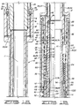
- valve of the present invention is shown as a safety valve for a jack-up rig, generally designated by the numeral 10.
- a central opening 11 is defined longitudinally through valve 10.
- the ball valve mechanism described in more detail herein may be incorporated in virtually any ball valve application.
- the device is particularly well adapted for use in situations where the ball valve is utilized to sever coiled tubing in an emergency situation, such as in subsea testing.
- valve 10 includes an upper body 12 connected to an upper portion 14 of the jack-up rig at threaded connection 16.
- a sealing means, such as O-ring 18 provides sealing engagement therebetween.
- the upper end of upper body 12 has a pair of shoulders 20 and 22. Extending downwardly from shoulder 20 is a passage 23 forming an upper portion of a balance line passageway 24. As seen by the drawings, passage 23 is formed by a plurality of drilled holes with the outer ends thereof plugged. This type of formation of a passage is well known in the art, and therefore a detailed description of each hole and plug will not be provided herein.
- Another passage 25 forming an upper portion of a control line passageway 26 extends downwardly from shoulder 22. Passage 25 opens at lower end 27 of upper body 12 as seen in FIG. 1B.
- a balance line 28 is connected to balance line passageway 24 by a means known in the art, such as tube fitting 30.
- a control line 32 is connected to control line passageway 26 by a tube fitting 34.
- upper body 12 is attached to spring housing 36 at threaded connection 38. Sealing engagement is provided between upper body 12 and spring housing 36 by a sealing means, such as a plurality of O-rings 40, 42 and 44.
- Spring housing 36 defines a passage 46 therein which is in communication with passage 23 and upper body 12 at location 48.
- passage 46 forms a portion of balance line passageway 24. It will be seen that O-rings 42 and 44 seal on opposite sides of location 48 and between upper body 12 and spring housing 36.
- Spring housing 36 also defines another passage 50 therein which is in communication with an unshown passage in upper body 12 at location 52.
- the unshown passage in upper body 12 is similar to passage 23 and is angularly spaced about the vertical axis of valve 10 from both of passages 23 and 25.
- the upper end of the unshown passage may be connected to a chemical injection line.
- the unshown passage and passage 50 form portions of a chemical injection line passageway 53.
- O-rings 40 and 42 provide sealing engagement between spring housing 36 in upper body 12 on opposite sides of location 52.
- the lower end of upper body 12 defines a bore 54 therein with a downwardly facing shoulder 56 at the upper end of the bore.
- An elongated piston 58 has a first outside diameter 60 slidably disposed within bore 54 of upper body 12. Upward movement of piston 58 is limited by contact of upper end 62 thereof with shoulder 56 in spring housing 36.
- a sealing means, such as a pair of O-rings 64 provide sealing engagement between first outside diameter 60 of piston 58 and upper body 12. O-rings 64 seal on opposite sides of a transverse portion 66 of passage 46.
- An upper spring seat 68 is disposed around a second outside diameter 70 of piston 58 and clamped against an annular shoulder 72 by a seat retainer 74.
- Seat retainer 74 is connected to piston 58 by threaded connection 76.
- a sealing means such as a pair of O-rings 78, provide sealing engagement between upper spring seat 68 and piston 58.
- Upper spring seat 68 is thus movable with piston 58 and may be considered a portion thereof. Upper spring seat 68 is slidably received within a bore 80 in spring housing 36, and a sealing means, such as a pair of O-rings 82, provides sealing engagement between upper spring seat 68 and spring housing 36.
- valve housing 84 the lower end of spring housing 36 is attached to valve housing 84 at threaded connection 86.
- a sealing means such as a plurality of O-rings 88, 90 and 92, provide sealing engagement between spring housing 36 and valve housing 84.
- a seat ring 94 is slidably disposed around piston 58 and adapted for substantially constant engagement with upper end 96 of valve housing 84.
- a lower spring seat 98 is positioned on seat ring 94 and located thereby.
- a biasing means, such as a spring 100 is disposed between upper spring seat 68 and lower spring seat 98, and it will thus be seen that upper spring seat 68 and piston 58 are biased upwardly by spring 100.
- This upward position is shown on the left side of FIGS. 1B and 1C, and as will be further described herein, corresponds to a closed position of valve 10.
- a piston chamber 102 is defined annularly between piston 58 and spring housing 36 and above upper spring seat 68.
- a spring chamber 104 is similarly defined below upper spring seat 68.
- spring chamber 104 is filled with nitrogen.
- the nitrogen acts as a gas "spring" so that, as upper spring seat 68 and piston 58 are moved downwardly to reduce the volume of spring chamber 104, the nitrogen will be compressed, thereby increasing the pressure thereof.
- This increased pressure acts upwardly on upper spring seat 68 to bias the upper spring seat and piston 58 upwardly.
- there is an upward biasing means which includes spring 100 and the nitrogen in spring chamber 104.
- Valve housing 84 defines a passage 106 therein which is in communication with the lower end of passage 46 in spring housing 36 at location 108. It will thus be seen that passage 106 also forms a portion of balance line passageway 24. O-rings 88 and 90 seal above and below, respectively, at location 68.
- a floating poppet valve 110 is disposed between spring chamber 104 and balance line passageway 24.
- relief valve 110 When in the position shown in FIG. 1B, relief valve 110 is spaced above a balance port 111 formed in valve housing 84.
- balance port 111 is in communication with passage 106 and thus may be considered a portion of balance line passageway 24.
- second outside diameter 122 of piston 58 is slightly smaller than first bore 124 in valve housing 84, that balance port 111 is in communication with spring chamber 104.
- spring chamber 104 is in communication with balance line passageway 24.
- Fluid can be pumped through balance line passageway 23 so that the fluid enters spring chamber 104 through balance port 111.
- the pressure in spring chamber 104 can be increased to provide an additional upward force on upper spring seat 68 to force the upper spring seat and piston 58 upwardly.
- this provides additional force in severing coiled tubing extending through valve 10.
- Valve housing 84 also defines another passage 112 therein which is in communication with passage 50 in spring housing 36 at location 114, and thus forms a portion of chemical injection line passageway 53. O-rings 90 and 92 seal on opposite sides of location 114.
- piston 58 has a second outside diameter 122 which is slidably disposed within a first bore 124 in spring housing 84.
- a sealing means such as O-ring 126, provides sealing engagement between piston 58 and valve housing 84.
- valve housing 84 The lower end of valve housing 84 is attached to a lower adapter 128 at threaded connection 130.
- a sealing means such as O-ring 132, provides sealing engagement between valve housing 84 and lower adapter 128.
- Lower adapter 128 has a bore 134 therethrough which is in communication with central opening 11 when valve 10 is open.
- Valve housing 84 defines a second bore 136 which is somewhat larger than first bore 124 and an even larger third bore 138.
- a downwardly facing annular shoulder 140 is defined between second and third bores 136 and 138, and this shoulder generally faces upper end 142 of lower adapter 128.
- a ball valve assembly 150 is disposed within valve housing 84 and generally located above lower adapter 128.
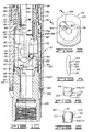
- Valve assembly 150 is an improved ball valve mechanism and is shown in an exploded view in FIG. 2.
- Lower adapter 128 is also seen in FIG. 2.
- Valve assembly 150 comprises a first or upper seat 152, a ball 154 with a ball port 155 defined therethrough, first and second control arms 156 and 158, first and second control frames 160 and 162, alignment sleeves 163, first and second control pins 164 and 166, and a second or lower seat 168 which is disposed in lower adapter 128.
- the lower end of piston 58 is attached to upper seat 152 at threaded connection 170, and thus the upper seat is moveable with the piston.
- a sealing means, such as O-ring 172 provides sealing engagement therebetween.
- Upper seat 152 has a first outside diameter 174 adapted for sliding within second bore 136 of valve housing 84.
- each lug 178 On each side of upper seat 152 is a flat surface 176 with a pair of lugs 178 extending radially outwardly therefrom. Each lug 178 has an upper surface or shoulder 180 which faces upwardly. A recess 182 is defined above flat surface 176 and lugs 178.
- First and second control arms 156 are generally T-shaped having vertical portions 184 and 186 with cross members 188 and 190 extending therefrom, respectively.
- a pivot pin 192 extends inwardly from vertical portion 184 of control arm 156, and similarly, a pivot pin 194 extends inwardly from vertical portion 186 of control arm 158.
- Cross members 188 and 184 of control arms 156 and 158, respectively, are positioned in recesses 182 and are adapted to bear on shoulders 180 of lugs 178 on upper seat 152, with vertical portions 184 and 186 extending through the gap between adjacent lugs 178.
- the inner surface of each of vertical portions 184 and 186 substantially flatly contacts the corresponding flat surface 178.
- ball 154 has a pair of flats 200 parallel to the axis of valve port 155. Only one of flats 200 is visible in the drawings. Pivot bore 196 extends between flats 200, and it will be seen that vertical portions 184 and 186 of control arms 156 and 158 are partially in substantially flat contact with flats 200.
- Each of flats 200 has a slot 202 therein which extends partially into curved outer surface 203 of ball 154.
- Each slot 202 has a flat bottom surface 204 with a pair of opposite, outwardly beveled sides or bearing surfaces 206 extending therefrom.
- slot 202 preferably has an equilateral, trapezoidal cross section.
- the invention is not intended to be limited to a trapezoidal shape, and other configurations may also be used.
- the slots and control pins could have generally rectangular or other shape cross-sections.
- Control pin 164 is basically a mirror image of control pin 166, and the differences in control pin 164 and from control pin 166 are shown in phantom lines in FIG. 6.
- Control pin 166 has a first end having a substantially trapezoidal profile as seen in FIG. 5 with a flat side 210 and a pair of beveled sides or bearing surfaces 212. As seen in FIG. 6, first end 208 of control pin 166 also has an angled side or notch 214 which extends from one beveled side 212. The only difference between control pins 164 and 166 is that control pin 164 has an angled side or notch 214' extending from the other beveled side 212, as seen in the phantom lines of FIG. 6.
- control pins 164 and 166 also have a second, substantially cylindrical end 216.
- first end 208 of each of control pins 204 is adapted to slidingly fit within corresponding slots 202 in ball 154.
- beveled sides 212 of control pins 164 and 166 face the corresponding beveled sides 206 of each slot 202
- flat sides 210 of the control pins face bottom surface 204 of slots 202.
- facing beveled sides 206 and 212 provide a relatively large area of flat bearing contact between the control pins and ball 154.
- Each of second ends 216 of control pins 164 and 166 fits within an opening 218 in the corresponding control frames 160 and 162.
- Openings 218 are spaced in the same direction from a longitudinal axis of control frames 160 and 162.
- a bushing 220 is disposed in each opening 218.
- Second end 216 of control pins 164 and 166 are adapted to fit closely within bushings 220 so that the control pins are rotatable with respect thereto.
- lower seat 168 has a pair of opposite, upwardly extending lugs 228 thereon.
- Lugs 228 extend into notches 230 defined in the lower ends of control frames 160 and 162.
- Lower ends 232 of control frames 160 and 162 generally abut upper face 234 of lower seat 168. See also FIG. 1C.
- the interaction of lugs 228 with notches 230 helps prevent movement of control frames 160 and 162 within valve housing 84 which is particularly important when valve assembly 150 is closed to sever coiled tubing extending therethrough.
- a pair of alignment sleeves 236 are disposed within valve housing 84 adjacent to third bore 138 thereof.
- Each alignment sleeve 236 has opposite longitudinally extending shoulders 238 and 240 thereon.
- Each of shoulder 238 of alignment sleeves 236 is adapted to fit adjacent to one of longitudinal edges 242 of control frame 162, and shoulders 240 on the alignment sleeves are adapted to fit adjacent to longitudinal edges 244 of control frame 160.
- Each alignment sleeve 236 also has a pair of longitudinal faces 246 and 248 thereon. Faces 246 and 248 extend between control frames 160 and 162. Each face 246 abuts control frame 162, and each face 248 abuts control frame 160. It will thus be seen by those skilled in the art that alignment sleeves 236 and control frames 160 and 162 nest together so that, along with the interaction of lugs 228 on lower seat 168 with notches 230 in the control frames, any significant movement of the control frames and alignment sleeves is prevented. In other words, control frames 160 and 162, alignment sleeves 160, and lower seat 168 form a relatively rigid structure when placed together. This lack of movement is particularly important to prevent rotation or twisting of the parts within valve assembly 150 as the valve assembly is closed to sever a piece of coiled tubing extending therethrough.
- Each of alignment sleeves 236 also defines an elongated slot 250 therethrough. These slots allow additional lateral room for the coiled tubing to bend as it is severed by the valve. That is, the coiled tubing can move all the way out so that it contacts third bore 138 in valve housing 84. In this way, the valve of the present invention accommodates the coiled tubing string and reduces the plastic deformation of the tubing string as it is cut by the closing ball valve in a manner somewhat similar to that shown in U. S. Patent No. 5,284,209 to Godfrey, assigned to the assignee of the present invention. A copy of the Godfrey patent is incorporated herein by reference.
- valve housing 84 has a downwardly facing shoulder 222 thereon, and passage 114 ends at this shoulder.
- a tube fitting 224 is used to connect passage 114, and thus chemical injection line passageway 53 with a downwardly extending tube 226.
- Tube 226 is connected to lower portions of the jack-up rig in a manner known in the art so that chemicals may be injected through chemical injection line passageway 53 and tube 226 to any desired location below valve 10.
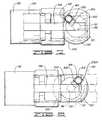
- valve 10 is shown in an open position in which valve port 155 is aligned with, and provides communication between, central opening 11 and bore 134 in lower adapter 128.
- Curvilinear outer surface 203 of ball 154 is in substanitally sealing contact with seating surface 198 in upper seat 152 and with lower seat 168 when in this position.
- valve 10 is shown in a closed position in which valve port 155 is perpendicular to central opening 11 and bore 134, and curvilinear outer surface 203 of ball 154 is sealingly engaged with seating surface 198 in upper seat 152.
- control frames 160 and 162 are preferably stationary and do not move significantly with respect to valve housing 84 or lower adapter 128.
- valve assembly 150 of valve 10 is in the closed position in which spring 100 and the nitrogen charge in spring chamber 104 biases upper spring seat 68 and piston 58 upwardly so that upper end 62 of the piston contacts shoulder 56 in upper body 12, as seen in FIG. 1B.
- This upward position of piston 158 corresponding to an upward position of upper seat 152 since the piston is attached to the upper seat.
- control arms 156 and 158 maintain ball 154 in contact with upper seat 152, and thus ball 154 is also in an upper position.
- control pin 164 is positioned radially outwardly in slot 202 and spaced away from pivot hole 196 in ball 154.
- Control pin 166 is similarly positioned.
- control line passageway 26 is pressurized which also means that piston chamber 102 is pressurized.
- the pressure in piston chamber 102 exerts a downward force on upper spring seat 68, thereby forcing the upper spring seat and the piston 58 downwardly to compress spring 100.
- upper seat 152, control arms 156 and 158, and ball 154 of ball valve assembly 150 also being moved downwardly.
- the interaction of control pins 164 and 166 with slots 202 in ball 154 cause the ball to be rotated as this downward movement occurs. When viewed in FIGS. 7 and 8, this rotation of ball 154 is counterclockwise. As the ball rotates through approximately 45°, control pins 164 and 166 slide radially inwardly within the corresponding slots 202 toward pivot hole 196.
- control pins 164 and 166 slide radially outwardly in the corresponding slots 202 away from pivot hole 196 until the control pins are in the position shown for control pin 164 in FIG. 7.
- the ball pivots on pivot pins 192 and 194 of control arms 156 and 158, respectively.
- any liquid from balance line passageway 23 which may have entered the lower portion of spring chamber 104 will be forced outwardly through balance port 111 by the nitrogen in the spring chamber. Further downward movement results in sufficient compression of the nitrogen that the pressure is increased sufficiently to move poppet valve 110 downwardly to cover balance port 111. This prevents escape of the nitrogen from spring chamber 104.
- the nitrogen acts as a gas spring in addition to mechanical spring 100 as upper spring seat 68 and piston 58 are moved downwardly. In other words, the mechanical force of spring 100 biases upper spring seat 68 and piston 58 upwardly, but the compressed nitrogen in spring chamber 104 also provides an upward biasing force.
- valve 10 Once valve 10 is opened, various downhole tools may be lowered on coiled tubing or a wireline through aligned central opening 11, ball port 155 and bore 134 in a manner known in the art.
- control pins 164 and 166 have beveled sides 212 adapted for flatly contacting the facing beveled sides 206, depending upon the direction of load, in slots 202 of ball 154, it will be seen that a much greater area of contact is provided than in previously known balls in which a round pin simply slides along one side of a slot. This allows a greater load to be transmitted from the control pins to ball 154 to provide the shearing load necessary to shear relatively large diameters of coiled tubing which extend through the open valve.
- valve assembly 150 Additional bearing load is provided for first and second control arms 156 and 158 by the increased bearing area on lugs 178 and in recess 182 on upper seat 152. As previously described, additional strength is provided in valve assembly 150 by the interlocking arrangement of alignment sleeves 236, control frames 160 and 162, and lugs 228 on lower seat 168. Thus, as valve assembly 150 is closed to sever coiled tubing extending therethrough, sufficient strength is provided to the components and relative movement therebetween is prevented so that damage to the components or binding thereof is substantially eliminated.
- valve 10 can sever relatively large diameters of coiled tubing extending therethrough and still provide long life for the components in valve assembly 150.
Landscapes
- Life Sciences & Earth Sciences (AREA)
- Engineering & Computer Science (AREA)
- Geology (AREA)
- Mining & Mineral Resources (AREA)
- Physics & Mathematics (AREA)
- Environmental & Geological Engineering (AREA)
- Fluid Mechanics (AREA)
- General Life Sciences & Earth Sciences (AREA)
- Geochemistry & Mineralogy (AREA)
- Taps Or Cocks (AREA)
Applications Claiming Priority (2)
| Application Number | Priority Date | Filing Date | Title |
|---|---|---|---|
| US236787 | 1994-04-29 | ||
| US08/236,787 US5551665A (en) | 1994-04-29 | 1994-04-29 | Ball valve with coiled tubing cutting ability |
Publications (3)
| Publication Number | Publication Date |
|---|---|
| EP0679796A2 true EP0679796A2 (de) | 1995-11-02 |
| EP0679796A3 EP0679796A3 (de) | 1997-01-02 |
| EP0679796B1 EP0679796B1 (de) | 1999-08-04 |
Family
ID=22890966
Family Applications (1)
| Application Number | Title | Priority Date | Filing Date |
|---|---|---|---|
| EP95302877A Expired - Lifetime EP0679796B1 (de) | 1994-04-29 | 1995-04-27 | Kugelventil |
Country Status (3)
| Country | Link |
|---|---|
| US (1) | US5551665A (de) |
| EP (1) | EP0679796B1 (de) |
| DE (1) | DE69511150D1 (de) |
Cited By (5)
| Publication number | Priority date | Publication date | Assignee | Title |
|---|---|---|---|---|
| WO2000015943A1 (en) * | 1998-09-15 | 2000-03-23 | Expro North Sea Limited | Improved ball valve |
| US6085845A (en) * | 1996-01-24 | 2000-07-11 | Schlumberger Technology Corporation | Surface controlled formation isolation valve adapted for deployment of a desired length of a tool string in a wellbore |
| GB2369383A (en) * | 2000-10-23 | 2002-05-29 | Vetco Gray Inc Abb | Ball valve for fluid flow control and for cutting a wireline |
| CN102080512A (zh) * | 2011-01-05 | 2011-06-01 | 深圳市远东石油钻采工程有限公司 | 一种深水弃井切割装置中的多位单向旁通接结构 |
| US8925894B2 (en) | 2012-02-17 | 2015-01-06 | Vetco Gray Inc. | Ball valve enclosure and drive mechanism |
Families Citing this family (21)
| Publication number | Priority date | Publication date | Assignee | Title |
|---|---|---|---|---|
| US5782304A (en) * | 1996-11-26 | 1998-07-21 | Garcia-Soule; Virgilio | Normally closed retainer valve with fail-safe pump through capability |
| US6152229A (en) * | 1998-08-24 | 2000-11-28 | Abb Vetco Gray Inc. | Subsea dual in-line ball valves |
| US6834721B2 (en) | 2002-01-14 | 2004-12-28 | Halliburton Energy Services, Inc. | System for disconnecting coiled tubing |
| US6698712B2 (en) | 2002-05-02 | 2004-03-02 | Dril-Quip, Inc. | Ball valve assembly |
| US7195225B1 (en) | 2003-10-30 | 2007-03-27 | Dril-Quip, Inc. | Rotary valve assembly |
| US8662183B1 (en) * | 2011-02-12 | 2014-03-04 | Louis P. Vickio, Jr. | Blow out preventer |
| US8727315B2 (en) | 2011-05-27 | 2014-05-20 | Halliburton Energy Services, Inc. | Ball valve |
| US9243467B2 (en) * | 2011-07-06 | 2016-01-26 | Halliburton Energy Services, Inc. | Safety system for oil and gas drilling operations |
| GB2493180A (en) * | 2011-07-27 | 2013-01-30 | Expro North Sea Ltd | Valve housing arrangement |
| EP2568109B1 (de) * | 2011-09-06 | 2015-02-25 | Vetco Gray Inc. | Kugelventilanordnung |
| GB201116966D0 (en) * | 2011-10-03 | 2011-11-16 | Nat Oilwell Varco Uk Ltd | Valve |
| CA2869762A1 (en) * | 2012-05-18 | 2013-11-21 | Halliburton Energy Services, Inc. | Elongated trunnion for high pressure ball valves |
| US9410391B2 (en) * | 2012-10-25 | 2016-08-09 | Schlumberger Technology Corporation | Valve system |
| GB201317799D0 (en) * | 2013-10-08 | 2013-11-20 | Expro North Sea Ltd | Valve Assembly |
| US10006262B2 (en) | 2014-02-21 | 2018-06-26 | Weatherford Technology Holdings, Llc | Continuous flow system for drilling oil and gas wells |
| GB2527768B (en) * | 2014-06-30 | 2017-10-25 | Interventek Subsea Eng Ltd | Test tree and actuator |
| US10550667B2 (en) * | 2017-10-23 | 2020-02-04 | CNPC USA Corp. | Isolation valve assembly |
| NO343784B1 (en) * | 2017-10-27 | 2019-06-03 | Moonshine Solutions As | An improved drill string safety valve device |
| US12055003B2 (en) * | 2019-04-29 | 2024-08-06 | Halliburton Energy Services, Inc. | Advanced loading method for ball rotation cutting and method of use therefor |
| CN114622859B (zh) * | 2022-04-08 | 2023-12-26 | 北京中天必捷能源技术有限责任公司 | 新型的切割组合球及切割工艺 |
| US11965394B1 (en) * | 2023-08-25 | 2024-04-23 | Halliburton Energy Services, Inc. | Subsea test tree fast ball actuation with low pressure pump through capability |
Family Cites Families (17)
| Publication number | Priority date | Publication date | Assignee | Title |
|---|---|---|---|---|
| US3007669A (en) * | 1956-09-13 | 1961-11-07 | Otis Eng Co | Valve |
| US3411576A (en) * | 1965-07-02 | 1968-11-19 | Otis Eng Co | Well tools |
| USRE27464E (en) * | 1969-11-10 | 1972-08-22 | Well tools | |
| US3826462A (en) * | 1972-11-01 | 1974-07-30 | Otis Eng Corp | Large bore rotary safety valves for wells |
| US3886967A (en) * | 1973-09-24 | 1975-06-03 | Fmc Corp | Downhole safety ball valve |
| US4044835A (en) * | 1975-05-23 | 1977-08-30 | Hydril Company | Subsurface well apparatus having improved operator means and method for using same |
| US4009753A (en) * | 1976-03-22 | 1977-03-01 | Schlumberger Technology Corporation | Subsea master valve apparatus |
| CA1087519A (en) * | 1977-04-25 | 1980-10-14 | Michael B. Calhoun | Well tools |
| US4287954A (en) * | 1979-08-20 | 1981-09-08 | Hydril Company | Subsurface safety valve |
| US4494609A (en) * | 1981-04-29 | 1985-01-22 | Otis Engineering Corporation | Test tree |
| US4421171A (en) * | 1981-05-21 | 1983-12-20 | Baker International Corporation | Valve operable under oppositely directed pressure differentials |
| US4522370A (en) * | 1982-10-27 | 1985-06-11 | Otis Engineering Corporation | Valve |
| FR2557664B1 (fr) * | 1983-12-28 | 1986-08-29 | Flopetrol | Vanne de securite, en particulier pour fermer un puits de petrole |
| US5050839A (en) * | 1989-02-15 | 1991-09-24 | Otis Engineering Corporation | Valve |
| US4967844A (en) * | 1989-03-30 | 1990-11-06 | Elder Oil Tools | Selectively operable ball valve and production packer system |
| US5284209A (en) * | 1992-08-19 | 1994-02-08 | Halliburton Company | Coiled tubing cutting modification |
| US5338001A (en) * | 1992-11-17 | 1994-08-16 | Halliburton Company | Valve apparatus |
-
1994
- 1994-04-29 US US08/236,787 patent/US5551665A/en not_active Expired - Lifetime
-
1995
- 1995-04-27 DE DE69511150T patent/DE69511150D1/de not_active Expired - Lifetime
- 1995-04-27 EP EP95302877A patent/EP0679796B1/de not_active Expired - Lifetime
Cited By (9)
| Publication number | Priority date | Publication date | Assignee | Title |
|---|---|---|---|---|
| US6085845A (en) * | 1996-01-24 | 2000-07-11 | Schlumberger Technology Corporation | Surface controlled formation isolation valve adapted for deployment of a desired length of a tool string in a wellbore |
| WO2000015943A1 (en) * | 1998-09-15 | 2000-03-23 | Expro North Sea Limited | Improved ball valve |
| US6708946B1 (en) | 1998-09-15 | 2004-03-23 | Expro North Sea Limited | Ball valve |
| GB2369383A (en) * | 2000-10-23 | 2002-05-29 | Vetco Gray Inc Abb | Ball valve for fluid flow control and for cutting a wireline |
| US6668933B2 (en) | 2000-10-23 | 2003-12-30 | Abb Vetco Gray Inc. | Ball valve seat and support |
| GB2369383B (en) * | 2000-10-23 | 2004-12-29 | Vetco Gray Inc Abb | Ball valve seat and support |
| CN102080512A (zh) * | 2011-01-05 | 2011-06-01 | 深圳市远东石油钻采工程有限公司 | 一种深水弃井切割装置中的多位单向旁通接结构 |
| CN102080512B (zh) * | 2011-01-05 | 2013-03-20 | 深圳市远东石油钻采工程有限公司 | 一种深水弃井切割装置中的多位单向旁通接结构 |
| US8925894B2 (en) | 2012-02-17 | 2015-01-06 | Vetco Gray Inc. | Ball valve enclosure and drive mechanism |
Also Published As
| Publication number | Publication date |
|---|---|
| EP0679796B1 (de) | 1999-08-04 |
| DE69511150D1 (de) | 1999-09-09 |
| US5551665A (en) | 1996-09-03 |
| EP0679796A3 (de) | 1997-01-02 |
Similar Documents
| Publication | Publication Date | Title |
|---|---|---|
| EP0679796B1 (de) | Kugelventil | |
| US5284209A (en) | Coiled tubing cutting modification | |
| US6227299B1 (en) | Flapper valve with biasing flapper closure assembly | |
| EP1000220B1 (de) | Schliessvorrichtung für ein bypass-ventil | |
| US5575336A (en) | Safety valve for horizontal tree | |
| US4714116A (en) | Downhole safety valve operable by differential pressure | |
| EP0416719B1 (de) | Schiebeventil mit Scherwirkung | |
| US10584561B2 (en) | Dirty fluid pressure regulator and control valve | |
| US6125930A (en) | Downhole valve | |
| US4467867A (en) | Subterranean well safety valve with reference pressure chamber | |
| EP2489827B1 (de) | Selbstverstärkendes nicht elastomeres elastisches Siegel für ein Rückschlagventil | |
| US4621695A (en) | Balance line hydraulically operated well safety valve | |
| US4943031A (en) | Blowout preventer | |
| US20030205688A1 (en) | Ball valve assembly | |
| EP0953097A1 (de) | Druckausgeglichenes sicherheitsventil für bohrlöcher | |
| US20110266472A1 (en) | Self piloted check valve | |
| CA2160817C (en) | Subsurface safety valve | |
| WO1999020869A2 (en) | Equalizing subsurface safety valve with injection system | |
| US4641682A (en) | Valve with rotary valve head | |
| US6607037B2 (en) | Sand control seal for subsurface safety valve | |
| US3713485A (en) | Petroleum well safety valve | |
| US3726341A (en) | Petroleum well tubing safety valve | |
| US4071088A (en) | Retrievable safety valve | |
| RU2107152C1 (ru) | Скважинный клапан-отсекатель | |
| US5975212A (en) | Surface controlled subsurface safety valve downstop seal |
Legal Events
| Date | Code | Title | Description |
|---|---|---|---|
| PUAI | Public reference made under article 153(3) epc to a published international application that has entered the european phase |
Free format text: ORIGINAL CODE: 0009012 |
|
| AK | Designated contracting states |
Kind code of ref document: A2 Designated state(s): DE FR GB NL |
|
| PUAL | Search report despatched |
Free format text: ORIGINAL CODE: 0009013 |
|
| AK | Designated contracting states |
Kind code of ref document: A3 Designated state(s): DE FR GB NL |
|
| 17P | Request for examination filed |
Effective date: 19970211 |
|
| 17Q | First examination report despatched |
Effective date: 19971027 |
|
| GRAG | Despatch of communication of intention to grant |
Free format text: ORIGINAL CODE: EPIDOS AGRA |
|
| GRAG | Despatch of communication of intention to grant |
Free format text: ORIGINAL CODE: EPIDOS AGRA |
|
| GRAH | Despatch of communication of intention to grant a patent |
Free format text: ORIGINAL CODE: EPIDOS IGRA |
|
| GRAH | Despatch of communication of intention to grant a patent |
Free format text: ORIGINAL CODE: EPIDOS IGRA |
|
| RAP1 | Party data changed (applicant data changed or rights of an application transferred) |
Owner name: HALLIBURTON ENERGY SERVICES, INC. |
|
| GRAA | (expected) grant |
Free format text: ORIGINAL CODE: 0009210 |
|
| AK | Designated contracting states |
Kind code of ref document: B1 Designated state(s): DE FR GB NL |
|
| PG25 | Lapsed in a contracting state [announced via postgrant information from national office to epo] |
Ref country code: FR Free format text: THE PATENT HAS BEEN ANNULLED BY A DECISION OF A NATIONAL AUTHORITY Effective date: 19990804 |
|
| REF | Corresponds to: |
Ref document number: 69511150 Country of ref document: DE Date of ref document: 19990909 |
|
| ET | Fr: translation filed | ||
| PG25 | Lapsed in a contracting state [announced via postgrant information from national office to epo] |
Ref country code: DE Free format text: LAPSE BECAUSE OF FAILURE TO SUBMIT A TRANSLATION OF THE DESCRIPTION OR TO PAY THE FEE WITHIN THE PRESCRIBED TIME-LIMIT Effective date: 19991105 |
|
| PLBE | No opposition filed within time limit |
Free format text: ORIGINAL CODE: 0009261 |
|
| STAA | Information on the status of an ep patent application or granted ep patent |
Free format text: STATUS: NO OPPOSITION FILED WITHIN TIME LIMIT |
|
| 26N | No opposition filed | ||
| REG | Reference to a national code |
Ref country code: GB Ref legal event code: IF02 |
|
| REG | Reference to a national code |
Ref country code: FR Ref legal event code: ST |
|
| PGFP | Annual fee paid to national office [announced via postgrant information from national office to epo] |
Ref country code: NL Payment date: 20040406 Year of fee payment: 10 |
|
| PG25 | Lapsed in a contracting state [announced via postgrant information from national office to epo] |
Ref country code: NL Free format text: LAPSE BECAUSE OF NON-PAYMENT OF DUE FEES Effective date: 20051101 |
|
| NLV4 | Nl: lapsed or anulled due to non-payment of the annual fee |
Effective date: 20051101 |
|
| REG | Reference to a national code |
Ref country code: GB Ref legal event code: 732E |
|
| PGFP | Annual fee paid to national office [announced via postgrant information from national office to epo] |
Ref country code: GB Payment date: 20090422 Year of fee payment: 15 |
|
| GBPC | Gb: european patent ceased through non-payment of renewal fee |
Effective date: 20100427 |
|
| PG25 | Lapsed in a contracting state [announced via postgrant information from national office to epo] |
Ref country code: GB Free format text: LAPSE BECAUSE OF NON-PAYMENT OF DUE FEES Effective date: 20100427 |