EP0679573B1 - Vehicle seat - Google Patents
Vehicle seat Download PDFInfo
- Publication number
- EP0679573B1 EP0679573B1 EP95302706A EP95302706A EP0679573B1 EP 0679573 B1 EP0679573 B1 EP 0679573B1 EP 95302706 A EP95302706 A EP 95302706A EP 95302706 A EP95302706 A EP 95302706A EP 0679573 B1 EP0679573 B1 EP 0679573B1
- Authority
- EP
- European Patent Office
- Prior art keywords
- seat
- support
- frame
- seat frame
- poles
- Prior art date
- Legal status (The legal status is an assumption and is not a legal conclusion. Google has not performed a legal analysis and makes no representation as to the accuracy of the status listed.)
- Expired - Lifetime
Links
- 238000006073 displacement reaction Methods 0.000 claims abstract description 9
- 238000007373 indentation Methods 0.000 claims abstract description 6
- 229910052751 metal Inorganic materials 0.000 description 7
- 239000002184 metal Substances 0.000 description 7
- 230000006378 damage Effects 0.000 description 3
- 229910000838 Al alloy Inorganic materials 0.000 description 2
- 208000027418 Wounds and injury Diseases 0.000 description 2
- 230000008878 coupling Effects 0.000 description 2
- 238000010168 coupling process Methods 0.000 description 2
- 238000005859 coupling reaction Methods 0.000 description 2
- 230000000694 effects Effects 0.000 description 2
- 208000014674 injury Diseases 0.000 description 2
- 230000003993 interaction Effects 0.000 description 2
- 230000004044 response Effects 0.000 description 2
- 230000002238 attenuated effect Effects 0.000 description 1
- 238000005452 bending Methods 0.000 description 1
- 230000008901 benefit Effects 0.000 description 1
- 238000006243 chemical reaction Methods 0.000 description 1
- 238000010276 construction Methods 0.000 description 1
- 239000003562 lightweight material Substances 0.000 description 1
- 238000012423 maintenance Methods 0.000 description 1
- 239000000463 material Substances 0.000 description 1
- 230000007246 mechanism Effects 0.000 description 1
- 230000021715 photosynthesis, light harvesting Effects 0.000 description 1
- 230000009467 reduction Effects 0.000 description 1
- 238000004088 simulation Methods 0.000 description 1
Images




Classifications
-
- B—PERFORMING OPERATIONS; TRANSPORTING
- B64—AIRCRAFT; AVIATION; COSMONAUTICS
- B64D—EQUIPMENT FOR FITTING IN OR TO AIRCRAFT; FLIGHT SUITS; PARACHUTES; ARRANGEMENT OR MOUNTING OF POWER PLANTS OR PROPULSION TRANSMISSIONS IN AIRCRAFT
- B64D25/00—Emergency apparatus or devices, not otherwise provided for
- B64D25/02—Supports or holding means for living bodies
- B64D25/04—Seat modifications
-
- Y—GENERAL TAGGING OF NEW TECHNOLOGICAL DEVELOPMENTS; GENERAL TAGGING OF CROSS-SECTIONAL TECHNOLOGIES SPANNING OVER SEVERAL SECTIONS OF THE IPC; TECHNICAL SUBJECTS COVERED BY FORMER USPC CROSS-REFERENCE ART COLLECTIONS [XRACs] AND DIGESTS
- Y10—TECHNICAL SUBJECTS COVERED BY FORMER USPC
- Y10S—TECHNICAL SUBJECTS COVERED BY FORMER USPC CROSS-REFERENCE ART COLLECTIONS [XRACs] AND DIGESTS
- Y10S248/00—Supports
- Y10S248/90—Movable or disengageable on impact or overload
Definitions
- the present invention relates to impact attenuation apparatus in general and, more particularly, to energy attenuating aircraft seats which meet aircraft safety requirements.
- the aircraft may be expected to dissipate up to approximately 50% of the crash energy through the landing gear while an approximately additional 15% will be dissipated through the controlled crash of the fuselage structure.
- the remaining crash energy is, inevitably, absorbed within the aircraft, partly by the occupants and partly by internal elements of the aircraft.
- reduction of the impact on the occupants can be achieved only through energy dissipation within the internal aircraft elements, such as the seats.
- U.S. Patent No. 4,523,730 to Martin describes an energy absorbing seat arrangement, particularly for a helicopter, in which a seat pan is carried by a frame slidably mounted on parallel upwardly extending pillars secured to the helicopter.
- a seat pan is carried by a frame slidably mounted on parallel upwardly extending pillars secured to the helicopter.
- metal rods fixed to the pillars which extend through drawing dies fixed to the seat frame.
- the rods and dies are replaced by a mandrel and a deformable metal tube, respectively. The mandrel extends through the tube.
- the seat and seat frame In the event of a crash in which rapid downward movement of the helicopter and the pillars is halted suddenly, the seat and seat frame continue to move downwardly, sliding along the pillars, while drawing the rods through the dies, or the mandrel through the tube, to dissipate the kinetic energy of the seat and its occupant relatively gradually.
- U.S. Patent 4,997,233 discloses a light weight seat for an aircraft having energy attenuation apparatus.
- the attenuation apparatus described in this patent reduces the impact acting on the seat in a preselected direction by converting part of the impact energy into controlled motion of a support element of the seat toward the preselected direction.
- Such motion occurs only when the impact force exceeds a preselected threshold, typical of crashing, in which case the impact energy resulting from the excessive force is absorbed through plastic deformation of an element designed for that purpose which impedes the motion of the support element.
- the light weight of this seat is partly due to the construction of the seat such that the energy attenuation apparatus is part of the back support apparatus.
- Aircraft passenger seats are generally slidably mounted on parallel rails which allow convenient adjustment of the position of the seat along an axis parallel to the rails.
- the seat is generally mounted on at least four, spaced apart, mounting locations, two on each rail.
- Dislocation of a rail in response to floor deformation resulting from a crash situation includes a "roll” component, defined as the angle of rotation of a rail about its own axis, and a “pitch” component, defined as the angular rotation of the rail about an axis perpendicular to the rail.
- US-A-3985388 discloses a vehicle seat which absorbs energy exerted on this seat during impact.
- This vehicle seat comprises a seat frame having two generally vertical segments and also includes a support apparatus having one generally vertical pole.
- a coupler is fixedly mounted on the pole of the support apparatus and has a deformation member.
- FR-A-2510512 discloses a vehicle seat for absorbing energy exerted on the seat during impact.
- the seat has a seat frame and support apparatus including a generally vertical pole.
- a coupler is fixedly mounted to the seat frame and preferentially mounted to this pole, the coupler having a deformation member.
- a vehicle seat for absorbing energy exerted on the seat during impact comprising:
- the at least one deformation member deforms said segment of the seat frame when the impact acting on said seat frame exceeds a preselected threshold.
- a vehicle seat for absorbing energy exerted on the seat during impact comprising:
- the back tilt adjustment apparatus operates independently of other seat adjustment apparatus and/or energy attenuation apparatus included in the seat.
- An embodiment of the invention comprises a seat pan frame
- Another embodiment of the present invention comprises a rigid seat pan frame
- the ends of the support sheet tend to move inwardly from the rigid frame due to high mechanical tensions in the sheet.
- the strength of the support sheet and the number and type of pins used can be chosen such that, in response to high tensions, the pins tear the sheet and/or the strap in a controlled manner, thereby attenuating some of the impact exerted on the seat.
- FIGs. 1 and 2 are respective rear and side view illustrations of a vehicle seat 10, preferably an aircraft pilot seat, constructed and operative in accordance with one preferred embodiment of the present invention, including apparatus for mounting the seat on a floor of a vehicle.
- Seat 10 includes a substantially horizontal pan portion 50, preferably having a pan cushion 52, and a substantially vertical back portion 60, preferably having a back cushion 62.
- Pan portion 50 is preferably pivotally connected to back portion 60, through a corner axis 65, and supported in a desired sitting position by a pair of side cables or chains 67 and a pair of angular adjustors 71.
- An elongated connector 42 described below, is mounted on corner axis 65 and extends rearly therefrom.
- pan portion 50 may be a foldable seat pan assembly which is also tiltably adjustable. This allows for an easy egress and ingress of a user to the seat, especially in vehicles having limited space such as small aircraft. Furthermore, the user may tilt the seat pan at different angles to allow adjustment for an operating mode and for a rest mode.
- Back portion 60 includes a rigid seat frame 32, preferably constructed from a tubular profile of a relatively light weight material, for example an aluminum alloy.
- seat frame 32 is mounted on a pair of substantially parallel primary support poles 26 using couplers 36 and 36a, described below in greater detail.
- the grip of couplers 36a on frame 32 is such that, during normal operating conditions, frame 32 is prevented from sliding along poles 26, as further described below.
- a pair of cushioned arm rests 70 are preferably foldably mounted on both sides of back portion 60, respectively.
- pan portion 50 of seat 10 is preferably provided with a pan cushion support 64 located underneath cushion 52 of pan portion 50.
- back portion 60 of seat 10 includes an inner seat frame 66 adjustably associated with seat frame 32.
- Inner seat frame 66 includes a horizontal support bar 38 substantially parallel to corner axis 65 and to a rear connecting support truss 20.
- a telescopic adjustment member 40 is mounted between bar 38 and elongated connector 42 of axis 65.
- inner frame 66 is pivotally mounted on corner axis 65 such that changes in the length of telescopic adjustment member 40 result in corresponding angular tilt of frame 66 relative to the seat frame 32.
- Adjustment member 40 is preferably a hydraulic telescopic adjustment member having an inner portion 39 and an outer portion 41. By varying the overlap between portions 39 and 41, member 40 is adjusted to a desired length.
- inner frame 66 can be adjusted to a desired tilt with respect to seat frame 32. Since cushion 62 is supported mainly against frame 66, the tilt of cushion 62 corresponds to the tilt of inner frame 66. Thus, in this preferred embodiment of the invention, back cushion 62 can be adjusted to a desired tilt, suitable for the person occupying seat 10, by adjusting the length of member 40.
- Primary support poles 26 are preferably tiltably mounted on a mounting structure 69, which consists of a pair of substantially horizontal, substantially parallel, side support trusses 22, and a rear connecting support truss 20, pivotally mounted across the rear ends of the side support trusses.
- the lower ends of the primary support poles 26 are pivotally mounted on respective primary support sites 24 located approximately at the centers of the upper surfaces of the side support trusses.
- a pair of non-parallel secondary support poles 30 are pivotally coupled to the primary support poles 26, respectively, through respective cuffs 28.
- the lower ends 31 of the secondary poles are jointly attached to a single secondary support site 33 positioned at the approximate center of the upper surface of the connecting support truss 20, and can radially pivot around their attachment sites. It is to be understood that although the primary support poles 26 are pivotally mounted on the primary support sites 24, under normal operating conditions the primary poles do not move due to the support of the secondary support poles 30 and the side trusses 22.
- a pair of rear sliders 16 are fixedly mounted under side trusses 22, near the rear ends thereof, and a pair of front sliders 18 are fixedly mounted under the front ends 23 of the trusses.
- mounting structure 69 of seat 10 is adjustably mounted on two pairs of parallel floor rails, namely rear rails 12 and front rails 14, by virtue of rear sliders 16 and front sliders 18, respectively.
- rail pairs 12 and 14 may be integrated into a single pair of longer parallel rails (not shown).
- sliders 16 are mounted across the rear portions of the integrated rails and sliders 18 are mounted across the front portions of the integrated rails.
- Side trusses 22 are preferably in locking engagement with rails 12 and 14 during normal operation of the vehicle by means of corresponding locking mechanisms 72, each passing through a respective side truss 22, so as to prevent seat 10 from sliding along the rails during motion of the vehicle. This locking may be released when the position of seat 10 on the vehicle floor is to be adjusted. Adjustment of the position of seat 10, backwards and forward, is achieved by sliding of sliders 16 and 18 along rails 12 and 14.
- seat 10 is not directly supported by the four mounting locations, but rather by the three support sites, namely the two primary support sites 24 and the secondary support site 33 on the rear connecting support truss 20.
- the use of three support sites for seat 10, as described above improves the reaction of seat 10 to a typical crash situation, wherein the floor of the vehicle becomes considerably deformed.
- floor deformation results in uneven displacement of rear rails 12, e.g. left rear rail 12 becomes elevated or lowered with respect to right rear rail 12, the corresponding displacement of the secondary support site 33 is considerably less than the displacement of the rear rails, such as by 50%.
- the mounting arrangement of the present invention limits the degree of deformation, such as bending, transferred to the seat.
- This structure of the mounting arrangements also reduces undesired deformation of energy absorbing apparatus mounted on the seat, such as the apparatus described below, thus allowing such apparatus to optimally absorb the energy of the impact and protect the occupant of the seat.
- Fig. 3 is an enlarged cross-section from Fig. 1 of one of primary poles 26 at the location of the respective coupler 36a.
- seat 10 is carried by seat frame 32 which is mounted on parallel primary support poles 26 by virtue of couplers 36 and 36a. Couplers 36 are fixedly attached to frame 32 and slidingly mounted on poles 26, while couplers 36a are fixedly attached to poles 26 and pressure-grip frame 32, as will be explained below. According to a preferred embodiment of the present invention, under normal conditions (i.e when relatively low impacts are acting on seat 10), sliding of frame 32 with respect to poles 26 is prevented due to the grip applied by couplers 36a to frame 32.
- each of the couplers 36a comprises a mounting portion 86, which is fixedly mounted on a preselected location of pole 26, and grip portion 84, which is associated with a preselected location 34 on frame 32.
- Grip portion 84 includes at least one, and preferably several, rigid members 80, which may be rigid metal balls, each associated with at least one, respective, adjustment screw 82.
- Radially inward dents or circumferential grooves 88, each adapted to match a rigid member 80, are preferably formed in location 34 at the sites where rigid members 80 engage the surface of frame 32.
- Rigid members 80 are pressed against locations 34 by adjustment screws 82 which are preferably pre-adjusted so that rigid members 80 are pressed against locations 34 at respective dents 88, applying a predetermined pressure thereat, to thereby provide locking engagement between the frame and grip portions 84 of couplers 36a. It should be noted that screws 82 enable continuous adjustment of the pressure applied by members 80 at locations 34.
- rigid members 80 and dents 88 have preselected fixed positions, preferably chosen in accordance with crash simulation tests performed on seat 10, such that adjustment screws 82 may be replaced with fixed, i.e. unadjustable, supports (not shown in the drawings). This results in lower-cost, lower maintenance, couplers 36a.
- rigid members 80 and screws 82 are replaced by adjustable rigid screws (not shown). The tips of such dual-purpose screws also perform the function of members 80.
- the absorbing apparatus of Fig. 3 is operable to dissipate forces which are activated along an axis.
- large forces are generated in a vertical axis.
- large forces may be generated in a horizontal axis.
- the apparatus of Fig. 3 may be employed to dissipate energy in a horizontal axis by replacing rear and front sliders 16 and 18 with corresponding sliders, preferably in the form of tubes, which include the apparatus of Fig. 3.
- truss 22 may be replaced with a truss which may be a tube including the apparatus of Fig. 3.
- the tube sliders including the apparatus of Fig. 3, and/or the tube-formed truss may dissipate forces in a longitudinal direction.
- couplers 36a may be equally suitable for the purposes of the present invention, such as the embodiment described below with reference to Fig. 4C.
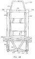
- a vehicle seat 210 shown with an occupant 211 sitting in it, comprises a seat frame 232 which is supported by a horizontal support bar 260.
- the two ends of support bar 260 are connected by respective couplers 236 to a pair of primary support poles 226, as described in more detail below.
- the lower ends of poles 226 are pivotally mounted, about an axis denoted "B", on a pair of primary support sites 224 which are located at the rear ends of a respective pair of side support trusses 222.
- the front ends of the side support trusses 222 are connected to each other by a connecting support truss 220 positioned perpendicularly to the side trusses and pivotally attached to them.
- a pair of non-parallel secondary support poles 230 are jointly attached at their lower ends to a single secondary support site 233 positioned at the approximate center of the connecting support truss 220, and are capable of pivoting around the secondary support site 233.
- seat frame 232 includes a head support portion 240 which is preferably provided with a head cushion (not shown).
- head support portion 240 is provided as a separate element which is mounted on horizontal support bar 260.
- a pan portion 250 supporting a pan cushion 252, is slidingly attached at its rear end to the primary poles 226 and is pivotably supported at its front end, about an axis denoted "A", by the upper ends of the secondary poles 230.
- a pair of diagonal support beams 241 extend from axis "A" to axis "B” to provide the structure with longitudinal stability.
- the vehicle seat 210 is supported by three support sites, namely, the two primary support sites 224 and the single secondary support site 233.
- the secondary site is located anteriorly to the primary sites.
- each of couplers 236 includes a plurality of rigid members 280, preferably rigid metal balls, circumferentially engaging the respective support pole 226 at a respective plurality of inward dents or circular grooves which are preferably formed in the support pole.
- Members 280 are preferably evenly spaced by a separating cage 281 and are urged against the respective dents in poles 226 by virtue of respective pressure rings 282, preferably formed of a rigid metal, which apply predetermined pressures on members 280.
- FIG. 4C shows eight rigid members 280 in each coupler 236, however, any suitable number of members 280 may be used, each being associated with a respective indentation or groove in the respective pole 226.
- couplers 236 are fixedly connected to the respective ends of horizontal support bar 260.
- each ring 282 to members 280 is generally a function of the inward diameter of ring 282 and the number of members 280 used.
- the pressure applied to poles 226 may be adjusted by adjusting the diameters of rings 282 or by changing the number of members 280 used.
- Each of the rings 282 is held in its respective position by a snap ring (not shown), wherein the snap rings hold together the whole coupler 236.
- the pan portion 250 is held stably by the primary and secondary support poles and by the diagonal support beam 241.
- the rear end of the pan portion 250 slides in a generally downward direction along primary support poles 226, pivoting on axis "A”.
- primary support poles 226 are pushed in a generally forward direction, pivoting on axis "B".
- the impact energy is absorbed by the seat rather than by its occupant.
- FIG. 4B A further preferred feature for limiting transfer of pitch deformation from the floor to the seat is illustrated in Fig. 4B.
- On either end of connecting support truss 220 are elongated grooves 290, through each of which protrude a pin 292.
- the connecting support truss 220 pivots around the secondary support site 233, and the pin 292 moves laterally within the groove 290. This effectively lengthens the connecting support truss, so that the deformation of the floor minimally affects the position of the secondary support poles 230 and generally does not effect the structure of seat 210.
- FIG. 5A is a simplified illustration of a vehicle seat 100 constructed and operative in a accordance with an alternative embodiment of the present invention
- Fig. 5B which is a cross section of a front portion 102 of a seat pan 101 of seat 100, taken along section lines III - III.
- seat pan 101 includes a rigid seat pan frame 104, preferably formed of an aluminum alloy having a tubular profile.
- edges 105 of strap 106 are attached to a pan support sheet 110, preferably a metal sheet included in seat pan 101, by means of a series of pins 108 driven through sheet 110 and edges 105 of strap 106.
- Pins 108 may be replaced by rivets bolts and the like.
- the pins may be positioned in parallel along the front and back edges of sheet 110, as shown in Fig. 5A, or, alternatively, along the side edges of the sheet.
- the connection between strap 106 to sheet 110 by virtue of pins 108 withstands any forces acting on sheet 110 and/or strap 106.
- sheet 110 experiences substantial impact perpendicular to sheet 110, which causes tension forces in the direction indicated by arrow 112
- either or both of sheet 110 and strap 106 are torn by pins 108.
- Such tearing generally perpendicular to the direction of the impact force, attenuates the impact experienced by seat 100. It should be appreciated that in addition to some energy dissipated in the tearing of sheet 110 and/or strap 106, the impact is attenuated also through the somewhat controlled motion of seat 100 along the direction of the tearing.
- sheet 110, strap 106 and pins 108 are designed such that tearing of sheet 110 and/or strap 106 will occur only when the impact acting perpendicular to the plane of sheet 110 exceeds a preselected threshold typical of a crash situation. It should be appreciated that although the apparatus of Figs. 5A and 5B is particularly suitable for generally vertical impact attenuation, similar apparatus may be employed at the back of seat 100 to provide generally horizontal impact attenuation.
- any or all of the above mentioned energy attenuation apparatus may be employed in a given vehicle seat, preferably an aircraft pilot seat.
Landscapes
- Business, Economics & Management (AREA)
- Emergency Management (AREA)
- Engineering & Computer Science (AREA)
- Aviation & Aerospace Engineering (AREA)
- Seats For Vehicles (AREA)
- Vehicle Waterproofing, Decoration, And Sanitation Devices (AREA)
Abstract
Description
Claims (5)
- A vehicle seat for absorbing energy exerted on the seat during impact comprising:a seat frame (32) having at least one generally vertical segment;a support apparatus including at least one generally vertical pole (26); andat least one coupler (36) fixedly mounted on the at least one pole (26) of said support apparatus and having at least one deformation member (80), characterised in that the at least one coupler (36) is circumferentially mounted on the at least one generally vertical segment of said seat frame (32), and in that the at least one deformation member (80) engages one of an indentation and a groove (88) in the at least one segment such that displacement of said seat frame (32) relative to said support apparatus occurs only when the force of said impact acting on said seat frame (32) exceeds a preselected threshold.
- A vehicle seat according to claim 1 wherein the at least one deformation member (80) deforms said segment of the seat frame (32) when the impact acting on said seat frame exceeds a preselected threshold.
- A vehicle seat for absorbing energy exerted on the seat during impact comprising:a seat frame (32);a support apparatus including at least one generally vertical pole (26); andat least one coupler (36) fixedly mounted to the seat frame (32) and circumferentially mounted on the at least one pole (26) of said support apparatus, the at least one coupler (36) having at least one deformation member (80), characterised in that the at least one deformation member (80) engages one of an indentation and a groove (88) in the at least one pole (26) such that displacement of said seat frame (32) relative to said support apparatus occurs only when the force of said impact acting on said seat frame (32) exceeds a preselected threshold.
- A vehicle seat according to any of claims 1 to 3 and further comprising:a seat pan frame (104);a passenger support sheet (110); anda plurality of pins (108) driven through the support sheet (110) which connect the passenger support sheet (110) to the rigid frame (104) and adapted to tear the passenger support sheet (110) when the impact acting on the support sheet (110) exceeds a preselected level.
- A vehicle seat according to any of claims 1 to 3 and further comprising:a rigid seat pan frame (104);a connecting strap (106) firmly associated with at least a portion of said rigid frame (104);a passenger support sheet (110); anda plurality of tearing pins (108) driven through the support sheet (110) and the connecting strap (106) such that tearing of at least the support sheet (110) by said pins (108) occurs only when the impact acting on the support sheet (110) exceeds a preselected level.
Applications Claiming Priority (2)
| Application Number | Priority Date | Filing Date | Title |
|---|---|---|---|
| IL10944694A IL109446A (en) | 1994-04-26 | 1994-04-26 | Vehicle seat |
| IL10944694 | 1994-04-26 |
Publications (3)
| Publication Number | Publication Date |
|---|---|
| EP0679573A2 EP0679573A2 (en) | 1995-11-02 |
| EP0679573A3 EP0679573A3 (en) | 1995-12-27 |
| EP0679573B1 true EP0679573B1 (en) | 1998-12-02 |
Family
ID=11066062
Family Applications (1)
| Application Number | Title | Priority Date | Filing Date |
|---|---|---|---|
| EP95302706A Expired - Lifetime EP0679573B1 (en) | 1994-04-26 | 1995-04-24 | Vehicle seat |
Country Status (5)
| Country | Link |
|---|---|
| US (1) | US5676336A (en) |
| EP (1) | EP0679573B1 (en) |
| AT (1) | ATE173993T1 (en) |
| DE (1) | DE69506311T2 (en) |
| IL (1) | IL109446A (en) |
Families Citing this family (44)
| Publication number | Priority date | Publication date | Assignee | Title |
|---|---|---|---|---|
| US5836647A (en) * | 1997-05-20 | 1998-11-17 | Turman; Ben | Vehicle seat with shock absorption |
| US6237889B1 (en) * | 1998-07-16 | 2001-05-29 | Eric Bischoff | Seat suspension assembly |
| US6116561A (en) * | 1998-08-28 | 2000-09-12 | Lear Corporation | Method and apparatus for seat track construction |
| GB0025188D0 (en) * | 2000-10-13 | 2000-11-29 | Baker Martin Aircraft Co | Energy absorber |
| US6450449B1 (en) * | 2001-04-25 | 2002-09-17 | The United States Of America As Represented By The Secretary Of The Navy | Crashworthy seat |
| US6722742B2 (en) | 2001-09-05 | 2004-04-20 | Johnson Controls Technology Company | Suspension anchoring system for a seat |
| USD481873S1 (en) | 2002-08-24 | 2003-11-11 | Eads Deutschland Gmbh | Surface configuration of a seat |
| US20040140707A1 (en) * | 2003-01-17 | 2004-07-22 | Ford Motor Company | Vehicle seat pan and method for controlling vertical deflection |
| US7334758B2 (en) * | 2003-10-06 | 2008-02-26 | B/E Aerospace, Inc. | Attachment assembly for mounting a seat to the floor of a vehicle |
| US7008015B2 (en) | 2003-12-16 | 2006-03-07 | Eric Bischoff | Seat suspension assembly |
| DE102004013878A1 (en) * | 2004-03-20 | 2005-10-06 | Intergraph (Deutschland) Gmbh | Device for fixing a unit to fastening devices of a vehicle |
| US7211753B2 (en) * | 2004-11-22 | 2007-05-01 | Sears Manufacturing Co. | Vehicle seat assembly with operator presence switch |
| US20060237586A1 (en) * | 2005-04-21 | 2006-10-26 | The Boeing Company | Adjustable attenuation system for a space re-entry vehicle seat |
| FR2885350B1 (en) * | 2005-05-03 | 2008-12-05 | Comm Materiel Aeronautiquesicm | SAFETY AIRCRAFT SEAT |
| US7484799B2 (en) * | 2005-08-11 | 2009-02-03 | Gpv, L.L.C. | Seat assembly |
| US20070200417A1 (en) * | 2005-11-19 | 2007-08-30 | York Julie L | Seat cushion using vertically lapped fiber |
| US20070152488A1 (en) * | 2005-12-30 | 2007-07-05 | York Julie L | Arm rest using vertical lapped fiber |
| DE102006062303B4 (en) * | 2006-12-27 | 2018-11-08 | Lufthansa Technik Ag | Transport and loading wagons for aircraft seats |
| US20100207433A1 (en) * | 2009-02-17 | 2010-08-19 | Seats, Inc. | Seat with energy absorption device |
| US8016258B1 (en) | 2010-04-30 | 2011-09-13 | Seats, Inc. | Suspension adjustment mechanism for low suspension seat |
| CA2706298A1 (en) * | 2010-06-01 | 2011-12-01 | Allen-Vanguard Corporation | Improved vehicle seat |
| US8550553B1 (en) | 2010-10-19 | 2013-10-08 | Armorworks Enterprises LLC | Side mounted energy attenuating vehicle seat |
| US8678465B1 (en) | 2011-07-21 | 2014-03-25 | Armorworks Enterprises LLC | Vehicle seat with multi-axis energy attenuation |
| DE102011053156B4 (en) * | 2011-08-31 | 2017-02-02 | Schroth Safety Products Gmbh | safety seat |
| SE536013C2 (en) * | 2011-09-16 | 2013-04-02 | Bae Systems Haegglunds Ab | vehicle Seat |
| US8690114B2 (en) | 2012-04-12 | 2014-04-08 | Seats, Inc. | Adjustable suspension system for off-road vehicle |
| US8561748B1 (en) | 2012-04-12 | 2013-10-22 | Seats, Inc. | Suspension configuration for a seat |
| FR2991667B1 (en) | 2012-06-06 | 2015-05-29 | Eads Sogerma | AIRCRAFT SEAT WITH A MONOPOUTRE AND AIRCRAFT STRUCTURE COMPRISING SUCH A SEAT |
| US9314102B2 (en) | 2013-05-01 | 2016-04-19 | Ami Industries, Inc. | Vertical seat motion lock |
| US9132753B1 (en) | 2013-05-29 | 2015-09-15 | Armorworks Enterprises LLC | Energy attenuating seat and seat extension |
| US20150115126A1 (en) * | 2013-10-31 | 2015-04-30 | Sears Manufacturing Co. | Rear Mounted Vehicle Seat Suspension |
| US9527413B1 (en) | 2013-11-12 | 2016-12-27 | The United States Of America As Represented By The Secretary Of The Army | Reclining seat to mitigate the effects of mine blast load on spine and lower leg injuries |
| EP3240727B1 (en) | 2014-12-31 | 2020-11-25 | St Engineering Aerospace Ltd. | Seat suspension installation method and passenger seat |
| US9745066B2 (en) * | 2015-09-03 | 2017-08-29 | Ami Industries, Inc. | Adjustable seat assembly |
| FR3048388B1 (en) * | 2016-03-01 | 2019-05-10 | Airbus Helicopters | AIRCRAFT SEAT TOLERANT TO FLOOR DEFORMATION |
| US10052984B1 (en) * | 2017-03-28 | 2018-08-21 | Armorworks Holdings, Inc. | Extended stroke energy attenuator |
| US11447254B2 (en) | 2017-12-21 | 2022-09-20 | Bombardier Inc. | Passenger seat with support structure including offset struts |
| CA3036019C (en) * | 2018-03-06 | 2026-04-28 | Bombardier Inc. | Passenger seat for aircraft |
| US10682933B2 (en) | 2018-05-16 | 2020-06-16 | Eric Bischoff | Adjustable seat suspension assembly |
| WO2020142795A1 (en) * | 2019-01-02 | 2020-07-09 | Hong Phuoc PHAN | Balance structure |
| CN112141344B (en) * | 2020-10-14 | 2024-04-09 | 航宇救生装备有限公司 | Anti-crash seat with adjustable backrest angle |
| WO2023009518A1 (en) | 2021-07-29 | 2023-02-02 | Toyota Motor Engineering & Manufacturing North America, Inc. | Seat assemblies having fixed frames and movable seat cushions |
| US12179646B2 (en) | 2022-05-05 | 2024-12-31 | Eric Bischoff | Impulse compensating seat suspension |
| US12252253B2 (en) * | 2022-10-14 | 2025-03-18 | Ami Industries, Inc. | Aircraft seat with nested energy attenuation guide system |
Family Cites Families (12)
| Publication number | Priority date | Publication date | Assignee | Title |
|---|---|---|---|---|
| US3059966A (en) * | 1959-11-04 | 1962-10-23 | Aerotec Ind Inc | Energy-absorbing means |
| US3059727A (en) * | 1960-12-08 | 1962-10-23 | Airborne Accessories Corp | Energy absorption device |
| US3214117A (en) * | 1964-01-07 | 1965-10-26 | Weber Aircraft Corp | Ejection seat arrangement |
| US3464479A (en) * | 1967-11-22 | 1969-09-02 | Bertrand M Baker | Webbed furniture construction |
| US3985388A (en) * | 1975-08-11 | 1976-10-12 | Uop Inc. | Vertically adjustable seat with energy absorbing means |
| US4349167A (en) * | 1979-10-30 | 1982-09-14 | The Boeing Company | Crash load attenuating passenger seat |
| IT1148394B (en) * | 1981-07-31 | 1986-12-03 | Bristol Composite Mat | BEARING |
| US4523730A (en) * | 1981-11-02 | 1985-06-18 | Engineering Patents And Equipment Limited | Energy-absorbing seat arrangement |
| FR2612151B1 (en) * | 1987-03-12 | 1992-04-10 | Sicma Aero Seat | STRUCTURE WITH AN ENERGY ABSORBING DEVICE AND RESISTANT TO DYNAMIC EFFORTS FORMING A FLOOR FOR THE SEAT OF AN AIR TRANSPORTATION APPARATUS AND SEAT COMPRISING SUCH A STRUCTURE |
| GB2222937B (en) * | 1988-04-05 | 1991-11-20 | Israel Aircraft Ind Ltd | Integrated energy-attenuating vehicle passenger seat |
| JP2520005B2 (en) * | 1989-02-23 | 1996-07-31 | 小糸工業株式会社 | Seat leg structure that absorbs impact energy |
| US5013089A (en) * | 1989-09-15 | 1991-05-07 | General Motors Corporation | Thin profile integrated suspension and seat trim cover |
-
1994
- 1994-04-26 IL IL10944694A patent/IL109446A/en not_active IP Right Cessation
-
1995
- 1995-04-24 DE DE69506311T patent/DE69506311T2/en not_active Expired - Fee Related
- 1995-04-24 AT AT95302706T patent/ATE173993T1/en not_active IP Right Cessation
- 1995-04-24 EP EP95302706A patent/EP0679573B1/en not_active Expired - Lifetime
- 1995-04-26 US US08/427,969 patent/US5676336A/en not_active Expired - Fee Related
Also Published As
| Publication number | Publication date |
|---|---|
| EP0679573A3 (en) | 1995-12-27 |
| DE69506311D1 (en) | 1999-01-14 |
| DE69506311T2 (en) | 1999-06-02 |
| US5676336A (en) | 1997-10-14 |
| ATE173993T1 (en) | 1998-12-15 |
| IL109446A (en) | 1999-09-22 |
| EP0679573A2 (en) | 1995-11-02 |
Similar Documents
| Publication | Publication Date | Title |
|---|---|---|
| US5676336A (en) | Vehicle seat | |
| US6312050B1 (en) | Chair structure | |
| US6719368B1 (en) | Vehicle seat assembly having a cradle seat back | |
| JP5128785B2 (en) | Aircraft safety seat | |
| KR100448024B1 (en) | Load limiting sheet | |
| US5152578A (en) | Leg structure of seat for absorbing impact energy | |
| US7445181B2 (en) | Variable energy attenuating apparatus | |
| US5657950A (en) | Backward-leaning-movement seat leg structure | |
| US4487383A (en) | Crashworthy rear-facing passenger seat for fixed wing aircraft | |
| JPS63291800A (en) | Seat leg structure for air transport craft | |
| JPH07300099A (en) | Seat of airplane | |
| EP4289742A1 (en) | Seat back comprising an energy absorbing device | |
| JP3701717B2 (en) | Seat assembly | |
| US11091070B2 (en) | Suspension system for vehicle seat | |
| EP1259397B1 (en) | Vehicle seat assembly having a cradle seat back | |
| GB2397865A (en) | Aircraft seat arrangement including energy attenuating apparatus | |
| DE102020105107B3 (en) | Seat arrangement for a vehicle | |
| DE102004048177B4 (en) | Safety device for an interior of a motor vehicle | |
| US20250376093A1 (en) | Vehicle seat | |
| US5431361A (en) | Crashworthy cyclic control stick system for a helicopter | |
| DE10351918A1 (en) | Safety arrangement for children's seat in vehicle, comprising movable holding element joined to main seat | |
| CN117302519A (en) | Seat back including energy absorbing device | |
| GB2265813A (en) | "Crash attenuating seat belt anchorage" | |
| JPH0672392A (en) | Seat leg structure to absorb impact energy | |
| CN119705236A (en) | Seat assembly |
Legal Events
| Date | Code | Title | Description |
|---|---|---|---|
| PUAI | Public reference made under article 153(3) epc to a published international application that has entered the european phase |
Free format text: ORIGINAL CODE: 0009012 |
|
| AK | Designated contracting states |
Kind code of ref document: A2 Designated state(s): AT BE CH DE DK ES FR GB GR IE IT LI LU MC NL PT SE |
|
| RAX | Requested extension states of the european patent have changed |
Free format text: LT PAYMENT 950428;SI PAYMENT 950428 |
|
| PUAL | Search report despatched |
Free format text: ORIGINAL CODE: 0009013 |
|
| AK | Designated contracting states |
Kind code of ref document: A3 Designated state(s): AT BE CH DE DK ES FR GB GR IE IT LI LU MC NL PT SE |
|
| 17P | Request for examination filed |
Effective date: 19960212 |
|
| 17Q | First examination report despatched |
Effective date: 19961223 |
|
| GRAG | Despatch of communication of intention to grant |
Free format text: ORIGINAL CODE: EPIDOS AGRA |
|
| GRAG | Despatch of communication of intention to grant |
Free format text: ORIGINAL CODE: EPIDOS AGRA |
|
| GRAH | Despatch of communication of intention to grant a patent |
Free format text: ORIGINAL CODE: EPIDOS IGRA |
|
| GRAH | Despatch of communication of intention to grant a patent |
Free format text: ORIGINAL CODE: EPIDOS IGRA |
|
| GRAA | (expected) grant |
Free format text: ORIGINAL CODE: 0009210 |
|
| AK | Designated contracting states |
Kind code of ref document: B1 Designated state(s): AT BE CH DE DK ES FR GB GR IE IT LI LU MC NL PT SE |
|
| AX | Request for extension of the european patent |
Free format text: LT PAYMENT 950428;SI PAYMENT 950428 |
|
| LTIE | Lt: invalidation of european patent or patent extension | ||
| PG25 | Lapsed in a contracting state [announced via postgrant information from national office to epo] |
Ref country code: NL Free format text: LAPSE BECAUSE OF FAILURE TO SUBMIT A TRANSLATION OF THE DESCRIPTION OR TO PAY THE FEE WITHIN THE PRESCRIBED TIME-LIMIT Effective date: 19981202 Ref country code: IT Free format text: LAPSE BECAUSE OF FAILURE TO SUBMIT A TRANSLATION OF THE DESCRIPTION OR TO PAY THE FEE WITHIN THE PRESCRIBED TIME-LIMIT;WARNING: LAPSES OF ITALIAN PATENTS WITH EFFECTIVE DATE BEFORE 2007 MAY HAVE OCCURRED AT ANY TIME BEFORE 2007. THE CORRECT EFFECTIVE DATE MAY BE DIFFERENT FROM THE ONE RECORDED. Effective date: 19981202 Ref country code: GR Free format text: LAPSE BECAUSE OF NON-PAYMENT OF DUE FEES Effective date: 19981202 Ref country code: FR Free format text: LAPSE BECAUSE OF FAILURE TO SUBMIT A TRANSLATION OF THE DESCRIPTION OR TO PAY THE FEE WITHIN THE PRESCRIBED TIME-LIMIT Effective date: 19981202 Ref country code: ES Free format text: THE PATENT HAS BEEN ANNULLED BY A DECISION OF A NATIONAL AUTHORITY Effective date: 19981202 Ref country code: BE Free format text: LAPSE BECAUSE OF FAILURE TO SUBMIT A TRANSLATION OF THE DESCRIPTION OR TO PAY THE FEE WITHIN THE PRESCRIBED TIME-LIMIT Effective date: 19981202 Ref country code: AT Free format text: LAPSE BECAUSE OF FAILURE TO SUBMIT A TRANSLATION OF THE DESCRIPTION OR TO PAY THE FEE WITHIN THE PRESCRIBED TIME-LIMIT Effective date: 19981202 |
|
| REF | Corresponds to: |
Ref document number: 173993 Country of ref document: AT Date of ref document: 19981215 Kind code of ref document: T |
|
| REG | Reference to a national code |
Ref country code: CH Ref legal event code: EP |
|
| REF | Corresponds to: |
Ref document number: 69506311 Country of ref document: DE Date of ref document: 19990114 |
|
| REG | Reference to a national code |
Ref country code: CH Ref legal event code: NV Representative=s name: RITSCHER & SEIFERT |
|
| REG | Reference to a national code |
Ref country code: IE Ref legal event code: FG4D |
|
| PG25 | Lapsed in a contracting state [announced via postgrant information from national office to epo] |
Ref country code: SE Free format text: LAPSE BECAUSE OF FAILURE TO SUBMIT A TRANSLATION OF THE DESCRIPTION OR TO PAY THE FEE WITHIN THE PRESCRIBED TIME-LIMIT Effective date: 19990302 Ref country code: PT Free format text: LAPSE BECAUSE OF FAILURE TO SUBMIT A TRANSLATION OF THE DESCRIPTION OR TO PAY THE FEE WITHIN THE PRESCRIBED TIME-LIMIT Effective date: 19990302 Ref country code: DK Free format text: LAPSE BECAUSE OF FAILURE TO SUBMIT A TRANSLATION OF THE DESCRIPTION OR TO PAY THE FEE WITHIN THE PRESCRIBED TIME-LIMIT Effective date: 19990302 |
|
| PG25 | Lapsed in a contracting state [announced via postgrant information from national office to epo] |
Ref country code: LU Free format text: LAPSE BECAUSE OF NON-PAYMENT OF DUE FEES Effective date: 19990424 Ref country code: IE Free format text: LAPSE BECAUSE OF NON-PAYMENT OF DUE FEES Effective date: 19990424 |
|
| PGFP | Annual fee paid to national office [announced via postgrant information from national office to epo] |
Ref country code: GB Payment date: 19990428 Year of fee payment: 5 Ref country code: CH Payment date: 19990428 Year of fee payment: 5 |
|
| EN | Fr: translation not filed | ||
| PGFP | Annual fee paid to national office [announced via postgrant information from national office to epo] |
Ref country code: DE Payment date: 19990430 Year of fee payment: 5 |
|
| NLV1 | Nl: lapsed or annulled due to failure to fulfill the requirements of art. 29p and 29m of the patents act | ||
| PLBE | No opposition filed within time limit |
Free format text: ORIGINAL CODE: 0009261 |
|
| STAA | Information on the status of an ep patent application or granted ep patent |
Free format text: STATUS: NO OPPOSITION FILED WITHIN TIME LIMIT |
|
| PG25 | Lapsed in a contracting state [announced via postgrant information from national office to epo] |
Ref country code: MC Free format text: LAPSE BECAUSE OF NON-PAYMENT OF DUE FEES Effective date: 19991031 |
|
| 26N | No opposition filed | ||
| REG | Reference to a national code |
Ref country code: IE Ref legal event code: MM4A |
|
| PG25 | Lapsed in a contracting state [announced via postgrant information from national office to epo] |
Ref country code: GB Free format text: LAPSE BECAUSE OF NON-PAYMENT OF DUE FEES Effective date: 20000424 |
|
| PG25 | Lapsed in a contracting state [announced via postgrant information from national office to epo] |
Ref country code: LI Free format text: LAPSE BECAUSE OF NON-PAYMENT OF DUE FEES Effective date: 20000430 Ref country code: CH Free format text: LAPSE BECAUSE OF NON-PAYMENT OF DUE FEES Effective date: 20000430 |
|
| GBPC | Gb: european patent ceased through non-payment of renewal fee |
Effective date: 20000424 |
|
| REG | Reference to a national code |
Ref country code: CH Ref legal event code: PL |
|
| PG25 | Lapsed in a contracting state [announced via postgrant information from national office to epo] |
Ref country code: DE Free format text: LAPSE BECAUSE OF NON-PAYMENT OF DUE FEES Effective date: 20010201 |