EP0679366B1 - Collection assembly - Google Patents
Collection assembly Download PDFInfo
- Publication number
- EP0679366B1 EP0679366B1 EP95301926A EP95301926A EP0679366B1 EP 0679366 B1 EP0679366 B1 EP 0679366B1 EP 95301926 A EP95301926 A EP 95301926A EP 95301926 A EP95301926 A EP 95301926A EP 0679366 B1 EP0679366 B1 EP 0679366B1
- Authority
- EP
- European Patent Office
- Prior art keywords
- cap
- container
- locking ring
- seating flange
- skirt
- Prior art date
- Legal status (The legal status is an assumption and is not a legal conclusion. Google has not performed a legal analysis and makes no representation as to the accuracy of the status listed.)
- Expired - Lifetime
Links
- 238000007789 sealing Methods 0.000 claims description 19
- 239000007787 solid Substances 0.000 claims description 2
- 239000008280 blood Substances 0.000 description 17
- 210000004369 blood Anatomy 0.000 description 17
- 239000012530 fluid Substances 0.000 description 12
- 230000003993 interaction Effects 0.000 description 3
- 239000000463 material Substances 0.000 description 3
- 239000007921 spray Substances 0.000 description 3
- -1 polyethylene Polymers 0.000 description 2
- 239000004698 Polyethylene Substances 0.000 description 1
- 239000004743 Polypropylene Substances 0.000 description 1
- 230000015271 coagulation Effects 0.000 description 1
- 238000005345 coagulation Methods 0.000 description 1
- 238000002405 diagnostic procedure Methods 0.000 description 1
- 210000000624 ear auricle Anatomy 0.000 description 1
- 230000002708 enhancing effect Effects 0.000 description 1
- 230000002489 hematologic effect Effects 0.000 description 1
- 238000002372 labelling Methods 0.000 description 1
- 239000007788 liquid Substances 0.000 description 1
- 229920000573 polyethylene Polymers 0.000 description 1
- 229920001155 polypropylene Polymers 0.000 description 1
- 229920000915 polyvinyl chloride Polymers 0.000 description 1
- 239000004800 polyvinyl chloride Substances 0.000 description 1
- 229910052710 silicon Inorganic materials 0.000 description 1
- 239000010703 silicon Substances 0.000 description 1
- 239000012815 thermoplastic material Substances 0.000 description 1
Images


Classifications
-
- B—PERFORMING OPERATIONS; TRANSPORTING
- B01—PHYSICAL OR CHEMICAL PROCESSES OR APPARATUS IN GENERAL
- B01L—CHEMICAL OR PHYSICAL LABORATORY APPARATUS FOR GENERAL USE
- B01L3/00—Containers or dishes for laboratory use, e.g. laboratory glassware; Droppers
- B01L3/50—Containers for the purpose of retaining a material to be analysed, e.g. test tubes
- B01L3/508—Containers for the purpose of retaining a material to be analysed, e.g. test tubes rigid containers not provided for above
- B01L3/5082—Test tubes per se
- B01L3/50825—Closing or opening means, corks, bungs
-
- A—HUMAN NECESSITIES
- A61—MEDICAL OR VETERINARY SCIENCE; HYGIENE
- A61B—DIAGNOSIS; SURGERY; IDENTIFICATION
- A61B10/00—Other methods or instruments for diagnosis, e.g. instruments for taking a cell sample, for biopsy, for vaccination diagnosis; Sex determination; Ovulation-period determination; Throat striking implements
- A61B10/0096—Casings for storing test samples
-
- A—HUMAN NECESSITIES
- A61—MEDICAL OR VETERINARY SCIENCE; HYGIENE
- A61B—DIAGNOSIS; SURGERY; IDENTIFICATION
- A61B5/00—Measuring for diagnostic purposes; Identification of persons
- A61B5/15—Devices for taking samples of blood
- A61B5/150007—Details
- A61B5/150015—Source of blood
- A61B5/150022—Source of blood for capillary blood or interstitial fluid
-
- A—HUMAN NECESSITIES
- A61—MEDICAL OR VETERINARY SCIENCE; HYGIENE
- A61B—DIAGNOSIS; SURGERY; IDENTIFICATION
- A61B5/00—Measuring for diagnostic purposes; Identification of persons
- A61B5/15—Devices for taking samples of blood
- A61B5/150007—Details
- A61B5/150206—Construction or design features not otherwise provided for; manufacturing or production; packages; sterilisation of piercing element, piercing device or sampling device
- A61B5/150259—Improved gripping, e.g. with high friction pattern or projections on the housing surface or an ergonometric shape
-
- A—HUMAN NECESSITIES
- A61—MEDICAL OR VETERINARY SCIENCE; HYGIENE
- A61B—DIAGNOSIS; SURGERY; IDENTIFICATION
- A61B5/00—Measuring for diagnostic purposes; Identification of persons
- A61B5/15—Devices for taking samples of blood
- A61B5/150007—Details
- A61B5/150343—Collection vessels for collecting blood samples from the skin surface, e.g. test tubes, cuvettes
-
- A—HUMAN NECESSITIES
- A61—MEDICAL OR VETERINARY SCIENCE; HYGIENE
- A61B—DIAGNOSIS; SURGERY; IDENTIFICATION
- A61B5/00—Measuring for diagnostic purposes; Identification of persons
- A61B5/15—Devices for taking samples of blood
- A61B5/150007—Details
- A61B5/150351—Caps, stoppers or lids for sealing or closing a blood collection vessel or container, e.g. a test-tube or syringe barrel
-
- B—PERFORMING OPERATIONS; TRANSPORTING
- B65—CONVEYING; PACKING; STORING; HANDLING THIN OR FILAMENTARY MATERIAL
- B65D—CONTAINERS FOR STORAGE OR TRANSPORT OF ARTICLES OR MATERIALS, e.g. BAGS, BARRELS, BOTTLES, BOXES, CANS, CARTONS, CRATES, DRUMS, JARS, TANKS, HOPPERS, FORWARDING CONTAINERS; ACCESSORIES, CLOSURES, OR FITTINGS THEREFOR; PACKAGING ELEMENTS; PACKAGES
- B65D41/00—Caps, e.g. crown caps or crown seals, i.e. members having parts arranged for engagement with the external periphery of a neck or wall defining a pouring opening or discharge aperture; Protective cap-like covers for closure members, e.g. decorative covers of metal foil or paper
- B65D41/02—Caps or cap-like covers without lines of weakness, tearing strips, tags, or like opening or removal devices
- B65D41/16—Snap-on caps or cap-like covers
- B65D41/17—Snap-on caps or cap-like covers push-on and twist-off
-
- A—HUMAN NECESSITIES
- A61—MEDICAL OR VETERINARY SCIENCE; HYGIENE
- A61B—DIAGNOSIS; SURGERY; IDENTIFICATION
- A61B50/00—Containers, covers, furniture or holders specially adapted for surgical or diagnostic appliances or instruments, e.g. sterile covers
- A61B2050/005—Containers, covers, furniture or holders specially adapted for surgical or diagnostic appliances or instruments, e.g. sterile covers with a lid or cover
- A61B2050/0062—Containers, covers, furniture or holders specially adapted for surgical or diagnostic appliances or instruments, e.g. sterile covers with a lid or cover closable by a combination of rotation and translation
-
- A—HUMAN NECESSITIES
- A61—MEDICAL OR VETERINARY SCIENCE; HYGIENE
- A61B—DIAGNOSIS; SURGERY; IDENTIFICATION
- A61B50/00—Containers, covers, furniture or holders specially adapted for surgical or diagnostic appliances or instruments, e.g. sterile covers
- A61B2050/005—Containers, covers, furniture or holders specially adapted for surgical or diagnostic appliances or instruments, e.g. sterile covers with a lid or cover
- A61B2050/0066—Containers, covers, furniture or holders specially adapted for surgical or diagnostic appliances or instruments, e.g. sterile covers with a lid or cover with additional sealing means, e.g. O-ring
-
- A—HUMAN NECESSITIES
- A61—MEDICAL OR VETERINARY SCIENCE; HYGIENE
- A61B—DIAGNOSIS; SURGERY; IDENTIFICATION
- A61B50/00—Containers, covers, furniture or holders specially adapted for surgical or diagnostic appliances or instruments, e.g. sterile covers
- A61B2050/005—Containers, covers, furniture or holders specially adapted for surgical or diagnostic appliances or instruments, e.g. sterile covers with a lid or cover
- A61B2050/0067—Types of closures or fasteners
- A61B2050/0078—Types of closures or fasteners having additional unlocking means
-
- B—PERFORMING OPERATIONS; TRANSPORTING
- B01—PHYSICAL OR CHEMICAL PROCESSES OR APPARATUS IN GENERAL
- B01L—CHEMICAL OR PHYSICAL LABORATORY APPARATUS FOR GENERAL USE
- B01L2300/00—Additional constructional details
- B01L2300/04—Closures and closing means
- B01L2300/041—Connecting closures to device or container
- B01L2300/042—Caps; Plugs
Definitions
- the present invention relates to a collection assembly and, more particularly, to a microcollection container and cap suitable for collecting small quantities of blood from a patient and maintaining the blood in secure fashion for subsequent testing.
- Analytical instrumentation has made it possible to carry out a variety of hematological diagnostic procedures on very small quantities of blood. Because of this, a patient's finger or earlobe, for example, may be punctured and a very small quantity of blood may be rapidly collected into a container for such testing. However, in order to carry out testing and analysis on small quantities of blood, the blood must be rapidly collected prior to any coagulation thereof.
- a collection arrangement as described in U.S. Patent No. 5,288,466, has been provided wherein a cap having a sealing element is configured to fit the top of a microcollection container having a lip for engaging the puncture site and transferring blood to the container.
- a cap having a sealing element is configured to fit the top of a microcollection container having a lip for engaging the puncture site and transferring blood to the container.
- blood droplets may be left in and around the top area of the container or on the bottom of the sealing element. Therefore, excess blood may be aspirated when the cap is removed from the top of the container.
- EP-A-627197 published 7 December 1994 describes a collection assembly useful for collecting small quantities of blood.
- the assembly comprises a container with an integral lip for facilitating collection of the blood and a cap suitable for enclosing the container.
- the assembly further comprises a sealing arrangement for securing the cap with the container and a cam arrangement for unsecuring the cap from the container.
- EP-A-636, 343 published 1 February 1995 also describes a collection assembly useful for collecting small quantities of blood.
- the assembly comprises a container with an integral lip for facilitating collection of the blood and a cap suitable for enclosing the container.
- the assembly further comprises a sealing arrangement for securing the cap with the container and a cam arrangement for unsecuring the cap from the container.
- the container also has a finish on its inner surface that promotes mixing of a liquid specimen contained therein, when using a mechanical device.
- a collection assembly comprises:
- the present invention is a collection assembly comprising a container and a cap.
- the cap comprises a closed top portion, an open bottom portion, and an annular skirt having an inner surface and an outer surface.
- the cap further includes an inner skirt portion generated from the closed top portion that preferably does not extend as long as the annular skirt and is closed off at its extremity by a sealing ring.
- the sealing ring protrudes into an annular space between the two skirts.
- the inside surface of the annular skirt comprises at least one protrusion.
- the cap further comprises a bottom stop ledge at the open end of the annular skirt and a shield that extends from the outer surface of the annular skirt.
- the container preferably comprises an open top portion, a closed bottom portion, a sidewall extending from the top portion to the bottom portion and an open end associated with the top portion having an integral collector or lip portion.
- the integral collector is a scoop that is the same diameter as the inner diameter of the container so that no air vent is required.
- the container further includes a cap seating flange associated with the outer diameter of the top portion of the container, a locking ring associated between the integral collector and the cap seating flange, and a blood trap or trough positioned within the cap seating flange, and, preferably, an extending annular skirt associated with the bottom portion.
- the collection assembly includes means for securing the inner surfaces of the cap to the top portion of the container by the interaction of the protrusions of the cap with the locking ring of the container and the sealing ring of the cap with the inside surface of the top portion of the container.
- the collection assembly includes means for unsecuring the cap from the container including at least one riser located on the container between the locking ring and the cap seating flange that interacts with the protrusions on the cap to lift the protrusions over the locking ring on the container.
- the cap when the cap is placed on the container it is snap-sealed to the container by the interaction of the protrusions of the cap with the locking ring of the container and the sealing ring of the cap with the inside surface of the top portion of the container.
- This action which may cause an audible-snap, in turn seals the container by compressing the protrusions of the cap against the underside of the locking ring of the container and the sealing ring of the cap against the inside surface of the top portion of the container to form a non-permanent lock and to substantially prevent the outer surface of the top portion of the container from making contact with the inside surface of the cap's annular skirt.
- the cap and container also include means for easily unlocking the cap from the locking ring on the container that assist in substantially reducing fluid splatter from the container.
- an upward rotational force is applied to the cap that causes the protrusion to climb up the riser and, in turn, release the protrusion from the locking ring which unlocks the cap from the container.
- An important advantage of the present invention is that the rotational force applied to the cap can be bi-directional, that is clockwise or counter-clockwise.
- An advantage of the present invention is that any excess fluid on the outside surface of the integral collector will flow into the blood trap or trough of the cap seating flange as the cap and container are being secured. Therefore, radial spray of excess fluid is minimized and any excess fluid on the top of the cap seating flange will be directed downward between the outer diameter of the cap seating flange and the cap shield.
- Still another advantage of the invention is that only the sealing-ring makes contact with fluid collected in the container. Therefore the inner surfaces of the cap may be minimally exposed to fluid collected in the container when the cap is secured to the top portion of the container and again radial spray of excess fluid is minimized during cap removal.
- Another advantage of the present invention is that, when the cap is secured to the container, the flange on the container is not covered completely by the shield on the cap, so that when the capped assembly is centrifuged the load is on the flange and the cap is not loosened.
- FIG. 1 is a perspective view of a preferred collection assembly 10 illustrating a container 12 with a cap 14 unsecured.
- container 12 has a sidewall 22 having an outer surface 24 and an inner surface 26 .
- Sidewall 22 extends from an upper portion 28 to a lower portion 30 .
- Upper portion 28 includes an open end 31 and an inner surface 27 with a top surface 32 having an integral lip portion 34 with a receiving edge 36 .
- Lower portion 30 comprises a closed bottom end 38 and an annular skirt 37 extending from closed bottom end 38 to define a compartment area 39 .
- Annular skirt 37 provides means for allowing container 12 to be placed upright on a flat surface and means for receiving cap 14 in compartment area 39 .
- Upper portion 28 has a cap seating flange 40 positioned around outer surface 24 of container 12 which defines a well or trough 42 having an outer wall 41 with an upper surface edge 43 .
- a locking ring 48 is positioned between receiving edge 36 of integral lip portion 34 and cap seating flange 40 .
- Locking ring 48 has an upper edge 50 and a lower edge 52 .
- a plurality of risers 90 are positioned between locking ring 48 and cap seating flange 40 , each riser 90 being separated from each other by an indent 95 and having a pair of inclines 91 on either side of a top surface 92 .
- Top surface 92 being flush with the junction between upper edge 50 and lower edge 52 of locking ring 48 .
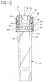
- FIG. 2 is a side elevational view of container 12 with cap 14 secured thereto, and shows the interaction between container 12 and cap 14 .
- Cap 14 includes a top surface 54 , a bottom stop ledge 56 and an annular outer skirt 58 extending from top surface 54 to bottom stop ledge 56 .
- Annular outer skirt 58 has an outer wall surface 60 and an inner wall surface 62 , and a shield 66 extending from the bottom of outer wall surface 60 of annular outer skirt 58 having an outer surface or circumference 76 .
- cap 14 also has an inner annular recessed skirt 64 that extends from top portion 54 to a bottom surface 63 .
- Recessed skirt 64 defines a compartment or cup area 65 in top portion 54 of cap 14 .
- Inner wall surface 62 of annular outer skirt 58 and inner annular recessed skirt 64 are spaced from each other to define an annular space 68 .
- Cap 14 further includes a plurality of circumferentially spaced protrusions 70 positioned on inner wall surface 62 and a sealing ring 67 positioned on recessed skirt 64 .
- any fluid that migrates between upper surface edge 43 and bottom stop ledge 56 is directed in a downward direction along container 12 by an inner surface 81 of shield 66 to minimize radial spray.
- spaces 82 and 83 remain between integral lip portion 34 and skirts 58 and 64 , respectively, to prevent blood on lip portion 34 from being (i) wiped upward or splattered when cap 14 is removed from container 12 and (ii) pushed down towards bottom stop ledge 56 when cap 14 is secured to container 12 .
- any fluid in well 42 is substantially contained by upper surface edge 43 of cap seating flange 40 and bottom stop ledge 56 of cap 14 .
- Outer surface 76 of shield 66 does not cover cap seating flange 40 of container 12 completely, as shown in FIG. 3, so that when the capped assembly is centrifuged the load is on flange 40 and cap 14 is not loosened.
- cap 14 is snapped onto upper portion 28 of container 12 and is removably secured to container 12 by protrusions 70 and sealing ring 67 as they bear respectfully against lower edge 52 of locking ring 48 and inner surface 27 of container 12 .
- the position of protrusions 70 in respective indents 95 as shown in FIG. 3 and the cross-sectional view in FIG. 4 taken along line 4-4 in FIG. 3, provide the locking action between container 12 and cap 14 .
- the position of protrusions 70 and sealing ring 67 of cap 14 with container 12 forms space 82 between outer surface 24 of upper portion 28 and inner wall surface 62 of annular outer skirt 58 . Therefore, wiping down of any fluid on the outer surface 24 of upper portion 28 is substantially prevented.
- bottom stop edge 56 bears against flange upper surface 43 to provide a stop and insure a proper sealing depth for sealing ring 67 on inner surface 27 .
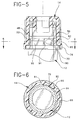
- FIGS. 5 and 6 show container 12 with cap 14 in an unlocked position. More particularly, FIG. 5 is another cross-sectional view of collection assembly 10 and FIG. 6 is a cross-sectional view taken along line 6-6 in FIG. 5.
- cap 14 is unsecured from the container in a twist-off manner by applying a rotational force about a longitudinal axis 80 while holding container 12 . Rotation of cap 14 with respect to container 12 causes protrusion 70 on cap 14 to climb out of indent 95 up incline 91 onto top surface 92 of riser 90 , as shown in FIGS. 5 and 6.
- protrusion 70 is in the location shown in FIGS.
- cap 14 is unsecured from container 12 and can be slid off of container 12 since protrusion 70 is lifted to be level with the junction between upper edge 50 and lower edge 52 of locking ring 48 and merely has to be slid down upper edge 50 .
- the rotational force applied to cap 14 to move protrusion 70 up onto riser 90 can be bi-directional, that is clockwise or counter-clockwise.
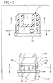
- FIGS. 7, 8 and 9 are various views of cap 14 and container 12 , with cap 14 removed from container 12 . More particularly, FIG. 8 is a cross-sectional view taken along line 8-8, and FIG. 9 is a cross-sectional view taken along line 9-9 in FIG. 7. These figures more clearly show the preferred embodiment of collection assembly 10 with three protrusions 70 on cap 14 and three risers on the outer surface of upper portion 28 of container 12 .
- the collection assembly of the invention may be made of a molded thermoplastic material so that the specimen collected may be readily viewed.
- Representative materials include, for example, polyethylene, polypropylene and polyvinyl chloride.
- the collection container may incorporate a hydrophilic material or a silicon, or a texture may be applied to the internal surface thereof for enhancing the flow and mixing of blood introduced into the container.
- caps which are colored to define specific forms of fluid collection containers containing materials for one reason or another or for defining the kind of examination to be conducted on the specimen collected, transparent caps may be provided. Also, it should be noted that the dimensions of the container are such as to provide space for labeling which may be important for identifying the collected specimens.
Landscapes
- Health & Medical Sciences (AREA)
- Life Sciences & Earth Sciences (AREA)
- Engineering & Computer Science (AREA)
- General Health & Medical Sciences (AREA)
- Heart & Thoracic Surgery (AREA)
- Veterinary Medicine (AREA)
- Public Health (AREA)
- Hematology (AREA)
- Animal Behavior & Ethology (AREA)
- Surgery (AREA)
- Molecular Biology (AREA)
- Medical Informatics (AREA)
- Pathology (AREA)
- Biomedical Technology (AREA)
- Physics & Mathematics (AREA)
- Biophysics (AREA)
- Chemical & Material Sciences (AREA)
- Clinical Laboratory Science (AREA)
- Mechanical Engineering (AREA)
- Chemical Kinetics & Catalysis (AREA)
- Analytical Chemistry (AREA)
- Manufacturing & Machinery (AREA)
- Dermatology (AREA)
- Measurement Of The Respiration, Hearing Ability, Form, And Blood Characteristics Of Living Organisms (AREA)
- Investigating Or Analysing Biological Materials (AREA)
- Sampling And Sample Adjustment (AREA)
- Closures For Containers (AREA)
- Medicines Containing Material From Animals Or Micro-Organisms (AREA)
Description
and
and
wherein said solid protrusion is adapted to bear against said locking ring of said container and characterised by
said outer skirt on said cap is adapted to extend over and beyond said trough in said cap seating flange so that said bottom stop ledge contacts said cap seating flange, when said cap is locked on said open top portion of said container.
Claims (7)
- A collection assembly (10) comprising:a cap (14) comprising a closed top portion including a top surface (54) and an open bottom portion; said cap (14) further comprising:an outer skirt (58) extending from said closed top surface (54) over a bottom stop ledge (56) at said open bottom portion to a shield (66) and having an inner surface (62);a closed inner skirt (64) surrounded by said outer skirt (58) and extending from said closed top surface (54) toward said open bottom portion to a bottom surface (63);
and a protrusion (70) extending from said inner surface (62) of said outer skirt (58);
anda container (12) comprising an open top portion (28), a closed bottom portion (30) and a sidewall having an outer surface (24); said container (12) further comprising:an integral lip (34) extending from said open top portion (28);a cap seating flange (40) on said outer surface (24) of said container (12) positioned where said integral lip (34) extends from said top portion (28);a locking ring (48) on said outer surface (24) of said container (12) positioned between said integral lip (34) and said cap seating flange (40) having an upper edge (50) and a lower edge (52); wherein said solid protrusion (70) is adapted to bear against said locking ring (48) of said container (12) and characterised by lifting means (90) on said outer surface (24) of said container (12) positioned between said locking ring (48) and said cap seating flange (40), said lifting means (90) interacting with said protrusion (70) on said cap (14) to lift said protrusion (70) over said locking ring (48) and facilitate removal of said cap (14) from said container (12) upon rotation of said cap (14); said cap seating flange (40) containing a trough (42) wherein
said outer skirt (58) on said cap (14) is adapted to extend over and beyond said trough (42) in said cap seating flange (40) so that said bottom stop ledge (56) contacts said cap seating flange (40), when said cap (14) is locked on said open top portion of said container (12). - The assembly (10) of Claim 1, wherein said lifting means (90) comprises a riser located on said outer surface (24) of said container (12) positioned between said locking ring (48) and said cap seating flange (40).
- The assembly (10) of Claim 2, wherein said riser comprises a pair of inclines (91) and a top surface (92), said top surface (92) being flush with a junction between said upper edge (50) and said lower edge (52) of said locking ring (48) to permit said protrusion (70) on said cap (14) to slide up one of said inclines (91) onto said top surface (92) and down an upper edge (50) of said locking ring (48) to facilitate removal of said cap (14) from said container (12) upon rotation of said cap (14).
- The assembly (10) of Claim 1, wherein said cap (14) further comprises a sealing ring (67) on said closed inner skirt (64) of said cap (14), wherein said sealing ring (48) bears against the inner surface of said integral lip (34) of said container (12) when said cap (14) is locked on said open top portion (28) of said container (12).
- The assembly (10) of Claim 1, wherein said lifting means (90) comprises a plurality of risers located on said outer surface (24) of said container (12), each of said risers being positioned between said locking ring (48) and said cap seating flange (40).
- The assembly (10) of Claim 5, wherein each of said plurality of risers comprises a pair of inclines (91) and a top surface (92), said top surface (92) being flush with a junction between said upper edge (50) and said lower edge (52) of said locking ring (48) to permit said protrusion (70) on said cap (14) to slid up one of said inclines (91) onto said top surface (92) and down an upper edge (50) of said locking ring (48) to facilitate removal of said cap (14) from said container (12) upon rotation of said cap (14).
- The assembly (10) of Claim 5, wherein said cap (14) further comprises a sealing ring (67) on said closed inner skirt (64) of said cap (14), wherein said sealing ring (67) bears against the inner surface of said integral lip (34) of said container (12) and said bottom stop ledge (56) contacts said cap seating flange (40) when said cap (14) is locked on said open top portion (28) of said container (12).
Applications Claiming Priority (3)
| Application Number | Priority Date | Filing Date | Title |
|---|---|---|---|
| US08/225,029 US5527513A (en) | 1994-04-08 | 1994-04-08 | Collection assembly |
| US236288 | 1994-04-29 | ||
| US08/236,288 US5552117A (en) | 1994-04-08 | 1994-04-29 | Collection assembly having a cap lifting mechanism |
Publications (3)
| Publication Number | Publication Date |
|---|---|
| EP0679366A2 EP0679366A2 (en) | 1995-11-02 |
| EP0679366A3 EP0679366A3 (en) | 1996-06-05 |
| EP0679366B1 true EP0679366B1 (en) | 1999-09-15 |
Family
ID=51946299
Family Applications (2)
| Application Number | Title | Priority Date | Filing Date |
|---|---|---|---|
| EP95301926A Expired - Lifetime EP0679366B1 (en) | 1994-04-08 | 1995-03-23 | Collection assembly |
| EP95301927A Expired - Lifetime EP0676171B1 (en) | 1994-04-08 | 1995-03-23 | Collection assembly |
Family Applications After (1)
| Application Number | Title | Priority Date | Filing Date |
|---|---|---|---|
| EP95301927A Expired - Lifetime EP0676171B1 (en) | 1994-04-08 | 1995-03-23 | Collection assembly |
Country Status (6)
| Country | Link |
|---|---|
| US (2) | US5527513A (en) |
| EP (2) | EP0679366B1 (en) |
| JP (2) | JP2648290B2 (en) |
| AU (2) | AU681486B2 (en) |
| CA (2) | CA2144920C (en) |
| DE (2) | DE69518102T2 (en) |
Families Citing this family (43)
| Publication number | Priority date | Publication date | Assignee | Title |
|---|---|---|---|---|
| US5893476A (en) * | 1997-04-16 | 1999-04-13 | Estar Technologies Ltd. | Sealing closure for sample tubes |
| US5876137A (en) * | 1997-05-19 | 1999-03-02 | Rexam Cosmetic Packaging, Inc. | Outer shell for a cosmetic container for preventing accidental removal of the shell's cover |
| US5955032A (en) * | 1997-09-12 | 1999-09-21 | Becton Dickinson And Company | Collection container assembly |
| US5948365A (en) * | 1997-09-12 | 1999-09-07 | Becton Dickinson And Company | Collection container assembly |
| US5947309A (en) * | 1998-03-09 | 1999-09-07 | Premium Plastics, Inc. | Container-closure combination with improved sealing feature |
| US6153238A (en) * | 1999-04-22 | 2000-11-28 | Schreiber Foods, Inc. | Packaged decorator cheese product with cap |
| US6716396B1 (en) * | 1999-05-14 | 2004-04-06 | Gen-Probe Incorporated | Penetrable cap |
| US6426049B1 (en) * | 1999-07-09 | 2002-07-30 | Becton, Dickinson And Company | Collection assembly |
| US6095358A (en) * | 1999-07-26 | 2000-08-01 | Marino; Michael | Anti-creeping cap for container |
| USD424440S (en) * | 1999-08-06 | 2000-05-09 | Becton, Dickinson And Company | Tube cap |
| US6170719B1 (en) | 1999-08-06 | 2001-01-09 | Becton Dickinson And Company | Medical safety closure |
| EA003682B1 (en) | 1999-09-14 | 2003-08-28 | Смитклайн Бичам Корпорейшн | Container closure system |
| CZ20024006A3 (en) * | 2000-06-09 | 2003-11-12 | Diabetes Diagnostics, Inc. | Cap for incision device and incision device per se |
| US6491709B2 (en) * | 2000-12-22 | 2002-12-10 | Becton, Dickinson And Company | Alternate-site lancer |
| US20040098010A1 (en) * | 2001-10-22 | 2004-05-20 | Glenn Davison | Confuser crown skin pricker |
| AU2004200523A1 (en) * | 2003-02-19 | 2004-09-09 | Bayer Healthcare, Llc | Endcap for Lancing Device and Method of Use |
| CA2465804A1 (en) * | 2003-04-28 | 2004-10-28 | Elena Trkulja | Aerosol collection cap and container |
| US20050042577A1 (en) | 2003-08-19 | 2005-02-24 | Kvitrud James R. | Dental crown forms and methods |
| BRPI0509527A (en) * | 2004-04-01 | 2007-09-18 | Bayer Healthcare Llc | tip for vacuum lancing device |
| GB0409354D0 (en) * | 2004-04-27 | 2004-06-02 | Owen Mumford Ltd | Removal of needles |
| US7854343B2 (en) * | 2005-03-10 | 2010-12-21 | Labcyte Inc. | Fluid containers with reservoirs in their closures and methods of use |
| GB2432357B (en) * | 2005-11-16 | 2010-12-29 | Dubois Ltd | Packaging article |
| US7891511B2 (en) * | 2005-11-22 | 2011-02-22 | Portola Packaging, Inc. | Scallop cap closures |
| GB0524604D0 (en) * | 2005-12-02 | 2006-01-11 | Owen Mumford Ltd | Injection method and apparatus |
| GB2434103B (en) | 2006-01-12 | 2009-11-25 | Owen Mumford Ltd | Lancet firing device |
| JP4912829B2 (en) * | 2006-10-17 | 2012-04-11 | 日本クラウンコルク株式会社 | Container lid |
| WO2008078808A1 (en) * | 2006-12-27 | 2008-07-03 | Medibic | Vacuum blood collection tube |
| EP1995182A1 (en) * | 2007-05-25 | 2008-11-26 | F.Hoffmann-La Roche Ag | A sealing cap for a fluid container and a blood collection device |
| CN101382510B (en) * | 2007-09-06 | 2012-07-25 | 清华大学 | Multi-bottle detecting container |
| ES2877598T3 (en) * | 2008-03-05 | 2021-11-17 | Becton Dickinson Co | Co-molded pierceable plug and method of making the same |
| EP3685748A1 (en) | 2008-03-05 | 2020-07-29 | Becton, Dickinson and Company | Capillary action collection container assembly |
| GB2465390A (en) | 2008-11-17 | 2010-05-19 | Owen Mumford Ltd | Syringe needle cover remover |
| JP5140620B2 (en) * | 2009-02-27 | 2013-02-06 | 藤森工業株式会社 | Liquid sample storage device and liquid sample measurement method |
| DE102009002074A1 (en) * | 2009-04-01 | 2010-10-07 | Henkel Ag & Co. Kgaa | locking system |
| USD645972S1 (en) | 2010-01-25 | 2011-09-27 | Becton, Dickinson And Company | Specimen collection container having a label |
| US8973293B2 (en) | 2010-11-19 | 2015-03-10 | Becton, Dickinson And Company | Specimen container label for automated clinical laboratory processing systems |
| US8460620B2 (en) | 2010-12-03 | 2013-06-11 | Becton, Dickinson And Company | Specimen collection container assembly |
| CA2742629A1 (en) * | 2011-06-09 | 2012-12-09 | Joseph BIDWELL | A case for protecting the bristles of a paintbrush |
| US8950617B2 (en) * | 2012-07-12 | 2015-02-10 | Universiti Putra Malaysia | Non-penetrative blood container and apparatus for vacuuming the same |
| CN107207134B (en) * | 2015-03-05 | 2020-08-04 | 万通集团公司 | Accessory and top cover therefor |
| US20160074018A1 (en) * | 2015-11-23 | 2016-03-17 | Michelle Marie Lependorf | Urine Specimen Collection Kit With Retractable/Adjustable Handle and Sponge |
| WO2019215504A2 (en) * | 2018-05-07 | 2019-11-14 | Toho Technology Corporation | Capped container |
| US11628989B2 (en) * | 2021-03-18 | 2023-04-18 | Mike C Sanchez | Child-resistant container and closure |
Family Cites Families (40)
| Publication number | Priority date | Publication date | Assignee | Title |
|---|---|---|---|---|
| US2039037A (en) * | 1935-01-28 | 1936-04-28 | E Q Benbow | Tube closure |
| US2193226A (en) * | 1937-01-25 | 1940-03-12 | Cherry Burrell Corp | Closure for containers |
| US2867351A (en) * | 1956-06-01 | 1959-01-06 | Jr Cameron Macleod | Body retaining self loosening cover and can |
| US3136458A (en) * | 1961-02-27 | 1964-06-09 | Ruetz Karl | Container including a neck with a pouring opening and closing device for the same |
| US3372834A (en) * | 1966-01-24 | 1968-03-12 | Robert A. Ayotte | Container and closure assembly |
| US3308039A (en) * | 1966-02-15 | 1967-03-07 | Allergan Pharma | Disposable culturing device |
| FR1520693A (en) * | 1967-03-01 | 1968-04-12 | Oreal | New closure device for vials or similar containers |
| US3419179A (en) * | 1967-06-07 | 1968-12-31 | Brunswick Corp | Captive cap specimen vial |
| BE790608A (en) * | 1971-10-27 | 1973-02-15 | Anchor Hocking Corp | WATERPROOF CAP FOR CLOSING A CONTAINER OF |
| US3784047A (en) * | 1972-05-04 | 1974-01-08 | A Cooper | Safety closure cap |
| CH565682A5 (en) * | 1973-08-24 | 1975-08-29 | Nestle Sa | |
| US3902477A (en) * | 1973-09-26 | 1975-09-02 | Becton Dickinson Co | Blood specimen container |
| DE2353742C2 (en) * | 1973-10-26 | 1983-08-04 | Robert Finke Kunststoff-Spritzguss-Werk, 5950 Finnentrop | Cap closure for bottles and the like with child protection device |
| US3913783A (en) * | 1974-01-17 | 1975-10-21 | Alfred Cooper | Safety closure cap with retaining feet |
| US3901400A (en) * | 1974-02-04 | 1975-08-26 | Continental Can Co | Childproof closure |
| US3910444A (en) * | 1974-06-06 | 1975-10-07 | Clark Mfg Co J L | Container having snap-on, twist-off cap |
| US3945525A (en) * | 1974-06-06 | 1976-03-23 | American Hospital Supply Corporation | Closure system for medical liquid container having low-torque breakaway ring |
| US3982651A (en) * | 1974-11-18 | 1976-09-28 | W. Braun Company | Container and closure cap therefor |
| US4051974A (en) * | 1976-02-18 | 1977-10-04 | Orange Products, Inc. | Sealing apparatus |
| US4117946A (en) * | 1976-11-15 | 1978-10-03 | Milton Kessler | Plastic cap for widemouthed containers |
| US4204605A (en) * | 1978-09-08 | 1980-05-27 | The West Company | Container-closure assembly |
| US4171057A (en) * | 1978-10-30 | 1979-10-16 | Sunbeam Plastics Corporation | Child-resistant medicine vial |
| GB2041892A (en) * | 1979-02-09 | 1980-09-17 | United Glass Ltd | Containers & Closures |
| GB2063226B (en) * | 1979-11-13 | 1983-08-10 | Ug Closures & Plastics Ltd | Closure |
| US4298129A (en) * | 1980-05-02 | 1981-11-03 | Morton Stull | Childproof, snap-on, twist-off safety cap and container |
| US4335823A (en) * | 1981-01-26 | 1982-06-22 | Sunbeam Plastics Corporation | Child-resistant package |
| DK147077C (en) * | 1981-11-16 | 1984-09-10 | Nunc As | CELL CULTURE CONTAINER |
| US4390111A (en) * | 1982-02-08 | 1983-06-28 | Robbins Scientific Corporation | Sealable vial |
| US4576185A (en) * | 1983-12-05 | 1986-03-18 | Terumo Medical Corporation | Collection device for capillary blood |
| US4577769A (en) * | 1985-03-26 | 1986-03-25 | The Drackett Company | Child resistant container |
| DE3541041A1 (en) * | 1985-11-19 | 1987-05-21 | Sarstedt Kunststoff | BLOOD COLLECTOR |
| FR2600043B1 (en) * | 1986-06-17 | 1989-04-21 | Astra Plastique | WATERPROOF SCREW CAP FOR CONTAINER THREADED NECK. |
| FR2620424B1 (en) * | 1987-09-15 | 1989-12-15 | Morel Simone | REMOVABLE HOOD CONTAINER WITH ALIGNED SIDE GENERATORS |
| JPH074207Y2 (en) * | 1987-09-24 | 1995-02-01 | 東京ライト工業株式会社 | Container with lid |
| JPH0617682Y2 (en) * | 1988-02-29 | 1994-05-11 | フィグラ株式会社 | Container closure device |
| US5100013A (en) * | 1990-01-29 | 1992-03-31 | Extrudiplast Investments, S.A. | Plastic closure |
| DE9201222U1 (en) * | 1991-05-17 | 1992-04-23 | KABE-Labortechnik GmbH, 5223 Nümbrecht | Sample tube and end cap |
| CA2067695C (en) * | 1991-06-06 | 1997-07-08 | James A. Burns | Blood microcollection tube assembly |
| US5384096A (en) * | 1993-05-12 | 1995-01-24 | Becton, Dickinson And Company | Microcollection tube assembly |
| US5320233A (en) * | 1993-08-30 | 1994-06-14 | Aluminum Company Of America | Tamper evident lug cap |
-
1994
- 1994-04-08 US US08/225,029 patent/US5527513A/en not_active Expired - Lifetime
- 1994-04-29 US US08/236,288 patent/US5552117A/en not_active Expired - Lifetime
-
1995
- 1995-03-17 CA CA002144920A patent/CA2144920C/en not_active Expired - Lifetime
- 1995-03-17 CA CA002144919A patent/CA2144919C/en not_active Expired - Lifetime
- 1995-03-20 AU AU14963/95A patent/AU681486B2/en not_active Expired
- 1995-03-23 DE DE69518102T patent/DE69518102T2/en not_active Expired - Lifetime
- 1995-03-23 DE DE69512124T patent/DE69512124T2/en not_active Expired - Lifetime
- 1995-03-23 EP EP95301926A patent/EP0679366B1/en not_active Expired - Lifetime
- 1995-03-23 EP EP95301927A patent/EP0676171B1/en not_active Expired - Lifetime
- 1995-03-28 AU AU16131/95A patent/AU679614B2/en not_active Expired
- 1995-04-07 JP JP7082642A patent/JP2648290B2/en not_active Expired - Lifetime
- 1995-04-14 JP JP7088995A patent/JP2642080B2/en not_active Expired - Lifetime
Also Published As
| Publication number | Publication date |
|---|---|
| DE69512124D1 (en) | 1999-10-21 |
| US5527513A (en) | 1996-06-18 |
| JP2648290B2 (en) | 1997-08-27 |
| EP0676171B1 (en) | 2000-07-26 |
| EP0676171A2 (en) | 1995-10-11 |
| EP0679366A3 (en) | 1996-06-05 |
| CA2144920A1 (en) | 1995-10-30 |
| AU1613195A (en) | 1995-11-09 |
| JPH07275224A (en) | 1995-10-24 |
| EP0676171A3 (en) | 1996-06-05 |
| DE69518102T2 (en) | 2001-03-22 |
| JP2642080B2 (en) | 1997-08-20 |
| AU681486B2 (en) | 1997-08-28 |
| CA2144919C (en) | 1998-08-18 |
| US5552117A (en) | 1996-09-03 |
| DE69512124T2 (en) | 2000-05-25 |
| DE69518102D1 (en) | 2000-08-31 |
| CA2144920C (en) | 1999-04-06 |
| AU1496395A (en) | 1995-10-19 |
| EP0679366A2 (en) | 1995-11-02 |
| AU679614B2 (en) | 1997-07-03 |
| CA2144919A1 (en) | 1995-10-09 |
| JPH07299052A (en) | 1995-11-14 |
Similar Documents
| Publication | Publication Date | Title |
|---|---|---|
| EP0679366B1 (en) | Collection assembly | |
| US5384096A (en) | Microcollection tube assembly | |
| EP0696434B1 (en) | Collection assembly | |
| EP0668054B1 (en) | Specimen transporting and processing system | |
| US4300404A (en) | Liquid specimen container | |
| US6426049B1 (en) | Collection assembly | |
| US20030053938A1 (en) | Liquid specimen collection container | |
| EP0189118A2 (en) | Blood collection assembly | |
| CA2124705C (en) | Liquid specimen collector with removable extraction device | |
| EP0189153B1 (en) | Blood collection assembly | |
| CA2265187C (en) | Collection assembly | |
| NZ214710A (en) | Blood collection assembly: cap removably held or permanently locked to blood collector |
Legal Events
| Date | Code | Title | Description |
|---|---|---|---|
| PUAI | Public reference made under article 153(3) epc to a published international application that has entered the european phase |
Free format text: ORIGINAL CODE: 0009012 |
|
| AK | Designated contracting states |
Kind code of ref document: A2 Designated state(s): DE FR GB IT SE |
|
| PUAL | Search report despatched |
Free format text: ORIGINAL CODE: 0009013 |
|
| AK | Designated contracting states |
Kind code of ref document: A3 Designated state(s): DE FR GB IT SE |
|
| 17P | Request for examination filed |
Effective date: 19961129 |
|
| 17Q | First examination report despatched |
Effective date: 19971105 |
|
| GRAG | Despatch of communication of intention to grant |
Free format text: ORIGINAL CODE: EPIDOS AGRA |
|
| GRAH | Despatch of communication of intention to grant a patent |
Free format text: ORIGINAL CODE: EPIDOS IGRA |
|
| GRAH | Despatch of communication of intention to grant a patent |
Free format text: ORIGINAL CODE: EPIDOS IGRA |
|
| GRAA | (expected) grant |
Free format text: ORIGINAL CODE: 0009210 |
|
| AK | Designated contracting states |
Kind code of ref document: B1 Designated state(s): DE FR GB IT SE |
|
| PG25 | Lapsed in a contracting state [announced via postgrant information from national office to epo] |
Ref country code: SE Free format text: THE PATENT HAS BEEN ANNULLED BY A DECISION OF A NATIONAL AUTHORITY Effective date: 19990915 |
|
| REF | Corresponds to: |
Ref document number: 69512124 Country of ref document: DE Date of ref document: 19991021 |
|
| ITF | It: translation for a ep patent filed | ||
| ET | Fr: translation filed | ||
| PLBE | No opposition filed within time limit |
Free format text: ORIGINAL CODE: 0009261 |
|
| STAA | Information on the status of an ep patent application or granted ep patent |
Free format text: STATUS: NO OPPOSITION FILED WITHIN TIME LIMIT |
|
| 26N | No opposition filed | ||
| REG | Reference to a national code |
Ref country code: GB Ref legal event code: IF02 |
|
| PGFP | Annual fee paid to national office [announced via postgrant information from national office to epo] |
Ref country code: FR Payment date: 20050321 Year of fee payment: 11 |
|
| PGFP | Annual fee paid to national office [announced via postgrant information from national office to epo] |
Ref country code: IT Payment date: 20060331 Year of fee payment: 12 |
|
| REG | Reference to a national code |
Ref country code: FR Ref legal event code: ST Effective date: 20061130 |
|
| PG25 | Lapsed in a contracting state [announced via postgrant information from national office to epo] |
Ref country code: FR Free format text: LAPSE BECAUSE OF NON-PAYMENT OF DUE FEES Effective date: 20060331 |
|
| PG25 | Lapsed in a contracting state [announced via postgrant information from national office to epo] |
Ref country code: IT Free format text: LAPSE BECAUSE OF NON-PAYMENT OF DUE FEES Effective date: 20070323 |
|
| PGFP | Annual fee paid to national office [announced via postgrant information from national office to epo] |
Ref country code: GB Payment date: 20140327 Year of fee payment: 20 |
|
| PGFP | Annual fee paid to national office [announced via postgrant information from national office to epo] |
Ref country code: DE Payment date: 20140327 Year of fee payment: 20 |
|
| REG | Reference to a national code |
Ref country code: DE Ref legal event code: R071 Ref document number: 69512124 Country of ref document: DE |
|
| REG | Reference to a national code |
Ref country code: GB Ref legal event code: PE20 Expiry date: 20150322 |
|
| PG25 | Lapsed in a contracting state [announced via postgrant information from national office to epo] |
Ref country code: GB Free format text: LAPSE BECAUSE OF EXPIRATION OF PROTECTION Effective date: 20150322 |