EP0678656A2 - Ram-type blowout preventor - Google Patents
Ram-type blowout preventor Download PDFInfo
- Publication number
- EP0678656A2 EP0678656A2 EP95301917A EP95301917A EP0678656A2 EP 0678656 A2 EP0678656 A2 EP 0678656A2 EP 95301917 A EP95301917 A EP 95301917A EP 95301917 A EP95301917 A EP 95301917A EP 0678656 A2 EP0678656 A2 EP 0678656A2
- Authority
- EP
- European Patent Office
- Prior art keywords
- piston
- cylinder
- ram
- annular
- blowout preventer
- Prior art date
- Legal status (The legal status is an assumption and is not a legal conclusion. Google has not performed a legal analysis and makes no representation as to the accuracy of the status listed.)
- Granted
Links
Images


Classifications
-
- E—FIXED CONSTRUCTIONS
- E21—EARTH DRILLING; MINING
- E21B—EARTH DRILLING, e.g. DEEP DRILLING; OBTAINING OIL, GAS, WATER, SOLUBLE OR MELTABLE MATERIALS OR A SLURRY OF MINERALS FROM WELLS
- E21B29/00—Cutting or destroying pipes, packers, plugs, or wire lines, located in boreholes or wells, e.g. cutting of damaged pipes, of windows; Deforming of pipes in boreholes or wells; Reconditioning of well casings while in the ground
- E21B29/08—Cutting or deforming pipes to control fluid flow
-
- E—FIXED CONSTRUCTIONS
- E21—EARTH DRILLING; MINING
- E21B—EARTH DRILLING, e.g. DEEP DRILLING; OBTAINING OIL, GAS, WATER, SOLUBLE OR MELTABLE MATERIALS OR A SLURRY OF MINERALS FROM WELLS
- E21B33/00—Sealing or packing boreholes or wells
- E21B33/02—Surface sealing or packing
- E21B33/03—Well heads; Setting-up thereof
- E21B33/06—Blow-out preventers, i.e. apparatus closing around a drill pipe, e.g. annular blow-out preventers
- E21B33/061—Ram-type blow-out preventers, e.g. with pivoting rams
- E21B33/062—Ram-type blow-out preventers, e.g. with pivoting rams with sliding rams
- E21B33/063—Ram-type blow-out preventers, e.g. with pivoting rams with sliding rams for shearing drill pipes
Definitions
- This invention relates generally to ram-type blow- out preventers, and, more particularly, to actuators for the rams of a blowout preventer either for shearing a pipe extending through the bore of the blowout preventer and then sealing across the bore or for seating around a pipe extending through the bore. Still more particularly, the invention relates to an apparatus for enhancing the pressure area and limiting the stroke of the operating piston of the actuator.
- a ram-type blowout preventer comprises a housing connected to a wellhead with the housing having a bore which is in alignment with the wellbore.
- Rams are moveable within guideways extending transversely from the bore between an outer position removed from the bore and inner position across the bore and engaging with one another to seal off the bore.
- the inner ends of the rams have recesses for sealing around the pipe suspended within the bore.
- the inner ends of the rams include blades to shear the pipe and also seals which may be flat or otherwise complimentary for sealing across the open bore after the pipe is sheared. Upon inward movement of the rams into the bore, the sealing engagement between the seals carried on the rams effectively terminates any fluid flow through the bore.
- a hydraulically actuated cylinder having a piston interconnected to the respective ram by means of a shaft or a "stem” effects the movement of the rams into sealing engagement.
- the stem is provided with stem packings or seals disposed about the stem to prevent pressure and fluid in the bore from being communicated along the stem into the hydraulic circuit of the cylinder.
- the actuator is rigidly affixed to one end of the housing and extends outwardly in the sarne direction on either side of a respective ram stem.
- the actuator includes a bonnet in which is disposed a piston and cylinder with the bonnet being affixed to the housing by means of bonnet bolts.
- the cylinder is connected to a hydraulic circuit for providing fluid under pressure to move the piston within the cylinder.
- the piston is disposed on the stem to reciprocate the ram.
- Typical shear ram blowout preventers are shown in U.S. Patent Nos. 3,946,806; 4,043,389; 4,313,496; and 4,132,267.
- Typical pipe ram blowout preventers are shown in U.S. Patent Nos. 4,492,359 and 4,504,037.
- a preferred ram-type blowout preventer is shown on pages 637-645 of the Composite Catalog of Oilfield Equipment and Services, 1992-93, published by World Oil.
- a substantial pressure force must be applied to the shear rams of a shear ram blowout preventer to shear the pipe extending through the bore of the preventer.
- Various means have been employed in the prior art actuator to ensure that the actuator provided adequate shear force.
- a booster piston and cylinder may be piggy backed onto the primary operating piston and cylinder to ensure sufficient force to both shear the pipe and seal the bore.
- the actuators for the rams are designed for removal of the rams in the field to change the pipe rams or shear rams of the blowout preventer.
- One method is the use of ram change pistons and cylinders whereupon removal of the bonnet bolts, the ram change pistons and cylinders are hydraulically actuated causing the bonnet to travel radially inward and outward with respect to the blowout preventer housing in a manner like that of the ram operating piston.
- the pipe ram or shear ram Upon moving the bonnet into the outward position because it is no longer restrained by the bonnet bolts, the pipe ram or shear ram, as the case may be, is also pulled along the ram guideway outwards of the blowout preventer bore so as to be removed from the housing and thus exposed and rendered accessible for servicing or replacement.
- the substantial operating piston force required to shear the pipe in a shear ram-type blowout preventer is much greater than the amount of force required to seal the open bore after the pipe has been sheared. This over capacity force on the elastomeric seals of the shear ram reduces the life of the seals. It is preferred that the operating piston force on the seals be reduced after the shear rams have sheared the pipe. However, the hydraulic pressure on the operating piston frequently remains at the same high level during both the shearing and sealing operations.
- the actuator of the present invention includes an operating cylinder disposed between a bonnet and a cylinder head for receiving an operating piston having a stem for transmitting relative motion to the ram of a ram-type blowout preventer.
- the actuatorfurther includes a booster and stroke limiting apparatus disposed around the circumference of the operating piston.
- the booster and stroke limiting apparatus is in the form of an annular member having first and second annular flanges extending radially inward to form a channel therebetween. The channel slidingly receives the circumference of the piston and allows the piston to move between the first and second annular flanges.
- the booster and stroke limiting apparatus allows the actuator to be used either with a shear ram blow- out preventer or a pipe ram blowout preventer.
- a shear ram blowout preventer the annular ring is positioned around the operating piston such that the first annular flange is most remote from the ram and the second annularflange is radially inward of the first annular flange.
- the first annular flange of the annular member engages the piston to increase the annular pressure area of the piston within the operating cylinder.
- the pipe within the shear ram blowout preventer is sheared.
- the shearing stroke ends upon the annular member engaging the bottom of the operating cylinder thus allowing the hydraulic pressure only to be applied to the smaller pressure area of the piston.
- the piston continues to travel within the channel of the annular member until the piston also engages the bottom of the cylinder. During this sealing stroke of the piston, the seals of the shear rams sealingly engage.
- the annular member is reversed or turned over such that the second annular flange is most remote from the pipe ram with the first annular flange being radially inward of the second annular flange.
- the second annular flange engages the piston to increase the annular pressure area.
- the initial sealing stroke ends upon the annular member engaging the bottom of the cylinder.
- the piston continues to travel within the channel until the piston engages the first annular flange.
- Such engagement of the piston on the first annular flange prevents the piston from engaging the bottom of the cylinder thereby shortening the stroke of the piston when compared to its stroke in a shear ram blowout preventer.
- the actuator of the present invention has many advantages over the prior art.
- the actuator may be used either with a shear ram blowout preventer or a pipe ram blowout preventer merely upon the appropriate positioning of the booster and stroke limiting apparatus around the operating piston.
- the booster and stoke limiting apparatus allows a large pressure force to be applied to the shear rams during the shearing stroke and a reduced pressure force to be applied to the seals of the shear rams during the sealing stroke.
- the booster and stroke limiting apparatus shortens the stroke of the operating piston.
- the actuator of the present invention is lighter in weight and allows an operating cylinder with a larger diameter than that of the prior art so as to increase the annular pressure area for the application of a greater pressure force on the rams of a shear ram blowout preventer.
- Blowout preventer 10 includes a body or housing 14 with a vertical bore 16 extending therethrough. Pipe string 12 passes through bore 16 and extends downwardly into the wellbore. Housing 14 may include flanges (not shown) so that blowout preventer 10 may be connected in a wellhead stack.
- Ram guideways 18, 20 extend transversely outward from opposite sides of bore 16. First and second shearing rams 22 and 24 are positioned for reciprocation within guideways 18 and 20, respectively.
- Hydraulic actuation means such as actuators 26, 28, are provided to move or extend rams 22, 24, respectively, in response to fluid pressure into bore 16 for shearing that portion of the pipe string 12 which extends through bore 16 and for retracting rams 22, 24 from the bore 16.
- Actuators 26, 28 each include piston and cylinder means, hereinafter described in further detail, and a stem or shaft 30, 31 connecting the pistons to the rams 22, 24, respectively.
- Suitable hydraulic means are provided to deliver fluid under pressure to the piston and cylinder means.
- each shaft 30, 31 includes a head 32 which is received in a slot 34 in the radial outer end of ram 22.
- ram 22 may be easily disconnected from shaft 30 by removing ram 22 from guideway 18 and lifting ram 22 off of the head 32 of shaft 30.
- Each of shear rams 22, 24 includes cutting blades 36, 38.
- Upper cutting blade 36 is disposed on ram 22 and lower cutting blade 38 is disposed on ram 24.
- the cutting blades are integral with the rams.
- cutting blades 36, 38 are positioned so that the cutting edge of lower blade 38 passes just below the cutting edge of upper blade 36 in shearing relation to a section of the pipe string 12.
- Seal means are also mounted on rams 22, 24 adjacent the sides of blades 36, 38.
- Each seal means includes side seals 40 on each side of upper blade 36 and side seals 42 on each side of lower blade 38.
- Side seals 40 are adapted to sealingly engage side seals 42.
- Rams 22, 24 also have top seals 23 which extend from side seals 40, 42 across the upper periphery of the rams to sealingly engage the side seals.
- Blade seal 27 rests below upper blade 36 and sealingly engages side seals 40, 42 and lower blade 38 when rams 22 and 24 are in the closed position of Figure 2.
- Actuator 26 shown in Figure 1, will be described in detail, it being appreciated that the description of actuator 26 is identical to the description of opposed actuator 28.
- Actuator 26 includes a bonnet 50, a cylinder head 52 with a pair of ram change cylinders 54, 56 and an operating cylinder 58 disposed therebetween.
- Ram change cylinders 54, 56 and operating cylinder 58 include cylindrical piston bores 62, 64 and 60, respectively.
- Bonnet 50 and cylinder head 52 each include aligned and opposed counterbores 66, 68 and 70, 72, respectively, for receiving the terminal ends of ram change cylinders 54, 56. Further, bonnet 50 includes a central counterbore 74 and cylinder head 52 includes an annular groove or recess 76 which is aligned and opposed to counterbore 74 so as to receive the respective terminal ends of operating cylinder 58.
- Ram change cylinders 54, 56 each include an exterior annular groove on each of their terminal ends for receiving a seal member 78 for sealingly engaging the cylindrical walls formed by counterbores 66, 68 and 70, 72.
- external annular grooves are disposed on each terminal end of operating cylinder 58 for housing seal members 80, such as o-rings, for sealingly engaging the cylindrical outer walls formed by central counterbore 74 and annular recess 76.
- Bonnet 50 further includes a central bore 82 for slidingly receiving the leading end of shaft 30.
- Packing means 84 is disposed in central bore 82 to sealingly engage the external cylindrical surface of shaft 30.
- An operating piston 90 is disposed on the outer radial end of shaft 30 such that operating piston 90 is disposed within operating cylinder 58.
- a trailing rod 86 is disposed on and extends from the other side of operating piston 90 opposite to shaft 30. Trailing rod 86 is slidingly received within a main bore 88 in cylinder head 52.
- Packing seals 92 are provided in an annular recess in main bore 88 for sealingly engaging the outer cylindrical surface of trailing rod 86.
- operating piston 90 is generally circular in cross section and includes a inwardly radial facing annular bearing surface 98 and an outward radial facing annular bearing surface 100.
- Operating piston 90 also includes an inwardly radial facing annular stop shoulder 110 adjacent shaft 30 and an outwardly radial facing annular stop shoulder 112 adjacent trailing rod 86.
- Inwardly facing stop shoulder 110 is adapted to engage the bottom surface 102 of central counterbore 74 in the closed position as shown in Figure 4.
- Outwardly facing annular stop shoulder 112 is adapted to engage the annular boss 114 formed by annular recess 76 in the open position shown in Figure 3.
- a pair of annular flanges 104, 106 form an annular sealing groove 96 around the outer circumference of operating piston 90.
- Aseal member 97 such as an o-ring, is disposed in groove 96.
- Annularflange 104 has a larger diameter than annular bearing surface 98 thus forming an annular recess 116 and a radially inwardly facing annular stop surface 119.
- the trailing rod 86 extends radially outward of cylinder head 52 through bore 88 and is received within a lock screw housing 117 which is fastened to cylinder head 52 by fastener means such as bolts and nuts 118.
- Lock screw housing 117 includes a central aperture 122 for receiving the terminal end of trailing rod 86.
- Central aperture 122 includes a threaded reduced diameter portion 124 for threadingly receiving a lock screw 120 having external threads 121.
- Manual lock screw 120 includes an enlarged diameter head 126 which is disposed within central aperture 122. The terminal end of head 126 is adapted to abut the terminal end of trailing rod 86.
- the booster and stroke limiting apparatus 130 which forms an adapter mounted around the circumference of operating piston 90.
- the booster and stroke limiting apparatus 130 includes a stroke limiting spacer 132 and a booster piston 134.
- Spacer 132 and booster piston 134 are circular in cross-section and form cylindrical surfaces 136, 138, respectively, at their circumference which are dimensioned to be slidingly received within the cylindrical piston bore 60 of operating cylinder 58.
- Stroke limiting spacer 132 is connected to booster piston 134 by one of several methods. The preferred method is shown in Figures 5A, 5B and 6 where booster piston 138 is an annular ring like member having an annular J-slot groove 140 forming a radially extending annular flange 142. Stroke limiting spacer 132 may comprise a pair of C-shaped members including a radially inwardly facing J-shaped groove 144 forming an inwardly directed annular flange 146. Upon connection of booster piston 138 with stroke limiting spacer 132, inwardly directed annular flange 146 of each C-shaped half of stroke limiting spacer 132 is received within J-slot groove 140 of booster piston 138.
- annular flange 142 of booster piston 138 is received in J-slot groove 144 of each of the C-shaped halves of stroke limiting spacer 132.
- Such interlocking engagement connects piston 134 to spacer 132.
- Stroke limiting spacer 132 includes an external annular groove 148 for receiving an annular seal member 150, such as an o-ring, which when disposed within groove 148 holds the two C-shaped halves of spacer 132 in place around annular booster piston 134.
- Booster piston 134 includes an annular external groove 149 for receiving an annular seal member 151, such as an o-ring.
- An alternative method of connecting spacer 132 and booster piston 134 is to provide cap screws which extend through spacer 132 for threaded engagement in tapped bores in booster piston 134.
- Booster and stroke limiting apparatus 130 is mounted around the outer circumference of operating piston 90.
- Booster piston 134 includes an inwardly radially directed flange 152 forming a radial annular bearing shoulder 154.
- stroke limiting spacer 132 includes an annularflange 157 having an inwardly radially facing annular bearing surface 156.
- annular bearing shoulder 154 and inwardly facing annular bearing surface 156 form an annular channel 160 in which is disposed annular flanges 104, 106 of operating piston 90.
- the seal member 97 disposed in annular groove 96 sealingly engages the inner cylindrical wall 162 of channel 160.
- the sealing member 151 in annular groove 149 sealingly engages the cylindrical bore 60 of operating cylinder 58.
- the height 164 between annular stop shoulder 110 and the face of annular flange 104 is greater than the thickness 166 of annular flange 152 of booster piston 138. Further, the thickness 165 of annular flange 159 is less than the height 167 of shoulder 112 such that shoulder 112 is allowed to engage boss 114 before flange 106 can engage surface 156 of annular flange 157 in the open position shown in Figure 7A.
- the radial height 168 between shoulder 154 and surface 156 is the maximum distance of travel of operating piston 90 within the annular channel 160.
- Operating piston 90 thus has a longer stroke than that of booster and stroke limiting apparatus 130 since operating piston 90 may continue to travel within operating cylinder 58 by continued movement within annular channel 160 even though the booster and stroke limiting apparatus 130 has terminated its shearing stroke by the engagement of surfaces 102 and 155.
- the further stroke of operating piston 90 within annular channel 160 after the termination of the travel of the booster and stroke limiting apparatus 130 causes shear rams and ram seals to travel within further bore 16 and to sealingly engage and is called the sealing stroke of actuators 26 and 28. Since the effective pressure area of operating piston 90 is less than that of the combined areas of operating piston 90 and booster and stroke limiting apparatus 130, the pressure force during the sealing stroke is less than the pressure force during the shearing stroke. The pressure area is reduced by the annular area 161 shown in Figure 6 which is the thickness of the cylinder wall 162 of apparatus 130.
- Ram change pistons 170,172 are reciprocably disposed within ram change cylinders 54, 56, respectively.
- Ram change pistons 170,172 include seals 200, 202, respectively, for sealingly engaging bonnet 50 and further include seals 204, 206 for sealingly engaging the cylindrical wall 62, 64 of ram change pistons 54, 56, respectively.
- Ram change pistons each include hydraulic bores 174,176 which communicate with the hydraulic ports in housing 14 by threadingly engaging the threaded terrninal ends 178, 180 of ram change pistons 170, 172, respectively, into threaded bores in the side of housing 14 which are in communication with the hydraulic ports of housing 14 and thus the source of hydraulic pressure.
- the source of the hydraulic pressure typically includes a set of accumulators (not shown) which provide fluid under pressure, such as at a pressure of approximately 3,000 psi.
- the accumulators hydraulically communicate with housing 14 through a regulator (not shown) to regulate the pressure of the fluid being provided to blowout preventer 10.
- a bypass around the regulator may be provided so as to provide full fluid pressure to blowout preventer 10 if desired.
- Ram change piston 170 receives fluid pressure from the ports of housing 14 forthe purpose of actuating rams 22, 24 into the open position shown in Figure 3.
- the hydraulic fluid passes through hydraulic bore 174 as shown by the arrow in Figure 4 and passes into ram change cylinder 54 through a transverse cross drill port 182 in ram change piston 170 and into cylinder bore 62.
- a hydraulic passageway is provided between cylinder bore 62 and the radial inner chamber 184 of operating cylinder 58, best shown in Figure 3. This passageway is formed by a drilled bore 186 which is plugged at 188 and an intersecting transverse bore 190.
- a like passageway is provided between inner chamber 184 and ram change cylinder bore 64 to allow the simultaneous passage of hydraulic fluid into ram change cylinder 56.
- the radially outer chamber 192 of cylinder 62 contracts forcing the hydraulic fluid in outer chamber 192 through a passageway in cylinder head 52.
- This passageway is formed by a hydraulic bore 194 and the transverse hydraulic bore 196 which is in fluid communication with ram change cylinder 56.
- Hydraulic bore 196 is also plugged at 198.
- the hydraulic bore 176 of ram change piston 172 extends through the axial length of ram change piston 172 and is in fluid communication with hydraulic bore 196.
- the hydraulic fluid in outer chamber 192 may be relieved upon the opening of the actuator by the passage of hydraulic fluid through ram change piston 172 and into the hydraulic ports of housing 14 to a sump (not shown) connected with the accumulators.
- the 180,000 pounds of force is applied to the shearing stroke of actuator 26 to thereby shear the pipe.
- the booster and stroke limiting apparatus 130 bottoms out in counterbore 74 such that a reduced pressure force is applied during the sealing stroke.
- Apparatus 130 bottoms out before the ram seals contact but after the shearing of pipe string 12.
- the operating piston 90 continues its travel within annular channel 160 approximately three-quarters of an inch. The sealing stroke of three-quarters of an inch thereby sealingly engages and energizes the ram seals.
- ram change pistons 54, 56 are inserted into counterbores 66, 68, respectively. Further, the terminal end of operating cylinder 58 is inserted into counterbore 74. Thereafter, ram change pistons 170, 172 are disposed in cylinders 54, 56, respectively.
- the booster and stroke limiting apparatus 130 is mounted around operating piston 90 and held in place by o-ring 150. That assembly is then slidingly received by piston bore 60 of operating cylinder 58 with shaft 30 passing through central aperture 82. Cylinder head 52 is then placed over the other terminal ends of cylinders 54, 56 and 58 into bores 70, 72 and annular grooves 76, respectively.
- the trailing rod 86 is passed through central aperture 88.
- tie rods 199 extend from bonnet 50 and through bores in cylinder head 52 to fasten head 52 to bonnet 50.
- Actuator26 is fastened to housing 14 by bonnet bolts 197.
- Lock screw housing 116 and lock screw 120 are then assembled on top of cylinder head 52 by fasteners 118.
- each ram change piston includes a plurality of flats 208 for threading the threaded ends 178, 180 of ram change pistons 170, 172, respectively into the threaded hydraulic ports (not shown) in housing 14 of ram-type blowout preventer 10.
- the tie bolts 199 draw the respective parts together with the terminal ends of operating cylinder 58 bottoming out first before the terminal ends of ram change cylinders 54, 56 bottom out in bores 66, 68 and 70, 72.
- ram change pistons 170, 172 and ram change cylinders 54, 56 may be used to extend actuator 26 away from housing 14 for the purpose of changing rams 22. This is accomplished by removing bonnet bolts 197 such that upon the introduction of hydraulic fluid into ram change piston 172 through bore 176 to close the rams, the hydraulic fluid acts on cylinder head 52 and moves actuator 26 outwardly on ram change pistons 170,172 since bonnet bolts 197 no longer connect actuator 26 to housing 14. Further, tie bolts 199 may be removed to remove cylinder head 52 and allow for the changing of booster and stroke limiting apparatus 130, reversing its alignment, as hereinafter described in further detail, for use in a pipe ram operator.
- actuator 26 substantially reduces the weight of the actuator by as much as twenty percent.
- the prior art actuators include a bonnet which completely encloses the ram change cylinders and also forms a cylindrical skirt around operating piston 90. This cylindrical skirt not only adds weight but restricts the size of the operating cylinder 58 and thus the effective pressure annular area of the operating piston.
- the construction of the present invention allows for an enhanced pressure area to increase the pressure force to be applied during the operation of the actuator. Previously, such an enhanced pressure force was undesirable because the pressure force was applied not only during the shearing operation but also during the sealing operation.
- the actuator has a shearing stroke with a large pressure force to shear the pipe and a sealing stroke providing a reduced pressure force to seal the rams.
- actuator 226 adapted for the actuation of pipe rams on a ram-type blowout preventer (not shown) to sealingly engage around a pipe string (not shown) extending through the bore of a blowout preventer.
- a pipe ram-type blowout preventer closes opposed rams around the pipe string to sealingly engage the pipe string and close off the bore.
- actuator 26 for a shear ram-type blowout preventer may be modified for use as actuator 226 for a pipe ram-type blowout preventer by merely reversing the booster and stroke limiting apparatus 130 within the operating cylinder, as hereinafter described in further detail. This is the only difference between actuator26 and actuator 226 and thus, the numerals utilized in the description of actuator 26 are also be used in the description of actuator 226 where such features are the same.
- FIG. 8 The top portion of Figure 8 illustrates actuator 226 in the ram open position and the lower half of Figure 8 illustrates actuator 226 in the ram closed position.
- Actuator 226 includes operating cylinder 58 disposed between bonnet 50 and cylinder head 52. Operating piston 90 with shaft 30 and trailing rod 86 are disposed within operating cylinder 58.
- Booster and stroke limiting apparatus 130 is shown mounted around the outer circumference of operating piston 90 but inverted within cylinder 58 such that stroke limiting spacer 132 is on the radially inward side of operating piston 90 and booster piston 134 is on the radially outward side of piston 90. These positions are the reverse of actuator 26 of shear ram-type blowout preventer 10.
- FIG. 9A, B and C there is shown the strokes of actuator 226 to close the pipe rams of the pipe ram-type blowout preventer.
- hydraulic fluid under pressure is introduced into hydraulic bore 176 of ram change piston 172.
- the hydraulic fluid pressure passes into outer chamber 192 and is applied to the annular pressure area 169 formed by operating piston 90 and booster and stroke limiting apparatus 130.
- bearing surface 154 of booster piston 134 engages the upper surface 100 of operating piston 90.
- Operating piston 90 and booster and stroke limiting apparatus 130 travel together from the position shown in Figure 9Ato the position shown in Figure 9B where the lower annular stop surface 210 of spacer 132 engages the bottom surface 102 of counterbore 74.
- This travel of the combined operating piston 90 and booster and stroke limiting apparatus 130 may be called the initial or large sealing stroke which applies a full pressure force on annular area 169 to the stroke of the rams for sealingly engaging the seals of the rams against the pipe string passing through the bore of the pipe ram-type blowout preventer.
- the pressurized hydraulic fluid from the accumulators is passed through a regulator to provide a hydraulic pressure of approximately 1,500 psi to the blowout preventer.
- the 1,500 hydraulic pressure is applied across annular pressure area 169 thereby providing an actuator force of approximately 95,000 pounds on the pipe rams. This 95,000 pounds of force is applied during the initial sealing stroke of operating piston 90 and booster and stroke limiting apparatus 130. Once booster and stroke limiting apparatus 130 bottoms within counterbore 74, operating piston 90 continues to travel within annular channel 160 approximately 3/8 of an inch. This is the travel of the reduced sealing stroke.
- the stroke limiting spacer 132 reduces the overall sealing stroke by approximately 7/8ths of an inch.
- the present invention avoids dedicated blowout preventers for use either with shear rams or pipe rams since the present invention allows the easy interchangeability of the actuator for use with either shear or pipe rams.
- the adaptation of actuator 26 for shear rams to that of actuator 226 for pipe rams requires no additional parts nor the replacement of any existing parts. All that is required is the reversal of the booster and stroke limiting apparatus 130 to appropriately limit the stroke to meet the requirements of a pipe ram-type blowout preventer.
- a minimum disassembly and re-assembly is required to modify the actuator of the present invention for use either with shear rams or pipe rams. This not only saves the expense of additional or new parts but also reduces the time in the field for modification of the actuator.
- the configuration of the actuator of the present invention is constructed in a different manner to reduce weight and to allow for an increased annular pressure area 169.
- the bonnet includes a cylindrical skirt which extends around the operating cylinder between the operating cylinder and the ram change cylinders. The disposal of the skirt between the cylinders limits the diameter of the operating cylinder.
- the present invention has eliminated the cylindrical skirt of the prior art so as to allow an increased diameter for operating cylinder 58 and thus an increased annular pressure area 169.
- a seven inch blowout prevent utilized a 7-1/4 inch diameter operating cylinder and operating piston.
- actuators 26, 226 include an operating cylinder having a 9-1/4 inch diameter to receive a 7-1/4 inch operating piston 90, the same size as the prior art piston, but also includes the booster and stroke limiting apparatus 130 such that the overall annular pressure area of operating piston 90 and booster and stroke limiting apparatus 130 is 9-1/4 inches.
Abstract
Description
- This invention relates generally to ram-type blow- out preventers, and, more particularly, to actuators for the rams of a blowout preventer either for shearing a pipe extending through the bore of the blowout preventer and then sealing across the bore or for seating around a pipe extending through the bore. Still more particularly, the invention relates to an apparatus for enhancing the pressure area and limiting the stroke of the operating piston of the actuator.
- As is well known in the art, a ram-type blowout preventer comprises a housing connected to a wellhead with the housing having a bore which is in alignment with the wellbore. Rams are moveable within guideways extending transversely from the bore between an outer position removed from the bore and inner position across the bore and engaging with one another to seal off the bore. In a pipe ram blowout preventer, the inner ends of the rams have recesses for sealing around the pipe suspended within the bore. In a shear ram blow-out preventer, the inner ends of the rams include blades to shear the pipe and also seals which may be flat or otherwise complimentary for sealing across the open bore after the pipe is sheared. Upon inward movement of the rams into the bore, the sealing engagement between the seals carried on the rams effectively terminates any fluid flow through the bore.
- A hydraulically actuated cylinder having a piston interconnected to the respective ram by means of a shaft or a "stem" effects the movement of the rams into sealing engagement. The stem is provided with stem packings or seals disposed about the stem to prevent pressure and fluid in the bore from being communicated along the stem into the hydraulic circuit of the cylinder.
- The actuator is rigidly affixed to one end of the housing and extends outwardly in the sarne direction on either side of a respective ram stem. The actuator includes a bonnet in which is disposed a piston and cylinder with the bonnet being affixed to the housing by means of bonnet bolts. The cylinder is connected to a hydraulic circuit for providing fluid under pressure to move the piston within the cylinder. The piston is disposed on the stem to reciprocate the ram.
- Typical shear ram blowout preventers are shown in U.S. Patent Nos. 3,946,806; 4,043,389; 4,313,496; and 4,132,267. Typical pipe ram blowout preventers are shown in U.S. Patent Nos. 4,492,359 and 4,504,037. A preferred ram-type blowout preventer is shown on pages 637-645 of the Composite Catalog of Oilfield Equipment and Services, 1992-93, published by World Oil.
- As can be appreciated, a substantial pressure force must be applied to the shear rams of a shear ram blowout preventer to shear the pipe extending through the bore of the preventer. Various means have been employed in the prior art actuator to ensure that the actuator provided adequate shear force. For example, a booster piston and cylinder may be piggy backed onto the primary operating piston and cylinder to ensure sufficient force to both shear the pipe and seal the bore.
- The actuators for the rams are designed for removal of the rams in the field to change the pipe rams or shear rams of the blowout preventer. One method is the use of ram change pistons and cylinders whereupon removal of the bonnet bolts, the ram change pistons and cylinders are hydraulically actuated causing the bonnet to travel radially inward and outward with respect to the blowout preventer housing in a manner like that of the ram operating piston. Upon moving the bonnet into the outward position because it is no longer restrained by the bonnet bolts, the pipe ram or shear ram, as the case may be, is also pulled along the ram guideway outwards of the blowout preventer bore so as to be removed from the housing and thus exposed and rendered accessible for servicing or replacement.
- It is often desirable to either replace a pipe ram with a shear ram or vice versa. Since the stroke of a shear ram is longer than the stroke of a pipe ram, it is necessary that a plurality of parts be replaced to modify the actuator to accommodate another type of ram. For example, a much greaterforce is required on a shear ram than on a pipe ram since the shear ram must not only shear the pipe extending through the blowout preventer housing bore but also must then seal the resulting open bore. Thus, in adapting an actuator previously used for a pipe ram, the standard bonnet must be replaced with a large bore shear bonnet to provide a larger capacity operating piston to increase force on the shear ram to shear the pipe. The adaptation of the actuator for a shear ram, particularly when done in the field, is complicated and time consuming.
- Further, the substantial operating piston force required to shear the pipe in a shear ram-type blowout preventer is much greater than the amount of force required to seal the open bore after the pipe has been sheared. This over capacity force on the elastomeric seals of the shear ram reduces the life of the seals. It is preferred that the operating piston force on the seals be reduced after the shear rams have sheared the pipe. However, the hydraulic pressure on the operating piston frequently remains at the same high level during both the shearing and sealing operations.
- The actuator of the present invention includes an operating cylinder disposed between a bonnet and a cylinder head for receiving an operating piston having a stem for transmitting relative motion to the ram of a ram-type blowout preventer. The actuatorfurther includes a booster and stroke limiting apparatus disposed around the circumference of the operating piston. The booster and stroke limiting apparatus is in the form of an annular member having first and second annular flanges extending radially inward to form a channel therebetween. The channel slidingly receives the circumference of the piston and allows the piston to move between the first and second annular flanges.
- The booster and stroke limiting apparatus allows the actuator to be used either with a shear ram blow- out preventer or a pipe ram blowout preventer. In a shear ram blowout preventer, the annular ring is positioned around the operating piston such that the first annular flange is most remote from the ram and the second annularflange is radially inward of the first annular flange. Upon the application of hydraulic pressure to close the ram, the first annular flange of the annular member engages the piston to increase the annular pressure area of the piston within the operating cylinder. During the shearing stroke, the pipe within the shear ram blowout preventer is sheared. The shearing stroke ends upon the annular member engaging the bottom of the operating cylinder thus allowing the hydraulic pressure only to be applied to the smaller pressure area of the piston. The piston continues to travel within the channel of the annular member until the piston also engages the bottom of the cylinder. During this sealing stroke of the piston, the seals of the shear rams sealingly engage.
- In a pipe ram blowout preventer, the annular member is reversed or turned over such that the second annular flange is most remote from the pipe ram with the first annular flange being radially inward of the second annular flange. Upon the application of hydraulic pressure to the actuator, the second annular flange engages the piston to increase the annular pressure area. The initial sealing stroke ends upon the annular member engaging the bottom of the cylinder. The piston continues to travel within the channel until the piston engages the first annular flange. Such engagement of the piston on the first annular flange prevents the piston from engaging the bottom of the cylinder thereby shortening the stroke of the piston when compared to its stroke in a shear ram blowout preventer.
- The actuator of the present invention has many advantages over the prior art. The actuator may be used either with a shear ram blowout preventer or a pipe ram blowout preventer merely upon the appropriate positioning of the booster and stroke limiting apparatus around the operating piston. In the shear ram blowout preventer, the booster and stoke limiting apparatus allows a large pressure force to be applied to the shear rams during the shearing stroke and a reduced pressure force to be applied to the seals of the shear rams during the sealing stroke. In a pipe ram blowout preventer, the booster and stroke limiting apparatus shortens the stroke of the operating piston. Further, the actuator of the present invention is lighter in weight and allows an operating cylinder with a larger diameter than that of the prior art so as to increase the annular pressure area for the application of a greater pressure force on the rams of a shear ram blowout preventer.
- For a detailed description of a preferred embodiment of the invention, reference will now be made to the accompanying drawings wherein:
- Figure 1 is a side elevation view, partly in cross-section, of a shear ram-type blowout preventer utilizing the present invention;
- Figure 2 is an enlarged cross-section view through plane 2-2 of Figure 1;
- Figure 3 is a perspective view of an actuator for a shear ram-type blowout preventer in the open position utilizing the booster and stroke limiting apparatus of the present invention;
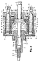
- Figure 4 is a cross-sectional side elevation view of the actuator for the shear ram-type blowout preventer shown in Figure 3 in the closed position;
- Figures 5A and 5B are perspective views of the booster piston cross section and stroke limiting spacer, respectively, of the booster and stroke limiting apparatus of the present invention shown in Figures 3 and 4;
- Figure 6 is a cross-sectional view of the booster piston and stroke limiting spacer assembled into the booster and stroke limiting apparatus of the present invention shown in Figures 5A and 5B;
- Figures 7A, B, and C illustrate the operating piston and the booster and stroke limiting apparatus prior to the shearing and sealing strokes, after the shearing stroke, and then after the sealing stroke, respectively;
- Figure 8 is a cross-sectional side elevation view of the actuator for a pipe ram-type blowout preventer utilizing the boosterand stroke limiting apparatus of the present invention with the top half of Figure 8 showing the open position and the bottom half of Figure 8 showing the closed position; and
- Figures 9A, B and C illustrate the operating piston and booster and stroke limiting apparatus at various positions of the operating piston during the stroke of the pipe ram of Figure 8.
- Referring initially to Figures 1 and 2, there is shown a ram-
type blowout preventer 10 of the shearing type in that it is able to shear that portion of thepipe string 12 positioned within theblowout preventer 10 when an emergency condition arises requiring the shearing of the pipe string and the sealing of the well.Blowout preventer 10 includes a body orhousing 14 with avertical bore 16 extending therethrough.Pipe string 12 passes throughbore 16 and extends downwardly into the wellbore.Housing 14 may include flanges (not shown) so thatblowout preventer 10 may be connected in a wellhead stack. Ram guideways 18, 20 extend transversely outward from opposite sides ofbore 16. First and second shearing rams 22 and 24 are positioned for reciprocation withinguideways - Hydraulic actuation means, such as
actuators rams bore 16 for shearing that portion of thepipe string 12 which extends throughbore 16 and for retractingrams bore 16.Actuators shaft rams rams shafts shaft head 32 which is received in aslot 34 in the radial outer end ofram 22. Thus, ram 22 may be easily disconnected fromshaft 30 by removingram 22 fromguideway 18 and liftingram 22 off of thehead 32 ofshaft 30. - Each of shear rams 22, 24 includes cutting
blades Upper cutting blade 36 is disposed onram 22 andlower cutting blade 38 is disposed onram 24. As shown in Figure 2, the cutting blades are integral with the rams. As is seen in Figure 1, cuttingblades lower blade 38 passes just below the cutting edge ofupper blade 36 in shearing relation to a section of thepipe string 12. - Seal means are also mounted on
rams blades upper blade 36 and side seals 42 on each side oflower blade 38. Side seals 40 are adapted to sealingly engage side seals 42.Rams top seals 23 which extend from side seals 40, 42 across the upper periphery of the rams to sealingly engage the side seals.Blade seal 27 rests belowupper blade 36 and sealingly engages side seals 40, 42 andlower blade 38 when rams 22 and 24 are in the closed position of Figure 2. - Referring now to Figure 3, there is shown the configuration of the actuator of the present invention for the shear
ram blowout preventer 10.Actuator 26, shown in Figure 1, will be described in detail, it being appreciated that the description ofactuator 26 is identical to the description of opposedactuator 28.Actuator 26 includes abonnet 50, acylinder head 52 with a pair ofram change cylinders operating cylinder 58 disposed therebetween.Ram change cylinders cylinder 58 include cylindrical piston bores 62, 64 and 60, respectively. -
Bonnet 50 andcylinder head 52 each include aligned andopposed counterbores ram change cylinders bonnet 50 includes acentral counterbore 74 andcylinder head 52 includes an annular groove orrecess 76 which is aligned and opposed to counterbore 74 so as to receive the respective terminal ends of operatingcylinder 58.Ram change cylinders seal member 78 for sealingly engaging the cylindrical walls formed bycounterbores cylinder 58 forhousing seal members 80, such as o-rings, for sealingly engaging the cylindrical outer walls formed bycentral counterbore 74 andannular recess 76. -
Bonnet 50 further includes acentral bore 82 for slidingly receiving the leading end ofshaft 30. Packing means 84 is disposed incentral bore 82 to sealingly engage the external cylindrical surface ofshaft 30. Anoperating piston 90 is disposed on the outer radial end ofshaft 30 such thatoperating piston 90 is disposed within operatingcylinder 58. A trailingrod 86 is disposed on and extends from the other side ofoperating piston 90 opposite toshaft 30. Trailingrod 86 is slidingly received within amain bore 88 incylinder head 52. Packing seals 92 are provided in an annular recess inmain bore 88 for sealingly engaging the outer cylindrical surface of trailingrod 86. - Referring now to Figure 4, operating
piston 90 is generally circular in cross section and includes a inwardly radial facingannular bearing surface 98 and an outward radial facingannular bearing surface 100. Operatingpiston 90 also includes an inwardly radial facingannular stop shoulder 110adjacent shaft 30 and an outwardly radial facingannular stop shoulder 112 adjacent trailingrod 86. Inwardly facingstop shoulder 110 is adapted to engage thebottom surface 102 ofcentral counterbore 74 in the closed position as shown in Figure 4. Outwardly facingannular stop shoulder 112 is adapted to engage theannular boss 114 formed byannular recess 76 in the open position shown in Figure 3. A pair ofannular flanges annular sealing groove 96 around the outer circumference ofoperating piston 90.Aseal member 97, such as an o-ring, is disposed ingroove 96.Annularflange 104 has a larger diameter thanannular bearing surface 98 thus forming anannular recess 116 and a radially inwardly facingannular stop surface 119. - The trailing
rod 86 extends radially outward ofcylinder head 52 throughbore 88 and is received within alock screw housing 117 which is fastened tocylinder head 52 by fastener means such as bolts and nuts 118.Lock screw housing 117 includes acentral aperture 122 for receiving the terminal end of trailingrod 86.Central aperture 122 includes a threaded reduceddiameter portion 124 for threadingly receiving alock screw 120 havingexternal threads 121.Manual lock screw 120 includes anenlarged diameter head 126 which is disposed withincentral aperture 122. The terminal end ofhead 126 is adapted to abut the terminal end of trailingrod 86. - Referring now to Figures 3-6 and particularly to Figures 5A, 5B and 6, there is shown the booster and
stroke limiting apparatus 130 of the present invention which forms an adapter mounted around the circumference ofoperating piston 90. The booster andstroke limiting apparatus 130 includes astroke limiting spacer 132 and abooster piston 134.Spacer 132 andbooster piston 134 are circular in cross-section and formcylindrical surfaces cylinder 58. -
Stroke limiting spacer 132 is connected tobooster piston 134 by one of several methods. The preferred method is shown in Figures 5A, 5B and 6 wherebooster piston 138 is an annular ring like member having an annular J-slot groove 140 forming a radially extendingannular flange 142.Stroke limiting spacer 132 may comprise a pair of C-shaped members including a radially inwardly facing J-shapedgroove 144 forming an inwardly directedannular flange 146. Upon connection ofbooster piston 138 withstroke limiting spacer 132, inwardly directedannular flange 146 of each C-shaped half ofstroke limiting spacer 132 is received within J-slot groove 140 ofbooster piston 138. Likewise, outwardly directedannular flange 142 ofbooster piston 138 is received in J-slot groove 144 of each of the C-shaped halves ofstroke limiting spacer 132. Such interlocking engagement connectspiston 134 tospacer 132.Stroke limiting spacer 132 includes an externalannular groove 148 for receiving anannular seal member 150, such as an o-ring, which when disposed withingroove 148 holds the two C-shaped halves ofspacer 132 in place aroundannular booster piston 134. Once the booster andstroke limiting apparatus 130 is disposed within the piston bore 60 of operatingcylinder 58, the cylindrical walls ofbore 60 of operatingcylinder 58 maintain the interlocking connection betweenspacer 132 andbooster piston 134.Booster piston 134 includes an annularexternal groove 149 for receiving anannular seal member 151, such as an o-ring. An alternative method of connectingspacer 132 andbooster piston 134 is to provide cap screws which extend throughspacer 132 for threaded engagement in tapped bores inbooster piston 134. - Booster and
stroke limiting apparatus 130 is mounted around the outer circumference ofoperating piston 90.Booster piston 134 includes an inwardly radially directedflange 152 forming a radialannular bearing shoulder 154. Further,stroke limiting spacer 132 includes anannularflange 157 having an inwardly radially facingannular bearing surface 156. As best shown in Figure 3, upon the assembly ofstroke limiting spacer 132 andbooster piston 134 to form boosterandstroke limiting apparatus 130,annular bearing shoulder 154 and inwardly facingannular bearing surface 156 form anannular channel 160 in which is disposedannular flanges operating piston 90. Theseal member 97 disposed inannular groove 96 sealingly engages the innercylindrical wall 162 ofchannel 160. Likewise, the sealingmember 151 inannular groove 149 sealingly engages the cylindrical bore 60 of operatingcylinder 58. - Referring now to Figures 6, 7A, 7B and 7C, the
height 164 betweenannular stop shoulder 110 and the face ofannular flange 104 is greater than thethickness 166 ofannular flange 152 ofbooster piston 138. Further, the thickness 165 of annular flange 159 is less than theheight 167 ofshoulder 112 such thatshoulder 112 is allowed to engageboss 114 beforeflange 106 can engagesurface 156 ofannular flange 157 in the open position shown in Figure 7A. Upon the assembly of booster andstroke limiting apparatus 130 as shown in Figure 6, theradial height 168 betweenshoulder 154 andsurface 156 is the maximum distance of travel ofoperating piston 90 within theannular channel 160. In the closed position as shown in Figure 7C, theoperating piston 90 together with the booster andstroke limiting apparatus 130 moves radially inward withincylinder 58 until the bottom or inwardly facingradial stop surface 155 ofapparatus 130 engages and bottoms out on thebottom surface 102 ofcounterbore 74 as shown in Figure 7B. Uponsurface 155engaging surface 102, the shearing stroke of booster andstroke limiting apparatus 130 is terminated. However, operatingpiston 90 continues its travel and sealing stroke withinannular channel 160 untilannular stop shoulder 110 ofoperating piston 90 engagesbottom surface 102 ofcounterbore 74 as shown in Figure 7C. Operatingpiston 90 thus has a longer stroke than that of booster andstroke limiting apparatus 130 since operatingpiston 90 may continue to travel within operatingcylinder 58 by continued movement withinannular channel 160 even though the booster andstroke limiting apparatus 130 has terminated its shearing stroke by the engagement ofsurfaces - Referring now to Figures 4 and 7, as can be appreciated, upon the hydraulic actuation of
operating piston 90 and booster andstroke limiting apparatus 130, hydraulic pressure is applied across theannular area 169 formed by operatingpiston 90 and booster andstroke limiting apparatus 130. Referring particularly to Figure 6, theannular flange 157 ofstroke limiting spacer 132 has a reduced diameter to allowspacer 132 to have a portion thereof be received withinannular recess 76 thus allowingsurface 112 ofoperating piston 90 to bottom onboss 114. Upon the application of hydraulic pressure to close the shear rams 22, 24, the inwardly facingsurface 156 ofstroke limiting spacer 132 engages theannular bearing surface 100 ofoperating piston 90 such that booster andstroke limiting apparatus 130 andoperating piston 90 move in tandem through the piston bore 60 of operatingcylinder 58 untilstop surface 155 ofbooster piston 134 engagessurface 102 ofcounterbore 74 as shown in Figure 7B. This movement ofoperating piston 90 and booster andstroke limiting apparatus 130 may be called the shearing stroke since thepipe 12 is fully severed by this stroke ofactuator 26 andopposed actuator 28. However, the seals of shear rams 22, 24 have not yet engaged. The further stroke ofoperating piston 90 withinannular channel 160 after the termination of the travel of the booster andstroke limiting apparatus 130 causes shear rams and ram seals to travel within further bore 16 and to sealingly engage and is called the sealing stroke ofactuators operating piston 90 is less than that of the combined areas ofoperating piston 90 and booster andstroke limiting apparatus 130, the pressure force during the sealing stroke is less than the pressure force during the shearing stroke. The pressure area is reduced by theannular area 161 shown in Figure 6 which is the thickness of thecylinder wall 162 ofapparatus 130. - Referring now to Figure 4, to effect the shearing and sealing strokes of
actuators housing 14 of blow-out preventer 10. The hydraulic fluid is provided through ports (not shown) withinhousing 14. A pair ofram change pistons ram change cylinders seals bonnet 50 and further includeseals cylindrical wall ram change pistons housing 14 by threadingly engaging the threaded terrninal ends 178, 180 ofram change pistons housing 14 which are in communication with the hydraulic ports ofhousing 14 and thus the source of hydraulic pressure. - The source of the hydraulic pressure typically includes a set of accumulators (not shown) which provide fluid under pressure, such as at a pressure of approximately 3,000 psi. The accumulators hydraulically communicate with
housing 14 through a regulator (not shown) to regulate the pressure of the fluid being provided toblowout preventer 10. A bypass around the regulator may be provided so as to provide full fluid pressure toblowout preventer 10 if desired. -
Ram change piston 170 receives fluid pressure from the ports ofhousing 14 forthe purpose of actuating rams 22, 24 into the open position shown in Figure 3. The hydraulic fluid passes throughhydraulic bore 174 as shown by the arrow in Figure 4 and passes intoram change cylinder 54 through a transversecross drill port 182 inram change piston 170 and into cylinder bore 62. A hydraulic passageway is provided between cylinder bore 62 and the radialinner chamber 184 of operatingcylinder 58, best shown in Figure 3. This passageway is formed by a drilledbore 186 which is plugged at 188 and an intersectingtransverse bore 190. A like passageway is provided betweeninner chamber 184 and ram change cylinder bore 64 to allow the simultaneous passage of hydraulic fluid intoram change cylinder 56. As operatingpiston 90 and booster andstroke limiting apparatus 130 travel radially outward, the radiallyouter chamber 192 ofcylinder 62, best shown in Figure 4, contracts forcing the hydraulic fluid inouter chamber 192 through a passageway incylinder head 52. This passageway is formed by ahydraulic bore 194 and the transversehydraulic bore 196 which is in fluid communication withram change cylinder 56.Hydraulic bore 196 is also plugged at 198. Thehydraulic bore 176 ofram change piston 172 extends through the axial length ofram change piston 172 and is in fluid communication withhydraulic bore 196. Thus, the hydraulic fluid inouter chamber 192 may be relieved upon the opening of the actuator by the passage of hydraulic fluid throughram change piston 172 and into the hydraulic ports ofhousing 14 to a sump (not shown) connected with the accumulators. - To close
actuators hydraulic bore 176 in the direction of the arrow and through bores 194,196 intoouter chamber 192. Alike passageway is provided betweenouter chamber 192 and ram change cylinder bore 62 to allow the simultaneous passage of hydraulic fluid intoram change cylinder 54. The hydraulic pressure is applied acrossannular area 169. This causes operatingpiston 90 and booster andstroke limiting apparatus 130 to travel through the shearing and sealing strokes as previously described. These strokes contractinner chamber 184 causing the hydraulic fluid to be relieved through bores 190,186, intohydraulic cylinder 54 and throughports ram change piston 170 and intohousing 14 to the sump. Once in the closed position,lock screw 120 may be threaded intoaperture 122 until it engages trailingrod 86 to maintain the closed position even if hydraulic pressure is lost. - As an example, in a seven inch shear-ram type blowout preventer, in excess of 108,000 pounds of force may required to shear
pipe string 12. With the accumulators having hydraulic fluid under 3,000 psi pressure, the hydraulic fluid is directed through the bypass around the regulator so as to provideactuator 26 with approximately 2,800 psi pressure. Although this pressure may approach 3,000 psi, approximately 2,800 psi is all that the operator may be assured of having available in the field. The operatingcylinder 58 has a diameter of 9-1/4 inches such that a 2,800 psi fluid pressure is applied on theannular pressure area 169 ofoperating piston 90 and booster andstroke limiting apparatus 130 providing approximately 180,000 pounds of force to shearpipe string 12. The 180,000 pounds of force is applied to the shearing stroke ofactuator 26 to thereby shear the pipe. To avoid placing this force on the ram seals which increases the stress in the rubber of those seals thereby dramatically decreasing the service life of the seals, the booster andstroke limiting apparatus 130 bottoms out incounterbore 74 such that a reduced pressure force is applied during the sealing stroke.Apparatus 130 bottoms out before the ram seals contact but after the shearing ofpipe string 12. Upon completing the shearing stroke, theoperating piston 90 continues its travel withinannular channel 160 approximately three-quarters of an inch. The sealing stroke of three-quarters of an inch thereby sealingly engages and energizes the ram seals. The reduction of the annular pressure area to only the area ofoperating piston 90 reduces the pressure force to approximately 100,000 pounds force on the ram seals. Thus, the force for sealingly engaging and energizing ram seals is reduced approximately 80,000 pounds thereby decreasing the stress in the rubber and increasing the surface life of the seals. - In assembling
actuator 26, the terminal ends ofram change cylinders counterbores cylinder 58 is inserted intocounterbore 74. Thereafter, ramchange pistons cylinders stroke limiting apparatus 130 is mounted aroundoperating piston 90 and held in place by o-ring 150. That assembly is then slidingly received by piston bore 60 of operatingcylinder 58 withshaft 30 passing throughcentral aperture 82.Cylinder head 52 is then placed over the other terminal ends ofcylinders bores annular grooves 76, respectively. The trailingrod 86 is passed throughcentral aperture 88. As best shown in Figures 2 and 3,tie rods 199 extend frombonnet 50 and through bores incylinder head 52 to fastenhead 52 tobonnet 50. Actuator26 is fastened tohousing 14 bybonnet bolts 197.Lock screw housing 116 and lockscrew 120 are then assembled on top ofcylinder head 52 byfasteners 118. As shown with respect to ramchange operating piston 170, each ram change piston includes a plurality offlats 208 for threading the threaded ends 178, 180 ofram change pistons housing 14 of ram-type blowout preventer 10. In the assembly, thetie bolts 199 draw the respective parts together with the terminal ends of operatingcylinder 58 bottoming out first before the terminal ends ofram change cylinders bores - As can be appreciated by one skilled in the art, ram
change pistons change cylinders actuator 26 away fromhousing 14 for the purpose of changing rams 22. This is accomplished by removingbonnet bolts 197 such that upon the introduction of hydraulic fluid intoram change piston 172 throughbore 176 to close the rams, the hydraulic fluid acts oncylinder head 52 and moves actuator 26 outwardly on ram change pistons 170,172 sincebonnet bolts 197 no longer connectactuator 26 tohousing 14. Further,tie bolts 199 may be removed to removecylinder head 52 and allow for the changing of booster andstroke limiting apparatus 130, reversing its alignment, as hereinafter described in further detail, for use in a pipe ram operator. - This construction of
actuator 26 substantially reduces the weight of the actuator by as much as twenty percent. The prior art actuators include a bonnet which completely encloses the ram change cylinders and also forms a cylindrical skirt around operatingpiston 90. This cylindrical skirt not only adds weight but restricts the size of the operatingcylinder 58 and thus the effective pressure annular area of the operating piston. Thus the construction of the present invention allows for an enhanced pressure area to increase the pressure force to be applied during the operation of the actuator. Previously, such an enhanced pressure force was undesirable because the pressure force was applied not only during the shearing operation but also during the sealing operation. Although the enhanced pressure force was desirable for the shearing operation, it was undesirable during the sealing operation because such an enhanced force was much greater than that required for the sealing operation and tended to substantially shorten the life of the seals on the rams. One of the substantial advantages of the present invention is that the actuator has a shearing stroke with a large pressure force to shear the pipe and a sealing stroke providing a reduced pressure force to seal the rams. - Referring now to Figure 8, there is shown an
actuator 226 adapted for the actuation of pipe rams on a ram-type blowout preventer (not shown) to sealingly engage around a pipe string (not shown) extending through the bore of a blowout preventer. As previously discussed, a pipe ram-type blowout preventer closes opposed rams around the pipe string to sealingly engage the pipe string and close off the bore. One of the principal advantages of the present invention is thatactuator 26 for a shear ram-type blowout preventer may be modified for use asactuator 226 for a pipe ram-type blowout preventer by merely reversing the booster andstroke limiting apparatus 130 within the operating cylinder, as hereinafter described in further detail. This is the only difference between actuator26 andactuator 226 and thus, the numerals utilized in the description ofactuator 26 are also be used in the description ofactuator 226 where such features are the same. - The top portion of Figure 8 illustrates
actuator 226 in the ram open position and the lower half of Figure 8 illustratesactuator 226 in the ram closed position.Actuator 226 includes operatingcylinder 58 disposed betweenbonnet 50 andcylinder head 52. Operatingpiston 90 withshaft 30 and trailingrod 86 are disposed within operatingcylinder 58. - Booster and
stroke limiting apparatus 130 is shown mounted around the outer circumference ofoperating piston 90 but inverted withincylinder 58 such thatstroke limiting spacer 132 is on the radially inward side ofoperating piston 90 andbooster piston 134 is on the radially outward side ofpiston 90. These positions are the reverse ofactuator 26 of shear ram-type blowout preventer 10. - Referring now to Figures 9A, B and C, there is shown the strokes of
actuator 226 to close the pipe rams of the pipe ram-type blowout preventer. As previously described, to close the rams of the blowout preventer, hydraulic fluid under pressure is introduced intohydraulic bore 176 ofram change piston 172. The hydraulic fluid pressure passes intoouter chamber 192 and is applied to theannular pressure area 169 formed by operatingpiston 90 and booster andstroke limiting apparatus 130. As shown in Figure 9A, bearingsurface 154 ofbooster piston 134 engages theupper surface 100 ofoperating piston 90. Operatingpiston 90 and booster andstroke limiting apparatus 130 travel together from the position shown in Figure 9Ato the position shown in Figure 9B where the lowerannular stop surface 210 ofspacer 132 engages thebottom surface 102 ofcounterbore 74. This travel of the combinedoperating piston 90 and booster andstroke limiting apparatus 130 may be called the initial or large sealing stroke which applies a full pressure force onannular area 169 to the stroke of the rams for sealingly engaging the seals of the rams against the pipe string passing through the bore of the pipe ram-type blowout preventer. - As shown in Figure 9C, after the booster and
stroke limiting apparatus 130 bottoms onsurface 102, operatingpiston 90 continues its stroke withinchannel 160. This travel continues untilannular surface area 98 engages thestop surface 156 ofspacer 132. This stroke may be termed the reduced sealing stroke since only the hydraulic pressure on the upper face ofoperating piston 90 provides a pressure force for placing the seals of the rams into final sealing engagement around the pipe string. The length of the travel of the reduced sealing stroke may be measured by the radial height 214 extending betweensurface 100 ofannular flange 106 andsurface 98 subtracted from theradial height 168 ofannular channel 160. The total stroke ofactuator 226 is shorter than the total stroke ofactuator 26 by theradial height 212 ofstroke limiting spacer 132. This is shown in Figure 9C. Thus, thestroke limiting spacer 132 shortens the stroke ofpiston 90 so as to comport with the requirements of a pipe ram-type blowout preventer and also provide the appropriate sealing engagement of the pipe rams around the pipe string. - By way of example, in a seven inch pipe ram-type blowout preventer, the pressurized hydraulic fluid from the accumulators is passed through a regulator to provide a hydraulic pressure of approximately 1,500 psi to the blowout preventer. The 1,500 hydraulic pressure is applied across
annular pressure area 169 thereby providing an actuator force of approximately 95,000 pounds on the pipe rams. This 95,000 pounds of force is applied during the initial sealing stroke ofoperating piston 90 and booster andstroke limiting apparatus 130. Once booster andstroke limiting apparatus 130 bottoms withincounterbore 74, operatingpiston 90 continues to travel withinannular channel 160 approximately 3/8 of an inch. This is the travel of the reduced sealing stroke. Due to the reduction of the annular pressure area during the reduced sealing stroke, there is a force of approximately 60,000 pounds applied by operatingpiston 90 on the pipe rams. The reduction of the force during the initial sealing stroke and reduced sealing stroke is not critical to the effective sealing engagement of the pipe ram seals so as to seal around the pipe string and seal off the bore. Thestroke limiting spacer 132 reduces the overall sealing stroke by approximately 7/8ths of an inch. - The present invention avoids dedicated blowout preventers for use either with shear rams or pipe rams since the present invention allows the easy interchangeability of the actuator for use with either shear or pipe rams. As can be seen, the adaptation of
actuator 26 for shear rams to that ofactuator 226 for pipe rams requires no additional parts nor the replacement of any existing parts. All that is required is the reversal of the booster andstroke limiting apparatus 130 to appropriately limit the stroke to meet the requirements of a pipe ram-type blowout preventer. It can also be seen that a minimum disassembly and re-assembly is required to modify the actuator of the present invention for use either with shear rams or pipe rams. This not only saves the expense of additional or new parts but also reduces the time in the field for modification of the actuator. - The configuration of the actuator of the present invention, although having the same basic function, is constructed in a different manner to reduce weight and to allow for an increased
annular pressure area 169. In the prior art, the bonnet includes a cylindrical skirt which extends around the operating cylinder between the operating cylinder and the ram change cylinders. The disposal of the skirt between the cylinders limits the diameter of the operating cylinder. The present invention has eliminated the cylindrical skirt of the prior art so as to allow an increased diameter for operatingcylinder 58 and thus an increasedannular pressure area 169. For example, in the prior art, a seven inch blowout prevent utilized a 7-1/4 inch diameter operating cylinder and operating piston. In the present invention, in a seven inch blowout preventer, actuators 26, 226 include an operating cylinder having a 9-1/4 inch diameter to receive a 7-1/4inch operating piston 90, the same size as the prior art piston, but also includes the booster andstroke limiting apparatus 130 such that the overall annular pressure area ofoperating piston 90 and booster andstroke limiting apparatus 130 is 9-1/4 inches.
Claims (9)
Applications Claiming Priority (2)
| Application Number | Priority Date | Filing Date | Title |
|---|---|---|---|
| US22970094A | 1994-04-19 | 1994-04-19 | |
| US229700 | 1994-04-19 |
Publications (3)
| Publication Number | Publication Date |
|---|---|
| EP0678656A2 true EP0678656A2 (en) | 1995-10-25 |
| EP0678656A3 EP0678656A3 (en) | 1996-09-25 |
| EP0678656B1 EP0678656B1 (en) | 1998-11-25 |
Family
ID=22862359
Family Applications (1)
| Application Number | Title | Priority Date | Filing Date |
|---|---|---|---|
| EP95301917A Expired - Lifetime EP0678656B1 (en) | 1994-04-19 | 1995-03-22 | Ram-type blowout preventor |
Country Status (4)
| Country | Link |
|---|---|
| US (1) | US5653418A (en) |
| EP (1) | EP0678656B1 (en) |
| CA (1) | CA2145145A1 (en) |
| DE (1) | DE69506161T2 (en) |
Cited By (1)
| Publication number | Priority date | Publication date | Assignee | Title |
|---|---|---|---|---|
| CN114396241A (en) * | 2022-03-28 | 2022-04-26 | 四川新为橡塑有限公司 | Double-layer sealed spherical rubber core and annular blowout preventer |
Families Citing this family (27)
| Publication number | Priority date | Publication date | Assignee | Title |
|---|---|---|---|---|
| WO2002018727A1 (en) * | 2000-08-28 | 2002-03-07 | Global Marine Inc. | Work platform for blowout preventer stacks |
| DE20018561U1 (en) * | 2000-10-30 | 2002-03-21 | Cameron Gmbh | Blowout valve arrangement |
| US6554247B2 (en) * | 2001-05-04 | 2003-04-29 | Hydril Company | Quick release blowout preventer bonnet |
| US6719262B2 (en) | 2001-08-06 | 2004-04-13 | Cooper Cameron Corporation | Bidirectional sealing blowout preventer |
| US6843463B1 (en) * | 2002-08-30 | 2005-01-18 | Varco I/P/ Inc. | Pressure regulated slip ram on a coil tubing blowout preventer |
| US6969042B2 (en) * | 2004-05-01 | 2005-11-29 | Varco I/P, Inc. | Blowout preventer and ram actuator |
| US7195224B2 (en) * | 2005-02-01 | 2007-03-27 | Varco I/P, Inc. | Blowout preventer and locking mechanism |
| US20080105436A1 (en) * | 2006-11-02 | 2008-05-08 | Schlumberger Technology Corporation | Cutter Assembly |
| US7798466B2 (en) | 2007-04-27 | 2010-09-21 | Varco I/P, Inc. | Ram locking blowout preventer |
| US8132777B2 (en) * | 2008-01-23 | 2012-03-13 | Alberta Petroleum Industries Ltd. | Blowout preventer having modified hydraulic operator |
| US9109421B2 (en) * | 2008-12-18 | 2015-08-18 | Hydril USA Distribution LLC | Deformation resistant opening chamber head and method |
| US8844898B2 (en) | 2009-03-31 | 2014-09-30 | National Oilwell Varco, L.P. | Blowout preventer with ram socketing |
| US8225879B2 (en) * | 2009-11-25 | 2012-07-24 | Hydril Usa Manufacturing Llc | Ram blowout preventer stroke limiting and method |
| US8544538B2 (en) | 2010-07-19 | 2013-10-01 | National Oilwell Varco, L.P. | System and method for sealing a wellbore |
| US8540017B2 (en) | 2010-07-19 | 2013-09-24 | National Oilwell Varco, L.P. | Method and system for sealing a wellbore |
| KR101697397B1 (en) | 2011-03-09 | 2017-01-17 | 내셔널 오일웰 바르코 엘.피. | Method and apparatus for sealing a wellbore |
| CN104145077B (en) * | 2011-10-19 | 2016-12-14 | 卡梅伦国际有限公司 | Depressurized system under water |
| US9359851B2 (en) * | 2012-02-23 | 2016-06-07 | Bastion Technologies, Inc. | High energy tubular shear |
| GB2514937B (en) * | 2012-04-02 | 2019-02-27 | Halliburton Energy Services Inc | Method for pressure-actuated tool disconnection |
| EP2836669B1 (en) | 2012-04-10 | 2019-07-24 | National Oilwell Varco, L.P. | Blowout preventer with locking ram assembly and method of using same |
| CN104285030B (en) | 2012-04-10 | 2017-07-07 | 国民油井华高公司 | Blowout prevention locks door component and its application method |
| WO2015017662A1 (en) * | 2013-08-01 | 2015-02-05 | Bop Technologies, Inc. | Intensifier ram blowout preventer |
| US10190382B2 (en) * | 2015-10-20 | 2019-01-29 | Worldwide Oilfield Machine, Inc. | BOP booster piston assembly and method |
| DK3400366T3 (en) * | 2016-01-05 | 2020-09-28 | Noble Drilling Services Inc | PRESSURE ASSISTED MOTOR DRIVE PISTON ACTUATOR FOR WELL PRESSURE CONTROL DEVICE |
| US10378301B2 (en) | 2017-05-31 | 2019-08-13 | Worldwide Oilfield Machine, Inc. | BOP compact bonnet-booster (CBB) piston assembly and method |
| NO344201B1 (en) * | 2017-10-17 | 2019-10-14 | Electrical Subsea & Drilling As | Electro mechanical power actuator |
| WO2023224852A1 (en) * | 2022-05-14 | 2023-11-23 | Kinetic Pressure Control, Ltd. | Systems and methods for fluid pressure control |
Citations (7)
| Publication number | Priority date | Publication date | Assignee | Title |
|---|---|---|---|---|
| US3018762A (en) * | 1960-05-02 | 1962-01-30 | Permanent Mold Die Co Inc | Double piston arrangement |
| US3946806A (en) * | 1972-06-16 | 1976-03-30 | Cameron Iron Works, Inc. | Ram-type blowout preventer |
| US4349041A (en) * | 1979-08-20 | 1982-09-14 | Nl Industries, Inc. | Control valve system for blowout preventers |
| US4448254A (en) * | 1982-03-04 | 1984-05-15 | Halliburton Company | Tester valve with silicone liquid spring |
| GB2131470A (en) * | 1982-12-02 | 1984-06-20 | Koomey Blowout Preventers Inc | Blowout preventer |
| US4699350A (en) * | 1985-04-04 | 1987-10-13 | TOTAL Compagnie Francaise de Petroles | Valve and a process for removing a closure member of the valve |
| EP0468788A1 (en) * | 1990-07-26 | 1992-01-29 | John J. Wright | Hydraulic booster device for linear actuator |
Family Cites Families (10)
| Publication number | Priority date | Publication date | Assignee | Title |
|---|---|---|---|---|
| US2649842A (en) * | 1947-05-16 | 1953-08-25 | Electro Hydraulics Ltd | Fluid pressure motor comprising relatively extensible and contractible piston and cylinder elements |
| US4043389A (en) * | 1976-03-29 | 1977-08-23 | Continental Oil Company | Ram-shear and slip device for well pipe |
| US4132267A (en) * | 1978-04-06 | 1979-01-02 | Cameron Iron Works, Inc. | Pipe shearing ram assembly for blowout preventer |
| US4249458A (en) * | 1979-05-11 | 1981-02-10 | The Bendix Corporation | Piston and extensible cylinder therefor |
| US4313496A (en) * | 1980-04-22 | 1982-02-02 | Cameron Iron Works, Inc. | Wellhead shearing apparatus |
| US4492359A (en) * | 1982-06-25 | 1985-01-08 | Baugh Benton F | Valve assembly |
| SE450517B (en) * | 1982-09-23 | 1987-06-29 | Volvo Ab | CYLINDER WITH TWICE STEP MORAL |
| US4504037A (en) * | 1983-09-26 | 1985-03-12 | Hydril Company | Ram blowout preventer securing and retracting apparatus |
| US5067323A (en) * | 1990-06-13 | 1991-11-26 | United Technologies Corporation | Three position actuator arrangement |
| US5294088A (en) * | 1992-10-13 | 1994-03-15 | Cooper Industries, Inc. | Variable bore packer for a ram-type blowout preventer |
-
1995
- 1995-03-21 CA CA002145145A patent/CA2145145A1/en not_active Abandoned
- 1995-03-22 DE DE69506161T patent/DE69506161T2/en not_active Expired - Fee Related
- 1995-03-22 EP EP95301917A patent/EP0678656B1/en not_active Expired - Lifetime
-
1996
- 1996-01-05 US US08/583,561 patent/US5653418A/en not_active Expired - Lifetime
Patent Citations (7)
| Publication number | Priority date | Publication date | Assignee | Title |
|---|---|---|---|---|
| US3018762A (en) * | 1960-05-02 | 1962-01-30 | Permanent Mold Die Co Inc | Double piston arrangement |
| US3946806A (en) * | 1972-06-16 | 1976-03-30 | Cameron Iron Works, Inc. | Ram-type blowout preventer |
| US4349041A (en) * | 1979-08-20 | 1982-09-14 | Nl Industries, Inc. | Control valve system for blowout preventers |
| US4448254A (en) * | 1982-03-04 | 1984-05-15 | Halliburton Company | Tester valve with silicone liquid spring |
| GB2131470A (en) * | 1982-12-02 | 1984-06-20 | Koomey Blowout Preventers Inc | Blowout preventer |
| US4699350A (en) * | 1985-04-04 | 1987-10-13 | TOTAL Compagnie Francaise de Petroles | Valve and a process for removing a closure member of the valve |
| EP0468788A1 (en) * | 1990-07-26 | 1992-01-29 | John J. Wright | Hydraulic booster device for linear actuator |
Cited By (2)
| Publication number | Priority date | Publication date | Assignee | Title |
|---|---|---|---|---|
| CN114396241A (en) * | 2022-03-28 | 2022-04-26 | 四川新为橡塑有限公司 | Double-layer sealed spherical rubber core and annular blowout preventer |
| CN114396241B (en) * | 2022-03-28 | 2022-06-10 | 四川新为橡塑有限公司 | Double-layer sealed spherical rubber core and annular blowout preventer |
Also Published As
| Publication number | Publication date |
|---|---|
| EP0678656A3 (en) | 1996-09-25 |
| DE69506161T2 (en) | 1999-04-15 |
| CA2145145A1 (en) | 1995-10-20 |
| US5653418A (en) | 1997-08-05 |
| DE69506161D1 (en) | 1999-01-07 |
| EP0678656B1 (en) | 1998-11-25 |
Similar Documents
| Publication | Publication Date | Title |
|---|---|---|
| US5653418A (en) | Ram-type blowout preventer | |
| US4437643A (en) | Ram-type blowout preventer | |
| US11187054B2 (en) | BOP booster piston assembly and method | |
| US6158505A (en) | Blade seal for a shearing blind ram in a ram type blowout preventer | |
| US6367804B1 (en) | Variable bore ram packer for tapered tubular members in a ram type blowout preventer | |
| US6244560B1 (en) | Blowout preventer ram actuating mechanism | |
| CN111764859B (en) | Wellbore control apparatus, connection device and method | |
| CA1294599C (en) | Modular hydraulic actuator | |
| US5590867A (en) | Blowout preventer for coiled tubing | |
| EP0902161B1 (en) | Improved variable bore ram packer for a ram type blowout preventer | |
| US20060038147A1 (en) | Unitary blade seal for a shearing blind ram in a ram type blowout preventer | |
| US10570690B2 (en) | BOP compact bonnet-booster (CBB) piston assembly and method | |
| US20040021269A1 (en) | Compact insert for variable bore ram packer in a ram type blowout preventer | |
| WO2017039951A1 (en) | Blowout Preventer with Pipe Ram Packer Assemblies with Support Tab | |
| WO2017040198A1 (en) | Blowout Preventer with Shear Ram | |
| US10202817B2 (en) | Packer assembly with inserts for blowout preventer | |
| US9976374B2 (en) | Side packer assembly with support member for ram blowout preventer | |
| US4044988A (en) | Blowout ram preventer | |
| US20190145217A1 (en) | Blowout preventer bonnet assembly | |
| RU2088745C1 (en) | Device for wellhead sealing, unit of seals and unit of stop slips | |
| SU1148970A1 (en) | Blowout preventer | |
| NO342003B1 (en) | Blow out preventer bonnet assembly | |
| MXPA00008452A (en) | Blade seal for a shearing blind ram in a ram type blowout preventer |
Legal Events
| Date | Code | Title | Description |
|---|---|---|---|
| PUAI | Public reference made under article 153(3) epc to a published international application that has entered the european phase |
Free format text: ORIGINAL CODE: 0009012 |
|
| AK | Designated contracting states |
Kind code of ref document: A2 Designated state(s): DE FR GB |
|
| PUAL | Search report despatched |
Free format text: ORIGINAL CODE: 0009013 |
|
| AK | Designated contracting states |
Kind code of ref document: A3 Designated state(s): DE FR GB |
|
| 17P | Request for examination filed |
Effective date: 19970314 |
|
| 17Q | First examination report despatched |
Effective date: 19970701 |
|
| GRAG | Despatch of communication of intention to grant |
Free format text: ORIGINAL CODE: EPIDOS AGRA |
|
| GRAG | Despatch of communication of intention to grant |
Free format text: ORIGINAL CODE: EPIDOS AGRA |
|
| GRAH | Despatch of communication of intention to grant a patent |
Free format text: ORIGINAL CODE: EPIDOS IGRA |
|
| GRAH | Despatch of communication of intention to grant a patent |
Free format text: ORIGINAL CODE: EPIDOS IGRA |
|
| GRAA | (expected) grant |
Free format text: ORIGINAL CODE: 0009210 |
|
| AK | Designated contracting states |
Kind code of ref document: B1 Designated state(s): DE FR GB |
|
| REF | Corresponds to: |
Ref document number: 69506161 Country of ref document: DE Date of ref document: 19990107 |
|
| ET | Fr: translation filed | ||
| PLBE | No opposition filed within time limit |
Free format text: ORIGINAL CODE: 0009261 |
|
| STAA | Information on the status of an ep patent application or granted ep patent |
Free format text: STATUS: NO OPPOSITION FILED WITHIN TIME LIMIT |
|
| 26N | No opposition filed | ||
| REG | Reference to a national code |
Ref country code: GB Ref legal event code: IF02 |
|
| PGFP | Annual fee paid to national office [announced via postgrant information from national office to epo] |
Ref country code: FR Payment date: 20030303 Year of fee payment: 9 |
|
| PGFP | Annual fee paid to national office [announced via postgrant information from national office to epo] |
Ref country code: DE Payment date: 20030331 Year of fee payment: 9 |
|
| PG25 | Lapsed in a contracting state [announced via postgrant information from national office to epo] |
Ref country code: DE Free format text: LAPSE BECAUSE OF NON-PAYMENT OF DUE FEES Effective date: 20041001 |
|
| PG25 | Lapsed in a contracting state [announced via postgrant information from national office to epo] |
Ref country code: FR Free format text: LAPSE BECAUSE OF NON-PAYMENT OF DUE FEES Effective date: 20041130 |
|
| REG | Reference to a national code |
Ref country code: FR Ref legal event code: ST |
|
| PGFP | Annual fee paid to national office [announced via postgrant information from national office to epo] |
Ref country code: GB Payment date: 20140225 Year of fee payment: 20 |
|
| REG | Reference to a national code |
Ref country code: GB Ref legal event code: PE20 Expiry date: 20150321 |
|
| PG25 | Lapsed in a contracting state [announced via postgrant information from national office to epo] |
Ref country code: GB Free format text: LAPSE BECAUSE OF EXPIRATION OF PROTECTION Effective date: 20150321 |