EP0678345B1 - Apparatus for producing Langmuir-Blodgett film - Google Patents
Apparatus for producing Langmuir-Blodgett film Download PDFInfo
- Publication number
- EP0678345B1 EP0678345B1 EP95302632A EP95302632A EP0678345B1 EP 0678345 B1 EP0678345 B1 EP 0678345B1 EP 95302632 A EP95302632 A EP 95302632A EP 95302632 A EP95302632 A EP 95302632A EP 0678345 B1 EP0678345 B1 EP 0678345B1
- Authority
- EP
- European Patent Office
- Prior art keywords
- region
- film
- liquid
- monomolecular
- spreading
- Prior art date
- Legal status (The legal status is an assumption and is not a legal conclusion. Google has not performed a legal analysis and makes no representation as to the accuracy of the status listed.)
- Expired - Lifetime
Links
- 239000000463 material Substances 0.000 claims description 56
- 239000007788 liquid Substances 0.000 claims description 50
- 239000008186 active pharmaceutical agent Substances 0.000 claims description 28
- 239000000758 substrate Substances 0.000 claims description 26
- 238000000034 method Methods 0.000 claims description 18
- 230000007480 spreading Effects 0.000 claims description 15
- 238000003892 spreading Methods 0.000 claims description 15
- 230000006835 compression Effects 0.000 claims description 14
- 238000007906 compression Methods 0.000 claims description 14
- 230000008569 process Effects 0.000 claims description 11
- 230000001105 regulatory effect Effects 0.000 claims description 11
- UKMSUNONTOPOIO-UHFFFAOYSA-N docosanoic acid Chemical compound CCCCCCCCCCCCCCCCCCCCCC(O)=O UKMSUNONTOPOIO-UHFFFAOYSA-N 0.000 claims description 10
- 230000008021 deposition Effects 0.000 claims description 9
- XUIMIQQOPSSXEZ-UHFFFAOYSA-N Silicon Chemical compound [Si] XUIMIQQOPSSXEZ-UHFFFAOYSA-N 0.000 claims description 8
- 229910052710 silicon Inorganic materials 0.000 claims description 8
- 239000010703 silicon Substances 0.000 claims description 8
- 229920000205 poly(isobutyl methacrylate) Polymers 0.000 claims description 7
- 239000002904 solvent Substances 0.000 claims description 6
- 230000004044 response Effects 0.000 claims description 5
- 235000021357 Behenic acid Nutrition 0.000 claims description 4
- 229940116226 behenic acid Drugs 0.000 claims description 4
- KFEVDPWXEVUUMW-UHFFFAOYSA-N docosanoic acid Natural products CCCCCCCCCCCCCCCCCCCCCC(=O)OCCC1=CC=C(O)C=C1 KFEVDPWXEVUUMW-UHFFFAOYSA-N 0.000 claims description 4
- POULHZVOKOAJMA-UHFFFAOYSA-N methyl undecanoic acid Natural products CCCCCCCCCCCC(O)=O POULHZVOKOAJMA-UHFFFAOYSA-N 0.000 claims description 4
- 229920005575 poly(amic acid) Polymers 0.000 claims description 4
- YGTSVJQQDISEHZ-UHFFFAOYSA-N 22-tricosenoic acid Chemical compound OC(=O)CCCCCCCCCCCCCCCCCCCCC=C YGTSVJQQDISEHZ-UHFFFAOYSA-N 0.000 claims description 3
- 235000014113 dietary fatty acids Nutrition 0.000 claims description 3
- 229930195729 fatty acid Natural products 0.000 claims description 3
- 239000000194 fatty acid Substances 0.000 claims description 3
- 150000004665 fatty acids Chemical class 0.000 claims description 3
- 239000011521 glass Substances 0.000 claims description 3
- 239000004626 polylactic acid Substances 0.000 claims description 3
- 239000010445 mica Substances 0.000 claims description 2
- 229910052618 mica group Inorganic materials 0.000 claims description 2
- 239000004417 polycarbonate Substances 0.000 claims description 2
- 229920000515 polycarbonate Polymers 0.000 claims description 2
- 229920000642 polymer Polymers 0.000 claims description 2
- 230000001276 controlling effect Effects 0.000 claims 1
- XLYOFNOQVPJJNP-UHFFFAOYSA-N water Substances O XLYOFNOQVPJJNP-UHFFFAOYSA-N 0.000 description 63
- 239000012071 phase Substances 0.000 description 13
- 230000004888 barrier function Effects 0.000 description 8
- 238000000151 deposition Methods 0.000 description 8
- 230000008859 change Effects 0.000 description 7
- 239000007791 liquid phase Substances 0.000 description 5
- 230000003287 optical effect Effects 0.000 description 4
- 230000033228 biological regulation Effects 0.000 description 3
- 238000004519 manufacturing process Methods 0.000 description 3
- 230000010355 oscillation Effects 0.000 description 3
- 238000011144 upstream manufacturing Methods 0.000 description 3
- HEDRZPFGACZZDS-UHFFFAOYSA-N Chloroform Chemical compound ClC(Cl)Cl HEDRZPFGACZZDS-UHFFFAOYSA-N 0.000 description 2
- 238000004140 cleaning Methods 0.000 description 2
- 238000013016 damping Methods 0.000 description 2
- 230000003993 interaction Effects 0.000 description 2
- 230000002265 prevention Effects 0.000 description 2
- 239000007787 solid Substances 0.000 description 2
- 239000004642 Polyimide Substances 0.000 description 1
- 238000010923 batch production Methods 0.000 description 1
- 230000007423 decrease Effects 0.000 description 1
- 230000000694 effects Effects 0.000 description 1
- 238000002474 experimental method Methods 0.000 description 1
- 238000005442 molecular electronic Methods 0.000 description 1
- 239000011368 organic material Substances 0.000 description 1
- 239000003960 organic solvent Substances 0.000 description 1
- 239000004033 plastic Substances 0.000 description 1
- 229920003023 plastic Polymers 0.000 description 1
- 229920000747 poly(lactic acid) Polymers 0.000 description 1
- 229920001721 polyimide Polymers 0.000 description 1
- 239000002243 precursor Substances 0.000 description 1
- 239000004065 semiconductor Substances 0.000 description 1
- 239000000126 substance Substances 0.000 description 1
- 238000010408 sweeping Methods 0.000 description 1
- 230000032258 transport Effects 0.000 description 1
- 239000002699 waste material Substances 0.000 description 1
Images

Classifications
-
- B—PERFORMING OPERATIONS; TRANSPORTING
- B05—SPRAYING OR ATOMISING IN GENERAL; APPLYING FLUENT MATERIALS TO SURFACES, IN GENERAL
- B05D—PROCESSES FOR APPLYING FLUENT MATERIALS TO SURFACES, IN GENERAL
- B05D1/00—Processes for applying liquids or other fluent materials
- B05D1/18—Processes for applying liquids or other fluent materials performed by dipping
- B05D1/20—Processes for applying liquids or other fluent materials performed by dipping substances to be applied floating on a fluid
- B05D1/202—Langmuir Blodgett films (LB films)
- B05D1/206—LB troughs
-
- B—PERFORMING OPERATIONS; TRANSPORTING
- B82—NANOTECHNOLOGY
- B82Y—SPECIFIC USES OR APPLICATIONS OF NANOSTRUCTURES; MEASUREMENT OR ANALYSIS OF NANOSTRUCTURES; MANUFACTURE OR TREATMENT OF NANOSTRUCTURES
- B82Y30/00—Nanotechnology for materials or surface science, e.g. nanocomposites
-
- B—PERFORMING OPERATIONS; TRANSPORTING
- B82—NANOTECHNOLOGY
- B82Y—SPECIFIC USES OR APPLICATIONS OF NANOSTRUCTURES; MEASUREMENT OR ANALYSIS OF NANOSTRUCTURES; MANUFACTURE OR TREATMENT OF NANOSTRUCTURES
- B82Y40/00—Manufacture or treatment of nanostructures
Definitions
- a solution 14 containing a material of which the LB film consists is dropped from a nozzle 19, onto the surface of a flow of pure water.
- the material spreads out on the water phase 13.
- the molecules of the LB film forming material are represented by the reference numeral 11.
- the spread LB film forming material is transferred in the water flow to the region C while the solvent of the solution 14 evaporates.
- the LB film-forming material becomes compressed in the region C and a monomolecular film 12 in which the molecules 11 are brought into an orientation is formed on the water surface in the regions C and D.
- a stable flow is necessary to compress the material uniformly. Therefore the channel in the region C has a slope so that the water surface has a slight descent toward the region D.
- the tank is preferably formed so that the water phase in the region C is thin. As a result, the water flow becomes laminar.
- the water phase in the region S must have adequate depth in order to prevent the water flow from being influenced by flow variations in this region.
- the depth of the water phase in the region D is preferably greater than that in region C in order to permit the substrate 15 to be immersed and to accommodate fluctuation in the amount of water which is drained.
- the effective thickness of the water flow in the region C changes at the border between where the surface is not covered and where the surface is covered with the monomolecular film, and also when the end position of the monomolecular film changes, the total amount of the water in the region C changes.
- the water levels in the region S and in the region D change according to the change of the area of the water surface which the monomolecular film covers, i.e. depending on change of the end position of the monomolecular film.
- the change of the water level in the region D causes the effective length of the region C, which influences the compression of the material, and the length of the slope in the region C to be changed, which gives rise to a change in the surface pressure of the monomolecular film in the region C.
- fluctuation of the water level in the region S causes the thickness of the water phase which is not covered with the monomolecular film to vary, and this variation causes the compression of the material to be inhomogeneous.
- the inventors have found experimentally that the prevention of backflow of the material toward the spreading region S suppresses the fluctuations of the surface pressure and the fluctuation of the water level.
- the reason why the fluctuations are suppressed is not clear, but the explanation is believed to be as follows.
- the quality of the monomolecular film formed on the liquid surface is improved by the prevention of the backflow.
- this fluctuation does not cause rapid fluctuation of the surface pressure so that the interaction between the control loop for regulating the surface pressure of the monomolecular film and the control loop for regulating the liquid level of the monomolecular film in the compression region decreases and then a homogenous LB film can be stably obtained.
- the decoupling region effectively prevents backflow.
Landscapes
- Engineering & Computer Science (AREA)
- Chemical & Material Sciences (AREA)
- Nanotechnology (AREA)
- Crystallography & Structural Chemistry (AREA)
- Condensed Matter Physics & Semiconductors (AREA)
- General Physics & Mathematics (AREA)
- Physics & Mathematics (AREA)
- Materials Engineering (AREA)
- Composite Materials (AREA)
- Manufacturing & Machinery (AREA)
- Coating Apparatus (AREA)
- Application Of Or Painting With Fluid Materials (AREA)
- Non-Silver Salt Photosensitive Materials And Non-Silver Salt Photography (AREA)
- Physical Or Chemical Processes And Apparatus (AREA)
Description
- This invention relates to an apparatus for producing Langmuir-Blodgett film (LB film) continuously.
- LB film is an organic film comprising a monomolecular film or multilayer film in which a plurality of monomolecular layers of same or different kinds of organic material are laminated. The thickness of each monomolecular film depends on the length of the molecules of which the LB film consists. "LB films" were discovered by Irving Langmuir and Katherine Blodgett and are generally produced in accordance with the following procedure. A material to form the film is dissolved in a suitable solvent. Then a small amount of the solution is allowed to spread over a clean surface of a liquid, in particular, over a surface of pure water, and then the solvent is allowed to evaporate or disperse into the liquid phase. As a result a loosely packed film of the molecules forms on the liquid surface. The surface is then swept by means of a barrier wall to reduce the area of the loosely packed film mechanically, compress the film and increase its density to give a tightly packed monomolecular film. Next, a solid substrate is immersed in the liquid and then raised e.g. vertically through the monomolecular film on the liquid surface while maintaining the surface density of the molecules of which the monomolecular film consists. Under these conditions the monomolecular film becomes transferred to the substrate and deposited as a monomolecular film on the substrate. By repeated immersing and raising of the substrate, multilayer monomolecular films, that is an LB film, having an integer times thickness of that of the monomolecular film, can be formed on the substrate.
- The surface density of the monomolecular film on the liquid surface can be monitored by measuring a surface pressure, that is the difference between the surface tension of the liquid and the surface tension of the area which is covered with the monomolecular film.
- In the process of film deposition it is important for almost all LB film forming materials to maintain the surface pressure of the monomolecular film within a narrow range. The reason why regulation is important is that the orientation of the molecules in the monomolecular film changes according to the surface pressure. That is to say, where the surface pressure is changed while the LB film is being formed, the orientation in the film is disturbed, and if the orientation is highly disturbed, an LB film might not be produced. The range of tolerance or fluctuation of the surface pressure depends on the material for the LB film and/or the surface pressure for producing the LB film, but it is usual for the surface pressure, to have to be maintained within 1mN/m. Adjustment of the surface pressure is usually by sweeping the barrier wall over the surface to enhance or reduce the area of the liquid surface over which the LB film forming molecules are spread as described above. Therefore in order to maintain the surface pressure within a given range it is necessary to control the position of the barrier wall in response to the surface pressure.
- However, where because of the rapidity of the deposition or the rigidity of the monomolecular film, the change in position of the barrier wall or the response of the film is too slow compared with changes in the measured surface pressure, feedback control may not operate correctly and the surface pressure may oscillate and consequently the position of the barrier wall may oscillate. For example ± 3 mN/m of oscillation may occur. Where the amplitude of oscillation is larger than the above value, the instability in surface pressure means that an LB film is not formed. In particular, if the surface pressure attains a high positive value, the monomolecular film on the liquid surface irreversibly collapses, so that such fluctuations must be restricted.
- Hitherto, the LB films have been produced and film deposition and other procedures have been carried out using film balance apparatus comprising a water tank containing the liquid phase, a barrier wall, a surface pressure gauge and an apparatus for immersing and raising a substrate to be coated or re-coated with an LB film. Now, the quantity of the monomolecular film on the liquid surface, the area of the monomolecular film, depends on the size of the water tank. The area cannot be larger than the surface area of the liquid phase, and actually the monomolecular film is compressed by the barrier wall so that its area is usually smaller than the surface area of the liquid phase. Thus, the total area of the LB film which can be formed on the substrate in a single operation is the same as or less than the area of the monomolecular film which is originally formed on the liquid surface.
- Where it is required to produce on a substrate an LB film having a larger area than the area of the monomolecular film formed on the liquid surface, the following procedure is required. Firstly any residual monomolecular film on the liquid surface is removed to give a clean surface. Examples where this cleaning operation is required is where there remains present a monomolecular film in insufficient quantity to form a film on the intended substrate in a single operation of immersing and raising the substrate, or where the residual monomolecular film is present in parts which cannot be compressed or controlled by movement of the barrier wall due to apparatus restrictions. Next, the LB film forming material is spread on the liquid surface, and then the molecules of the film forming substance which are present on the liquid surface are compressed to form a monomolecular film which can be used to make the LB films. However, the above described LB film producing process is a batch process so that it is not suitable for mass production.
- Various methods have been put forward to meet the need to be able to mass produce LB films. Examples of such disclosures include US Patent No 4,783,348 (O. Albrecht et al), an article by O. Albrecht et al, "Industrial Scale Production of LB-Layers", Molecular Electronics, Biosensors and Biocomputers, edited by F.T. Hong, Plenum Press, NY 1989, pages 41-49, and an article by W. Nitsch et al, "Convective Compression in Channel Flow: Behaviour and Transfer of Soluble and Insoluble Films" Thin Solid Films, Vol. 178, 1989, pages 145-155.
- Now an apparatus and process proposed by O. Albrecht et al for producing the LB film continuously will be explained with reference to Figure 2. The apparatus shown in Figure 2 comprises a
channel 20 having three parts, a spreading region (S), a compression region (C) and a depositing region (D). Pure water flows from the region S to the region D through the region C. - Firstly in the region S, a
solution 14 containing a material of which the LB film consists is dropped from anozzle 19, onto the surface of a flow of pure water. The material spreads out on thewater phase 13. In Figure 2 the molecules of the LB film forming material are represented by thereference numeral 11. Then the spread LB film forming material is transferred in the water flow to the region C while the solvent of thesolution 14 evaporates. The LB film-forming material becomes compressed in the region C and amonomolecular film 12 in which themolecules 11 are brought into an orientation is formed on the water surface in the regions C and D. In the region C, a stable flow is necessary to compress the material uniformly. Therefore the channel in the region C has a slope so that the water surface has a slight descent toward the region D. - In the region D, a
substrate 15 is repeatedly immersed into the water phase and then raised by transferring means (16) which moves the substrate in the perpendicular direction (17) to the liquid surface. Therefore themonomolecular film 12 is deposited continuously on thesubstrate 15 to obtain an LB film. - In the process and the apparatus described above, where some material has already been provided to the water phase and some monomolecular film has already been formed in the region C and the region D, fresh material (solution) from the nozzle (19) is transported to the right as viewed in Figure 2 until the fresh material is stopped by abutment with the end of the already formed monomolecular layer on the liquid surface in the region C. Therefore the new monomolecular layer grows in a direction opposite to the water flow i.e. in an upstream direction. Then, friction which occurs between the new monomolecular film and the water phase gives rise to additional surface pressure contributed by the new monomolecular film so that the surface pressure of the monomolecular film is increased. The surface pressure of the monomolecular film in the region D depends on the form of the container (hereinafter called "water tank") which retains the water phase and the material on the water phase, the water level and the strength of the water flow etc.
- As described above, stable water flow is necessary in the region C. To cope with this requirement, the tank is preferably formed so that the water phase in the region C is thin. As a result, the water flow becomes laminar. However, the water phase in the region S must have adequate depth in order to prevent the water flow from being influenced by flow variations in this region. Furthermore, the depth of the water phase in the region D is preferably greater than that in region C in order to permit the
substrate 15 to be immersed and to accommodate fluctuation in the amount of water which is drained. - The apparatus shown in Figure 2 is provided with a region into which water is flowed, a region from which water is drained, a pump for maintaining the water flow, a level sensor in the region D and means for exchanging the water phase and for removing waste film, and these are not shown in Figure 2.
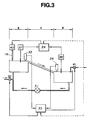
- When the monomolecular film is formed on the water surface by using the apparatus described above, two feedback control loops are preferably operated as the water is caused to flow at an experimentally determined speed. One control loop regulates the water level in the region D by regulating the amount of water in the channel, and another control loop regulates the surface pressure of the monomolecular film on the liquid surface in the region D by regulating the speed of spreading the material on the water surface in the region S. When parameters of these control loops are set suitably, approximately 90% of the surface area in the region C is covered with the monomolecular film. Figure 3 is a schematic view which illustrates the first and the second control loops.
- Referring to Figure 3, the apparatus has a channel having the spreading region, the compressing region and the depositing region, and water flows from the region S to the region D through the region C continuously. The flow is maintained by a
pump 31, and water is provided to the channel through avalve 32 if it is required. - The operation of the first loop is as follows. The water level in the region S is monitored by a
level sensor 33 and the water level in the region D is monitored by alevel sensor 34. Awater level controller 35 regulates thevalve 32 which admits fresh supplies of water and apump 41 which drains water from the region D if the water level is higher than the predetermined level according to outputs from thelevel sensors - Next, the second control loop will be explained. The surface pressure of the monomolecular film in the region S is monitored by a
surface pressure sensor 37 and the surface pressure of the monomolecular film in the region D is monitored by asurface pressure sensor 38. - A
surface pressure controller 39 regulates means 40 for dropping the solution from thenozzle 19 to control the speed at which the solution is spread on the region S. Then, feedback control of the surface pressure in the region D is operated. - However, in the technique described above in which two feedback loops are used, the water level and the surface pressure which are regulated by the two loops are not isolated from each other so that there is difficulty in achieving sufficiently precise regulation of the surface pressure of the monomolecular film on the liquid surface in the region D. The reason why the precise regulation is difficult is that the circumstances of the flow change between the upstream end of the channel and the downstream end of the channel. That is, the surface of the water flow at the upstream end is not covered with the monomolecular film, whereas the surface of the water flow in the downstream end is covered with the monomolecular film and the flow at the downstream end is sandwiched between the monomolecular film and the bottom surface of the tank. The effective thickness of the water flow in the region C changes at the border between where the surface is not covered and where the surface is covered with the monomolecular film, and also when the end position of the monomolecular film changes, the total amount of the water in the region C changes. As a result, the water levels in the region S and in the region D change according to the change of the area of the water surface which the monomolecular film covers, i.e. depending on change of the end position of the monomolecular film.
- The change of the water level in the region D causes the effective length of the region C, which influences the compression of the material, and the length of the slope in the region C to be changed, which gives rise to a change in the surface pressure of the monomolecular film in the region C. In addition, fluctuation of the water level in the region S causes the thickness of the water phase which is not covered with the monomolecular film to vary, and this variation causes the compression of the material to be inhomogeneous.
- Furthermore, in an apparatus where the end position of the monomolecular film is close to the region S, there is a risk that part of the monomolecular film which has been formed in the region C might intrude into the region S. The LB film-forming material cannot be compressed uniformly in the region S. Furthermore, when the apparatus is in use, the material spread on the region S might not be transferred smoothly to the region C and material might be left in the region S which would bring about a local increase in the surface pressure. A homogeneous monomolecular film is difficult to obtain by such an apparatus.
- As described above, the fluctuation of the surface pressure causes the water level to fluctuate, and also the fluctuation of the water level causes the surface pressure to fluctuate so the two control loops affect each other and the water level and the surface pressure cannot be controlled independently. This mutual influence is shown in Figure 3 by a dotted line. Therefore, even when the parameters of the two loops are optimised, the fluctuations of the water level and the surface pressure are difficult to completely eliminate.
- For example, where the surface pressure on the monomolecular film in the region D is set in the range from 20 to 40 mN/m and then controlled to maintain the set surface pressure, it is difficult to suppress the fluctuations to within 10% of the set value. In addition, if the surface pressure is set lower than 20 mN/m, the fluctuations get worse. Furthermore, the fluctuations tend to get worse with time. If a long time is required to produce an LB film, e.g. where a large substrate is used, a thick LB film is produced, in mass-production of an LB film, or when immersing and raising a substrate for depositing an LB film slowly etc. this tendency might cause some problems about the quality of the LB film.
- One way for restricting the fluctuation of the surface pressure is increasing the slope of the water phase in the region C. However, in this case, the flow may become turbulent and the material may not be compressed homogeneously. The slope in the region C must be small, for example, only a few degrees in order that the flow is laminar. Another way for restricting the fluctuations of the surface pressure is keeping the end position of the monomolecular film away sufficiently far from the region S in order that the fluctuation of the area not covered by the monomolecular film does not influence the water level. However, this approach increases the size of the apparatus, and also prolongs the time needed to increase the surface pressure of the monomolecular film after supply of the film-forming material since the interval between spreading of the material on the liquid surface and the material reaching to the end of the monomolecular film which has been formed on the liquid surface is increased. In consequence the speed of response in the second control loop is reduced.
- In view of the above problems, the present invention provides an apparatus for producing a LB film in which the interaction between a control loop for regulating the speed of supply of the LB film forming material, and a control loop for regulating the liquid level is minimised. In consequence, the controllability of the surface pressure may be improved, the repeatability and stability of the film forming operation may be improved and a better quantity LB film may be made.
- According to a first aspect of the present invention, there is provided an apparatus for producing Langmuir-Blodgett film as set out in claim 1. Embodiments of the above apparatus may be operated continuously.
- According to another aspect of the present invention, there is provided a process for producing LB film by using an apparatus as aforesaid, the process comprising dissolving the material for the LB film in a solvent; and then spreading the material on the liquid surface in the region S.
- The inventors have found experimentally that the prevention of backflow of the material toward the spreading region S suppresses the fluctuations of the surface pressure and the fluctuation of the water level. The reason why the fluctuations are suppressed is not clear, but the explanation is believed to be as follows. The quality of the monomolecular film formed on the liquid surface is improved by the prevention of the backflow. As a result, where the liquid level fluctuates, this fluctuation does not cause rapid fluctuation of the surface pressure so that the interaction between the control loop for regulating the surface pressure of the monomolecular film and the control loop for regulating the liquid level of the monomolecular film in the compression region decreases and then a homogenous LB film can be stably obtained. In addition, according to the inventors' experiment, it has been found that the decoupling region effectively prevents backflow.
- An embodiment of the invention will now be explained, by way of example only, with reference to the accompanying drawings in which:
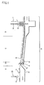
- Figure 1 is a schematic view showing an apparatus for producing an LB film;
- Figure 2 is a schematic view showing a conventional apparatus for producing an LB film as has already been described; and
- Figure 3 is a schematic view showing a control loop for regulating surface pressure of the monomolecular film on the liquid surface and a control loop for regulating liquid level in the compression region in an apparatus for producing an LB film, said control loops being used in the apparatus of Figure 1 or Figure 2.
-
- Referring to Figure 1, the apparatus has a
channel 10 having a spreading region (S), a decoupling region (DS), a compressing region (C) and a depositing region (D). Pure water or other liquid flows from the region S to the region D through the region DS and the region C. In the region S,solution 14 containing a material of which the LB film consists is spread from anozzle 19 onto the surface of the flowing liquid where it disperses so thatmolecules 11 of the material spread over theliquid phase 13. Subsequently, the flow of liquid transports thespread molecules 11 to the region C through the region DS. The material is compressed in the region C and the solvent is evaporated in the regions C and D so as to form a monomolecular film in which each of themolecules 11 is oriented to the same direction. In order to compress the material uniformly, the flow should be smooth and stable. The bottom surface of the tank in the region C preferably falls gently toward the region D and in this embodiment, the angle of the bottom surface was set at 0.24 degrees. - In the region D, a
substrate 15 attached to a transferring means 16 is moved repeatedly in the perpendicular direction to the liquid surface as shown byarrows 17 so as to be immersed in the liquid and then raised, wherebymonomolecular films 12 are deposited on thesubstrate 15 and an LB film is obtained. In the present apparatus, rapid liquid descent takes place in the decoupling region (DS) in order to prevent backflow of the material of the monomolecular film. The water level at the outlet from the region S is higher than that at the entrance to the region C, and these are connected by a relatively rapidly descending liquid surface in the region DS (18), i.e. the angle of descent is larger than that of the descending liquid surface in the region C. - In order to provide the descending liquid surface in the region DS, the bottom surface in the region DS which descends toward the region C has an angle of descent which is larger than the angle of descent of the bottom surface in the region C. The bottom surface in the region DS may define a liquid path that descends abruptly from the region S into the region DS.
- The angle () of the descending bottom surface in the region DS is preferably from 5 to 30 times the angle of the bottom surface in the region C. For example, the descending bottom surface in the region DS preferably has an angle of 2 to 10 degrees with reference to the horizontal, and in this embodiment, the angle is 5 degrees. In addition, the abrupt descent in the region DS preferably has a height (h) of 1 to 5 mm so as to minimise the occurrence of a turbulent flow around the region DS. The height (h) is the difference between the highest lower surface in the region DS and the highest bottom surface in the region C, and in this embodiment, the height (h) is 2 mm. In an embodiment of the present apparatus provided with a region DS, the fluctuation of the surface pressure of the monomolecular film in the region D can be suppressed to within 10% of the predetermined surface pressure.
- Next, materials which can make an LB film using the apparatus described above and fluctuations of the surface pressure when these materials are used will be explained.
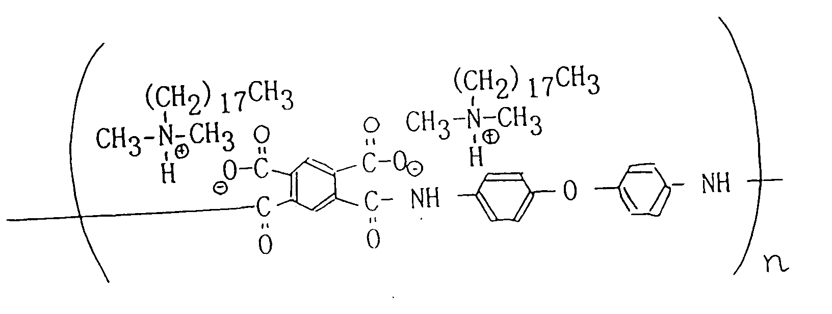
- A vast range of film forming materials can be used provided that they can form an LB film using a conventional LB film producing apparatus. Examples of the materials include polymers such as polyisobutylmethacrylate (PIBM), polylactic acid (PLA), polyamic acid which is a precursor of polyimide etc. and low molecular weight materials such as fatty acids e.g. docosanoic acid and 22-tricosenoic acid. Polyamic acid is a material of formula.
- The above materials may be dissolved into a suitable organic solvent such as chloroform to provide a solution which then is spread dropwise onto the water phase.
- When an LB film was formed using the apparatus in accordance with the embodiment of the invention with the material described above, predetermined surface pressure on the monomolecular film in the region C and the maximum fluctuation of the surface pressure are shown in Table 1. Further, the maximum fluctuation of the surface pressure of the monomolecular layer which was formed by using an apparatus which did not have the region DS is shown in Table 1.
Material Predetermined surface pressure Maximum fluctuation with region DS (h=2mm) without region DS PIBM 10 (mN/m) ± 0.5 (mN/m) ± 3 (mN/m) PLA 6 ± 0.5 ± 3 polyamic acid 30 ± 0.8 ± 4 docosanoic acid 27 ± 0.7 ± 4 22-tricosenoic acid 27 ± 0.7 ± 4 - As described in Table 1, when docosanic acid was used as the film forming material, the fluctuation of the surface pressure in the region D could be suppressed to ± 3% of the predetermined surface pressure and at least 4000 layers of the monomolecular film could be deposited continuously on a 3 inch diameter silicon wafer. Deposition took about 1000 minutes. Further, when the LB film made up of 4000 layers of docosanoic acid monomolecular film was observed using a polarizing microscope, a clear domain structure could be observed showing that the monomolecular films were produced uniformly in each step.
- In case of setting a predetermined surface pressure, the effect of the region DS is clearly apparent. For example, in the case where an LB film was produced by using PIBM with an apparatus which did not have the region DS, the surface pressure fluctuated by about ± 30% of the predetermined value. Although it was attempted to form an LB film on the 3 inch diameter silicon wafer, after 13 minutes had elapsed and 50 layers of monomolecular film had been deposited, control of the surface pressure could not be maintained and oscillation developed. In contrast, using the apparatus of the embodiment according to the present invention as has already been described, the fluctuation of the surface pressure was suppressed within ± 5% and 4000 layers of monomolecular film could be deposited on the silicon wafer.
- Next, 400 layers of PIBM monomolecular film were deposited on a silicon wafer using the apparatus having the region DS to form an LB film and then the optical waveguide characteristics of the LB film at the 633 nm wavelength of light was measured. The optical damping coefficient was 3 dB/cm. In contrast, 400 layers of PIBM monomolecular layers were deposited on a silicon wafer using the apparatus which did not have the region DS and then the optical waveguide characteristics of the LB film at the 633 nm wavelength of light was measured. The optical damping coefficient was 12 dB/cm.
- The above examples show that using the apparatus of the invention, a high quality LB film can be produced stably. Using the apparatus of the present invention, an LB film laminated from two or more kinds of monomolecular film which are made of different materials can be produced. The substrate on which the LB film is produced preferably has a flat surface. For example, silicon wafer, glass, mica and a plastic such as polycarbonate can be used. When a silicon wafer or glass is used as the substrate, the surface can be cleaned using cleaning methods known in processes for producing semiconductors, such as the RCA method.
Claims (13)
- An apparatus for producing Langmuir Blodgett film continuously comprising:a tank having a spreading region (S) for spreading over the surface of liquid in the tank a material from which a monomolecular film can be formed, a compressing region (C) for compressing the material on the liquid surface to form the monomolecular film, and a deposition region (D) at which the monomolecular film becomes deposited on a substrate;means for causing liquid to flow continuously from the spreading region to the deposition region through the compression region;first control means for controlling the amount of liquid inflow in response to the liquid level so as to maintain the level in the deposition region at a predetermined value;second control means for regulating the supply of the film forming material in response to the surface pressure of the monomolecular film so as to maintain the surface pressure at a predetermined value;means for defining a flow path for the liquid such that the depth of the liquid flowing through the compression region (C) is less than the depth of the liquid flowing through the spreading region (S) and the depth of the liquid flowing through the deposition region (D), characterised in that:a decoupling region (DS) is provided for flow of liquid from the spreading region (S) to the compression region (C) and the spreading region (S) joins the decoupling region (DS) at a vertical position (h) where it is above the highest liquid level in the compression region (C), the bottom of the decoupling region (DS) having a tilt angle () greater than that of the compression region (C).
- The apparatus of claim 1, wherein the bottom surface of the compression region (C) in the tank is even, and the even surface descends toward the deposition region (D).
- The apparatus of claim 1 or 2, wherein the bottom surface of the decoupling region (DS) is even and descends towards the compression region (C).
- The apparatus of claim 1, 2 or 3, wherein the difference in vertical positions is 1 mm to 5mm.
- The apparatus of any preceding claim, wherein the angle of slope provided by the bottom surface of the compression region (C) is from 0.1 to 2 degrees.
- The apparatus of claim 5, wherein the angle of a slope provided by the bottom surface of the decoupling region (DS) is from 2 to 10 degrees.
- The apparatus of any preceding claim, wherein the film forming material comprises a polymer selected from polyisobutylmethacrylate, polylactic acid (PLA) and polyamic acid or a derivative thereof.
- The apparatus of any of claims 1 to 6, wherein the film forming material is fatty acid.
- The apparatus of claim 8, wherein the fatty acid is docosanoic acid or 22-tricosenoic acid.
- The apparatus of any of claims 1 to 9, wherein the substrate is a silicon wafer or is of glass.
- The apparatus of any of claims 1 to 9, wherein the substrate is of mica or polycarbonate.
- A process of producing LB film using an apparatus according to any of claims 1 to 11, the process comprising dissolving material for the LB film in a solvent, spreading the material on the surface of liquid present in the spreading region (S), and compressing the LB film material in the compressing region (C) to form LB film while decoupling the spread LB film material from the compressed LB film material as it is passed via the decoupling region (DS) of said apparatus.
- A process of producing a film coated substrate wherein an LB film of compressed LB film material is produced by the process of claim 12 and a substrate is immersed one or more times into the liquid having said compressed LB film on its surface to form one or more monomolecular film layers of the LB film material on the surface of said substrate.
Applications Claiming Priority (6)
| Application Number | Priority Date | Filing Date | Title |
|---|---|---|---|
| JP8449694 | 1994-04-22 | ||
| JP8449694 | 1994-04-22 | ||
| JP84496/94 | 1994-04-22 | ||
| JP06601495A JP3262472B2 (en) | 1994-04-22 | 1995-03-24 | Langmuir Blodgett film production equipment |
| JP6601495 | 1995-03-24 | ||
| JP66014/95 | 1995-03-24 |
Publications (2)
| Publication Number | Publication Date |
|---|---|
| EP0678345A1 EP0678345A1 (en) | 1995-10-25 |
| EP0678345B1 true EP0678345B1 (en) | 1999-12-22 |
Family
ID=26407178
Family Applications (1)
| Application Number | Title | Priority Date | Filing Date |
|---|---|---|---|
| EP95302632A Expired - Lifetime EP0678345B1 (en) | 1994-04-22 | 1995-04-20 | Apparatus for producing Langmuir-Blodgett film |
Country Status (4)
| Country | Link |
|---|---|
| US (1) | US5599589A (en) |
| EP (1) | EP0678345B1 (en) |
| JP (1) | JP3262472B2 (en) |
| DE (1) | DE69514027T2 (en) |
Families Citing this family (14)
| Publication number | Priority date | Publication date | Assignee | Title |
|---|---|---|---|---|
| US6296803B1 (en) * | 1995-12-20 | 2001-10-02 | Plastipak Packaging, Inc. | Method for making a multi-layer blow molded container |
| DE69809122T2 (en) * | 1997-05-30 | 2003-04-03 | Canon K.K., Tokio/Tokyo | Device for producing Lagmuir-Blodgett films |
| CA2385911A1 (en) * | 2002-05-10 | 2003-11-10 | Nanometrix Inc. | Method and apparatus for two dimensional assembly of particles |
| US7241341B2 (en) | 2002-05-10 | 2007-07-10 | Nanometrix Inc. | Method and apparatus for two dimensional assembly of particles |
| WO2005061382A1 (en) * | 2003-12-24 | 2005-07-07 | Nanometrix Inc. | Continuous production of carbon nanotubes |
| DE602007003340D1 (en) | 2006-09-26 | 2009-12-31 | Canon Kk | CONTRAPTION |
| US8425985B2 (en) * | 2008-08-22 | 2013-04-23 | Corning Incorporated | Method for particulate coating |
| US8663745B2 (en) | 2010-06-04 | 2014-03-04 | Canon Kabushiki Kaisha | Film-forming method based on LB method |
| FR2977810A1 (en) * | 2011-07-13 | 2013-01-18 | Commissariat Energie Atomique | INSTALLATION AND METHOD FOR DEPOSITING OR ADJUSTABLE PARTICLE FILM OF ADJUSTABLE WIDTH TO A SCROLLING SUBSTRATE |
| FR2985249B1 (en) * | 2012-01-02 | 2014-03-07 | Commissariat Energie Atomique | METHOD OF TRANSFERRING OBJECTS TO A SUBSTRATE USING A COMPACT PARTICLE FILM |
| FR2986722B1 (en) * | 2012-02-10 | 2014-03-28 | Commissariat Energie Atomique | METHOD FOR TRANSFERRING OBJECTS TO A SUBSTRATE USING A COMPACT PARTICLE FILM, WITH A CONNECTER IMPLEMENTATION STEP ON THE OBJECTS |
| FR2986720B1 (en) * | 2012-02-10 | 2014-03-28 | Commissariat Energie Atomique | METHOD FOR DEPOSITING PARTICLES ON A SUBSTRATE, COMPRISING A STEP FOR STRUCTURING A PARTICLE FILM ON A LIQUID CONVEYOR |
| FR2986721B1 (en) * | 2012-02-10 | 2014-06-27 | Commissariat Energie Atomique | METHOD FOR DEPOSITING A PARTICLE FILM ON A SUBSTRATE VIA A LIQUID CONVEYER, COMPRISING A STRUCTURING STEP OF THE FILM ON THE SUBSTRATE |
| CN113097384B (en) * | 2021-03-31 | 2023-11-21 | 南京大学 | A method for preparing two-dimensional molecular monolayers |
Family Cites Families (11)
| Publication number | Priority date | Publication date | Assignee | Title |
|---|---|---|---|---|
| JPS6227069A (en) * | 1985-07-30 | 1987-02-05 | Fuji Photo Film Co Ltd | Device for forming solid monomolecular film |
| US4722856A (en) * | 1986-01-02 | 1988-02-02 | Molecular Electronics Corporation | Method and apparatus for depositing monomolecular layers on a substrate |
| DE68916298T2 (en) * | 1988-03-28 | 1994-10-06 | Canon Kk | Polymeric compounds and recording medium therefrom. |
| DE3828836A1 (en) * | 1988-08-25 | 1990-03-01 | Hoechst Ag | METHOD AND DEVICE FOR PRODUCING THIN LAYERS |
| JPH02244611A (en) * | 1989-03-16 | 1990-09-28 | Nippon Steel Corp | Organic thin film patterning method |
| JPH02280821A (en) * | 1989-04-20 | 1990-11-16 | Sanyo Electric Co Ltd | Membrane permeable selectively to oxygen |
| DE4105049A1 (en) * | 1991-02-19 | 1992-08-20 | Philips Patentverwaltung | Integrated optical polariser simpler prodn. with Langmuir Blodgett absorber film - of amphiphilic dyestuff and pref. mols, forcing fixed geometry, esp. of fatty acid |
| JPH04367720A (en) * | 1991-06-12 | 1992-12-21 | Canon Inc | Method and apparatus for forming monomolecular film or monomolecular cumulative film |
| JP2949651B2 (en) * | 1991-07-18 | 1999-09-20 | キヤノン株式会社 | Method of manufacturing electrode substrate and recording medium |
| US5143745A (en) * | 1991-08-16 | 1992-09-01 | Maganas Thomas C | Intermittent film deposition method and system |
| DE59302244D1 (en) * | 1992-08-19 | 1996-05-23 | Hoechst Ag | Method and device for producing ultra-thin layers and layer elements |
-
1995
- 1995-03-24 JP JP06601495A patent/JP3262472B2/en not_active Expired - Fee Related
- 1995-04-18 US US08/423,697 patent/US5599589A/en not_active Expired - Lifetime
- 1995-04-20 DE DE69514027T patent/DE69514027T2/en not_active Expired - Fee Related
- 1995-04-20 EP EP95302632A patent/EP0678345B1/en not_active Expired - Lifetime
Also Published As
| Publication number | Publication date |
|---|---|
| DE69514027D1 (en) | 2000-01-27 |
| JPH081058A (en) | 1996-01-09 |
| JP3262472B2 (en) | 2002-03-04 |
| EP0678345A1 (en) | 1995-10-25 |
| DE69514027T2 (en) | 2000-05-31 |
| US5599589A (en) | 1997-02-04 |
Similar Documents
| Publication | Publication Date | Title |
|---|---|---|
| US5599589A (en) | Apparatus and process for producing organic mono molecular or multilayer films | |
| Born | Role of Meniscus Shape in Large-Area Convective Particle Assembly | |
| Im et al. | Thickness control of colloidal crystals with a substrate dipped at a tilted angle into a colloidal suspension | |
| US7298544B2 (en) | Method for patterning self-assembled colloidal photonic crystals and method for fabricating 3-dimensional photonic crystal waveguides of an inverted-opal structure using the patterning method | |
| DE69303149T2 (en) | Meniscus coating process | |
| US6013315A (en) | Dispense nozzle design and dispense method | |
| US20110135834A1 (en) | Modular transfer apparatus and process | |
| US6770330B2 (en) | Method for producing a continuous, large-area particle film | |
| US5143745A (en) | Intermittent film deposition method and system | |
| US5633043A (en) | Process for fabricating thin films | |
| Hur et al. | Fabrication of high-quality non-close-packed 2D colloid crystals by template-guided Langmuir–Blodgett particle deposition | |
| EP0881000B1 (en) | Apparatus for producing langmuir-blodgett film | |
| Isobe et al. | Effect of substrate surfaces for crystal growth of a photochromic diarylethene by sublimation | |
| EP0518366B1 (en) | Method and apparatus for forming LANGMUIR-BLODGETT films | |
| Shiratori et al. | Automatic film formation system for ultra-thin organic/inorganic hetero-structure by mass-controlled layer-by-layer sequential adsorption method with ‘nm’scale accuracy | |
| Karthaus et al. | Control of droplet size and spacing in micrometer-sized polymeric dewetting patterns | |
| Dziomkina et al. | Towards true 3-dimensional BCC colloidal crystals with controlled lattice orientation | |
| US5670624A (en) | Two-dimensional aggregation and fixation of protein by injection into a substrate solution having higher surface tension and specific gravity | |
| KR100447780B1 (en) | Chemical adsorption solution and method of producing chemically adsorbed film using the chemical adsorption solution | |
| JPH0377667A (en) | Formation of monomolecular film and device therefor | |
| Albrecht et al. | Industrial scale production of LB layers | |
| JPH01315368A (en) | Process and device for preparing organic thin film | |
| JPH05319999A (en) | Method for manufacturing organic crystal thin film | |
| JPS61278374A (en) | Preparation of lb membrane | |
| JPH067737A (en) | Continuous preparation of built-up film |
Legal Events
| Date | Code | Title | Description |
|---|---|---|---|
| PUAI | Public reference made under article 153(3) epc to a published international application that has entered the european phase |
Free format text: ORIGINAL CODE: 0009012 |
|
| AK | Designated contracting states |
Kind code of ref document: A1 Designated state(s): DE FR GB |
|
| 17P | Request for examination filed |
Effective date: 19960305 |
|
| 17Q | First examination report despatched |
Effective date: 19980205 |
|
| GRAG | Despatch of communication of intention to grant |
Free format text: ORIGINAL CODE: EPIDOS AGRA |
|
| GRAG | Despatch of communication of intention to grant |
Free format text: ORIGINAL CODE: EPIDOS AGRA |
|
| GRAG | Despatch of communication of intention to grant |
Free format text: ORIGINAL CODE: EPIDOS AGRA |
|
| GRAH | Despatch of communication of intention to grant a patent |
Free format text: ORIGINAL CODE: EPIDOS IGRA |
|
| GRAH | Despatch of communication of intention to grant a patent |
Free format text: ORIGINAL CODE: EPIDOS IGRA |
|
| GRAA | (expected) grant |
Free format text: ORIGINAL CODE: 0009210 |
|
| AK | Designated contracting states |
Kind code of ref document: B1 Designated state(s): DE FR GB |
|
| REF | Corresponds to: |
Ref document number: 69514027 Country of ref document: DE Date of ref document: 20000127 |
|
| ET | Fr: translation filed | ||
| PLBE | No opposition filed within time limit |
Free format text: ORIGINAL CODE: 0009261 |
|
| STAA | Information on the status of an ep patent application or granted ep patent |
Free format text: STATUS: NO OPPOSITION FILED WITHIN TIME LIMIT |
|
| 26N | No opposition filed | ||
| REG | Reference to a national code |
Ref country code: GB Ref legal event code: IF02 |
|
| PGFP | Annual fee paid to national office [announced via postgrant information from national office to epo] |
Ref country code: GB Payment date: 20040406 Year of fee payment: 10 |
|
| PGFP | Annual fee paid to national office [announced via postgrant information from national office to epo] |
Ref country code: FR Payment date: 20040421 Year of fee payment: 10 Ref country code: DE Payment date: 20040421 Year of fee payment: 10 |
|
| PG25 | Lapsed in a contracting state [announced via postgrant information from national office to epo] |
Ref country code: GB Free format text: LAPSE BECAUSE OF NON-PAYMENT OF DUE FEES Effective date: 20050420 |
|
| PG25 | Lapsed in a contracting state [announced via postgrant information from national office to epo] |
Ref country code: DE Free format text: LAPSE BECAUSE OF NON-PAYMENT OF DUE FEES Effective date: 20051101 |
|
| GBPC | Gb: european patent ceased through non-payment of renewal fee |
Effective date: 20050420 |
|
| PG25 | Lapsed in a contracting state [announced via postgrant information from national office to epo] |
Ref country code: FR Free format text: LAPSE BECAUSE OF NON-PAYMENT OF DUE FEES Effective date: 20051230 |
|
| REG | Reference to a national code |
Ref country code: FR Ref legal event code: ST Effective date: 20051230 |