EP0677865B1 - X-ray tube noise and vibration reduction - Google Patents
X-ray tube noise and vibration reduction Download PDFInfo
- Publication number
- EP0677865B1 EP0677865B1 EP95302499A EP95302499A EP0677865B1 EP 0677865 B1 EP0677865 B1 EP 0677865B1 EP 95302499 A EP95302499 A EP 95302499A EP 95302499 A EP95302499 A EP 95302499A EP 0677865 B1 EP0677865 B1 EP 0677865B1
- Authority
- EP
- European Patent Office
- Prior art keywords
- anode
- ray tube
- shank
- granules
- washer
- Prior art date
- Legal status (The legal status is an assumption and is not a legal conclusion. Google has not performed a legal analysis and makes no representation as to the accuracy of the status listed.)
- Expired - Lifetime
Links
- 230000009467 reduction Effects 0.000 title description 7
- 239000008187 granular material Substances 0.000 claims description 20
- 238000002955 isolation Methods 0.000 claims description 11
- 239000000463 material Substances 0.000 claims description 11
- 238000000034 method Methods 0.000 claims description 7
- 229920000642 polymer Polymers 0.000 claims description 2
- 239000008188 pellet Substances 0.000 claims 3
- 230000008878 coupling Effects 0.000 claims 1
- 238000010168 coupling process Methods 0.000 claims 1
- 238000005859 coupling reaction Methods 0.000 claims 1
- 230000008901 benefit Effects 0.000 description 5
- 238000013461 design Methods 0.000 description 5
- 239000006096 absorbing agent Substances 0.000 description 3
- 238000013459 approach Methods 0.000 description 3
- 239000011521 glass Substances 0.000 description 3
- 238000012986 modification Methods 0.000 description 3
- 230000004048 modification Effects 0.000 description 3
- 230000005534 acoustic noise Effects 0.000 description 2
- 230000004075 alteration Effects 0.000 description 2
- 238000009826 distribution Methods 0.000 description 2
- 238000004519 manufacturing process Methods 0.000 description 2
- 238000005259 measurement Methods 0.000 description 2
- 230000001133 acceleration Effects 0.000 description 1
- 230000015556 catabolic process Effects 0.000 description 1
- 230000008859 change Effects 0.000 description 1
- 238000002591 computed tomography Methods 0.000 description 1
- 239000007799 cork Substances 0.000 description 1
- 238000006731 degradation reaction Methods 0.000 description 1
- 230000001419 dependent effect Effects 0.000 description 1
- 238000010894 electron beam technology Methods 0.000 description 1
- 230000005284 excitation Effects 0.000 description 1
- 230000017525 heat dissipation Effects 0.000 description 1
- 238000013508 migration Methods 0.000 description 1
- 230000005012 migration Effects 0.000 description 1
- 239000002245 particle Substances 0.000 description 1
- 238000012545 processing Methods 0.000 description 1
- 230000000717 retained effect Effects 0.000 description 1
- 238000004904 shortening Methods 0.000 description 1
Images


Classifications
-
- F—MECHANICAL ENGINEERING; LIGHTING; HEATING; WEAPONS; BLASTING
- F16—ENGINEERING ELEMENTS AND UNITS; GENERAL MEASURES FOR PRODUCING AND MAINTAINING EFFECTIVE FUNCTIONING OF MACHINES OR INSTALLATIONS; THERMAL INSULATION IN GENERAL
- F16F—SPRINGS; SHOCK-ABSORBERS; MEANS FOR DAMPING VIBRATION
- F16F7/00—Vibration-dampers; Shock-absorbers
- F16F7/01—Vibration-dampers; Shock-absorbers using friction between loose particles, e.g. sand
-
- H—ELECTRICITY
- H01—ELECTRIC ELEMENTS
- H01J—ELECTRIC DISCHARGE TUBES OR DISCHARGE LAMPS
- H01J35/00—X-ray tubes
- H01J35/02—Details
- H01J35/04—Electrodes ; Mutual position thereof; Constructional adaptations therefor
- H01J35/08—Anodes; Anti cathodes
- H01J35/10—Rotary anodes; Arrangements for rotating anodes; Cooling rotary anodes
- H01J35/101—Arrangements for rotating anodes, e.g. supporting means, means for greasing, means for sealing the axle or means for shielding or protecting the driving
- H01J35/1017—Bearings for rotating anodes
-
- H—ELECTRICITY
- H05—ELECTRIC TECHNIQUES NOT OTHERWISE PROVIDED FOR
- H05G—X-RAY TECHNIQUE
- H05G1/00—X-ray apparatus involving X-ray tubes; Circuits therefor
- H05G1/08—Electrical details
- H05G1/26—Measuring, controlling or protecting
- H05G1/54—Protecting or lifetime prediction
-
- H—ELECTRICITY
- H01—ELECTRIC ELEMENTS
- H01J—ELECTRIC DISCHARGE TUBES OR DISCHARGE LAMPS
- H01J2235/00—X-ray tubes
- H01J2235/10—Drive means for anode (target) substrate
- H01J2235/1093—Measures for preventing vibration
Definitions
- the invention relates generally to X-ray tubes of the rotating anode type and is concerned more particularly with an X-ray tube having an anode structure utilizing an anode shank vibration absorber to reduce acoustic noise and vibration produced by the X-ray tube.
- a conventional X-ray tube of the rotating anode type comprises a vacuum envelope having transversely disposed therein an anode target disk having a radially sloped surface with a focal spot area disposed in spaced alignment with an electron emitting cathode.
- a beam of electrons from the cathode being focused onto the aligned focal spot area of the target strikes the focal spot area and generates X-rays.
- the kinetic energy of the electrons bombarding the focal spot area of the target is partially converted into heat.
- the target disk is rotated at approximately 3,000 to 10,000 rpm.
- the target disk is mounted on a rotatable shaft which is coupled to the vacuum tube via bearings.
- the rotation of the rotor anode structure generates vibration initiated by high rotation speeds and accelerations to which the rotor anode structure is exposed. A portion of this vibration ultimately is transmitted through the X-ray tube housing surrounding the vacuum tube.
- the space between a vacuum envelope and the housing is filled with oil which is used for X-ray vacuum tube heat dissipation and for dielectric purposes. When this vibration reaches the housing, it is radiated as noise. This acoustic noise has become a great concern to medical staffs and patients.
- the present invention provides an X-ray tube as set out in claim 1. Alternatively it provides a method of absorbing vibration as set out in claim 15.
- the loose granules are placed in an anode cavity to absorb a portion of the vibrational energy resulting from the rotation of the rotatable shaft at a location near where the primary noise is generated.
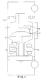
- Fig. 1 shows a simplified side view cross-section of a conventional X-ray tube with the elements shown schematically.
- Fig. 2 shows a partial side view cross-section of the X-ray tube of the present invention.
- Fig. 3A shows a distribution of relative vibration amplitudes in a frequency range of 1-10 KHz for conventional X-ray tube.
- Fig. 3B shows a distribution of relative vibrations amplitudes in a frequency range of 1-10 KHz for the present invention.
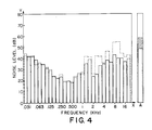
- Fig. 4 shows a noise histogram of the present invention in comparison to a noise histogram of a conventional X-ray tube.
- X-ray tube 10 is a rotating anode type X-ray tube.
- An anode assembly comprises target 12 connected to shaft 13.
- Bearing assembly 14 serves to facilitate the rotation of anode target 12.
- the anode is spaced apart from and oppositely disposed from cathode 15.
- the cathode structure includes a cathode head and a filament which is connected to an appropriate power source.
- the cathode and anode are located within a vacuum envelope of X-ray insert 11.
- Stator assembly 16 is placed around the neck portion of the vacuum envelope of X-ray insert 11. When stator 16 generates a rotating magnetic field the rotor which opposes stator through the wall of the vacuum envelope (not shown) and anode assembly rotates at a predetermined high speed.
- An electron beam is generated from cathode 15 by applying a high voltage between cathode 15 and anode target 12, and is radiated onto the focal spot area 17.
- the electrons bombard the focal spot area with sufficient kinetic energy to generate X-rays.
- the X-rays emitted from the surface in the direction represented by dotted lines in Fig.1 are used to produce medical images.
- the quality of image obtained by processing the data from the X-ray tube depends on changes in relative position of the target. All uncontrolled changes in position of the focal spot are undesirable.
- One of the reasons for migration of the focal spot 17 on anode target 12 is vibration of the X-ray tube components in operation, induced by rotation of the anode structure 12-14.
- the vibrational energy initiated by rotation of anode target 22 and anode shaft 23 via bearing assembly 24 is transmitted to anode shank cavity 25 which is defined by outer wall 26 of anode shank and anode sleeve wall 27.
- Granules 20 are distributed loosely in anode cavity 25 and retained inside this cavity by means of retaining washer 28 which is secured by clip ring 29.
- Retaining washer 28 comprises vibration isolation material 21 deposited on the inner surface of the washer facing the granules. Cork or a polymer acoustic dampener can be used as a vibration isolation material.
- Isolation material 21 absorbs additional vibrational energy of granules 20 when the X-ray tube is operated in anode down or horizontal position.
- the experimental graphs of Fig. 3A-3B show the reduction level affected by the new design of X-ray tube (Fig. 3B) compared to the conventional one (Fig. 3A). Results were obtained for the granules having diameters of about 4 mm and weight 0.25 gm .
- the diameter of the granules may vary depending on the type of the X-ray device in the approximate range of 0.1-1 cm, and weight may vary in the approximate range of 0.1 gm - 1 gm.
- the noise histograms of Fig. 4 show a comparison of sound pressure level for conventional X-ray tube (dotted line) and the present invention (solid line) respectively.
- the preferred series of 1/3 octave bands for these acoustic measurements cover the audible range in ten bands.
- the center frequencies of these bands are shown on axis X.
- the vibration absorber of the present invention allows a 9.3 dB(A) reduction in noise (cross-slashed column). This data was calculated with respect to an A-weighted sound pressure level algorithm.
- any use of unconstrained or partially constrained particles applied to the surface of the X-ray tube so as to absorb vibrational energy from said surface should be recognized as an application of this invention.
- the granules may be applied outside of the X-ray insert in proximity to the neck portion of the X-ray tube, or inside of the X-ray insert in proximity to the cathode structure.
- the disclosed invention allows reducing the vibrational energy at the source of its excitation before this energy is transmitted to the vacuum envelope and further to the housing of the X-ray tube.
Landscapes
- Engineering & Computer Science (AREA)
- General Engineering & Computer Science (AREA)
- Mechanical Engineering (AREA)
- Health & Medical Sciences (AREA)
- General Health & Medical Sciences (AREA)
- Toxicology (AREA)
- X-Ray Techniques (AREA)
Description
Claims (19)
- An X-ray tube comprising a housing (10), an X-ray insert (11-17) disposed within the housing, the insert having a vacuum envelope (11), first and second electrode structures disposed within the envelope, the first electrode structure forming an anode, the anode comprising a target (12, 22) and a rotatable shaft (13) attached to said target, the second electrode structure forming a cathode (15) which is spaced apart from and oppositely disposed to said anode, the tube further comprising means for dissipating the vibrational energy transmitted by said shaft characterised in that said vibration absorbing means comprises granules (20) being distributed loosely adjacent said X-ray insert (11-17) in energy exchanging relationship with the surface of the X-ray insert (11-17) so as to absorb vibrational energy from said surface.
- An X-ray tube as claimed in claim 1 comprising containment means (26, 27) for said granules, said containment means defining a space (25) which does not intersect the axis about which said shaft is rotatable.
- An X-ray tube as claimed in claim 2 wherein the vacuum envelope is formed with a neck portion and a bulb portion; and the anode has a first end (22) at which the target is mounted disposed within said bulb portion and a second end (24) disposed within said neck portion, said second end further comprising an anode sleeve (27) and an anode shank (26) coupling by a retaining means (28, 29) to define said containment means as an anode cavity (25) therebetween within which said granules (20) are distributed loosely.
- An X-ray tube as claimed in claim 3 wherein said retaining means comprises a washer (28).
- An X-ray tube as claimed in claim 4 wherein said retaining means further comprises an isolation material (21), said isolation material being fixed to said washer from an inner side of said anode cavity.
- An X-ray tube as claimed in claim 5 wherein said retaining means further comprises a clip ring (29), said clip ring being fixed to said washer in opposed relationship to said isolation material.
- An X-ray tube as claimed in claim 3 wherein the X-ray insert comprises a rotor shaft journaled in bearings for rotation within said envelope; said target having a portion secured to and engaging said shaft for rotation therewith; the anode shank being mounted on said rotor shaft, said shank having an outer cylindrical surface (26); the anode sleeve (27) being fixed to said neck portion of said vacuum envelope, said anode sleeve wall spaced apart in opposed relationship to said outer cylindrical surface of said anode shank; the retaining means comprising an anode seal connecting said outer wall of said anode shank to said anode sleeve; a washer, said washer spaced apart to said anode seal in opposed relationship to said anode seal and connecting said outer surface of said anode shank to said anode sleeve; said washer, anode sleeve, anode seal and outer surface of said anode shank defining said anode cavity (25).
- An X-ray tube as claimed in claim 7 further comprising a clip ring (29), said clip ring retaining said washer from the outer side of said anode cavity.
- An X-ray tube as claimed in any one of claims 3 to 8 wherein said anode cavity further comprises an isolation material (21) in the interior of said cavity, said isolation material deposited on said washer.
- An X-ray tube as claimed in claim 9 wherein said isolation material is a plastic polymer.
- An X-ray tube as claimed in any one of claims 1 to 10 wherein said granules are made of lead.
- An X-ray tube as claimed in claim 11 wherein said granules are pellets.
- An X-ray tube as claimed in claim 12 wherein the diameter of each of said pellets is in the range 0.1 -1 cm.
- An X-ray tube as claimed in claim 13 wherein the diameter of each said pellet is 0.4 cm.
- A method of attenuating vibrational energy of an X-ray tube generated by a rotor shaft within the X-ray tube having a rotating anode structure which is coupled to a vacuum envelope of said X-ray tube via bearings, the X-ray tube comprising a housing (10), an X-ray insert (11-17) disposed within the housing, the insert having a vacuum envelope (11), first and second electrode structures disposed within the envelope, the first electrode structure forming an anode, the anode comprising a target (12, 22) and a rotatable shaft (13) attached to said target, the second electrode structure forming a cathode (15) which is spaced apart from and oppositely disposed to said anode, characterised by loosely distributing granules (20) adjacent said insert (11-17) in energy exchanging relationship with the surface of the X-ray insert (11-17) so as to absorb vibrational energy from said surface.
- A method as claimed in claim 15 comprising defining a space within which said granules (20) are distributed, said space not intersecting the axis about which said shaft is rotatable.
- A method as claimed in claim 16 wherein said space is defined by providing an anode shank at a neck portion of said X-ray tube, said shank having an outer cylindrical surface; mounting said anode shank to said rotor shaft; forming an anode cavity in proximity to said bearings between said outer cylindrical surface of said shank and an anode sleeve wall of said rotating anode structure; and shielding said anode cavity with said granules by a cover, wherein, in operation, the vibrational energy excited by said rotor shaft is transmitted via bearings to said anode cavity and absorbed by said granules.
- A method as claimed in claim 17 wherein said cover for shielding said anode cavity is a washer (28) with an isolation material (21) which is deposited on said washer and facing said granules.
- A method as claimed in claim 18 further comprising a step of securing said cover of said anode cavity by clip ring (29), wherein said clip ring is fixed to said cover from the outer side of said anode cavity.
Applications Claiming Priority (2)
| Application Number | Priority Date | Filing Date | Title |
|---|---|---|---|
| US227215 | 1994-04-13 | ||
| US08/227,215 US5425067A (en) | 1994-04-13 | 1994-04-13 | X-ray tube noise and vibration reduction |
Publications (2)
| Publication Number | Publication Date |
|---|---|
| EP0677865A1 EP0677865A1 (en) | 1995-10-18 |
| EP0677865B1 true EP0677865B1 (en) | 1998-07-22 |
Family
ID=22852228
Family Applications (1)
| Application Number | Title | Priority Date | Filing Date |
|---|---|---|---|
| EP95302499A Expired - Lifetime EP0677865B1 (en) | 1994-04-13 | 1995-04-13 | X-ray tube noise and vibration reduction |
Country Status (4)
| Country | Link |
|---|---|
| US (1) | US5425067A (en) |
| EP (1) | EP0677865B1 (en) |
| JP (1) | JPH0855694A (en) |
| DE (1) | DE69503553T2 (en) |
Families Citing this family (13)
| Publication number | Priority date | Publication date | Assignee | Title |
|---|---|---|---|---|
| US5802140A (en) | 1997-08-29 | 1998-09-01 | Varian Associates, Inc. | X-ray generating apparatus with integral housing |
| US6361208B1 (en) | 1999-11-26 | 2002-03-26 | Varian Medical Systems | Mammography x-ray tube having an integral housing assembly |
| US6480571B1 (en) | 2000-06-20 | 2002-11-12 | Varian Medical Systems, Inc. | Drive assembly for an x-ray tube having a rotating anode |
| US6751293B1 (en) | 2001-10-05 | 2004-06-15 | Varian Medical Systems, Inc. | Rotary component support system |
| US6643221B1 (en) * | 2001-11-06 | 2003-11-04 | Schlumberger Technology Corporation | Structures and methods for damping tool waves particularly for acoustic logging tools |
| US6819742B1 (en) * | 2001-12-07 | 2004-11-16 | Varian Medical Systems, Inc. | Integrated component mounting system for use in an X-ray tube |
| US7933213B1 (en) * | 2005-09-30 | 2011-04-26 | At&T Intellectual Property Ii, L.P. | Method and apparatus for monitoring and restoring time division multiplexing circuits |
| JP5218728B2 (en) * | 2007-09-11 | 2013-06-26 | 株式会社島津製作所 | Round-trip X-ray equipment |
| CN103541460B (en) * | 2013-11-08 | 2016-01-20 | 同济大学 | Novel tuning granular mass damper |
| CN108386473B (en) * | 2018-05-02 | 2019-12-27 | 河南创辉水利水电工程有限公司 | Hydroelectric set vibration absorbing device |
| JP7085441B2 (en) * | 2018-09-12 | 2022-06-16 | 川崎重工業株式会社 | Damper bearings and dampers |
| CN113471040A (en) * | 2021-07-23 | 2021-10-01 | 昆山医源医疗技术有限公司 | X-ray tube assembly |
| US11555793B1 (en) | 2021-08-04 | 2023-01-17 | International Business Machines Corporation | Anti-vibration fixturing system for nondestructive testing |
Family Cites Families (11)
| Publication number | Priority date | Publication date | Assignee | Title |
|---|---|---|---|---|
| US2417347A (en) * | 1943-07-06 | 1947-03-11 | Lockheed Aircraft Corp | Vibration damper |
| US4207841A (en) * | 1945-05-19 | 1980-06-17 | The United States Of America As Represented By The Secretary Of The Army | Dipole antenna for proximity fuze |
| US3855492A (en) * | 1973-11-19 | 1974-12-17 | Machlett Lab Inc | Vibration reduced x-ray anode |
| DE2554267A1 (en) * | 1975-12-03 | 1977-06-16 | Kuebler & Co | STICK FOR TENNIS O.DGL. GAMES |
| JPS5778756A (en) * | 1980-11-04 | 1982-05-17 | Hitachi Ltd | Rotary anode x-ray tube device |
| CS232586B1 (en) * | 1983-03-31 | 1985-02-14 | Frantisek Starek | Seating of rotating parts of a x-ray tube's anode |
| JPS603898A (en) * | 1983-06-22 | 1985-01-10 | Hitachi Ltd | Rotating anode X-ray tube device |
| JPS63149410A (en) * | 1986-12-11 | 1988-06-22 | Mitsubishi Heavy Ind Ltd | Rotating body supported by magnetic bearing |
| US4935948A (en) * | 1988-12-12 | 1990-06-19 | General Electric Company | X-ray tube noise reduction by mounting a ring mass |
| US5253284A (en) * | 1992-06-01 | 1993-10-12 | General Electric Company | X-Ray tube noise reduction using non-glass inserts |
| US5265147A (en) * | 1992-06-01 | 1993-11-23 | General Electric Company | X-ray tube noise reduction using stator mass |
-
1994
- 1994-04-13 US US08/227,215 patent/US5425067A/en not_active Expired - Fee Related
-
1995
- 1995-04-12 JP JP7110264A patent/JPH0855694A/en active Pending
- 1995-04-13 DE DE69503553T patent/DE69503553T2/en not_active Expired - Fee Related
- 1995-04-13 EP EP95302499A patent/EP0677865B1/en not_active Expired - Lifetime
Also Published As
| Publication number | Publication date |
|---|---|
| EP0677865A1 (en) | 1995-10-18 |
| US5425067A (en) | 1995-06-13 |
| DE69503553T2 (en) | 1998-11-19 |
| JPH0855694A (en) | 1996-02-27 |
| DE69503553D1 (en) | 1998-08-27 |
Similar Documents
| Publication | Publication Date | Title |
|---|---|---|
| US5425067A (en) | X-ray tube noise and vibration reduction | |
| US6361208B1 (en) | Mammography x-ray tube having an integral housing assembly | |
| JP2009545840A (en) | X-ray tube with transmissive anode | |
| US5802140A (en) | X-ray generating apparatus with integral housing | |
| US5493599A (en) | Off-focal radiation limiting precollimator and adjustable ring collimator for x-ray CT scanners | |
| EP1611590B1 (en) | X-ray tube having an internal radiation shield | |
| US5838762A (en) | Rotating anode for x-ray tube using interference fit | |
| EP0051295B1 (en) | X-ray tube apparatus | |
| US6212753B1 (en) | Complaint joint for interfacing dissimilar metals in X-ray tubes | |
| JP2001216928A (en) | X-ray tube | |
| US6163593A (en) | Shaped target for mammography | |
| US4935948A (en) | X-ray tube noise reduction by mounting a ring mass | |
| CN118352210A (en) | Tube core assembly for CT bulb tube | |
| JP2019192533A (en) | X-ray tube device | |
| US5253284A (en) | X-Ray tube noise reduction using non-glass inserts | |
| US5795207A (en) | Glass to metal interface X-ray tube | |
| CN222377003U (en) | Elastic foil type liquid metal bearing suitable for X-ray tube and CT bulb tube | |
| US20050123096A1 (en) | Sealed electron beam source | |
| JP2000175295A (en) | Speaker device | |
| JPS6166399A (en) | Rotary anode x-ray tube device | |
| JPS58189997A (en) | Rotating anode X-ray tube device | |
| JPS58216347A (en) | Rotating anode X-ray tube device | |
| CA1089909A (en) | Internally shielded x-ray tube | |
| CN120727541A (en) | X-ray tubes, radiation source devices and detection equipment | |
| JPS58163199A (en) | Rotating anode X-ray tube device |
Legal Events
| Date | Code | Title | Description |
|---|---|---|---|
| PUAI | Public reference made under article 153(3) epc to a published international application that has entered the european phase |
Free format text: ORIGINAL CODE: 0009012 |
|
| AK | Designated contracting states |
Kind code of ref document: A1 Designated state(s): DE NL |
|
| 17P | Request for examination filed |
Effective date: 19960326 |
|
| 17Q | First examination report despatched |
Effective date: 19961015 |
|
| GRAG | Despatch of communication of intention to grant |
Free format text: ORIGINAL CODE: EPIDOS AGRA |
|
| GRAG | Despatch of communication of intention to grant |
Free format text: ORIGINAL CODE: EPIDOS AGRA |
|
| GRAH | Despatch of communication of intention to grant a patent |
Free format text: ORIGINAL CODE: EPIDOS IGRA |
|
| GRAH | Despatch of communication of intention to grant a patent |
Free format text: ORIGINAL CODE: EPIDOS IGRA |
|
| GRAA | (expected) grant |
Free format text: ORIGINAL CODE: 0009210 |
|
| AK | Designated contracting states |
Kind code of ref document: B1 Designated state(s): DE NL |
|
| REF | Corresponds to: |
Ref document number: 69503553 Country of ref document: DE Date of ref document: 19980827 |
|
| PGFP | Annual fee paid to national office [announced via postgrant information from national office to epo] |
Ref country code: DE Payment date: 19990318 Year of fee payment: 5 |
|
| PGFP | Annual fee paid to national office [announced via postgrant information from national office to epo] |
Ref country code: NL Payment date: 19990331 Year of fee payment: 5 |
|
| PLBE | No opposition filed within time limit |
Free format text: ORIGINAL CODE: 0009261 |
|
| STAA | Information on the status of an ep patent application or granted ep patent |
Free format text: STATUS: NO OPPOSITION FILED WITHIN TIME LIMIT |
|
| 26N | No opposition filed | ||
| NLT1 | Nl: modifications of names registered in virtue of documents presented to the patent office pursuant to art. 16 a, paragraph 1 |
Owner name: VARIAN MEDICAL SYSTEMS, INC. |
|
| PG25 | Lapsed in a contracting state [announced via postgrant information from national office to epo] |
Ref country code: NL Free format text: LAPSE BECAUSE OF NON-PAYMENT OF DUE FEES Effective date: 20001101 |
|
| NLV4 | Nl: lapsed or anulled due to non-payment of the annual fee |
Effective date: 20001101 |
|
| PG25 | Lapsed in a contracting state [announced via postgrant information from national office to epo] |
Ref country code: DE Free format text: LAPSE BECAUSE OF NON-PAYMENT OF DUE FEES Effective date: 20010201 |