EP0677756B1 - Combined beam waveguide and metal cable plug connector - Google Patents
Combined beam waveguide and metal cable plug connector Download PDFInfo
- Publication number
- EP0677756B1 EP0677756B1 EP95104212A EP95104212A EP0677756B1 EP 0677756 B1 EP0677756 B1 EP 0677756B1 EP 95104212 A EP95104212 A EP 95104212A EP 95104212 A EP95104212 A EP 95104212A EP 0677756 B1 EP0677756 B1 EP 0677756B1
- Authority
- EP
- European Patent Office
- Prior art keywords
- optical fiber
- housing
- cables
- cap
- plug connector
- Prior art date
- Legal status (The legal status is an assumption and is not a legal conclusion. Google has not performed a legal analysis and makes no representation as to the accuracy of the status listed.)
- Expired - Lifetime
Links
- 239000002184 metal Substances 0.000 title claims abstract description 32
- 238000005452 bending Methods 0.000 claims description 6
- 239000013307 optical fiber Substances 0.000 claims 20
- 230000005693 optoelectronics Effects 0.000 description 2
- 230000005540 biological transmission Effects 0.000 description 1
- 239000002131 composite material Substances 0.000 description 1
- 238000010276 construction Methods 0.000 description 1
- 238000009434 installation Methods 0.000 description 1
- 230000003287 optical effect Effects 0.000 description 1
- 229920001296 polysiloxane Polymers 0.000 description 1
- 230000001681 protective effect Effects 0.000 description 1
- 230000035945 sensitivity Effects 0.000 description 1
- 230000008054 signal transmission Effects 0.000 description 1
- 230000008719 thickening Effects 0.000 description 1
Images


Classifications
-
- G—PHYSICS
- G02—OPTICS
- G02B—OPTICAL ELEMENTS, SYSTEMS OR APPARATUS
- G02B6/00—Light guides; Structural details of arrangements comprising light guides and other optical elements, e.g. couplings
- G02B6/24—Coupling light guides
- G02B6/36—Mechanical coupling means
- G02B6/38—Mechanical coupling means having fibre to fibre mating means
- G02B6/3807—Dismountable connectors, i.e. comprising plugs
- G02B6/381—Dismountable connectors, i.e. comprising plugs of the ferrule type, e.g. fibre ends embedded in ferrules, connecting a pair of fibres
- G02B6/3826—Dismountable connectors, i.e. comprising plugs of the ferrule type, e.g. fibre ends embedded in ferrules, connecting a pair of fibres characterised by form or shape
- G02B6/3829—Bent or angled connectors
-
- G—PHYSICS
- G02—OPTICS
- G02B—OPTICAL ELEMENTS, SYSTEMS OR APPARATUS
- G02B6/00—Light guides; Structural details of arrangements comprising light guides and other optical elements, e.g. couplings
- G02B6/24—Coupling light guides
- G02B6/36—Mechanical coupling means
- G02B6/38—Mechanical coupling means having fibre to fibre mating means
- G02B6/3807—Dismountable connectors, i.e. comprising plugs
- G02B6/381—Dismountable connectors, i.e. comprising plugs of the ferrule type, e.g. fibre ends embedded in ferrules, connecting a pair of fibres
- G02B6/3817—Dismountable connectors, i.e. comprising plugs of the ferrule type, e.g. fibre ends embedded in ferrules, connecting a pair of fibres containing optical and electrical conductors
-
- G—PHYSICS
- G02—OPTICS
- G02B—OPTICAL ELEMENTS, SYSTEMS OR APPARATUS
- G02B6/00—Light guides; Structural details of arrangements comprising light guides and other optical elements, e.g. couplings
- G02B6/44—Mechanical structures for providing tensile strength and external protection for fibres, e.g. optical transmission cables
- G02B6/4439—Auxiliary devices
- G02B6/4471—Terminating devices ; Cable clamps
- G02B6/4478—Bending relief means
-
- H—ELECTRICITY
- H01—ELECTRIC ELEMENTS
- H01R—ELECTRICALLY-CONDUCTIVE CONNECTIONS; STRUCTURAL ASSOCIATIONS OF A PLURALITY OF MUTUALLY-INSULATED ELECTRICAL CONNECTING ELEMENTS; COUPLING DEVICES; CURRENT COLLECTORS
- H01R13/00—Details of coupling devices of the kinds covered by groups H01R12/70 or H01R24/00 - H01R33/00
- H01R13/46—Bases; Cases
- H01R13/502—Bases; Cases composed of different pieces
- H01R13/506—Bases; Cases composed of different pieces assembled by snap action of the parts
Definitions
- This invention relates to a combined beam waveguide and metal cable plug connector in accordance with the preamble of claim 1.
- Plug connectors of this kind can be used wherever optical signal transmission and an electrical power supply are involved simultaneously.
- the data transmission is by way of beam waveguides and the electrical power is fed to the loads via metal cables.
- the metal cables and the beam waveguide cables are taken out of the plug housing jointly at the back of the plug connector.
- the electrical cable cores and the beam waveguide cables are frequently combined into a bunch and possibly surrounded by a common protective covering.
- the beam waveguide cables may undergo the same treatment as the metal cables, which are insensitive in this respect.
- a permanent or even just temporary curvature of the beam waveguide cables with too small a radius of curvature can permanently damage the beam waveguide fibres and result in excessive attenuation. This is particularly important if a 90° cable outlet is required.
- the object of this invention is to so to improve a combined beam waveguide and metal cable plug connector as to enable the beam waveguide cables together with the metal cables to be taken in defined manner laterally out of the plug housing with a high degree of relief from tension, while ensuring that the beam waveguide cables are so treated as to avoid any bends which cause attenuation.
- the beam waveguide plugs are to be axially movable in order to ensure permanent contact with the opto-electronic components despite tolerances.
- the beam waveguide cables have optimal guidance over the entire area of their change of direction within the plug housing so as reliably to avoid any bends.
- the metal cables and beam waveguide cables are combined at the outlet of the plug connector, from where the cable can be run on with substantially no appreciable abrupt changes of direction.
- Fig. 1 is a cross-section through a combined beam waveguide and metal cable plug connector according to the invention.
- Fig. 2 shows the snap cap according to Fig. 1.
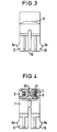
- Fig. 3 is a front elevation of the cap.
- Fig. 4 is a cap looking from the cable outlet side
- Fig. 5 shows the outlet end of the plug connector housing with the cap engaged, looking from the cable outlet side.
- Fig. 1 is a cross-section of a plug connector housing 1 having contact chambers to receive flat spring contacts (not shown) and a socket 3 for the beam waveguide plugs 4 of a beam waveguide cable 5.
- the plug connector housing 1 has a U-shaped channel 6, through which the cables are taken out of the plug housing.
- the U-shaped channel is closed by a snap cap 7.
- Cap 7 covers the rear zone of the housing from the beam waveguide cable socket as far as the output end of the U-shaped channel 6.
- the cap 7 has ducts 8 into which the beam waveguide cables 5 are inserted.
- the duct 8 is so shaped that the beam waveguide cable nowhere experiences a curvature of a radius below the minimum permissible radius of curvature for beam waveguide cables. This obviates any damage to the beam waveguide cable. Also, the duct 8 is so devised that an axial movement is possible damped by a silicone spring of the plug 4.
- the cap 7 is releasably secured by the engagement of detent lugs 9a, 9b in matching grooves in the housing 1.
- the cap 7 also shuts off the rear of the U-shaped channel 6 so that the metal cables (not shown) taken out of the plug connector housing 1 between the base 10 of the channel 6 and the underside of the cap 7 are pressed by webs 23, 24 at the base 18 and at the underside of the cap 7 in serpentine shape, thus ensuring that the metal cable is relieved of any appreciable tension.
- a cable bushing can follow this and prevent any bending of the bunch of cables where they are taken out of the housing 1 (not shown).
- Fig. 2 shows the cap 7 with one of its ducts 8 and the detent lugs 9a, 9b.
- Relatively sharp-edged pins 11 will be seen on the output side, in a staggered arrangement on the inner walls of the duct 8, and said pins engage in the sheath of the cable inserted in the duct 8 in order thus to relieve the cable of tension without damaging it.
- Shoulders 14 are also provided on the duct inlet 12 in order to clip the beam waveguide cable in on assembly. Radiused thickenings are provided at the duct outlet 13 and act as anti-bending means.
- Fig. 3 is a right-hand side elevation of the plug connector shown in Fig. 2. It will be seen that a slot 16 divides the right-hand end of the cap in Fig. 2 into two limbs 17, 18, on the outer ends of which each of the detent lugs 9a are disposed. The limbs thus become resilient so that the detent lugs can engage in correspondingly narrow grooves in the housing 1 and snap into corresponding seatings.
- the radiused shoulder 19 serves as a handle for pressing in the cap 7 and stabilises the spring action of the limbs 17, 18.
- Fig. 4 is an end plan view of the cap 7.
- the limbs 17, 18 will again be seen, together with the detent lugs 9a and the ducts 8 with beam waveguide cables 5 clamped between shoulders 14 by means of the pins 11.
- the ducts 8 are of U-shaped construction, the two openings of the U-shaped ducts each pointing to right and left and the two ducts 8 being connected by a web 20 in their bottom zone.
- Fig. 5 is a partial section and end elevation of the plug connector housing 1 with the cap 7 fitted.
- the U-shaped channel 6 will be seen partially in cross-section, and contains eight metal cables 21 in two layers each of four cables on the base of the U-shaped channel 6.
- the channel 6 is closed by the cap 7, which at the same time guides the metal cables 21 by its transverse webs 22 into the recess between the transverse web 22 and the base of the channel 6 serpentine-fashion, so that the metal cables are relieved of tension.
- the ducts 7 in the cap 7 each contain a beam waveguide cable 5.
- the ducts 8 are closed by the side walls of the U-shaped channel 6.
- the beam waveguide plugs 4 will be seen at the bottom end of the housing.
- the beam waveguide cables 5 and the metal cables 21 can be combined at the output side of the plug connector housing to form a composite cable and be interconnected by a common cover.
- An anti-bend bushing (not shown) can also be fitted in known manner at the end face of the U-shaped channel 6 and the cap 7.
- the plug connector housing combines two completely different tension relief means adapted to the specific requirements of the different cables and such means are both non-damaging and efficient, in the minimum space, any bending or curving of the beam waveguide cable with too small a radius of curvature, and the resulting attenuation losses, being reliably avoided.
- the cap is so constructed that the beam waveguide plug can move axially to allow for any tolerances. This ensures that the beam waveguide plugs always bear with light pressure on the opto-electronic components, so that again low attenuation is achieved.
- the bed waveguide cable additionally has anti-bending means in the cap. It is a simple matter to fit the cap, and this can be done without difficulty even in restricted space conditions.
Landscapes
- Physics & Mathematics (AREA)
- General Physics & Mathematics (AREA)
- Optics & Photonics (AREA)
- Mechanical Coupling Of Light Guides (AREA)
- Cable Accessories (AREA)
- Input Circuits Of Receivers And Coupling Of Receivers And Audio Equipment (AREA)
- Mechanical Light Control Or Optical Switches (AREA)
Abstract
Description
- This invention relates to a combined beam waveguide and metal cable plug connector in accordance with the preamble of claim 1.
- Plug connectors of this kind can be used wherever optical signal transmission and an electrical power supply are involved simultaneously. For example, in modern motor vehicles, the data transmission is by way of beam waveguides and the electrical power is fed to the loads via metal cables.
- The metal cables and the beam waveguide cables are taken out of the plug housing jointly at the back of the plug connector. In such cases, the electrical cable cores and the beam waveguide cables are frequently combined into a bunch and possibly surrounded by a common protective covering. In such cases there is a risk that despite their sensitivity to kinking and bending with too small a radius of curvature, the beam waveguide cables may undergo the same treatment as the metal cables, which are insensitive in this respect. A permanent or even just temporary curvature of the beam waveguide cables with too small a radius of curvature can permanently damage the beam waveguide fibres and result in excessive attenuation. This is particularly important if a 90° cable outlet is required.
- The object of this invention is to so to improve a combined beam waveguide and metal cable plug connector as to enable the beam waveguide cables together with the metal cables to be taken in defined manner laterally out of the plug housing with a high degree of relief from tension, while ensuring that the beam waveguide cables are so treated as to avoid any bends which cause attenuation. In addition, the beam waveguide plugs are to be axially movable in order to ensure permanent contact with the opto-electronic components despite tolerances.
- This problem is solved by the features of claim 1. Preferred embodiments of the present invention are indicated in the sub-claims.
- By means of the snap cap according to the invention, the beam waveguide cables have optimal guidance over the entire area of their change of direction within the plug housing so as reliably to avoid any bends.
- The metal cables and beam waveguide cables are combined at the outlet of the plug connector, from where the cable can be run on with substantially no appreciable abrupt changes of direction.
- The invention is explained in detail below with reference to one exemplified embodiment and the drawing wherein:
- Fig. 1 is a cross-section through a combined beam waveguide and metal cable plug connector according to the invention.
- Fig. 2 shows the snap cap according to Fig. 1.
- Fig. 3 is a front elevation of the cap.
- Fig. 4 is a cap looking from the cable outlet side and
- Fig. 5 shows the outlet end of the plug connector housing with the cap engaged, looking from the cable outlet side.
- Fig. 1 is a cross-section of a plug connector housing 1 having contact chambers to receive flat spring contacts (not shown) and a socket 3 for the beam waveguide plugs 4 of a
beam waveguide cable 5. At its connection side, the plug connector housing 1 has a U-shapedchannel 6, through which the cables are taken out of the plug housing. On the connection side of the plug connector housing 1 the U-shaped channel is closed by asnap cap 7.Cap 7 covers the rear zone of the housing from the beam waveguide cable socket as far as the output end of the U-shapedchannel 6. Thecap 7 hasducts 8 into which thebeam waveguide cables 5 are inserted. Theduct 8 is so shaped that the beam waveguide cable nowhere experiences a curvature of a radius below the minimum permissible radius of curvature for beam waveguide cables. This obviates any damage to the beam waveguide cable. Also, theduct 8 is so devised that an axial movement is possible damped by a silicone spring of the plug 4. - The
cap 7 is releasably secured by the engagement ofdetent lugs cap 7 also shuts off the rear of the U-shapedchannel 6 so that the metal cables (not shown) taken out of the plug connector housing 1 between thebase 10 of thechannel 6 and the underside of thecap 7 are pressed bywebs base 18 and at the underside of thecap 7 in serpentine shape, thus ensuring that the metal cable is relieved of any appreciable tension. A cable bushing can follow this and prevent any bending of the bunch of cables where they are taken out of the housing 1 (not shown). - Fig. 2 shows the
cap 7 with one of itsducts 8 and thedetent lugs duct 8, and said pins engage in the sheath of the cable inserted in theduct 8 in order thus to relieve the cable of tension without damaging it.Shoulders 14 are also provided on theduct inlet 12 in order to clip the beam waveguide cable in on assembly. Radiused thickenings are provided at theduct outlet 13 and act as anti-bending means. - Fig. 3 is a right-hand side elevation of the plug connector shown in Fig. 2. It will be seen that a
slot 16 divides the right-hand end of the cap in Fig. 2 into twolimbs detent lugs 9a are disposed. The limbs thus become resilient so that the detent lugs can engage in correspondingly narrow grooves in the housing 1 and snap into corresponding seatings. - The
radiused shoulder 19 serves as a handle for pressing in thecap 7 and stabilises the spring action of thelimbs - Fig. 4 is an end plan view of the
cap 7. Thelimbs detent lugs 9a and theducts 8 withbeam waveguide cables 5 clamped betweenshoulders 14 by means of the pins 11. Theducts 8 are of U-shaped construction, the two openings of the U-shaped ducts each pointing to right and left and the twoducts 8 being connected by aweb 20 in their bottom zone. - Fig. 5 is a partial section and end elevation of the plug connector housing 1 with the
cap 7 fitted. The U-shapedchannel 6 will be seen partially in cross-section, and contains eightmetal cables 21 in two layers each of four cables on the base of the U-shapedchannel 6. Thechannel 6 is closed by thecap 7, which at the same time guides themetal cables 21 by itstransverse webs 22 into the recess between thetransverse web 22 and the base of thechannel 6 serpentine-fashion, so that the metal cables are relieved of tension. Theducts 7 in thecap 7 each contain abeam waveguide cable 5. Theducts 8 are closed by the side walls of the U-shapedchannel 6. The beam waveguide plugs 4 will be seen at the bottom end of the housing. Thebeam waveguide cables 5 and themetal cables 21 can be combined at the output side of the plug connector housing to form a composite cable and be interconnected by a common cover. An anti-bend bushing (not shown) can also be fitted in known manner at the end face of the U-shapedchannel 6 and thecap 7. - The plug connector housing according to the invention combines two completely different tension relief means adapted to the specific requirements of the different cables and such means are both non-damaging and efficient, in the minimum space, any bending or curving of the beam waveguide cable with too small a radius of curvature, and the resulting attenuation losses, being reliably avoided. Advantageously, the cap is so constructed that the beam waveguide plug can move axially to allow for any tolerances. This ensures that the beam waveguide plugs always bear with light pressure on the opto-electronic components, so that again low attenuation is achieved. The bed waveguide cable additionally has anti-bending means in the cap. It is a simple matter to fit the cap, and this can be done without difficulty even in restricted space conditions. If the flat spring contacts have to be handled, it is possible to separate the
beam waveguide cables 5 together with thecap 7 without it being necessary to remove the cables from the cap. This also reduces any risk of damage in the event of repair or installation work. The general design of the plug connector housing is robust and reliable.
Claims (10)
- A combined optical fiber and metal cable plug connector with an angled cable outlet, comprising:characterized in thata housing (1) in whichoptical fiber plugs (4) and flat spring contacts are disposed in a front side of the housing in open chambers (2, 3) while an outlet for the metal cables (21) is provided in a rear side, opposite to the front side, of the housing; and a cap which fits into the rear side of the housingthe housing outlet for the metal cables comprises a channel (6) which opens towards the rear side of the housing, and whose base extends at an angle of not more than 90° to the plug axis,whereby the metal cables (21) can be taken out of the rear of the housing (1) in one or more layers on the channel base (6) in a direction perpendicular to the plug axis and,in that said cap (7), is constructed to snap fit into the rear side of the housing, thereby closing the channel (6) at the rear side of the housing and said cap has ducts (8) located on opposite sides of a portion of the cap that projects into the channel whereby the optical fibers (5) can be accommodated in the ducts (8), which each extend along a curved path thereby ensuring that the optical fibers (5) are bend through a radius which is non-damaging to the optical fibers.
- A combined optical fiber and metal cable plug connector according to claim 1, characterized in that the ducts (8) receive the optical fiber cables (5) directly at the rear side of the housing, the configuration of the ducts allowing axial movement of optical fiber plugs (4).
- A combined optical fiber and metal cable plug connector according to claim 1 or 2, characterized in that the cap (7) has a portion extending parallel to its snap-in direction having a slot (16) which divides its end facing the plugs into two limbs (17, 18), on each of the outsides of which are respectively disposed at least one detent lug (9a) which is adapted to engage in corresponding grooves in the housing (1).
- A combined optical fiber and metal cable plug connector according to any one of the preceding claims, characterized in that staggered sharp-edged retaining pins (11) project from the duct inner walls (8) in the region of the outlet end of the ducts (8) for engagement with the cable sheath (5) and a radiused constriction (15) is provided at the outlet to prevent. Sharp bending of the cable leaving the duct.
- A combined optical fiber and metal cable plug connector according to any one of the preceding claims, characterized in that the ducts (8) each have an U-shaped cross-section and the ducts get progressively narrower at the output end to clamp the beam waveguide cables (5).
- A combined optical fiber and metal cable plug connector according to any one of the preceding claims, characterized in that the cable outlet end of the cap (7) has a transverse web (22) by means of which the metal cables (21) are pressed on to the base of the U-shaped channel (6) when the cap is snap fitted into the housing.
- A combined optical fiber and metal cable plug connector according to any one of the preceding claims, characterized in that a strain relief boot is provided for the optical fiber cables (5) and the metal cables (21) at the outlet of the channel (6) and the cap (7).
- A combined optical fiber and metal cable plug connector according to any one of the preceding claims, characterized in that the connection between the housing (1) and cap (7) is by means of a snap-in connection means situated substantially on the axis of the beam waveguide plugs.
- A combined optical fiber and metal cable plug connector according to any one of the preceding claims, characterized in that the channel (6) is resilient in the region of the tension relief elements and the limbs (17, 18) are resilient in the region of the optical fiber plug (4).
- A combined optical fiber and metal cable plug connector according to any one of the preceding claims, characterized in that the cap (7) has resilient shoulders in the region of abutment of the optical fiber plug (4) in order to clamp the optical fiber cable in place on assembly.
Applications Claiming Priority (2)
| Application Number | Priority Date | Filing Date | Title |
|---|---|---|---|
| DE4412571A DE4412571C1 (en) | 1994-04-13 | 1994-04-13 | Combined optical waveguide metal cable plug-connector |
| DE4412571 | 1994-04-13 |
Publications (3)
| Publication Number | Publication Date |
|---|---|
| EP0677756A2 EP0677756A2 (en) | 1995-10-18 |
| EP0677756A3 EP0677756A3 (en) | 1996-05-01 |
| EP0677756B1 true EP0677756B1 (en) | 1999-07-14 |
Family
ID=6515190
Family Applications (1)
| Application Number | Title | Priority Date | Filing Date |
|---|---|---|---|
| EP95104212A Expired - Lifetime EP0677756B1 (en) | 1994-04-13 | 1995-03-22 | Combined beam waveguide and metal cable plug connector |
Country Status (6)
| Country | Link |
|---|---|
| US (1) | US5570443A (en) |
| EP (1) | EP0677756B1 (en) |
| AT (1) | ATE182220T1 (en) |
| CA (1) | CA2145341A1 (en) |
| DE (1) | DE4412571C1 (en) |
| ES (1) | ES2133607T3 (en) |
Families Citing this family (29)
| Publication number | Priority date | Publication date | Assignee | Title |
|---|---|---|---|---|
| DE4443200C1 (en) * | 1994-12-05 | 1996-06-20 | Framatome Connectors Int | Combined optical fibre cable and metal cable plug connector |
| US6017242A (en) * | 1995-06-05 | 2000-01-25 | Tensolite Company | Right-angled coaxial cable connector |
| DE29509629U1 (en) * | 1995-06-13 | 1995-08-24 | Abb Patent Gmbh, 68309 Mannheim | Device for transmitting the light emitted from a light source arranged inside a housing to the outside |
| DE19525739C1 (en) * | 1995-07-14 | 1996-10-02 | Framatome Connectors Int | Optical fibre plug connector |
| DE19531633A1 (en) * | 1995-08-28 | 1997-07-03 | Whitaker Corp | Optical data communication system |
| DE29708320U1 (en) * | 1997-05-09 | 1997-07-10 | Rehau Ag + Co, 95111 Rehau | Assembly aid |
| BR9906432A (en) | 1998-05-18 | 2000-07-25 | Sony Computer Entertainment Inc | External operating device and entertainment system |
| US6123568A (en) * | 1998-09-18 | 2000-09-26 | Curtis Computer Products, Inc. | Cable-orienting and space saving cable connector assembly |
| DE19945173B4 (en) * | 1998-09-22 | 2008-05-15 | The Whitaker Corp., Wilmington | Connector for at least one optical fiber cable |
| DE19845854C2 (en) * | 1998-10-05 | 2000-11-02 | Framatome Connectors Int | Optical fiber connector for a mechanically detachable connection between - at least one fiber optic connector pair - at least one fiber optic connector and a circuit board |
| JP2000258658A (en) * | 1999-03-09 | 2000-09-22 | Sony Corp | Plastic optical fiber connectors |
| DE19944060B4 (en) * | 1999-09-14 | 2008-04-03 | The Whitaker Corporation, Wilmington | Device for kink protection of optical cables |
| DE60144523D1 (en) | 2000-09-01 | 2011-06-09 | Tyco Electronics Amp Gmbh | CONNECTOR HOUSING WITH ANGLE PROTECTION |
| TW474464U (en) * | 2000-10-31 | 2002-01-21 | Hon Hai Prec Ind Co Ltd | Optoelectronic connector assembly |
| US6601997B2 (en) | 2001-04-17 | 2003-08-05 | Fci Americas Technology, Inc. | Fiber optic cable guide boot |
| JP2002341182A (en) * | 2001-05-14 | 2002-11-27 | Auto Network Gijutsu Kenkyusho:Kk | Optical connector |
| US6734435B2 (en) * | 2001-05-29 | 2004-05-11 | Rae Systems, Inc. | Photo-ionization detector and method for continuous operation and real-time self-cleaning |
| WO2002101436A1 (en) | 2001-06-12 | 2002-12-19 | Tyco Electronics Corporation | Integrated bend limiter for fiber optic connectors |
| CN1685253A (en) | 2001-06-26 | 2005-10-19 | Via系统集团公司 | Bending an optical fiber into backplane |
| US6629783B2 (en) | 2001-07-06 | 2003-10-07 | Fci Americas Technology, Inc. | Fiber optic cable guide boot |
| JP4197588B2 (en) | 2001-09-21 | 2008-12-17 | 旭硝子株式会社 | Assembly including plastic optical fiber outlet and plug |
| JP3805238B2 (en) * | 2001-11-26 | 2006-08-02 | 株式会社オートネットワーク技術研究所 | Optical connector |
| US6817780B2 (en) * | 2003-01-15 | 2004-11-16 | Fci Americas Technology, Inc. | Guide boot for a fiber-optic cable |
| GB0322893D0 (en) * | 2003-09-30 | 2003-10-29 | British Telecomm | Telecommunications lead in apparatus |
| WO2006019161A1 (en) * | 2004-08-20 | 2006-02-23 | Sumitomo Electric Industries, Ltd. | Optical connector and method of assembling optical connector |
| DE102006062695B4 (en) * | 2006-05-16 | 2008-05-08 | Roland Berger | Connector for an optical fiber |
| DE102012217211A1 (en) * | 2012-09-24 | 2014-03-27 | Tyco Electronics Amp Gmbh | Contact housing with positioning means for fixing the position of a kink-sensitive cable |
| CN110197977B (en) * | 2018-02-27 | 2021-05-18 | 中航光电科技股份有限公司 | Connectors and Connector Assemblies Using the Connectors |
| US20250199246A1 (en) * | 2023-12-19 | 2025-06-19 | Smiths Interconnect Canada Inc. | Systems and methods for vibration damping in multi-fiber connectors |
Family Cites Families (16)
| Publication number | Priority date | Publication date | Assignee | Title |
|---|---|---|---|---|
| US4203004A (en) * | 1978-04-20 | 1980-05-13 | Belden Corporation | Strain relief |
| US4325599A (en) * | 1979-12-05 | 1982-04-20 | Amp Incorporated | Phone plug |
| US4373777A (en) * | 1980-08-11 | 1983-02-15 | International Telephone And Telegraph Corporation | Connector and cable assembly |
| DE3113168C2 (en) * | 1981-04-01 | 1985-09-12 | Siemens AG, 1000 Berlin und 8000 München | Line connector for parallel optical data transmission |
| US4786136A (en) * | 1982-08-06 | 1988-11-22 | Iec Corporation | Optical fiber rotary coupler |
| US4611887A (en) * | 1983-02-24 | 1986-09-16 | Amp Incorporated | Fiber optic connector assembly and wall outlet thereof |
| US4767181A (en) * | 1983-11-17 | 1988-08-30 | American Telephone And Telegraph Company | Electrical/lightwave connection arrangement |
| JPS60107808U (en) * | 1983-12-27 | 1985-07-22 | デユポン ジヤパン リミテツド | Duplex connector for optical fiber |
| US4869686A (en) * | 1988-03-30 | 1989-09-26 | Molex Incorporated | Right angle electrical connector |
| US5185839A (en) * | 1988-09-09 | 1993-02-09 | Square D Company | Fiber optic cable receptacle |
| US5231685A (en) * | 1989-11-28 | 1993-07-27 | Kel Corporation | Multi-way electro-optic connector assemblies and optical fiber ferrule assemblies therefor |
| US5037175A (en) * | 1990-06-11 | 1991-08-06 | Amp Incorporated | Clip for dressing of fiber optic cable within confined space |
| US5109452A (en) * | 1990-07-16 | 1992-04-28 | Puritan-Bennett Corporation | Electrical-optical hybrid connector |
| US5073044A (en) * | 1990-10-31 | 1991-12-17 | Amp Incorporated | Right angle strain relief for optical fiber connector |
| IT1247307B (en) * | 1991-05-06 | 1994-12-12 | Sirti Spa | BRANCH DEVICE FOR OPTICAL FIBER CABLES |
| US5138678A (en) * | 1991-09-20 | 1992-08-11 | Briggs Robert C | Connector with a variable direction strain relief |
-
1994
- 1994-04-13 DE DE4412571A patent/DE4412571C1/en not_active Expired - Fee Related
-
1995
- 1995-03-22 ES ES95104212T patent/ES2133607T3/en not_active Expired - Lifetime
- 1995-03-22 EP EP95104212A patent/EP0677756B1/en not_active Expired - Lifetime
- 1995-03-22 AT AT95104212T patent/ATE182220T1/en not_active IP Right Cessation
- 1995-03-23 CA CA002145341A patent/CA2145341A1/en not_active Abandoned
- 1995-04-13 US US08/421,268 patent/US5570443A/en not_active Expired - Fee Related
Also Published As
| Publication number | Publication date |
|---|---|
| EP0677756A3 (en) | 1996-05-01 |
| ES2133607T3 (en) | 1999-09-16 |
| US5570443A (en) | 1996-10-29 |
| EP0677756A2 (en) | 1995-10-18 |
| CA2145341A1 (en) | 1995-10-14 |
| DE4412571C1 (en) | 1995-06-08 |
| ATE182220T1 (en) | 1999-07-15 |
Similar Documents
| Publication | Publication Date | Title |
|---|---|---|
| EP0677756B1 (en) | Combined beam waveguide and metal cable plug connector | |
| KR100248970B1 (en) | Adapter Assembly for Fiber Optic Connectors | |
| US6885805B2 (en) | Optical fiber guide device | |
| EP1122566B1 (en) | Fiber optic connection system | |
| US6134370A (en) | Fiber optic cable guide | |
| KR100248971B1 (en) | Adapter assembly for fiber optic connectors | |
| EP0837347B1 (en) | Fiber optic connector system | |
| JP4064784B2 (en) | Optical connector | |
| EP0788002A1 (en) | Fiber optic connector receptacle with protective shutter | |
| US5940560A (en) | Optical connection plug | |
| US6695490B2 (en) | Optical ring network, optical connector, and hybrid connector | |
| US6249635B1 (en) | Universal fiber optic splice holder | |
| EP1091223B1 (en) | Optical connector and an assembly method of optical plug | |
| US6945704B2 (en) | Optical connector | |
| US7490997B2 (en) | Integrated bend limiter for fiber optic connectors | |
| US6206580B1 (en) | Optical connector | |
| US6508594B1 (en) | Optical plug connector | |
| JP3765525B2 (en) | Optical connector | |
| US20010016102A1 (en) | Plug part for a combined optical and electrical plug-and-socket connection | |
| KR20220145160A (en) | Plug connector | |
| JP3756703B2 (en) | Optical connector | |
| JP3332642B2 (en) | Optical connector | |
| JP3896034B2 (en) | Optical connector | |
| US20260036762A1 (en) | Fiber optic adapter, protection unit, method for manufacturing a fiber optic adapter | |
| JP4064949B2 (en) | Embedded wall type optical fiber outlet device |
Legal Events
| Date | Code | Title | Description |
|---|---|---|---|
| PUAI | Public reference made under article 153(3) epc to a published international application that has entered the european phase |
Free format text: ORIGINAL CODE: 0009012 |
|
| AK | Designated contracting states |
Kind code of ref document: A2 Designated state(s): AT ES FR GB IT NL SE |
|
| PUAL | Search report despatched |
Free format text: ORIGINAL CODE: 0009013 |
|
| AK | Designated contracting states |
Kind code of ref document: A3 Designated state(s): AT ES FR GB IT NL SE |
|
| 17P | Request for examination filed |
Effective date: 19961014 |
|
| 17Q | First examination report despatched |
Effective date: 19970204 |
|
| GRAG | Despatch of communication of intention to grant |
Free format text: ORIGINAL CODE: EPIDOS AGRA |
|
| GRAG | Despatch of communication of intention to grant |
Free format text: ORIGINAL CODE: EPIDOS AGRA |
|
| GRAG | Despatch of communication of intention to grant |
Free format text: ORIGINAL CODE: EPIDOS AGRA |
|
| GRAH | Despatch of communication of intention to grant a patent |
Free format text: ORIGINAL CODE: EPIDOS IGRA |
|
| GRAH | Despatch of communication of intention to grant a patent |
Free format text: ORIGINAL CODE: EPIDOS IGRA |
|
| GRAA | (expected) grant |
Free format text: ORIGINAL CODE: 0009210 |
|
| AK | Designated contracting states |
Kind code of ref document: B1 Designated state(s): AT ES FR GB IT NL SE |
|
| REF | Corresponds to: |
Ref document number: 182220 Country of ref document: AT Date of ref document: 19990715 Kind code of ref document: T |
|
| ET | Fr: translation filed | ||
| REG | Reference to a national code |
Ref country code: ES Ref legal event code: FG2A Ref document number: 2133607 Country of ref document: ES Kind code of ref document: T3 |
|
| ITF | It: translation for a ep patent filed | ||
| PG25 | Lapsed in a contracting state [announced via postgrant information from national office to epo] |
Ref country code: SE Free format text: LAPSE BECAUSE OF NON-PAYMENT OF DUE FEES Effective date: 20000323 Ref country code: ES Free format text: LAPSE BECAUSE OF NON-PAYMENT OF DUE FEES Effective date: 20000323 |
|
| PLBE | No opposition filed within time limit |
Free format text: ORIGINAL CODE: 0009261 |
|
| STAA | Information on the status of an ep patent application or granted ep patent |
Free format text: STATUS: NO OPPOSITION FILED WITHIN TIME LIMIT |
|
| 26N | No opposition filed | ||
| PG25 | Lapsed in a contracting state [announced via postgrant information from national office to epo] |
Ref country code: NL Free format text: LAPSE BECAUSE OF NON-PAYMENT OF DUE FEES Effective date: 20001001 |
|
| EUG | Se: european patent has lapsed |
Ref document number: 95104212.6 |
|
| NLV4 | Nl: lapsed or anulled due to non-payment of the annual fee |
Effective date: 20001001 |
|
| PGFP | Annual fee paid to national office [announced via postgrant information from national office to epo] |
Ref country code: GB Payment date: 20010321 Year of fee payment: 7 |
|
| REG | Reference to a national code |
Ref country code: GB Ref legal event code: IF02 |
|
| PG25 | Lapsed in a contracting state [announced via postgrant information from national office to epo] |
Ref country code: GB Free format text: LAPSE BECAUSE OF NON-PAYMENT OF DUE FEES Effective date: 20020322 |
|
| GBPC | Gb: european patent ceased through non-payment of renewal fee |
Effective date: 20020322 |
|
| REG | Reference to a national code |
Ref country code: ES Ref legal event code: FD2A Effective date: 20010411 |
|
| PGFP | Annual fee paid to national office [announced via postgrant information from national office to epo] |
Ref country code: AT Payment date: 20050303 Year of fee payment: 11 |
|
| PG25 | Lapsed in a contracting state [announced via postgrant information from national office to epo] |
Ref country code: AT Free format text: LAPSE BECAUSE OF NON-PAYMENT OF DUE FEES Effective date: 20060322 |
|
| PGFP | Annual fee paid to national office [announced via postgrant information from national office to epo] |
Ref country code: IT Payment date: 20070611 Year of fee payment: 13 |
|
| PGFP | Annual fee paid to national office [announced via postgrant information from national office to epo] |
Ref country code: FR Payment date: 20070301 Year of fee payment: 13 |
|
| REG | Reference to a national code |
Ref country code: FR Ref legal event code: ST Effective date: 20081125 |
|
| PG25 | Lapsed in a contracting state [announced via postgrant information from national office to epo] |
Ref country code: FR Free format text: LAPSE BECAUSE OF NON-PAYMENT OF DUE FEES Effective date: 20080331 |
|
| PG25 | Lapsed in a contracting state [announced via postgrant information from national office to epo] |
Ref country code: IT Free format text: LAPSE BECAUSE OF NON-PAYMENT OF DUE FEES Effective date: 20080322 |