EP0677682A1 - Transmission with fixed transmission ratio - Google Patents
Transmission with fixed transmission ratio Download PDFInfo
- Publication number
- EP0677682A1 EP0677682A1 EP95200826A EP95200826A EP0677682A1 EP 0677682 A1 EP0677682 A1 EP 0677682A1 EP 95200826 A EP95200826 A EP 95200826A EP 95200826 A EP95200826 A EP 95200826A EP 0677682 A1 EP0677682 A1 EP 0677682A1
- Authority
- EP
- European Patent Office
- Prior art keywords
- transmission according
- belt
- pulley
- teeth
- tooth
- Prior art date
- Legal status (The legal status is an assumption and is not a legal conclusion. Google has not performed a legal analysis and makes no representation as to the accuracy of the status listed.)
- Granted
Links
- 230000005540 biological transmission Effects 0.000 title claims abstract description 41
- 239000002184 metal Substances 0.000 claims abstract description 6
- 230000013011 mating Effects 0.000 claims description 5
- 238000013016 damping Methods 0.000 claims description 3
- 230000000875 corresponding effect Effects 0.000 description 5
- 238000002485 combustion reaction Methods 0.000 description 4
- 230000000694 effects Effects 0.000 description 4
- 238000005452 bending Methods 0.000 description 3
- 239000000463 material Substances 0.000 description 3
- 230000007935 neutral effect Effects 0.000 description 3
- 230000009286 beneficial effect Effects 0.000 description 2
- 238000000034 method Methods 0.000 description 2
- 238000010276 construction Methods 0.000 description 1
- 238000006073 displacement reaction Methods 0.000 description 1
- 230000005489 elastic deformation Effects 0.000 description 1
- 238000004519 manufacturing process Methods 0.000 description 1
- 238000004806 packaging method and process Methods 0.000 description 1
- 230000002441 reversible effect Effects 0.000 description 1
- 230000000630 rising effect Effects 0.000 description 1
- 230000001360 synchronised effect Effects 0.000 description 1
Images


Classifications
-
- F—MECHANICAL ENGINEERING; LIGHTING; HEATING; WEAPONS; BLASTING
- F16—ENGINEERING ELEMENTS AND UNITS; GENERAL MEASURES FOR PRODUCING AND MAINTAINING EFFECTIVE FUNCTIONING OF MACHINES OR INSTALLATIONS; THERMAL INSULATION IN GENERAL
- F16H—GEARING
- F16H55/00—Elements with teeth or friction surfaces for conveying motion; Worms, pulleys or sheaves for gearing mechanisms
- F16H55/02—Toothed members; Worms
- F16H55/17—Toothed wheels
- F16H55/171—Toothed belt pulleys
-
- F—MECHANICAL ENGINEERING; LIGHTING; HEATING; WEAPONS; BLASTING
- F16—ENGINEERING ELEMENTS AND UNITS; GENERAL MEASURES FOR PRODUCING AND MAINTAINING EFFECTIVE FUNCTIONING OF MACHINES OR INSTALLATIONS; THERMAL INSULATION IN GENERAL
- F16G—BELTS, CABLES, OR ROPES, PREDOMINANTLY USED FOR DRIVING PURPOSES; CHAINS; FITTINGS PREDOMINANTLY USED THEREFOR
- F16G1/00—Driving-belts
- F16G1/28—Driving-belts with a contact surface of special shape, e.g. toothed
-
- F—MECHANICAL ENGINEERING; LIGHTING; HEATING; WEAPONS; BLASTING
- F16—ENGINEERING ELEMENTS AND UNITS; GENERAL MEASURES FOR PRODUCING AND MAINTAINING EFFECTIVE FUNCTIONING OF MACHINES OR INSTALLATIONS; THERMAL INSULATION IN GENERAL
- F16H—GEARING
- F16H7/00—Gearings for conveying rotary motion by endless flexible members
- F16H7/02—Gearings for conveying rotary motion by endless flexible members with belts; with V-belts
- F16H7/023—Gearings for conveying rotary motion by endless flexible members with belts; with V-belts with belts having a toothed contact surface or regularly spaced bosses or hollows for slipless or nearly slipless meshing with complementary profiled contact surface of a pulley
Definitions
- the invention relates to a transmission with a fixed transmission ratio, comprising a pliable endless member which is provided with a profile of mainly transversely oriented teeth, and at least two pulleys which are each provided, on their circumferential surface, with recesses which mate with the teeth.
- Such transmissions are generally known. Examples to be mentioned are the use in packaging machines, production machines and the like. In internal combustion engines, too, such a transmission is found between the crankshaft and the camshaft to operate the valves.
- the cost price of a chain transmission is fairly high.
- the chain transmission has an uneven character, caused by the polygon effect which is associated with the pitch length of the chain links. Moreover, after some time wear occurs in the chain and as a consequence correct synchronization is lost.
- the object of the invention is to provide a transmission which lacks these drawbacks.
- This object is achieved by the pliable member being a flexible belt which is stiff in its longitudinal direction.
- a belt may, for example, be made of metal; the thickness of the belt is then preferably considerably smaller than its width.
- the teeth may be formed so as to be integral with the belt.
- a further important advantage is that, given a limited width of the grooves in the pulleys, virtually no polygon effect arises, which makes it possible to ensure very smooth running.
- the synchronous action of the belt is, moreover, positively affected by its high degree of stiffness with respect to tensile forces. Because of the positive synchronization by means of the teeth and grooves mating and the high degree of stiffness of the belt, it is, moreover, possible to limit the pretension in the belt, low loads on shafts and bearings thus being achieved.
- the teeth on the belt mate with the grooves in the pulleys.
- the thickness of the teeth is preferably smaller than the width of the recesses.
- the belt is positioned around the pulleys with a certain pretension.
- This pretension can, for example, be adjusted by means of a tensioning mechanism which is known per se. Because of this pretension, the belt is able to transmit, by friction, a couple to the pulleys. In the applications intended for the present transmission, where the belt is generally in an oil-lubricated environment, the couple to be transmitted will, however, be considerably greater than this frictional couple. This means that the belt will slip until a flank of one of the teeth comes into contact with the facing flank of the groove in which that tooth is situated.
- the pitch of the recesses of the driving pulley is greater than the tooth pitch
- the pitch of the recesses of the driven pulley is smaller than the tooth pitch.
- the tooth just moving into a recess lands in the foremost part of the recess, as seen in the direction of revolution of the pulley.
- the tooth which, on the other side, is almost moving out of its recess is, however, in a position completely shifted to the rear, against the flank of the recess.
- This tooth and recess form the only pair whose flanks are in contact with each other and therefore it is only this pair which determines the position of the belt and the driving pulley with respect to each other.
- the reverse effect occurs.
- the tooth just moving into a recess lands in the rearmost portion of the latter, while said tooth, as it continues its path with the co-rotating pulley, is continually shifted slightly further forwards, each time the tooth moves out of its recess.
- the position of the pulley with respect to the belt is determined solely by the single, foremost pair (i.e. the pair whose tooth is almost moving out of its recess) whose flanks are touching one another.
- the belt may have a tapered thickness, such that at the position of each tooth the thickness is relatively large and in areas in between two teeth the thickness is relatively small. With such a design, the belt may be subjected to relatively pronounced bending, so that it is suitable for small pulleys without the stresses in the material in the belt becoming too high.
- the profile of the thickness of the belt is symmetric with respect to a centre plane of the belt. This causes the belt, over its straight section, to be pulled into a straight shape and unnecessary bending stresses are avoided.
- the position of the teeth of the relatively thick portions of the belt has the advantage that the teeth can be supported effectively without the risk of their tilting under the influence of forces exerted thereon by the pulley, as a result of which the tilting forces are absorbed in the tooth-supported portion of the belt without the stresses in the material becoming excessively large.
- Each tooth and recess may have an asymmetric cross-sectional shape, so that, as it moves into or out of the recess, the free tooth flank does not come into contact with the flank of the corresponding recess.
- each pulley may be provided with damping means to suppress vibrations which are generated by mating between teeth and recesses.
- one flank of each recess may be designed so as to be resilient.
- two incisions are provided at the location of each cutout, one of which opens into the bottom of the cutout and the other at the periphery of the pulley in the vicinity of the cutout.
- each pulley may have alternating areas, in the circumferential direction, having a relatively high curvature and a relatively low curvature.
- the areas having a relatively high curvature are situated between two grooves each.
- This design is beneficial when a belt having a tapered thickness as described above is used. Those areas of the belt which have the smallest thickness are then situated at the location of those parts of the circumference of the pulley which have the smallest radius of curvature.
- the relatively thick parts of the belt, where a tooth is situated need curve less, since they are situated at the location of those parts of the circumference which have a relatively large radius of curvature.
- the transmission according to the invention can function both in an oil bath and in a dry environment.
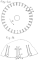
- the transmission depicted in Figure 1 comprises a pliable metal belt 1, a driving pulley 2 and a driven pulley 3.
- This transmission may, for example, form the link between the crankshaft and the camshaft of an internal combustion engine.
- the metal belt 1 is positioned round the pulleys 2 and 3 at a certain pretension.
- This pretension can be obtained, for example, by means of a pretensioning device (not shown) which is known per se and which, for example, is held in position so as to press against the outside of the non-pulling part of the belt 1.
- a frictional couple can be transmitted. This frictional couple is not sufficiently large, however, to provide the transmission between the pulleys 2, 3.
- teeth 4 are employed on the belt 1, on the one hand, whilst, on the other hand, recesses are employed, in the pulleys 2 and 3, which take the form of transversely running grooves 5 and 6, respectively.
- the pitch of the teeth 4 on the belt 1 is chosen in such a way that it is smaller than the pitch of the grooves 5 in the driving pulley 2, but greater than the pitch of the grooves 6 in the driven pulley 3.
- the result of this is that, in the case of a tooth 7 which has just moved into a groove 8 of the driven pulley 3, the tooth 7 is situated, in terms of the direction of revolution (as indicated by the arrow 9) of the driven pulley 3, in the rear of the groove 8.
- the tooth 10 leaves its groove 11, which results in the tooth situated behind it pushing forward, as seen in the direction of revolution 9, as a result of which it in turn comes to lie against the associated flank of the groove in which it is situated.
- the belt 1 in its entirety slips over the circumference of the driven pulley 3 and all the teeth 4 likewise slip over that distance in their corresponding groove.
- Figure 2 shows an illustrative embodiment of a belt provided with teeth 4.
- the belt has thickened portions 23 at the location of the teeth 4 and thinner portions 24 in the areas between the teeth 4.
- the advantage of this embodiment is that, on the one hand, the teeth 4 are supported effectively, in such a way that they cannot tilt under the influence of the driving forces, whilst, on the other hand, the belt has adequate flexibility thanks to the thinner portions 24.
- the belt with the exception of the teeth 4, is of symmetric design, which means that in the straight parts of the belt the neutral line 25 is a straight line, as a result of which unnecessary bending stresses are avoided.
- the illustrative embodiment of Figure 3 likewise shows a belt having teeth 4, thicker portions 23 and thinner portions 24.
- the neutral line 26 in the right parts is not a straight line, however. In some cases it may be beneficial to choose a neutral line of this type, such a line, after all, having a straightening effect on the belt in the right parts under the tensile force.
- the teeth 4 may be disposed both on the straight side of the belt and on the side having the tapered thickness.
- Figures 4 and 5 depict an example for a driven pulley having grooves 27, a radial incision 28 opening in the bottom of each groove. At some distance, in the direction of revolution 29 for the groove 27, a second radial incision 30 opens out. Both incisions 28, 30 cause the flank 31 of groove 27 to be elastically displaceable to a small extent, in the circumferential direction of the pulley. Such an elastic displaceability provides a damping effect for the contact forces which arise whenever a tooth flank 12 comes into contact with the groove flank 31, as can be seen, for example, in Figure 1d.
- Figure 4b depicts an example of a pulley in which the pulley has alternating areas, in the circumferential direction, having a relatively small radius of curvature and a relatively large radius of curvature.
- the areas having a relatively small radius of curvature are situated in each case between two recesses 27.
- the relatively thick portions of the belt, in which the teeth are situated being situated at the location of those parts of the circumference which have a relatively large radius of curvature, they will bend less. If a belt having a tapered thickness, as described above, is used on such a pulley, this prevents the tensions in the material in the belt from rising to a high level.
- the elastic displacement of tooth flank 31 can further be influenced by providing, in the incision 30, a circular enlargement 32 with an elastic member 33 therein.
Abstract
Description
- The invention relates to a transmission with a fixed transmission ratio, comprising a pliable endless member which is provided with a profile of mainly transversely oriented teeth, and at least two pulleys which are each provided, on their circumferential surface, with recesses which mate with the teeth.
- Such transmissions are generally known. Examples to be mentioned are the use in packaging machines, production machines and the like. In internal combustion engines, too, such a transmission is found between the crankshaft and the camshaft to operate the valves.
- With the latter application, in particular, various designs are known, such as a chain with chain wheels or a plastic toothed belt with associated toothed wheels. All these known constructions have certain drawbacks, however.
- Thus the cost price of a chain transmission is fairly high. In addition, the chain transmission has an uneven character, caused by the polygon effect which is associated with the pitch length of the chain links. Moreover, after some time wear occurs in the chain and as a consequence correct synchronization is lost.
- Drawbacks of the plastic toothed belt are the poor synchronization and the short service life. Since it cannot be readily predicted when such toothed belts will fail, relatively short replacement periods must be observed.
- The object of the invention is to provide a transmission which lacks these drawbacks. This object is achieved by the pliable member being a flexible belt which is stiff in its longitudinal direction. Such a belt may, for example, be made of metal; the thickness of the belt is then preferably considerably smaller than its width. The teeth may be formed so as to be integral with the belt.
- The advantage of a flexible metal belt is that no wear is possible therein, since only elastic deformations take place. Moreover, such a belt readily withstands high temperatures, for example those prevailing in an internal combustion engine. Consequently, a long service life can be guaranteed.
- A further important advantage is that, given a limited width of the grooves in the pulleys, virtually no polygon effect arises, which makes it possible to ensure very smooth running. The synchronous action of the belt is, moreover, positively affected by its high degree of stiffness with respect to tensile forces. Because of the positive synchronization by means of the teeth and grooves mating and the high degree of stiffness of the belt, it is, moreover, possible to limit the pretension in the belt, low loads on shafts and bearings thus being achieved.
- As mentioned earlier, the teeth on the belt mate with the grooves in the pulleys. To avoid said teeth and grooves having to meet unduly narrow tolerances, the thickness of the teeth, as seen in the driving direction, is preferably smaller than the width of the recesses. Thus it is possible to ensure that the run-in of the teeth into the grooves becomes insensitive to variations in the tooth pitch and in the pitch of the recesses.
- In spite of this difference in the dimensions of teeth and grooves it is nevertheless possible to achieve exact synchronization of the pulley rotations, for the reasons set out below.
- The belt is positioned around the pulleys with a certain pretension. This pretension can, for example, be adjusted by means of a tensioning mechanism which is known per se. Because of this pretension, the belt is able to transmit, by friction, a couple to the pulleys. In the applications intended for the present transmission, where the belt is generally in an oil-lubricated environment, the couple to be transmitted will, however, be considerably greater than this frictional couple. This means that the belt will slip until a flank of one of the teeth comes into contact with the facing flank of the groove in which that tooth is situated.
- In connection therewith, the pitch of the recesses of the driving pulley is greater than the tooth pitch, and the pitch of the recesses of the driven pulley is smaller than the tooth pitch. For the driving pulley this means that the tooth just moving into a recess lands in the foremost part of the recess, as seen in the direction of revolution of the pulley. The tooth which, on the other side, is almost moving out of its recess is, however, in a position completely shifted to the rear, against the flank of the recess. This tooth and recess form the only pair whose flanks are in contact with each other and therefore it is only this pair which determines the position of the belt and the driving pulley with respect to each other.
- It should further be borne in mind that, as said tooth moves out of its recess, the mating between said flanks is lost. At that instant, the belt slips to the rear over a tiny distance, this being the difference in the pitch of the belt and the driving pulley, as seen in the direction of revolution of the driving pulley, as a result of which the flanks of the next pair comprising a tooth and recess will mate. This tiny slip, which is possible because the driving couple is greater than the frictional couple, affects all the teeth, so that each tooth, when the foremost tooth disengages, is shifted slightly further backwards with respect to its recess.
- In the case of the driven pulley and the belt, the reverse effect occurs. There, the tooth just moving into a recess lands in the rearmost portion of the latter, while said tooth, as it continues its path with the co-rotating pulley, is continually shifted slightly further forwards, each time the tooth moves out of its recess. Here, again, the position of the pulley with respect to the belt is determined solely by the single, foremost pair (i.e. the pair whose tooth is almost moving out of its recess) whose flanks are touching one another.
- The belt may have a tapered thickness, such that at the position of each tooth the thickness is relatively large and in areas in between two teeth the thickness is relatively small. With such a design, the belt may be subjected to relatively pronounced bending, so that it is suitable for small pulleys without the stresses in the material in the belt becoming too high.
- Preferably, the profile of the thickness of the belt is symmetric with respect to a centre plane of the belt. This causes the belt, over its straight section, to be pulled into a straight shape and unnecessary bending stresses are avoided.
- The position of the teeth of the relatively thick portions of the belt has the advantage that the teeth can be supported effectively without the risk of their tilting under the influence of forces exerted thereon by the pulley, as a result of which the tilting forces are absorbed in the tooth-supported portion of the belt without the stresses in the material becoming excessively large.
- Each tooth and recess may have an asymmetric cross-sectional shape, so that, as it moves into or out of the recess, the free tooth flank does not come into contact with the flank of the corresponding recess.
- In order to prevent the transmission from starting to vibrate at its natural frequency as a result of the contact forces between teeth and recesses, each pulley may be provided with damping means to suppress vibrations which are generated by mating between teeth and recesses. An advantage of this design is also that, thanks to the resilient characteristics of the flanks of the recesses, a plurality of teeth simultaneously, for example two or three, can mate with the pulley in question. As a result, better transfer of force is obtained, while at the same time the engagement or disengagement of teeth and recesses can proceed more smoothly. Furthermore, reduced wear of teeth and recesses is thus possible, which affords a longer service life.
- In that connection, one flank of each recess may be designed so as to be resilient. According to a practical embodiment, in this case two incisions are provided at the location of each cutout, one of which opens into the bottom of the cutout and the other at the periphery of the pulley in the vicinity of the cutout.
- These incisions may run radially, while the incision opening at the periphery of the pulley may have a resilient element provided therein.
- Further, each pulley may have alternating areas, in the circumferential direction, having a relatively high curvature and a relatively low curvature. In particular, the areas having a relatively high curvature are situated between two grooves each. This design is beneficial when a belt having a tapered thickness as described above is used. Those areas of the belt which have the smallest thickness are then situated at the location of those parts of the circumference of the pulley which have the smallest radius of curvature. The relatively thick parts of the belt, where a tooth is situated, need curve less, since they are situated at the location of those parts of the circumference which have a relatively large radius of curvature.
- It should be noted that the transmission according to the invention can function both in an oil bath and in a dry environment.
- An illustrative embodiment of a transmission according to the invention will now be explained in more detail with reference to the figures.
- Figures 1 and 1a to 1e inclusive show a partial side-view, including details, of the transmission.
- Figure 2 shows a detail of a first embodiment of the belt which forms part of the transmission.
- Figure 3 shows a second embodiment of a belt.
- Figure 4a, b shows a possible embodiment of a pulley.
- Figure 5 shows a magnified detail of the pulley according to Figure 4.
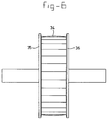
- Figure 6 shows a view of a pulley.
- The transmission depicted in Figure 1 comprises a
pliable metal belt 1, a drivingpulley 2 and a drivenpulley 3. This transmission may, for example, form the link between the crankshaft and the camshaft of an internal combustion engine. - The
metal belt 1 is positioned round thepulleys belt 1. By means of this frictional mating between thepulleys pulleys - To achieve correct synchronization between the two
pulleys teeth 4 are employed on thebelt 1, on the one hand, whilst, on the other hand, recesses are employed, in thepulleys grooves - The pitch of the
teeth 4 on thebelt 1 is chosen in such a way that it is smaller than the pitch of thegrooves 5 in the drivingpulley 2, but greater than the pitch of thegrooves 6 in the drivenpulley 3. The result of this is that, in the case of atooth 7 which has just moved into agroove 8 of the drivenpulley 3, thetooth 7 is situated, in terms of the direction of revolution (as indicated by the arrow 9) of the drivenpulley 3, in the rear of thegroove 8. In this context, refer to detail A of Figure 1 and to Figure 1a. - On that side of the driven
pulley 3, which is situated roughly diametrically opposite, in this context refer to detail D of Figure 1 and to Figure 1d, thetooth 10 has been pushed completely forwards in that direction into the correspondinggroove 11. Theflanks tooth 10 and agroove 11 forms the only pair of the teeth and the grooves ofbelt 1 and drivenpulley 3 which has mated. Thistooth 10 andgroove 11 are therefore responsible for the correct position of thebelt 1 with respect to the drivenpulley 3, in other words they afford the synchronizing action of said two parts. - When the driven
pulley 3 has rotated slightly further, thetooth 10 leaves itsgroove 11, which results in the tooth situated behind it pushing forward, as seen in the direction of revolution 9, as a result of which it in turn comes to lie against the associated flank of the groove in which it is situated. In the process, thebelt 1 in its entirety slips over the circumference of the drivenpulley 3 and all theteeth 4 likewise slip over that distance in their corresponding groove. - The result of all these successive small slips is that the
teeth 4 move continually further forward in theircorresponding groove 5. In detail C of Figure 1, and Figure 1c, it can be seen that thetooth 14 has been pushed forward in thegroove 15 over approximately half the width of the latter. - A corresponding effect arises in the driving
pulley 2, except that atooth 17, which has just entered thegroove 16, of thebelt 1 is now situated in a forward position in thatgroove 16, in terms of the direction of revolution (indicated by arrow 18) ofpulley 2. On the diametrically approximately opposite side, thetooth 19 has been pushed completely backwards in itsgroove 20, as a result of whichtooth flank 21 has come into contact with therearmost groove flank 22. Thispair comprising tooth 19 andgroove 20 is the only one whose flanks have mated; saidpair belt 1 with respect to the drivingpulley 2, in other words this pair provides the correct synchronization. - Here again it is the case that, as the
foremost tooth 19, as seen in the direction ofrevolution 18, leaves itsgroove 20, thebelt 1 slips with respect to the drivingpulley 2, but now in a backward direction. In the process, the tooth and groove which subsequently act as the foremost pair come into contact with each other via their flanks. - In Figures 1a to 1e inclusive, in each case the
foremost flank 12 of the teeth is positioned more obliquely than therearmost flank 21. Such a shape has the advantage that the teeth, as they leave the groove of the driven pulley, no longer come into contact with theforemost groove flank 13 of thegrooves 6 of the drivenpulley 3. - Figure 2 shows an illustrative embodiment of a belt provided with
teeth 4. The belt has thickenedportions 23 at the location of theteeth 4 andthinner portions 24 in the areas between theteeth 4. The advantage of this embodiment is that, on the one hand, theteeth 4 are supported effectively, in such a way that they cannot tilt under the influence of the driving forces, whilst, on the other hand, the belt has adequate flexibility thanks to thethinner portions 24. - In Figure 2, the belt, with the exception of the
teeth 4, is of symmetric design, which means that in the straight parts of the belt theneutral line 25 is a straight line, as a result of which unnecessary bending stresses are avoided. - The illustrative embodiment of Figure 3 likewise shows a
belt having teeth 4,thicker portions 23 andthinner portions 24. In this embodiment, theneutral line 26 in the right parts is not a straight line, however. In some cases it may be beneficial to choose a neutral line of this type, such a line, after all, having a straightening effect on the belt in the right parts under the tensile force. Theteeth 4 may be disposed both on the straight side of the belt and on the side having the tapered thickness. - Figures 4 and 5 depict an example for a driven
pulley having grooves 27, aradial incision 28 opening in the bottom of each groove. At some distance, in the direction ofrevolution 29 for thegroove 27, a secondradial incision 30 opens out. Bothincisions flank 31 ofgroove 27 to be elastically displaceable to a small extent, in the circumferential direction of the pulley. Such an elastic displaceability provides a damping effect for the contact forces which arise whenever atooth flank 12 comes into contact with thegroove flank 31, as can be seen, for example, in Figure 1d. - Figure 4b depicts an example of a pulley in which the pulley has alternating areas, in the circumferential direction, having a relatively small radius of curvature and a relatively large radius of curvature. In this arrangement, the areas having a relatively small radius of curvature are situated in each case between two
recesses 27. As a result of the relatively thick portions of the belt, in which the teeth are situated, being situated at the location of those parts of the circumference which have a relatively large radius of curvature, they will bend less. If a belt having a tapered thickness, as described above, is used on such a pulley, this prevents the tensions in the material in the belt from rising to a high level. - The elastic displacement of
tooth flank 31 can further be influenced by providing, in theincision 30, acircular enlargement 32 with anelastic member 33 therein. - In the view of Figure 6 it can be seen that the
circumference 34 of the pulley is curved in a radial plane. This curvature has the advantage that the belt centres itself on that circumferential surface. At the same time, guideflanges
Claims (20)
- Transmission with a fixed transmission ratio, comprising a pliable endless member which is provided with a profile of mainly transversely oriented teeth, and at least two pulleys which are each provided, on their circumferential surface, with recesses which mate with the teeth, characterized in that the pliable member is a flexible belt which is stiff in its longitudinal direction.
- Transmission according to Claim 1, wherein the belt is made of metal.
- Transmission according to Claim 1 or 2, wherein the thickness of the belt is considerably smaller than its width.
- Transmission according to Claim 1, 2 or 3, wherein the teeth are formed so as to be integral with the belt.
- Transmission according to any one of the preceding claims, wherein the thickness of the teeth, as seen in the driving direction, is smaller than the width of the recesses.
- Transmission according to any one of the preceding claims, wherein the pitch of the recesses of the driving pulley is greater than the tooth pitch, and the pitch of the recesses of the driven pulley is smaller than the tooth pitch.
- Transmission according to any one of the preceding claims, wherein the width of the recesses depends on the number of teeth in engagement with the pulley and the pitch difference between the pulley and the belt.
- Transmission according to any one of the preceding claims, wherein the belt has a tapered thickness, such that at the location of each tooth the thickness is relatively large and in areas in between two teeth the thickness is relatively small.
- Transmission according to Claim 8, wherein the profile of the thickness of the belt is symmetric with respect to a centre plane of the belt.
- Transmission according to any one of the preceding claims, wherein each tooth and recess have an asymmetric cross-sectional shape.
- Transmission according to Claim 10, wherein, as seen in the driving direction, the foremost and/or rearmost flank of each tooth is chamfered.
- Transmission according to any one of the preceding claims, wherein each pulley is provided with damping means to suppress vibrations which are generated by mating between teeth and recesses.
- Transmission according to Claim 12, wherein one flank of each recess is designed so as to be resilient.
- Transmission according to Claim 13, wherein two incisions are provided at the location of each cutout, one of which opens into the bottom of the cutout and the other at the periphery of the pulley in the vicinity of the cutout.
- Transmission according to Claim 14, wherein the incisions run radially.
- Transmission according to Claim 14 or 15, wherein the incision opening out at the periphery of the pulley has a resilient element provided therein.
- Transmission according to any one of Claims 12-16, wherein each pulley has alternating areas, in the circumferential direction, having a relatively high curvature and a relatively low curvature.
- Transmission according to Claim 17, wherein the areas having a relatively high curvature are situated between two grooves each.
- Transmission according to any one of Claims 12-18, wherein the perimeter of each pulley has a convex curvature in a radial plane.
- Transmission according to any one of Claims 11-19, wherein each pulley on both sides has guide flanges.
Applications Claiming Priority (2)
| Application Number | Priority Date | Filing Date | Title |
|---|---|---|---|
| NL9400586 | 1994-04-13 | ||
| NL9400586A NL9400586A (en) | 1994-04-13 | 1994-04-13 | Fixed gear ratio gearbox. |
Publications (2)
| Publication Number | Publication Date |
|---|---|
| EP0677682A1 true EP0677682A1 (en) | 1995-10-18 |
| EP0677682B1 EP0677682B1 (en) | 1998-06-03 |
Family
ID=19864062
Family Applications (1)
| Application Number | Title | Priority Date | Filing Date |
|---|---|---|---|
| EP95200826A Expired - Lifetime EP0677682B1 (en) | 1994-04-13 | 1995-03-31 | Transmission with fixed transmission ratio |
Country Status (7)
| Country | Link |
|---|---|
| US (1) | US5662541A (en) |
| EP (1) | EP0677682B1 (en) |
| JP (1) | JPH0842645A (en) |
| KR (1) | KR950033180A (en) |
| DE (1) | DE69502764D1 (en) |
| NL (1) | NL9400586A (en) |
| RU (1) | RU95105431A (en) |
Cited By (3)
| Publication number | Priority date | Publication date | Assignee | Title |
|---|---|---|---|---|
| EP2162637A2 (en) * | 2007-05-31 | 2010-03-17 | Henry D. Bronson | Reciprocating belt drive |
| US10716912B2 (en) | 2015-03-31 | 2020-07-21 | Fisher & Paykel Healthcare Limited | User interface and system for supplying gases to an airway |
| US11324908B2 (en) | 2016-08-11 | 2022-05-10 | Fisher & Paykel Healthcare Limited | Collapsible conduit, patient interface and headgear connector |
Families Citing this family (21)
| Publication number | Priority date | Publication date | Assignee | Title |
|---|---|---|---|---|
| US5957797A (en) * | 1996-09-04 | 1999-09-28 | Wright State University | Automatic change transmission utilizing continuous elastic drive belt and method |
| US6135907A (en) * | 1996-09-04 | 2000-10-24 | The Trustees Of Columbia University In The City Of New York | Apparatus and method for automatic speed change transmission utilizing continuous elastic drive belt of high elongability |
| US5984816A (en) * | 1997-06-27 | 1999-11-16 | Mitsuboshi Belting Ltd. | Toothed power transmission belt and drive system using the power transmission belt |
| US7210573B2 (en) * | 2002-03-05 | 2007-05-01 | Thermodrive Llc | Conveyor belt |
| US20050255953A1 (en) * | 2004-05-12 | 2005-11-17 | Timothy Puckett | Band Drive System for Telescopes, LIDAR and Other Instruments |
| US8668422B2 (en) * | 2004-08-17 | 2014-03-11 | Mattson Technology, Inc. | Low cost high throughput processing platform |
| US20060154766A1 (en) * | 2005-01-10 | 2006-07-13 | Fraser Lacy | Belt drive system |
| PL1838600T3 (en) * | 2005-01-19 | 2012-01-31 | Thermodrive Llc | Low friction, direct drive conveyor belt |
| US8464862B2 (en) * | 2006-01-31 | 2013-06-18 | Thermodrive, Llc | Conveyor with troughed low friction, positive drive belt |
| DK1979652T3 (en) * | 2006-02-02 | 2012-09-10 | Thermodrive Llc | Low friction, directly driven conveyor with bevel gear |
| US20090000852A1 (en) * | 2007-06-29 | 2009-01-01 | Gm Global Technology Operations, Inc. | Silent Chain with Asymmetric Involute Profile |
| US8276747B2 (en) * | 2007-06-29 | 2012-10-02 | Habasit Ag | Module for a modular belt and a driving sprocket for easy cleaning |
| US8544637B2 (en) * | 2007-07-10 | 2013-10-01 | Habasit Ag | Continuous conveyor belt |
| US9541173B2 (en) * | 2014-09-18 | 2017-01-10 | Gates Corporation | Belt drive with compression span |
| US9528584B2 (en) * | 2015-05-14 | 2016-12-27 | Gates Corporation | Belt drive mechanism |
| KR101866013B1 (en) * | 2016-03-16 | 2018-06-08 | 현대자동차주식회사 | Decreasing Tension type Timing Belt and Timing System thereof |
| DE202016001776U1 (en) * | 2016-03-18 | 2017-06-21 | Gebr. Bode Gmbh & Co. Kg | Timing belt drive with power drivers |
| JP6773969B2 (en) * | 2016-09-02 | 2020-10-21 | 株式会社椿本チエイン | Chain transmission mechanism |
| JP6829388B2 (en) * | 2017-02-27 | 2021-02-10 | 株式会社椿本チエイン | Toothed belt transmission device |
| US10577051B2 (en) * | 2017-09-15 | 2020-03-03 | Shimano Inc. | Bicycle sprocket |
| RU2761154C1 (en) * | 2020-08-28 | 2021-12-06 | Сергей Владимирович Воронцов | Roller-based modular veneer dryer |
Citations (6)
| Publication number | Priority date | Publication date | Assignee | Title |
|---|---|---|---|---|
| US2718790A (en) * | 1954-09-29 | 1955-09-27 | Eastman Kodak Co | Power transmission mechanism |
| DE1112362B (en) * | 1956-02-23 | 1961-08-03 | Wilhelm Herm Mueller & Co K G | Toothed belt drive |
| FR2089985A5 (en) * | 1970-04-21 | 1972-01-07 | Fiat Spa | |
| US4047444A (en) * | 1976-09-10 | 1977-09-13 | Borg-Warner Corporation | Synchronous belt and pulley drive |
| EP0405667A1 (en) * | 1989-06-30 | 1991-01-02 | Koninklijke Philips Electronics N.V. | Transmission system, motor drive comprising such a transmission system and wheel for such a transmission system or motor drive |
| DE9403404U1 (en) * | 1993-04-21 | 1994-04-28 | Zeller Hans | Drive arrangement |
Family Cites Families (5)
| Publication number | Priority date | Publication date | Assignee | Title |
|---|---|---|---|---|
| US3504562A (en) * | 1968-10-31 | 1970-04-07 | Us Army | Cushioned tooth sprocket wheel |
| US3597985A (en) * | 1970-02-05 | 1971-08-10 | Borg Warner | Flexible power transmission drive |
| US4147069A (en) * | 1976-10-01 | 1979-04-03 | Fmc Corporation | Geared belt for positive drive transmission |
| DE3322907A1 (en) * | 1983-06-25 | 1985-01-03 | Skf Kugellagerfabriken Gmbh, 8720 Schweinfurt | GEAR AND METHOD FOR THE PRODUCTION THEREOF |
| JPH029921Y2 (en) * | 1985-08-09 | 1990-03-13 |
-
1994
- 1994-04-13 NL NL9400586A patent/NL9400586A/en active Search and Examination
-
1995
- 1995-03-31 DE DE69502764T patent/DE69502764D1/en not_active Expired - Lifetime
- 1995-03-31 EP EP95200826A patent/EP0677682B1/en not_active Expired - Lifetime
- 1995-04-11 KR KR1019950008311A patent/KR950033180A/en not_active Application Discontinuation
- 1995-04-12 RU RU95105431/28A patent/RU95105431A/en unknown
- 1995-04-13 JP JP7111097A patent/JPH0842645A/en active Pending
-
1996
- 1996-03-20 US US08/619,136 patent/US5662541A/en not_active Expired - Fee Related
Patent Citations (6)
| Publication number | Priority date | Publication date | Assignee | Title |
|---|---|---|---|---|
| US2718790A (en) * | 1954-09-29 | 1955-09-27 | Eastman Kodak Co | Power transmission mechanism |
| DE1112362B (en) * | 1956-02-23 | 1961-08-03 | Wilhelm Herm Mueller & Co K G | Toothed belt drive |
| FR2089985A5 (en) * | 1970-04-21 | 1972-01-07 | Fiat Spa | |
| US4047444A (en) * | 1976-09-10 | 1977-09-13 | Borg-Warner Corporation | Synchronous belt and pulley drive |
| EP0405667A1 (en) * | 1989-06-30 | 1991-01-02 | Koninklijke Philips Electronics N.V. | Transmission system, motor drive comprising such a transmission system and wheel for such a transmission system or motor drive |
| DE9403404U1 (en) * | 1993-04-21 | 1994-04-28 | Zeller Hans | Drive arrangement |
Cited By (5)
| Publication number | Priority date | Publication date | Assignee | Title |
|---|---|---|---|---|
| EP2162637A2 (en) * | 2007-05-31 | 2010-03-17 | Henry D. Bronson | Reciprocating belt drive |
| EP2162637A4 (en) * | 2007-05-31 | 2010-06-02 | Henry D Bronson | Reciprocating belt drive |
| US10716912B2 (en) | 2015-03-31 | 2020-07-21 | Fisher & Paykel Healthcare Limited | User interface and system for supplying gases to an airway |
| US11904097B2 (en) | 2015-03-31 | 2024-02-20 | Fisher & Paykel Healthcare Limited | User interface and system for supplying gases to an airway |
| US11324908B2 (en) | 2016-08-11 | 2022-05-10 | Fisher & Paykel Healthcare Limited | Collapsible conduit, patient interface and headgear connector |
Also Published As
| Publication number | Publication date |
|---|---|
| US5662541A (en) | 1997-09-02 |
| EP0677682B1 (en) | 1998-06-03 |
| RU95105431A (en) | 1996-11-27 |
| DE69502764D1 (en) | 1998-07-09 |
| NL9400586A (en) | 1995-11-01 |
| JPH0842645A (en) | 1996-02-16 |
| KR950033180A (en) | 1995-12-22 |
Similar Documents
| Publication | Publication Date | Title |
|---|---|---|
| US5662541A (en) | Transmission with fixed transmission ratio | |
| EP0833077B1 (en) | Silent chain with raised link backs | |
| KR101176251B1 (en) | silent chain | |
| US20070054768A1 (en) | Sintered sprocket with protrusions | |
| US4553952A (en) | Toothed-belt and toothed-pulley transmission | |
| JP3136999B2 (en) | V-belt for continuously variable transmission | |
| US6440022B1 (en) | Double-meshing type silent chain and sprocket for meshing with the chain along outer circumference thereof | |
| EP0146224A1 (en) | Toothed belt drive | |
| GB2084688A (en) | Toothed belt power transmission device | |
| US20070161445A1 (en) | Silent chain | |
| US20090286640A1 (en) | Sprocket for chain | |
| EP1760361A1 (en) | Power transmission chain and power transmission device using the same | |
| EP1840408B1 (en) | Power transmission chain, and power transmission system having the same | |
| EP1245870B1 (en) | Sprocket and chain for limiting chordal fall motion | |
| US6126562A (en) | Tensioning device for drive belts | |
| EP1257749B1 (en) | Multi-ribbed cvt belt and pulley | |
| EP1448913B1 (en) | Idler sprocket | |
| EP1364137B1 (en) | Flexible driving ring belt | |
| WO1999017038A1 (en) | Sprocket for roller chain drives | |
| AU2001238605A1 (en) | Multi-ribbed CVT belt | |
| AU2002235458A1 (en) | Flexible driving ring belt | |
| US4936812A (en) | Torque reactive tension mechanism and method | |
| WO1997010453A1 (en) | Tensioning device for drive belts | |
| JP2003004104A (en) | Power transmission chain and method of preventing or reducing jumping phenomenon of power transmission chain | |
| EP0926392A1 (en) | Transmission chain |
Legal Events
| Date | Code | Title | Description |
|---|---|---|---|
| PUAI | Public reference made under article 153(3) epc to a published international application that has entered the european phase |
Free format text: ORIGINAL CODE: 0009012 |
|
| AK | Designated contracting states |
Kind code of ref document: A1 Designated state(s): BE DE ES FR GB IT NL SE |
|
| 17P | Request for examination filed |
Effective date: 19960305 |
|
| 17Q | First examination report despatched |
Effective date: 19970114 |
|
| GRAG | Despatch of communication of intention to grant |
Free format text: ORIGINAL CODE: EPIDOS AGRA |
|
| GRAG | Despatch of communication of intention to grant |
Free format text: ORIGINAL CODE: EPIDOS AGRA |
|
| GRAH | Despatch of communication of intention to grant a patent |
Free format text: ORIGINAL CODE: EPIDOS IGRA |
|
| GRAH | Despatch of communication of intention to grant a patent |
Free format text: ORIGINAL CODE: EPIDOS IGRA |
|
| GRAA | (expected) grant |
Free format text: ORIGINAL CODE: 0009210 |
|
| AK | Designated contracting states |
Kind code of ref document: B1 Designated state(s): BE DE ES FR GB IT NL SE |
|
| PG25 | Lapsed in a contracting state [announced via postgrant information from national office to epo] |
Ref country code: NL Free format text: LAPSE BECAUSE OF FAILURE TO SUBMIT A TRANSLATION OF THE DESCRIPTION OR TO PAY THE FEE WITHIN THE PRESCRIBED TIME-LIMIT Effective date: 19980603 Ref country code: IT Free format text: LAPSE BECAUSE OF FAILURE TO SUBMIT A TRANSLATION OF THE DESCRIPTION OR TO PAY THE FEE WITHIN THE PRE;WARNING: LAPSES OF ITALIAN PATENTS WITH EFFECTIVE DATE BEFORE 2007 MAY HAVE OCCURRED AT ANY TIME BEFORE 2007. THE CORRECT EFFECTIVE DATE MAY BE DIFFERENT FROM THE ONE RECORDED.SCRIBED TIME-LIMIT Effective date: 19980603 Ref country code: FR Free format text: LAPSE BECAUSE OF FAILURE TO SUBMIT A TRANSLATION OF THE DESCRIPTION OR TO PAY THE FEE WITHIN THE PRESCRIBED TIME-LIMIT Effective date: 19980603 Ref country code: ES Free format text: THE PATENT HAS BEEN ANNULLED BY A DECISION OF A NATIONAL AUTHORITY Effective date: 19980603 Ref country code: BE Free format text: LAPSE BECAUSE OF FAILURE TO SUBMIT A TRANSLATION OF THE DESCRIPTION OR TO PAY THE FEE WITHIN THE PRESCRIBED TIME-LIMIT Effective date: 19980603 |
|
| REF | Corresponds to: |
Ref document number: 69502764 Country of ref document: DE Date of ref document: 19980709 |
|
| PG25 | Lapsed in a contracting state [announced via postgrant information from national office to epo] |
Ref country code: SE Free format text: LAPSE BECAUSE OF FAILURE TO SUBMIT A TRANSLATION OF THE DESCRIPTION OR TO PAY THE FEE WITHIN THE PRESCRIBED TIME-LIMIT Effective date: 19980903 |
|
| PG25 | Lapsed in a contracting state [announced via postgrant information from national office to epo] |
Ref country code: DE Free format text: LAPSE BECAUSE OF FAILURE TO SUBMIT A TRANSLATION OF THE DESCRIPTION OR TO PAY THE FEE WITHIN THE PRESCRIBED TIME-LIMIT Effective date: 19980904 |
|
| EN | Fr: translation not filed | ||
| NLV1 | Nl: lapsed or annulled due to failure to fulfill the requirements of art. 29p and 29m of the patents act | ||
| PG25 | Lapsed in a contracting state [announced via postgrant information from national office to epo] |
Ref country code: GB Free format text: LAPSE BECAUSE OF NON-PAYMENT OF DUE FEES Effective date: 19990331 |
|
| PLBE | No opposition filed within time limit |
Free format text: ORIGINAL CODE: 0009261 |
|
| STAA | Information on the status of an ep patent application or granted ep patent |
Free format text: STATUS: NO OPPOSITION FILED WITHIN TIME LIMIT |
|
| 26N | No opposition filed | ||
| GBPC | Gb: european patent ceased through non-payment of renewal fee |
Effective date: 19990331 |