EP0676907A2 - Method and apparatus for call handover between different mobile radio networks - Google Patents
Method and apparatus for call handover between different mobile radio networks Download PDFInfo
- Publication number
- EP0676907A2 EP0676907A2 EP95103831A EP95103831A EP0676907A2 EP 0676907 A2 EP0676907 A2 EP 0676907A2 EP 95103831 A EP95103831 A EP 95103831A EP 95103831 A EP95103831 A EP 95103831A EP 0676907 A2 EP0676907 A2 EP 0676907A2
- Authority
- EP
- European Patent Office
- Prior art keywords
- network
- call
- mobile subscriber
- identification number
- initial
- Prior art date
- Legal status (The legal status is an assumption and is not a legal conclusion. Google has not performed a legal analysis and makes no representation as to the accuracy of the status listed.)
- Granted
Links
Images

Classifications
-
- H—ELECTRICITY
- H04—ELECTRIC COMMUNICATION TECHNIQUE
- H04W—WIRELESS COMMUNICATION NETWORKS
- H04W36/00—Hand-off or reselection arrangements
- H04W36/0005—Control or signalling for completing the hand-off
- H04W36/0055—Transmission or use of information for re-establishing the radio link
- H04W36/0066—Transmission or use of information for re-establishing the radio link of control information between different types of networks in order to establish a new radio link in the target network
Definitions
- This invention relates to the field of mobile radio and methods of internetwork call handover, for handing over a call from an initial communications network to a target communications network.
- Examples of such boundaries are between a public cellular operator and an indoor office wireless PABX, or between a public cellular network and a domestic cordless network, or between micro-cells and macro-cells supporting the same service provider.
- UK patent application, publication No. 2271040 describes call routing for a portable cellular cordless (PCC) radiotelephone in cordless and cellular telephone systems and describes the handing over of a call in progress from the cellular telephone system to the cordless telephone system by establishing a three-way call through the cellular telephone system. It also describes handing over of a call from the cordless telephone system to the cellular telephone system by performing a three-way call between the PCC radiotelephone operating in the cellular telephone system, a second party and a landline telephone number of a cordless base station for the PCC in the cordless telephone system.
- PCC portable cellular cordless
- US patent No. 5,127,042 describes a cellular cordless telephone operating with both a cordless base station and a cellular base station and describes the use of a "call waiting" facility at the called party to perform automatic transfer of a call between a cellular telephone call and a cordless telephone call. Such an arrangement is possible where the called party is known to have a call waiting capability, but this is not always the case.
- a method for handing over a call from an initial communications network to a target communications network, comprising the steps of establishing a call between a mobile subscriber unit and the initial communications network using a first identification number allocated to that unit in the initial network, identifying that a handover to the target network is desired providing the initial network with a second identification number allocated to the unit in the target network; initiating a call transfer request to establish a call to the unit in the target network using the second identification number and establishing a new link in the target network using the second identification number.
- the invention provides simultaneous operation by a mobile unit on two networks and the automatic invocation of existing or new network services to transfer the call, which gives rise to the benefit of call continuation with little disruption, which is a feature not available today.
- the boundaries of a network are defined by its addressing domain.
- a unit or node that is able correctly to understand the addressing domain of a network is part of that network.
- the invention enables call handovers across these boundaries.
- the request to establish a call to the unit in the target network is, in this aspect, a call transfer request, that is to say a request to implement an operation by which an established (i.e. active) call is transferred to a third party, where the user served by the call transfer operation is either a called or a calling party.
- the "third party" may appear to the initial network as a third party, while in fact the third party is the same mobile subscriber unit identified by a new identification number allocated to that unit in the target network.
- Call transfer is a known supplementary service defined by CCITT.
- a method of inter-network call handover for handing over a call from an initial communications network to a target communications network, comprising the steps of: establishing a call between a mobile subscriber unit and the initial communications network using a first identification number allocated to that unit in the initial network; pre-providing, to a predetermined node in the initial network, a second identification number allocated to the unit in the target network; identifying that a handover to the target network is desired; initiating a request to establish a call to the unit in the target network using the second identification number by providing a signal from the mobile subscriber unit to the predetermined node requesting a handover to the mobile subscriber unit identified by the second identification number; and establishing a new link in the target network using the second identification number.
- the second identification number is pre-provided to a predetermined node in the initial network, for example a "home" base station or a cordless (i.e.
- the step of initiating a request comprises providing a signal from the mobile subscriber unit to the predetermined node requesting a handover to the mobile subscriber unit identified by the second identification number.
- This embodiment is particularly useful where a call is initially set up to or from the home base station or cordless base station and the subscriber moves away from that location while the call is in progress.
- a benefit of this aspect of the invention is that the predetermined node can be established in a network which has lower call tariffs and the arrangement provides a mechanism for handing over from that network or to that network under the user's control, thereby enabling the user to take full advantage of the lower call tariffs.
- the predetermined node preferably has two communications channels (e.g. telephone lines) in addition to its communication channel to the mobile subscriber unit. While the call is ongoing on one of these channels, the predetermined node can use the other channel to set up a path of communication to the target network, which in turn establishes radio communication with the mobile subscriber unit.
- two communications channels e.g. telephone lines
- a method of inter-network call handover for handing over a call between a mobile subscriber unit and a second party from an initial communications network to a target communications network, comprising the steps of: associating the mobile subscriber unit with a first identification number allocated to the mobile subscriber unit in the target network and with a predetermined node in the target network; establishing a call between a mobile subscriber unit and the initial communications network using a second identification number allocated to that unit in the initial network; establishing a communication path between the mobile subscriber unit and the predetermined node in the target network via the initial network; establishing a communication path between the predetermined node in the target network and the second party; and linking, at the predetermined node, the two communication paths; identifying that a handover to the target network is desired; establishing a call to the mobile subscriber unit in the target network using the second identification number; and connecting, at the predetermined node, the mobile subscriber unit and the second party.
- the communication path between the mobile subscriber unit and the initial network is preferably released, as is the communication path between the predetermined node and the initial network.
- This aspect of the invention is particularly applicable where the predetermined node is located in the target network, for example in the case where the predetermined node is a cordless base station, it is applicable to roaming inwards towards that base station.
- FIG. 1 illustrates two networks and a method of handover therebetween in accordance with a first embodiment of the invention.
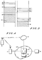
- FIG. 2 shows details of the mobile radio of FIG. 1.
- FIG. 3 shows signals transferred between the mobile radio of FIG. 1 and the two networks of FIG. 1.
- FIG. 4 gives a more specific example of the networks of FIG. 1 for the purposes of explanation of the signals of FIG. 3.
- FIG. 5 is a block diagram of a cordless base station operating as a hub in accordance with a second embodiment of the invention.
- FIG. 6 illustrates two networks and a method of handover therebetween in accordance with the second embodiment of the invention.
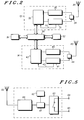
- FIG. 1 The generic problem of handover between two networks is illustrated in FIG. 1.
- network 10 is be a cellular radio network (eg. GSM) and network 11 is be a domestic cordless system or a wireless PABX.
- GSM Global System for Mobile communications
- network 11 is be a domestic cordless system or a wireless PABX.
- Operating on these networks is a mobile subscriber unit in the form of a mobile radio 12 having GSM radio and software elements 13 and cordless radio and software elements 14.
- the GSM radio and software elements 13 include a subscriber identity module with a identification number assigned to the mobile radio user by the operator of network 10 and the cordless radio and software elements 14 include an identification number assigned to the mobile radio user by the operator of network 11. These numbers are selected from the different addressing domains of the different networks 10 and 11.
- the networks 10 and 11 are connected to each other via a third network 15, for example a public switched telephone network (PSTN) or an integrated digital services network (ISDN), which additionally connects networks 10 and 11 to second party equipment, for example a wireline telephone 16.
- PSTN public switched telephone network
- ISDN integrated digital services network
- second party equipment for example a wireline telephone 16.
- equipment 16 being a "telephone”, but it should be understood that equipment 16 could be almost any telecommunications destination, including a mobile radio telephone or a fixed or mobile data terminal.
- Network 15 supports the supplementary service "Call Transfer”, described in CCITT Volume III, Fascicle III.7 "Integrated Services Digital Network General Structure and Service Capabilities", Recommendations I.110-I.257 of November 1988.
- a served user, user X can transform an established call with user Y into (effectively) a call from user Y to a third party, user Z.
- the service provider puts the already established call (with user Y) on hold.
- User X then proceeds to establish the second call (to user Z).
- the service provider would connect users Y and Z together while removing the connections between user X and the other two users.
- user Z will have all the relevant characteristics of the called party, but user Y will not necessarily have all the characteristics of the calling party, depending on whether user Y called user X and also depending on which service or supplementary service is under consideration.
- user X can request completion of the Call Transfer either during or after the establishment of the connection to user Z.
- the service provider will optionally notify users Y and Z of the transfer and, depending on interworking conditions and the supplementary services subscribed to by users Y and Z, will indicate to user Y the number of user Z and will indicate to user Z the number of user Y.
- Normal call transfer is suitable for the purposes of the preferred embodiment of the present invention.
- call transfer is a supplementary service which exists in many communications networks today, for example GSM, DECT and TETRA.
- the GSM radio elements 13 include a transmitter 30, a receiver 31 and baseband processing circuitry 32.
- a receive signal strength indicator (RSSI) 33 passes from the receiver 31 to the circuitry 32.
- a duplexer 34 connects the transmitter and the receiver to an antenna 35.
- the cordless radio elements 14 similarly include a transmitter 40, a receiver 41, baseband processing circuitry 42, an RSSI 43, a duplexer 44 and an antenna 45.
- Controlling both the GSM radio elements 13 and the cordless radio elements 14 is a microprocessor 50 having random access memory 52 and having a releasably connected subscriber identity module (SIM) 51.
- SIM subscriber identity module
- the SIM 51 contains separate identification numbers (IDs) for the GSM cellular radio network and the cordless network. Alternatively, two SIMs can be provided, or one SIM and one hard wired ID or more than one hard wired ID.
- While the mobile radio is shown as having separate receivers and transmitters for the two mobile radio networks, the same hardware elements may be usable for both networks, depending on the frequencies involved, the available switching times for switching between those frequencies and other factors.
- the handover/re-establishment can be triggered by a number of criteria or in a number of circumstances and the specific manner of triggering is not relevant to the present invention.
- the handover can be manually triggered when the user knows he has entered the range of the domestic cordless network 11.
- the operation is as follows. Initially the mobile radio is communicating via network 10 (illustrated by arrow A). The mobile radio enters the range of network 11 and its cordless radio and software elements 14 identify signals from network 11 (arrow B) and complete any necessary registration procedures. The mobile radio decides to trigger a handover, or is instructed to trigger a handover. The mobile radio automatically sends a command to network 10 (arrow C) indicating a "Call Transfer" request to transfer to the user's network 11 address.
- This call transfer request includes the user's network 11 ID (i.e. his PSTN telephone number in the case where network 11 is a cordless telephone network) retrieved from SIM 51.
- network 11 ID i.e. his PSTN telephone number in the case where network 11 is a cordless telephone network
- the ID is sent through GSM layer 3.
- the GSM switch interprets the message and optionally negotiates with the PSTN about performing the transfer.
- the PSTN recognises the GSM number and negotiates with the GSM network about performing the transfer.
- the network 15 commences execution of the call transfer request to the requested address. Since this is an address in network 11, network 15 in effect establishes a communication path from telephone equipment 16 to network 11 (arrow D). Network 11 indicates to the mobile radio 12 that there is an incoming call for the mobile radio. The mobile radio automatically accepts the call from network 11 and the call between the mobile radio and network 10 is dropped.
- An advantage of the arrangement is that no changes to the network are required to enable the handover. All of the new functionality is implemented in the mobile radio 12.
- network 15 is an ISDN network and is referred to as network 220.
- Network 220 has a network switching function 214 with switching control function 216.
- the mobile radio 12 registers with the cellular system (network 10) by means of an exchange of signalling messages 101 and 102 (FIG.3). As an option, additional signalling messages are exchanged at this time, for example to perform mobile authentication, as may be done in GSM.
- a call is initiated on network 10 in step 103, using the protocols of network 10, between second party equipment 16 and mobile radio 12 (FIG.4). During this phase of the call, points a and c are connected in the network switching function 214.
- the mobile radio 12 is able to handover between cells of network 10.
- the mobile acquires and registers with network 11 (steps 104, 105, 106).
- the mobile radio then sends a call transfer request to network 10 which contains the identification number allocated to the mobile radio unit in network 11. This is passed to the switching control function 216 of public network 220.
- the switching control function signals from node b to network 11 that there is an incoming call.
- Network 11 in turn pages the mobile radio (step 109) and the mobile radio responds (step 110).
- the switching function 214 connects nodes a and b and (optionally) suspends the connection between nodes a and c.
- the mobile radio then sends a "Clear Down" message 114 to network 10.
- the switching function under the control of the control function, connects nodes b and c and the call continues (116).
- a farmer with a cordless telephone network in his farmhouse may commence a call in the vicinity of his farmhouse and walk into his field, out of range of the cordless network.
- the farm is covered by a much larger cell of a cellular radio telephone network and the farmer has subscribed to that network, the call can be continued via the cellular network.
- FIG. 5 An example of a central hub in the form of a cordless base station is shown in FIG. 5. It comprises a cordless base station transceiver part 60, logic circuitry 61, storage 62, for storing the user's GSM ID, switch and line control circuit 63 and first and second telephone lines 64 and 65. An antenna 66 is connected to the transceiver part 60.
- network 11 (or a predetermined node of network 11) is the central hub.
- Network 11 is, at least in the preferred embodiment, a domestic cordless telephone base station (illustrated as base station 111) with a two-line connection into the PSTN (network 15). All calls pass to and from the mobile radio 12 through cordless telephone base station 111.
- the mobile radio 12 commences operation (arrow L) within range of the cordless base station 111 and moves out of range of that network but within range of the GSM cellular network 10 (arrow M).
- the mobile radio 12 recognises GSM network 10 and executes a registration procedure on that network (if not already executed) and it informs the cordless base station 111 that a handover to network 10 is requested and it supplies to the cordless network its GSM cellular telephone number (or this is preprogrammed in the cordless base station).
- the cordless base station 111 calls the user's cellular telephone number (arrow N).
- the mobile radio 12 automatically accepts the call from the cellular network.
- the previous cordless link between the mobile radio 12 and base station 111 is disregarded. In a simple network, it is not necessary to "hang up" from the cordless network; the cordless base station merely ignores traffic on its radio interface until a handover back to the cordless network is desired.
- the mobile unit initiates such a call by first dialling the central hub, which then places a second call to the desired number which is supplied by the user. Optionally this process is automated within the mobile radio 12. Since the call has been routed via the cordless base station 111, when the mobile unit comes into range of the cordless base station 111, registration occurs and the base station 111 automatically delivers the call to the mobile radio 12 using the cordless link (arrow L). The cellular telephone call (arrow M) is dropped from the cellular network 10 by the mobile or by the base station 111.
- the call is only be placed via the cordless base station 111 if the identity of the cellular network or a sub-network of cellular network 10 is such that a handover to cordless base station 111 is likely, e.g. because the call is set up in a cellular radio network cell that is known to be the user's "home" cell.
- cordless base station 111 In the case of incoming calls to the mobile radio 12, to enable handover, all calls must be routed via the cordless base station 111.
- the cordless base station 111 upon receiving an incoming call when the mobile radio 12 is not in the range of the cordless base station 111, sets up a connection to the mobile radio via the cellular network 10 using the mobile radio's cellular identity and connects the incoming call to the cellular connection. Handover will then occur in the same way as for mobile initiated calls.
- This arrangement has the advantage that the mobile radio user need provide callers with only a single telephone number for the user to be reached in either network. This number will be the address of the central hub or node of that user in network 11. All routing of calls to the user via the other network 10 is performed by this central hub or node.
- an on-going call through the cellular network need only be routed through the cordless base station 111 when it is determined that a handoff is likely to happen, for example when the mobile radio 12 is known to be in a cellular network or a cell which is known from predetermined information to be close to the cordless base station 111.
- the step of determining that a handover is desired comprises identifying from pretermined cell site information that the mobile subscriber unit and the cordless base station are in a predetermined relationship.
Abstract

Description
- This invention relates to the field of mobile radio and methods of internetwork call handover, for handing over a call from an initial communications network to a target communications network.
- The trend towards increasingly software configurable mobile radio units, together with the growing desire to support continuous uninterrupted service provision between communications systems or networks (eg. UPT, PCS, UMTS) makes the ability to continue a call when crossing network boundaries increasingly important.
- Examples of such boundaries are between a public cellular operator and an indoor office wireless PABX, or between a public cellular network and a domestic cordless network, or between micro-cells and macro-cells supporting the same service provider.
- UK patent application, publication No. 2271040 describes call routing for a portable cellular cordless (PCC) radiotelephone in cordless and cellular telephone systems and describes the handing over of a call in progress from the cellular telephone system to the cordless telephone system by establishing a three-way call through the cellular telephone system. It also describes handing over of a call from the cordless telephone system to the cellular telephone system by performing a three-way call between the PCC radiotelephone operating in the cellular telephone system, a second party and a landline telephone number of a cordless base station for the PCC in the cordless telephone system. Whereas such a three-way call is possible where the cellular telephone system or the public switched telephone network (PSTN) provides for such a facility, this is not always the case. In addition, the performance of such an arrangement may not be optimal in the case (as here) where two "parties" of the three-way call are the same, unless there is provision to avoid path-delay mismatching, giving rise to echoes.
- US patent No. 5,127,042 describes a cellular cordless telephone operating with both a cordless base station and a cellular base station and describes the use of a "call waiting" facility at the called party to perform automatic transfer of a call between a cellular telephone call and a cordless telephone call. Such an arrangement is possible where the called party is known to have a call waiting capability, but this is not always the case.
- There is a need for an improved metod of inter-network call handover.
- According to a first aspect of the present invention 1a method is provided of inter-network call handover, for handing over a call from an initial communications network to a target communications network, comprising the steps of establishing a call between a mobile subscriber unit and the initial communications network using a first identification number allocated to that unit in the initial network, identifying that a handover to the target network is desired providing the initial network with a second identification number allocated to the unit in the target network; initiating a call transfer request to establish a call to the unit in the target network using the second identification number and establishing a new link in the target network using the second identification number.
- Thus the invention provides simultaneous operation by a mobile unit on two networks and the automatic invocation of existing or new network services to transfer the call, which gives rise to the benefit of call continuation with little disruption, which is a feature not available today.
- The boundaries of a network are defined by its addressing domain. A unit or node that is able correctly to understand the addressing domain of a network is part of that network. The invention enables call handovers across these boundaries.
- The request to establish a call to the unit in the target network is, in this aspect, a call transfer request, that is to say a request to implement an operation by which an established (i.e. active) call is transferred to a third party, where the user served by the call transfer operation is either a called or a calling party. In this embodiment, the "third party" may appear to the initial network as a third party, while in fact the third party is the same mobile subscriber unit identified by a new identification number allocated to that unit in the target network. Call transfer is a known supplementary service defined by CCITT.
- According to a second aspect of the present invention, a method of inter-network call handover is provided, for handing over a call from an initial communications network to a target communications network, comprising the steps of: establishing a call between a mobile subscriber unit and the initial communications network using a first identification number allocated to that unit in the initial network; pre-providing, to a predetermined node in the initial network, a second identification number allocated to the unit in the target network; identifying that a handover to the target network is desired; initiating a request to establish a call to the unit in the target network using the second identification number by providing a signal from the mobile subscriber unit to the predetermined node requesting a handover to the mobile subscriber unit identified by the second identification number; and establishing a new link in the target network using the second identification number.In an alternative embodiment, the second identification number is pre-provided to a predetermined node in the initial network, for example a "home" base station or a cordless (i.e. short-range, dedicated or private-shared) base station, and the step of initiating a request comprises providing a signal from the mobile subscriber unit to the predetermined node requesting a handover to the mobile subscriber unit identified by the second identification number. This embodiment is particularly useful where a call is initially set up to or from the home base station or cordless base station and the subscriber moves away from that location while the call is in progress.
- A benefit of this aspect of the invention is that the predetermined node can be established in a network which has lower call tariffs and the arrangement provides a mechanism for handing over from that network or to that network under the user's control, thereby enabling the user to take full advantage of the lower call tariffs.
- The predetermined node preferably has two communications channels (e.g. telephone lines) in addition to its communication channel to the mobile subscriber unit. While the call is ongoing on one of these channels, the predetermined node can use the other channel to set up a path of communication to the target network, which in turn establishes radio communication with the mobile subscriber unit.
- In a further aspect of the invention, a method of inter-network call handover is provided, for handing over a call between a mobile subscriber unit and a second party from an initial communications network to a target communications network, comprising the steps of: associating the mobile subscriber unit with a first identification number allocated to the mobile subscriber unit in the target network and with a predetermined node in the target network; establishing a call between a mobile subscriber unit and the initial communications network using a second identification number allocated to that unit in the initial network; establishing a communication path between the mobile subscriber unit and the predetermined node in the target network via the initial network; establishing a communication path between the predetermined node in the target network and the second party; and linking, at the predetermined node, the two communication paths; identifying that a handover to the target network is desired; establishing a call to the mobile subscriber unit in the target network using the second identification number; and connecting, at the predetermined node, the mobile subscriber unit and the second party.
- As a further step, the communication path between the mobile subscriber unit and the initial network is preferably released, as is the communication path between the predetermined node and the initial network.
- This aspect of the invention is particularly applicable where the predetermined node is located in the target network, for example in the case where the predetermined node is a cordless base station, it is applicable to roaming inwards towards that base station.
- Preferred embodiments of the invention will now be described, by way of example only, with reference to the drawings.
- FIG. 1 illustrates two networks and a method of handover therebetween in accordance with a first embodiment of the invention.
- FIG. 2 shows details of the mobile radio of FIG. 1.
- FIG. 3 shows signals transferred between the mobile radio of FIG. 1 and the two networks of FIG. 1.
- FIG. 4 gives a more specific example of the networks of FIG. 1 for the purposes of explanation of the signals of FIG. 3.
- FIG. 5 is a block diagram of a cordless base station operating as a hub in accordance with a second embodiment of the invention.
- FIG. 6 illustrates two networks and a method of handover therebetween in accordance with the second embodiment of the invention.
- The generic problem of handover between two networks is illustrated in FIG. 1.
- In FIG. 1, two mobile radio networks are shown, 10 and 11. As an example,
network 10 is be a cellular radio network (eg. GSM) andnetwork 11 is be a domestic cordless system or a wireless PABX. Operating on these networks is a mobile subscriber unit in the form of amobile radio 12 having GSM radio andsoftware elements 13 and cordless radio andsoftware elements 14. - The GSM radio and
software elements 13 include a subscriber identity module with a identification number assigned to the mobile radio user by the operator ofnetwork 10 and the cordless radio andsoftware elements 14 include an identification number assigned to the mobile radio user by the operator ofnetwork 11. These numbers are selected from the different addressing domains of thedifferent networks - The
networks third network 15, for example a public switched telephone network (PSTN) or an integrated digital services network (ISDN), which additionally connectsnetworks wireline telephone 16. Reference will be made in this description to theequipment 16 being a "telephone", but it should be understood thatequipment 16 could be almost any telecommunications destination, including a mobile radio telephone or a fixed or mobile data terminal. -
Network 15 supports the supplementary service "Call Transfer", described in CCITT Volume III, Fascicle III.7 "Integrated Services Digital Network General Structure and Service Capabilities", Recommendations I.110-I.257 of November 1988. - From that document, the general principle of call transfer is as follows. The Call Transfer supplementary service is subscribed to by prior arrangements with the service provider. Subscription can be made for "Normal Call Transfer" and/or for either of the alternate procedures (ie. "Single-Step Call Transfer" or "Explicit Call Transfer") offered by the service provider.
- A served user, user X, can transform an established call with user Y into (effectively) a call from user Y to a third party, user Z. When the served user (user X) asks the service provider to begin the "Normal" Call Transfer, the service provider puts the already established call (with user Y) on hold. User X then proceeds to establish the second call (to user Z). Upon request from user X to complete the Call Transfer, the service provider would connect users Y and Z together while removing the connections between user X and the other two users.
- In the resulting call Y to Z, user Z will have all the relevant characteristics of the called party, but user Y will not necessarily have all the characteristics of the calling party, depending on whether user Y called user X and also depending on which service or supplementary service is under consideration.
- In some networks, user X can request completion of the Call Transfer either during or after the establishment of the connection to user Z.
- The service provider will optionally notify users Y and Z of the transfer and, depending on interworking conditions and the supplementary services subscribed to by users Y and Z, will indicate to user Y the number of user Z and will indicate to user Z the number of user Y.
- Normal call transfer is suitable for the purposes of the preferred embodiment of the present invention.
- It is not necessary that the call transfer service is implemented in
network 15. It can instead be implemented innetwork 10. Call transfer is a supplementary service which exists in many communications networks today, for example GSM, DECT and TETRA. - Details of the
mobile radio 12 are shown in FIG. 2. TheGSM radio elements 13 include atransmitter 30, areceiver 31 andbaseband processing circuitry 32. A receive signal strength indicator (RSSI) 33 passes from thereceiver 31 to thecircuitry 32. Aduplexer 34 connects the transmitter and the receiver to anantenna 35. thecordless radio elements 14 similarly include atransmitter 40, areceiver 41,baseband processing circuitry 42, anRSSI 43, aduplexer 44 and anantenna 45. - Controlling both the
GSM radio elements 13 and thecordless radio elements 14 is amicroprocessor 50 havingrandom access memory 52 and having a releasably connected subscriber identity module (SIM) 51. - The
SIM 51 contains separate identification numbers (IDs) for the GSM cellular radio network and the cordless network. Alternatively, two SIMs can be provided, or one SIM and one hard wired ID or more than one hard wired ID. - While the mobile radio is shown as having separate receivers and transmitters for the two mobile radio networks, the same hardware elements may be usable for both networks, depending on the frequencies involved, the available switching times for switching between those frequencies and other factors.
- Referring to FIGs. 1 and 2 together, the case will now be considered where, for reasons of deteriorating signal quality as indicated by RSSI 33 (or some other quality measure), or merely reasons of differential call charges, the user of the
mobile radio 12 , while in communication with thesecond party equipment 16 vianetworks network 11 using the mobile radio's multimode capability. Such a handover/re-establishment can be triggered by a number of criteria or in a number of circumstances and the specific manner of triggering is not relevant to the present invention. For example, the handover can be manually triggered when the user knows he has entered the range of the domesticcordless network 11. - The operation is as follows. Initially the mobile radio is communicating via network 10 (illustrated by arrow A). The mobile radio enters the range of
network 11 and its cordless radio andsoftware elements 14 identify signals from network 11 (arrow B) and complete any necessary registration procedures. The mobile radio decides to trigger a handover, or is instructed to trigger a handover. The mobile radio automatically sends a command to network 10 (arrow C) indicating a "Call Transfer" request to transfer to the user'snetwork 11 address. - This call transfer request includes the user's
network 11 ID (i.e. his PSTN telephone number in the case wherenetwork 11 is a cordless telephone network) retrieved fromSIM 51. - In the case of a GSM-to-cordless transfer, the ID is sent through GSM layer 3. The GSM switch interprets the message and optionally negotiates with the PSTN about performing the transfer.
- In the case of a cordless-to-GSM transfer, the PSTN recognises the GSM number and negotiates with the GSM network about performing the transfer.
- The
network 15 commences execution of the call transfer request to the requested address. Since this is an address innetwork 11,network 15 in effect establishes a communication path fromtelephone equipment 16 to network 11 (arrow D).Network 11 indicates to themobile radio 12 that there is an incoming call for the mobile radio. The mobile radio automatically accepts the call fromnetwork 11 and the call between the mobile radio andnetwork 10 is dropped. - An advantage of the arrangement is that no changes to the network are required to enable the handover. All of the new functionality is implemented in the
mobile radio 12. - The above procedure is described in more detail with reference to FIGs. 3 and 4. In the example of FIG. 4,
network 15 is an ISDN network and is referred to asnetwork 220.Network 220 has anetwork switching function 214 with switchingcontrol function 216. - The
mobile radio 12 registers with the cellular system (network 10) by means of an exchange of signallingmessages 101 and 102 (FIG.3). As an option, additional signalling messages are exchanged at this time, for example to perform mobile authentication, as may be done in GSM. A call is initiated onnetwork 10 instep 103, using the protocols ofnetwork 10, betweensecond party equipment 16 and mobile radio 12 (FIG.4). During this phase of the call, points a and c are connected in thenetwork switching function 214. - The
mobile radio 12 is able to handover between cells ofnetwork 10. At some point during the call, the mobile acquires and registers with network 11 (steps 104, 105, 106). The mobile radio then sends a call transfer request to network 10 which contains the identification number allocated to the mobile radio unit innetwork 11. This is passed to the switchingcontrol function 216 ofpublic network 220. The switching control function signals from node b to network 11 that there is an incoming call.Network 11 in turn pages the mobile radio (step 109) and the mobile radio responds (step 110). At this point, theswitching function 214 connects nodes a and b and (optionally) suspends the connection between nodes a and c. The mobile radio then sends a "Clear Down"message 114 tonetwork 10. At this point the switching function, under the control of the control function, connects nodes b and c and the call continues (116). - Many situations can be considered where the method described is useful. For example a farmer with a cordless telephone network in his farmhouse may commence a call in the vicinity of his farmhouse and walk into his field, out of range of the cordless network. Provided that the farm is covered by a much larger cell of a cellular radio telephone network and the farmer has subscribed to that network, the call can be continued via the cellular network.
- A second method of achieving inter-network call handover is now described, in which all calls are routed through a central hub or predetermined node.
- In this method, all calls to and from a mobile radio always pass through a common point or 'central hub' regardless of which network the mobile radio is using. This central hub must be capable of setting up a simultaneous call to an address on another network.
- An example of a central hub in the form of a cordless base station is shown in FIG. 5. it comprises a cordless base
station transceiver part 60,logic circuitry 61,storage 62, for storing the user's GSM ID, switch andline control circuit 63 and first andsecond telephone lines antenna 66 is connected to thetransceiver part 60. - An example of operation will be described with reference to FIG.6. In this example, network 11 (or a predetermined node of network 11) is the central hub.
Network 11 is, at least in the preferred embodiment, a domestic cordless telephone base station (illustrated as base station 111) with a two-line connection into the PSTN (network 15). All calls pass to and from themobile radio 12 through cordlesstelephone base station 111. - Considering first the case where the
mobile radio 12 commences operation (arrow L) within range of thecordless base station 111 and moves out of range of that network but within range of the GSM cellular network 10 (arrow M). When the need for a handover is identified, themobile radio 12 recognisesGSM network 10 and executes a registration procedure on that network (if not already executed) and it informs thecordless base station 111 that a handover to network 10 is requested and it supplies to the cordless network its GSM cellular telephone number (or this is preprogrammed in the cordless base station). Thecordless base station 111 calls the user's cellular telephone number (arrow N). Themobile radio 12 automatically accepts the call from the cellular network. The previous cordless link between themobile radio 12 andbase station 111 is disregarded. In a simple network, it is not necessary to "hang up" from the cordless network; the cordless base station merely ignores traffic on its radio interface until a handover back to the cordless network is desired. - For the process of handing over from
network 10 to network 11, the following procedures take place. - Considering first the case of a mobile initiated call. The mobile unit initiates such a call by first dialling the central hub, which then places a second call to the desired number which is supplied by the user. Optionally this process is automated within the
mobile radio 12. Since the call has been routed via thecordless base station 111, when the mobile unit comes into range of thecordless base station 111, registration occurs and thebase station 111 automatically delivers the call to themobile radio 12 using the cordless link (arrow L). The cellular telephone call (arrow M) is dropped from thecellular network 10 by the mobile or by thebase station 111. - As a refinement to the method, to avoid inefficient call routing, the call is only be placed via the
cordless base station 111 if the identity of the cellular network or a sub-network ofcellular network 10 is such that a handover tocordless base station 111 is likely, e.g. because the call is set up in a cellular radio network cell that is known to be the user's "home" cell. - In the case of incoming calls to the
mobile radio 12, to enable handover, all calls must be routed via thecordless base station 111. Thecordless base station 111, upon receiving an incoming call when themobile radio 12 is not in the range of thecordless base station 111, sets up a connection to the mobile radio via thecellular network 10 using the mobile radio's cellular identity and connects the incoming call to the cellular connection. Handover will then occur in the same way as for mobile initiated calls. - This arrangement has the advantage that the mobile radio user need provide callers with only a single telephone number for the user to be reached in either network. This number will be the address of the central hub or node of that user in
network 11. All routing of calls to the user via theother network 10 is performed by this central hub or node. - As a particularly preferred, but not necessarily essential feature, an on-going call through the cellular network need only be routed through the
cordless base station 111 when it is determined that a handoff is likely to happen, for example when themobile radio 12 is known to be in a cellular network or a cell which is known from predetermined information to be close to thecordless base station 111. Thus the step of determining that a handover is desired comprises identifying from pretermined cell site information that the mobile subscriber unit and the cordless base station are in a predetermined relationship.
Claims (8)
- A method of inter-network call handover, for handing over a call from an initial communications network to a target communications network, comprising the steps of:
establishing a call between a mobile subscriber unit and the initial communications network using a first identification number allocated to that unit in the initial network,
identifying that a handover to the target network is desired
providing the initial network with a second identification number allocated to the unit in the target network;
initiating a call transfer request to establish a call to the unit in the target network using the second identification number and
establishing a new link in the target network using the second identification number. - A method of inter-network call handover, for handing over a call from an initial communications network to a target communications network, comprising the steps of:
establishing a call between a mobile subscriber unit and the initial communications network using a first identification number allocated to that unit in the initial network;
pre-providing, to a predetermined node in the initial network, a second identification number allocated to the unit in the target network;
identifying that a handover to the target network is desired;
initiating a request to establish a call to the unit in the target network using the second identification number by providing a signal from the mobile subscriber unit to the predetermined node requesting a handover to the mobile subscriber unit identified by the second identification number; and
establishing a new link in the target network using the second identification number. - A method according to claim 2, comprising the initial step of establishing a communication path between the predetermined node and a second party, wherein the predetermined node establishes a communication path to the mobile subscriber unit via the target network, maintains the communication path to the second party and links the two communication paths.
- A method according to either of claims 2 and 3, wherein the predetermined node is a cordless base station.
- A method of inter-network call handover, for handing over a call between a mobile subscriber unit and a second party from an initial communications network to a target communications network, comprising the steps of:
associating the mobile subscriber unit with a first identification number allocated to the mobile subscriber unit in the target network and with a predetermined node in the target network;
establishing a call between the mobile subscriber unit and the initial communications network using a second identification number allocated to that unit in the initial network;
establishing a communication path between the mobile subscriber unit and the predetermined node in the target network via the initial network;
establishing a communication path between the predetermined node in the target network and the second party and linking, at the predetermined node, the two communication paths;
identifying that a handover to the target network is desired;
establishing a call to the mobile subscriber unit in the target network using the second identification number; and
connecting, at the predetermined node, the mobile subscriber unit and the second party. - A method according to claim 5, comprising the further step of disconnecting the call between the mobile subscriber unit and the initial communications network.
- A method according to claim 5, wherein the predetermined node is a cordless base station.
- A method according to claim 7, wherein the step of determining that a handover is desired comprises identifying from pretermined cell site information that the mobile subscriber unit and the cordless base station are in a predetermined relationship.
Applications Claiming Priority (2)
| Application Number | Priority Date | Filing Date | Title |
|---|---|---|---|
| GB9406697A GB2288301B (en) | 1994-04-05 | 1994-04-05 | Methods and apparatus for call handover between different mobile radio networks |
| GB9406697 | 1994-04-05 |
Publications (3)
| Publication Number | Publication Date |
|---|---|
| EP0676907A2 true EP0676907A2 (en) | 1995-10-11 |
| EP0676907A3 EP0676907A3 (en) | 1995-12-20 |
| EP0676907B1 EP0676907B1 (en) | 2004-06-23 |
Family
ID=10753026
Family Applications (1)
| Application Number | Title | Priority Date | Filing Date |
|---|---|---|---|
| EP95103831A Expired - Lifetime EP0676907B1 (en) | 1994-04-05 | 1995-03-16 | Method and apparatus for call handover between different mobile radio networks |
Country Status (4)
| Country | Link |
|---|---|
| EP (1) | EP0676907B1 (en) |
| AT (1) | ATE270025T1 (en) |
| DE (1) | DE69533182T2 (en) |
| GB (1) | GB2321165A (en) |
Cited By (3)
| Publication number | Priority date | Publication date | Assignee | Title |
|---|---|---|---|---|
| WO1999063762A2 (en) * | 1998-06-03 | 1999-12-09 | Nokia Networks Oy | Method for identifying a call in a telecommunications system |
| EP1058471A2 (en) * | 1999-05-28 | 2000-12-06 | Nec Corporation | Mobile telecommunications system |
| EP1527639A1 (en) * | 2002-06-26 | 2005-05-04 | Motorola, Inc. | Method and apparatus for implementing bi-directional soft handovers between wireless networks without carrier control |
Families Citing this family (4)
| Publication number | Priority date | Publication date | Assignee | Title |
|---|---|---|---|---|
| US7414992B2 (en) | 2003-06-30 | 2008-08-19 | Motorola, Inc. | Method and apparatus for providing a hand-in to a wireless local area network |
| CN101207925B (en) * | 2007-12-13 | 2010-12-08 | 上海华为技术有限公司 | Switch method, exchange equipment and terminal equipment |
| US10506666B2 (en) | 2018-05-01 | 2019-12-10 | Intermetro Communications, Inc. | Multiple active network wireless device |
| US11812515B2 (en) | 2018-05-01 | 2023-11-07 | Intermetro Communications, Inc. | Multiple active network wireless device using a shadow number |
Citations (6)
| Publication number | Priority date | Publication date | Assignee | Title |
|---|---|---|---|---|
| WO1989007380A1 (en) * | 1988-01-27 | 1989-08-10 | Motorola, Inc. | Trunked communication system with nationwide roaming capability |
| EP0379642A2 (en) * | 1988-09-19 | 1990-08-01 | Gte Telecommunication Services Incorporated | System for the extended provision of cellular mobile radiotelephone service |
| EP0512962A2 (en) * | 1991-02-05 | 1992-11-11 | Telefonaktiebolaget L M Ericsson | Cellular communications network including subscriber interrogation points |
| WO1993007721A1 (en) * | 1991-10-03 | 1993-04-15 | Nokia Telecommunications Oy | A telecommunication system and a method for matching the numbering schemes of two telecommunication systems |
| EP0570643A1 (en) * | 1992-05-18 | 1993-11-24 | AT&T Corp. | Handover of mobile radio calls between mobile switching centers |
| GB2280085A (en) * | 1993-06-25 | 1995-01-18 | Vodafone Ltd | Cellular telephone systems |
Family Cites Families (1)
| Publication number | Priority date | Publication date | Assignee | Title |
|---|---|---|---|---|
| BR9304158A (en) * | 1992-02-06 | 1994-08-02 | Motorola Inc | Communications system, mobile portable unit, and process of operating communications system |
-
1994
- 1994-04-05 GB GB9807283A patent/GB2321165A/en not_active Withdrawn
-
1995
- 1995-03-16 AT AT95103831T patent/ATE270025T1/en not_active IP Right Cessation
- 1995-03-16 DE DE69533182T patent/DE69533182T2/en not_active Expired - Lifetime
- 1995-03-16 EP EP95103831A patent/EP0676907B1/en not_active Expired - Lifetime
Patent Citations (6)
| Publication number | Priority date | Publication date | Assignee | Title |
|---|---|---|---|---|
| WO1989007380A1 (en) * | 1988-01-27 | 1989-08-10 | Motorola, Inc. | Trunked communication system with nationwide roaming capability |
| EP0379642A2 (en) * | 1988-09-19 | 1990-08-01 | Gte Telecommunication Services Incorporated | System for the extended provision of cellular mobile radiotelephone service |
| EP0512962A2 (en) * | 1991-02-05 | 1992-11-11 | Telefonaktiebolaget L M Ericsson | Cellular communications network including subscriber interrogation points |
| WO1993007721A1 (en) * | 1991-10-03 | 1993-04-15 | Nokia Telecommunications Oy | A telecommunication system and a method for matching the numbering schemes of two telecommunication systems |
| EP0570643A1 (en) * | 1992-05-18 | 1993-11-24 | AT&T Corp. | Handover of mobile radio calls between mobile switching centers |
| GB2280085A (en) * | 1993-06-25 | 1995-01-18 | Vodafone Ltd | Cellular telephone systems |
Cited By (15)
| Publication number | Priority date | Publication date | Assignee | Title |
|---|---|---|---|---|
| AU756365B2 (en) * | 1998-06-03 | 2003-01-09 | Nokia Corporation | Method for identifying a call in a telecommunications system |
| WO1999063762A3 (en) * | 1998-06-03 | 2000-02-17 | Nokia Networks Oy | Method for identifying a call in a telecommunications system |
| US6560458B1 (en) | 1998-06-03 | 2003-05-06 | Nokia Corporation | Method for identifying a call in a telecommunications system |
| WO1999063762A2 (en) * | 1998-06-03 | 1999-12-09 | Nokia Networks Oy | Method for identifying a call in a telecommunications system |
| EP1058471A3 (en) * | 1999-05-28 | 2001-02-28 | Nec Corporation | Mobile telecommunications system |
| EP1235455A1 (en) * | 1999-05-28 | 2002-08-28 | Nec Corporation | Mobile telecommunications system with handover between a GSM network and a UMTS network |
| EP1058471A2 (en) * | 1999-05-28 | 2000-12-06 | Nec Corporation | Mobile telecommunications system |
| US6725039B1 (en) | 1999-05-28 | 2004-04-20 | Nec Corporation | Mobile telecommunications system |
| US8107962B2 (en) | 1999-05-28 | 2012-01-31 | Nec Corporation | Mobile telecommunications system |
| US8792893B2 (en) | 1999-05-28 | 2014-07-29 | Nec Corporation | Mobile telecommunications system |
| US9247582B2 (en) | 1999-05-28 | 2016-01-26 | Nec Corporation | Mobile telecommunications system |
| US9591538B2 (en) | 1999-05-28 | 2017-03-07 | Nec Corporation | Mobile telecommunications system |
| US10028189B2 (en) | 1999-05-28 | 2018-07-17 | Nec Corporation | Mobile telecommunications system |
| EP1527639A1 (en) * | 2002-06-26 | 2005-05-04 | Motorola, Inc. | Method and apparatus for implementing bi-directional soft handovers between wireless networks without carrier control |
| EP1527639A4 (en) * | 2002-06-26 | 2010-08-25 | Motorola Inc | Method and apparatus for implementing bi-directional soft handovers between wireless networks without carrier control |
Also Published As
| Publication number | Publication date |
|---|---|
| EP0676907B1 (en) | 2004-06-23 |
| DE69533182T2 (en) | 2004-10-21 |
| GB9807283D0 (en) | 1998-06-03 |
| DE69533182D1 (en) | 2004-07-29 |
| ATE270025T1 (en) | 2004-07-15 |
| GB2321165A (en) | 1998-07-15 |
| EP0676907A3 (en) | 1995-12-20 |
Similar Documents
| Publication | Publication Date | Title |
|---|---|---|
| CA2354078C (en) | Establishing calls and processing on-going calls in fixed and cellular networks | |
| GB2288301A (en) | Methods and apparatus for call handover between different mobile radio networks | |
| US5930712A (en) | Dual mode subscriber terminal, single mode subscriber terminal and a handover procedure of the dual mode subscriber terminal and the single mode subscriber terminal in a mobile telecommunications network | |
| US5913166A (en) | Arrangement for providing a call hand-off for a mobile station from a land-line supported private base station to a cellular base station operating in a cellular system | |
| US5659598A (en) | Dual mode subscriber terminal and a handover procedure of the dual mode subscriber terminal in a mobile telecommunication network | |
| US5440613A (en) | Architecture for a cellular wireless telecommunication system | |
| EP0695104B1 (en) | Mobile telephone connection transfer | |
| US5771465A (en) | Apparatus for providing a mobility adjunct for the public switched telephone network | |
| US7313412B2 (en) | Service management | |
| TW550962B (en) | Paging in a mobile telecommunication network | |
| EP0725552A2 (en) | Method and arrangement for transfer between a cordless telecommunaction system and a cellular mobile telecommunication system | |
| US7103360B2 (en) | Switching telephone calls between wireline and cellular telephones | |
| US7289808B1 (en) | Inter-system handover | |
| CA2097351C (en) | Architecture for a wireless telecommunication system | |
| JP2003319454A (en) | Method and system for controlling call connection | |
| EP0676907B1 (en) | Method and apparatus for call handover between different mobile radio networks | |
| JPH10248088A (en) | Communication system | |
| CA2353898C (en) | Cellular-fixed call completion and call transfer service from a cellular network provider | |
| JP4705208B2 (en) | System and method for handling dropped calls | |
| JP3039586B2 (en) | Mobile communication system |
Legal Events
| Date | Code | Title | Description |
|---|---|---|---|
| PUAI | Public reference made under article 153(3) epc to a published international application that has entered the european phase |
Free format text: ORIGINAL CODE: 0009012 |
|
| AK | Designated contracting states |
Kind code of ref document: A2 Designated state(s): AT BE CH DE DK ES FR GB GR IE IT LI NL SE |
|
| PUAL | Search report despatched |
Free format text: ORIGINAL CODE: 0009013 |
|
| AK | Designated contracting states |
Kind code of ref document: A3 Designated state(s): AT BE CH DE DK ES FR GB GR IE IT LI NL SE |
|
| 17P | Request for examination filed |
Effective date: 19960620 |
|
| 17Q | First examination report despatched |
Effective date: 20020320 |
|
| GRAP | Despatch of communication of intention to grant a patent |
Free format text: ORIGINAL CODE: EPIDOSNIGR1 |
|
| GRAS | Grant fee paid |
Free format text: ORIGINAL CODE: EPIDOSNIGR3 |
|
| GRAA | (expected) grant |
Free format text: ORIGINAL CODE: 0009210 |
|
| RBV | Designated contracting states (corrected) |
Designated state(s): AT BE CH DE DK ES FR GR IE IT LI NL SE |
|
| AK | Designated contracting states |
Kind code of ref document: B1 Designated state(s): AT BE CH DE DK ES FR GR IE IT LI NL SE |
|
| PG25 | Lapsed in a contracting state [announced via postgrant information from national office to epo] |
Ref country code: NL Free format text: LAPSE BECAUSE OF FAILURE TO SUBMIT A TRANSLATION OF THE DESCRIPTION OR TO PAY THE FEE WITHIN THE PRESCRIBED TIME-LIMIT Effective date: 20040623 Ref country code: LI Free format text: LAPSE BECAUSE OF FAILURE TO SUBMIT A TRANSLATION OF THE DESCRIPTION OR TO PAY THE FEE WITHIN THE PRESCRIBED TIME-LIMIT Effective date: 20040623 Ref country code: IT Free format text: LAPSE BECAUSE OF FAILURE TO SUBMIT A TRANSLATION OF THE DESCRIPTION OR TO PAY THE FEE WITHIN THE PRE;WARNING: LAPSES OF ITALIAN PATENTS WITH EFFECTIVE DATE BEFORE 2007 MAY HAVE OCCURRED AT ANY TIME BEFORE 2007. THE CORRECT EFFECTIVE DATE MAY BE DIFFERENT FROM THE ONE RECORDED.SCRIBED TIME-LIMIT Effective date: 20040623 Ref country code: CH Free format text: LAPSE BECAUSE OF FAILURE TO SUBMIT A TRANSLATION OF THE DESCRIPTION OR TO PAY THE FEE WITHIN THE PRESCRIBED TIME-LIMIT Effective date: 20040623 Ref country code: BE Free format text: LAPSE BECAUSE OF FAILURE TO SUBMIT A TRANSLATION OF THE DESCRIPTION OR TO PAY THE FEE WITHIN THE PRESCRIBED TIME-LIMIT Effective date: 20040623 Ref country code: AT Free format text: LAPSE BECAUSE OF FAILURE TO SUBMIT A TRANSLATION OF THE DESCRIPTION OR TO PAY THE FEE WITHIN THE PRESCRIBED TIME-LIMIT Effective date: 20040623 |
|
| REG | Reference to a national code |
Ref country code: CH Ref legal event code: EP |
|
| REG | Reference to a national code |
Ref country code: IE Ref legal event code: FG4D |
|
| REF | Corresponds to: |
Ref document number: 69533182 Country of ref document: DE Date of ref document: 20040729 Kind code of ref document: P |
|
| PG25 | Lapsed in a contracting state [announced via postgrant information from national office to epo] |
Ref country code: SE Free format text: LAPSE BECAUSE OF FAILURE TO SUBMIT A TRANSLATION OF THE DESCRIPTION OR TO PAY THE FEE WITHIN THE PRESCRIBED TIME-LIMIT Effective date: 20040923 Ref country code: GR Free format text: LAPSE BECAUSE OF FAILURE TO SUBMIT A TRANSLATION OF THE DESCRIPTION OR TO PAY THE FEE WITHIN THE PRESCRIBED TIME-LIMIT Effective date: 20040923 Ref country code: DK Free format text: LAPSE BECAUSE OF FAILURE TO SUBMIT A TRANSLATION OF THE DESCRIPTION OR TO PAY THE FEE WITHIN THE PRESCRIBED TIME-LIMIT Effective date: 20040923 |
|
| PG25 | Lapsed in a contracting state [announced via postgrant information from national office to epo] |
Ref country code: ES Free format text: LAPSE BECAUSE OF FAILURE TO SUBMIT A TRANSLATION OF THE DESCRIPTION OR TO PAY THE FEE WITHIN THE PRESCRIBED TIME-LIMIT Effective date: 20041004 |
|
| NLV1 | Nl: lapsed or annulled due to failure to fulfill the requirements of art. 29p and 29m of the patents act | ||
| REG | Reference to a national code |
Ref country code: CH Ref legal event code: PL |
|
| PG25 | Lapsed in a contracting state [announced via postgrant information from national office to epo] |
Ref country code: IE Free format text: LAPSE BECAUSE OF NON-PAYMENT OF DUE FEES Effective date: 20050316 |
|
| ET | Fr: translation filed | ||
| PLBE | No opposition filed within time limit |
Free format text: ORIGINAL CODE: 0009261 |
|
| STAA | Information on the status of an ep patent application or granted ep patent |
Free format text: STATUS: NO OPPOSITION FILED WITHIN TIME LIMIT |
|
| 26N | No opposition filed |
Effective date: 20050324 |
|
| REG | Reference to a national code |
Ref country code: IE Ref legal event code: MM4A |
|
| REG | Reference to a national code |
Ref country code: DE Ref legal event code: R081 Ref document number: 69533182 Country of ref document: DE Owner name: MOTOROLA MOBILITY, INC. ( N.D. GES. D. STAATES, US Free format text: FORMER OWNER: MOTOROLA, INC., SCHAUMBURG, ILL., US Effective date: 20110324 Ref country code: DE Ref legal event code: R081 Ref document number: 69533182 Country of ref document: DE Owner name: MOTOROLA MOBILITY, INC. ( N.D. GES. D. STAATES, US Free format text: FORMER OWNER: MOTOROLA, INC., SCHAUMBURG, US Effective date: 20110324 |
|
| REG | Reference to a national code |
Ref country code: FR Ref legal event code: TP Owner name: MOTOROLA MOBILITY, INC., US Effective date: 20110912 |
|
| PGFP | Annual fee paid to national office [announced via postgrant information from national office to epo] |
Ref country code: DE Payment date: 20140331 Year of fee payment: 20 |
|
| PGFP | Annual fee paid to national office [announced via postgrant information from national office to epo] |
Ref country code: FR Payment date: 20140225 Year of fee payment: 20 |
|
| REG | Reference to a national code |
Ref country code: DE Ref legal event code: R071 Ref document number: 69533182 Country of ref document: DE |
|
| P01 | Opt-out of the competence of the unified patent court (upc) registered |
Effective date: 20230520 |