EP0676830A2 - Electrical connector housing assembly with improved locking means - Google Patents
Electrical connector housing assembly with improved locking means Download PDFInfo
- Publication number
- EP0676830A2 EP0676830A2 EP95105028A EP95105028A EP0676830A2 EP 0676830 A2 EP0676830 A2 EP 0676830A2 EP 95105028 A EP95105028 A EP 95105028A EP 95105028 A EP95105028 A EP 95105028A EP 0676830 A2 EP0676830 A2 EP 0676830A2
- Authority
- EP
- European Patent Office
- Prior art keywords
- connector assembly
- mating
- arm
- gear member
- retention arm
- Prior art date
- Legal status (The legal status is an assumption and is not a legal conclusion. Google has not performed a legal analysis and makes no representation as to the accuracy of the status listed.)
- Granted
Links
Images


Classifications
-
- H—ELECTRICITY
- H01—ELECTRIC ELEMENTS
- H01R—ELECTRICALLY-CONDUCTIVE CONNECTIONS; STRUCTURAL ASSOCIATIONS OF A PLURALITY OF MUTUALLY-INSULATED ELECTRICAL CONNECTING ELEMENTS; COUPLING DEVICES; CURRENT COLLECTORS
- H01R13/00—Details of coupling devices of the kinds covered by groups H01R12/70 or H01R24/00 - H01R33/00
- H01R13/62—Means for facilitating engagement or disengagement of coupling parts or for holding them in engagement
- H01R13/629—Additional means for facilitating engagement or disengagement of coupling parts, e.g. aligning or guiding means, levers, gas pressure electrical locking indicators, manufacturing tolerances
- H01R13/62933—Comprising exclusively pivoting lever
- H01R13/62944—Pivoting lever comprising gear teeth
-
- H—ELECTRICITY
- H01—ELECTRIC ELEMENTS
- H01R—ELECTRICALLY-CONDUCTIVE CONNECTIONS; STRUCTURAL ASSOCIATIONS OF A PLURALITY OF MUTUALLY-INSULATED ELECTRICAL CONNECTING ELEMENTS; COUPLING DEVICES; CURRENT COLLECTORS
- H01R12/00—Structural associations of a plurality of mutually-insulated electrical connecting elements, specially adapted for printed circuits, e.g. printed circuit boards [PCB], flat or ribbon cables, or like generally planar structures, e.g. terminal strips, terminal blocks; Coupling devices specially adapted for printed circuits, flat or ribbon cables, or like generally planar structures; Terminals specially adapted for contact with, or insertion into, printed circuits, flat or ribbon cables, or like generally planar structures
- H01R12/70—Coupling devices
- H01R12/71—Coupling devices for rigid printing circuits or like structures
- H01R12/72—Coupling devices for rigid printing circuits or like structures coupling with the edge of the rigid printed circuits or like structures
- H01R12/722—Coupling devices for rigid printing circuits or like structures coupling with the edge of the rigid printed circuits or like structures coupling devices mounted on the edge of the printed circuits
- H01R12/724—Coupling devices for rigid printing circuits or like structures coupling with the edge of the rigid printed circuits or like structures coupling devices mounted on the edge of the printed circuits containing contact members forming a right angle
-
- H—ELECTRICITY
- H01—ELECTRIC ELEMENTS
- H01R—ELECTRICALLY-CONDUCTIVE CONNECTIONS; STRUCTURAL ASSOCIATIONS OF A PLURALITY OF MUTUALLY-INSULATED ELECTRICAL CONNECTING ELEMENTS; COUPLING DEVICES; CURRENT COLLECTORS
- H01R13/00—Details of coupling devices of the kinds covered by groups H01R12/70 or H01R24/00 - H01R33/00
- H01R13/62—Means for facilitating engagement or disengagement of coupling parts or for holding them in engagement
- H01R13/627—Snap or like fastening
- H01R13/6271—Latching means integral with the housing
- H01R13/6273—Latching means integral with the housing comprising two latching arms
Definitions
- This invention relates to a rack and pinion type of locking means for the coupling of complementary connectors.
- a rack and pinion mechanism for coupling mating connectors together is known from German Utility Model G 8714016 and shown in Figure 1, whereby a receptacle connector assembly 4' comprises a gear 10' pivotable about an axis and attached to a lever arm 14'; and a pin header connector assembly 3' comprises a rack 11' along a wall of a cavity 13' receiving the receptacle connector 4'.
- Mating of the connectors 2' and 3' is effectuated by simply inserting the receptacle connector into the cavity of the pinheaded connector whereby engagement of the rack 11' and pinion 10' causes the gear arm 14' to rotate and allow full insertion of the receptacle connector into the male housing cavity. Uncoupling of the mating connectors 2', 3' is effectuated by simply rotating the lever 14' in the opposite sense.
- the lever In order to ensure locking of the mated connectors, the lever can be latched in it's final position by some resilient latching means. In the open position however, the lever arm 20 should be held in a fixed position such that coupling of the connectors is rapidly done by merely inserting the connectors and snapping them together.
- the gear lever arm of the Utility Model engages the receptacle housing with a dimple thereon for resiliently holding the lever in the fully open position, the lever being rotatable into the closed position by simply exerting sufficient torque to the gear (which occurs when firmly pressing the mating connectors together).
- first connector housing having a gear member thereon interengageable with a pinion member of a mating second connector housing
- gear member comprises a lever arm fixed in the open position by a resilient latching member of the first housing, the latching member cooperable with the second connector housing during coupling between the first and second connector housings to release the engagement of the latching member and gear lever arm thereby allowing full coupling of the first and second connector assemblies.
- a receptacle connector assembly 3 comprising a housing 4 having a main housing 6 for receiving electrical terminals therein, and a gear member 8 comprising a pinion 10 with gear teeth 12, and a lever arm 14.
- the gear member 8 is pivotly attached to an axis 16 of the housing 4.
- the terminals mountable in the main housing section 6 project towards a mating face 18 thereof, the connector assembly 3 being matable to a complementary connector assembly 2 (see Figure 3) similar to the connector assembly 2' of the prior art.
- the mating connector assembly would thus comprise a rack similar to the rack 6' for engagement with the gear teeth 12 of the pinion 10 during mating and unmating of the connector assemblies.
- the connector housing 4' would be inserted into a cavity of the complementary connector assembly whereby the pinion 10 and rack would engage causing the gear member 8 to pivot until the fully mated position indicated by the gear lever member 8 shown in dotted lines.
- the connector housing 4 further comprises a resilient latching member 20 attached to the main housing section 6 proximate the mating face 18 and extending rearwardly therefrom to a free end 22.
- the resilient retention arm 20 is shown comprising, proximate the free end 22, a retention shoulder 24 engageable against a retention shoulder 26 of the lever arm 14 when in the fully opened position, and a tapered portion 23 for engaging the lever arm during opening thereby biasing the retention arm prior to locking engagement therewith.
- the retention arm 20 comprises a camming portion 28 projecting outwardly therefrom and engageable with a wall 30 of the complementary connector housing for biasing of the resilient retention arm 20 out of locking engagement with the lever arm retention shoulder 26 as can be seen in Figure 4.
- Figure 4 shows initial insertion of the connector housing 4 into a cavity 32 of a complementary connector housing 34.
- the retention arms 20 are resiliently biased and release the lever arm 14 such that when the gear teeth 12 engage the rack of the complementary connector, the gear member 8 is free to rotate and allow full insertion of the connector housing 4 into the cavity 32 as shown in Figure 5.
- Camming of the resilient retention arms 20 during mating thus allows a low mating force between the complementary connector assemblies 2, 3 whilst nevertheless providing a very secure retention means that does not suffer from wear during coupling and uncoupling.
- the gear member coupling means is securely and reliably maintained in the open position ready for coupling, and automatically released during the coupling without significantly increasing the mating forces required.
Landscapes
- Details Of Connecting Devices For Male And Female Coupling (AREA)
Abstract

Description
- This invention relates to a rack and pinion type of locking means for the coupling of complementary connectors.
- A rack and pinion mechanism for coupling mating connectors together is known from German Utility Model G 8714016 and shown in Figure 1, whereby a receptacle connector assembly 4' comprises a
gear 10' pivotable about an axis and attached to a lever arm 14'; and a pinheader connector assembly 3' comprises a rack 11' along a wall of a cavity 13' receiving the receptacle connector 4'. Mating of theconnectors 2' and 3' is effectuated by simply inserting the receptacle connector into the cavity of the pinheaded connector whereby engagement of the rack 11' andpinion 10' causes the gear arm 14' to rotate and allow full insertion of the receptacle connector into the male housing cavity. Uncoupling of themating connectors 2', 3' is effectuated by simply rotating the lever 14' in the opposite sense. - In order to ensure locking of the mated connectors, the lever can be latched in it's final position by some resilient latching means. In the open position however, the
lever arm 20 should be held in a fixed position such that coupling of the connectors is rapidly done by merely inserting the connectors and snapping them together. The gear lever arm of the Utility Model engages the receptacle housing with a dimple thereon for resiliently holding the lever in the fully open position, the lever being rotatable into the closed position by simply exerting sufficient torque to the gear (which occurs when firmly pressing the mating connectors together). - One of the problems associated with the prior art open-position retention means, is that after a few connections and disconnections, the dimple may wear and be less effective in holding the gear lever open. Furthermore, as the retention means must be releasable with a reasonable force, the gear lever may also be accidently rotated from the open position, the operator then requiring to first open the lever prior to mating.
- It is therefore an object of this invention to provide a rack and pinion coupling means for mating connectors that is reliable, reduces handling costs and is cost-effective to manufacture.
- It is a further object of this invention to provide a rack and pinion coupling means for mating connectors that allows reliable and rapid coupling of the mating parts whilst requiring low coupling forces.
- The objects of this invention have been achieved by providing a first connector housing having a gear member thereon interengageable with a pinion member of a mating second connector housing, whereby the gear member comprises a lever arm fixed in the open position by a resilient latching member of the first housing, the latching member cooperable with the second connector housing during coupling between the first and second connector housings to release the engagement of the latching member and gear lever arm thereby allowing full coupling of the first and second connector assemblies.
- The preferred embodiment of this invention will now be described in detail with reference to the figures, whereby;
- Figure 1 is a side view of mating connector assemblies of the prior art;
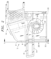
- Figure 2 is a side view of part of a connector assembly comprising a gear member according to the preferred embodiment of this invention;
- Figures 3, 4 and 5 are cross-sectional views through line 3-3 of Figure 2 but including a second connector assembly matable with the first, showing, respectively, different steps during coupling therebetween; and
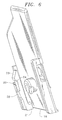
- Figure 6 is an isometric view of part of the connector housing without the gear member showing more clearly the gear retention member.
- Referring first to Figure 2, a
receptacle connector assembly 3 comprising ahousing 4 having amain housing 6 for receiving electrical terminals therein, and agear member 8 comprising apinion 10 withgear teeth 12, and alever arm 14. Thegear member 8 is pivotly attached to anaxis 16 of thehousing 4. The terminals mountable in themain housing section 6 project towards amating face 18 thereof, theconnector assembly 3 being matable to a complementary connector assembly 2 (see Figure 3) similar to the connector assembly 2' of the prior art. The mating connector assembly would thus comprise a rack similar to the rack 6' for engagement with thegear teeth 12 of thepinion 10 during mating and unmating of the connector assemblies. Similarly to the prior art shown in Figure 1, the connector housing 4' would be inserted into a cavity of the complementary connector assembly whereby thepinion 10 and rack would engage causing thegear member 8 to pivot until the fully mated position indicated by thegear lever member 8 shown in dotted lines. - Referring to Figures 1-6, the
connector housing 4 further comprises aresilient latching member 20 attached to themain housing section 6 proximate themating face 18 and extending rearwardly therefrom to afree end 22. Referring to Figures 2 and 3, theresilient retention arm 20 is shown comprising, proximate thefree end 22, aretention shoulder 24 engageable against aretention shoulder 26 of thelever arm 14 when in the fully opened position, and atapered portion 23 for engaging the lever arm during opening thereby biasing the retention arm prior to locking engagement therewith. Intermediate thefree end 22 and attachedend 21, theretention arm 20 comprises acamming portion 28 projecting outwardly therefrom and engageable with awall 30 of the complementary connector housing for biasing of theresilient retention arm 20 out of locking engagement with the leverarm retention shoulder 26 as can be seen in Figure 4. - Figure 4 shows initial insertion of the
connector housing 4 into acavity 32 of acomplementary connector housing 34. During this initial insertion, theretention arms 20 are resiliently biased and release thelever arm 14 such that when thegear teeth 12 engage the rack of the complementary connector, thegear member 8 is free to rotate and allow full insertion of theconnector housing 4 into thecavity 32 as shown in Figure 5. Camming of theresilient retention arms 20 during mating, thus allows a low mating force between the complementary connector assemblies 2, 3 whilst nevertheless providing a very secure retention means that does not suffer from wear during coupling and uncoupling. - Advantageously therefore, the gear member coupling means is securely and reliably maintained in the open position ready for coupling, and automatically released during the coupling without significantly increasing the mating forces required.
Claims (4)
- An electrical connector assembly (3) matable to a complementary connector assembly (2), the connector assembly (3) comprising a housing (4) having a main housing section (6) for receiving electrical terminals therein matable with electrical terminals of a complementary connector assembly (2), the connector housing (4) further comprising a rotatable gear member (8) having a lever arm (14) and a pinion (10) attached to one end of the lever arm, the pinion having gear teeth (12) engageable with a rack of the complementary connector assembly (2), characterized in that the connector housing (4) comprises a resilient retention arm (20) securely locking the gear member (8) to the main housing section (6) in an open position prior to mating, the retention arm (20) comprising a camming portion (28) engageable against a wall portion (30) of the complementary connector assembly (2) during mating for allowing the gear member (8) to rotate.
- The connector assembly of claim 1 characterized in that the retention arm (20) is a cantilevered beam.
- The connector assembly of any preceding claim characterized in that the retention arm (20) is integrally attached to the main housing section (6) proximate a mating face (18) thereof.
- The connector assembly of any preceding claim characterized in that a free end (22) of the retention arm (20) comprises a tapered portion (23) for engaging the lever arm (14) during opening thereof to resiliently bias the retention arm prior to locking engagement therewith.
Applications Claiming Priority (2)
| Application Number | Priority Date | Filing Date | Title |
|---|---|---|---|
| GB9407015A GB9407015D0 (en) | 1994-04-08 | 1994-04-08 | Electrical connector housing assembly with improved locking means |
| GB9407015 | 1994-04-08 |
Publications (3)
| Publication Number | Publication Date |
|---|---|
| EP0676830A2 true EP0676830A2 (en) | 1995-10-11 |
| EP0676830A3 EP0676830A3 (en) | 1998-04-01 |
| EP0676830B1 EP0676830B1 (en) | 2000-12-20 |
Family
ID=10753261
Family Applications (1)
| Application Number | Title | Priority Date | Filing Date |
|---|---|---|---|
| EP95105028A Expired - Lifetime EP0676830B1 (en) | 1994-04-08 | 1995-04-04 | Electrical connector housing assembly with improved locking means |
Country Status (4)
| Country | Link |
|---|---|
| EP (1) | EP0676830B1 (en) |
| JP (1) | JPH07282899A (en) |
| DE (1) | DE69519642T2 (en) |
| GB (1) | GB9407015D0 (en) |
Cited By (6)
| Publication number | Priority date | Publication date | Assignee | Title |
|---|---|---|---|---|
| DE19938930C1 (en) * | 1999-08-17 | 2001-04-12 | Framatome Connectors Int | Electrical connector |
| EP1143566A3 (en) * | 2000-04-04 | 2002-01-30 | Lear Automotive (EEDS) Spain, S.L. | An electrical connector with a pre-assembly retention system |
| DE19704312C2 (en) * | 1997-02-05 | 2002-02-07 | Siemens Ag | Connector with a locking lever |
| DE10135896C2 (en) * | 2000-07-25 | 2003-12-11 | Yazaki Corp | Self-locking lever-type connector |
| GB2436900A (en) * | 2006-04-06 | 2007-10-10 | Kingfisher Plc | Connector with sliding sleeve |
| DE102013019798A1 (en) | 2013-11-27 | 2015-05-28 | Kostal Kontakt Systeme Gmbh | The connector assembly |
Families Citing this family (2)
| Publication number | Priority date | Publication date | Assignee | Title |
|---|---|---|---|---|
| JP3493628B2 (en) * | 2001-01-18 | 2004-02-03 | 日本航空電子工業株式会社 | Connector device |
| JP4338960B2 (en) | 2002-11-19 | 2009-10-07 | 日本電気株式会社 | Optical module locking mechanism |
Family Cites Families (4)
| Publication number | Priority date | Publication date | Assignee | Title |
|---|---|---|---|---|
| GB8625929D0 (en) * | 1986-10-30 | 1986-12-03 | Amp Gmbh | Electrical connector housing assembly |
| DE8700210U1 (en) * | 1987-01-05 | 1987-07-02 | Amp Inc., Harrisburg, Pa. | Connection arrangement with lifting racks |
| FR2684243A1 (en) * | 1991-11-25 | 1993-05-28 | Labinal | IMPROVEMENTS ON ELECTRICAL CONNECTORS WITH LOCKING LEVER. |
| GB9203346D0 (en) * | 1992-02-17 | 1992-04-01 | Amp Gmbh | Electrical connector assembly |
-
1994
- 1994-04-08 GB GB9407015A patent/GB9407015D0/en active Pending
-
1995
- 1995-04-04 EP EP95105028A patent/EP0676830B1/en not_active Expired - Lifetime
- 1995-04-04 DE DE69519642T patent/DE69519642T2/en not_active Expired - Lifetime
- 1995-04-07 JP JP7108077A patent/JPH07282899A/en active Pending
Cited By (8)
| Publication number | Priority date | Publication date | Assignee | Title |
|---|---|---|---|---|
| DE19704312C2 (en) * | 1997-02-05 | 2002-02-07 | Siemens Ag | Connector with a locking lever |
| DE19938930C1 (en) * | 1999-08-17 | 2001-04-12 | Framatome Connectors Int | Electrical connector |
| US6325647B1 (en) | 1999-08-17 | 2001-12-04 | Framatome Connectors International | Electrical plug connector |
| EP1143566A3 (en) * | 2000-04-04 | 2002-01-30 | Lear Automotive (EEDS) Spain, S.L. | An electrical connector with a pre-assembly retention system |
| DE10135896C2 (en) * | 2000-07-25 | 2003-12-11 | Yazaki Corp | Self-locking lever-type connector |
| GB2436900A (en) * | 2006-04-06 | 2007-10-10 | Kingfisher Plc | Connector with sliding sleeve |
| DE102013019798A1 (en) | 2013-11-27 | 2015-05-28 | Kostal Kontakt Systeme Gmbh | The connector assembly |
| DE102013019798B4 (en) | 2013-11-27 | 2021-09-02 | Kostal Kontakt Systeme Gmbh | Connector arrangement |
Also Published As
| Publication number | Publication date |
|---|---|
| GB9407015D0 (en) | 1994-06-01 |
| JPH07282899A (en) | 1995-10-27 |
| DE69519642D1 (en) | 2001-01-25 |
| EP0676830A3 (en) | 1998-04-01 |
| EP0676830B1 (en) | 2000-12-20 |
| DE69519642T2 (en) | 2001-05-23 |
Similar Documents
| Publication | Publication Date | Title |
|---|---|---|
| US5833484A (en) | Connector with pivotable coupling lever | |
| US5383794A (en) | Latch actuator for a connector | |
| EP0966067B1 (en) | Lever type electrical connector | |
| JP2762347B2 (en) | Hooded electrical connector with terminal position assurance means | |
| US4178051A (en) | Latch/eject pin header | |
| EP1955414B1 (en) | Lever type electrical connector | |
| JP3235489B2 (en) | Block connector | |
| JP2525502B2 (en) | Electrical connector | |
| EP0501502B1 (en) | Low insertion/withdrawal-force connector | |
| EP0848458B1 (en) | Connector with engagement detection means | |
| JP3023868B2 (en) | Lever connection type connector | |
| EP1130691B1 (en) | Lever-type connector | |
| EP0372766B1 (en) | Connector with removable latch block and removable latch block therefor | |
| EP0676830B1 (en) | Electrical connector housing assembly with improved locking means | |
| US6102717A (en) | Cam mechanism for attaching and detaching interconnecting structures with a low insertion force | |
| US5269699A (en) | Lockable electrical connector assembly | |
| JPH0755830Y2 (en) | Connector lock eject mechanism | |
| JP3038130B2 (en) | Lever connection type connector | |
| GB2322979A (en) | Lif connector | |
| EP0568018B1 (en) | Connector | |
| US5928014A (en) | Electrical connector having a pair of connector housings | |
| JPH0256875A (en) | Connector | |
| JP2912471B2 (en) | Two-piece connector | |
| US6296510B1 (en) | Electrical connector with lever type latch means | |
| JP2940894B2 (en) | Lever connector |
Legal Events
| Date | Code | Title | Description |
|---|---|---|---|
| PUAI | Public reference made under article 153(3) epc to a published international application that has entered the european phase |
Free format text: ORIGINAL CODE: 0009012 |
|
| AK | Designated contracting states |
Kind code of ref document: A2 Designated state(s): DE ES FR GB IT SE |
|
| PUAL | Search report despatched |
Free format text: ORIGINAL CODE: 0009013 |
|
| AK | Designated contracting states |
Kind code of ref document: A3 Designated state(s): DE ES FR GB IT SE |
|
| 17P | Request for examination filed |
Effective date: 19980930 |
|
| GRAG | Despatch of communication of intention to grant |
Free format text: ORIGINAL CODE: EPIDOS AGRA |
|
| 17Q | First examination report despatched |
Effective date: 20000208 |
|
| GRAG | Despatch of communication of intention to grant |
Free format text: ORIGINAL CODE: EPIDOS AGRA |
|
| GRAH | Despatch of communication of intention to grant a patent |
Free format text: ORIGINAL CODE: EPIDOS IGRA |
|
| GRAH | Despatch of communication of intention to grant a patent |
Free format text: ORIGINAL CODE: EPIDOS IGRA |
|
| GRAA | (expected) grant |
Free format text: ORIGINAL CODE: 0009210 |
|
| AK | Designated contracting states |
Kind code of ref document: B1 Designated state(s): DE ES FR GB IT SE |
|
| PG25 | Lapsed in a contracting state [announced via postgrant information from national office to epo] |
Ref country code: SE Free format text: THE PATENT HAS BEEN ANNULLED BY A DECISION OF A NATIONAL AUTHORITY Effective date: 20001220 Ref country code: IT Free format text: LAPSE BECAUSE OF FAILURE TO SUBMIT A TRANSLATION OF THE DESCRIPTION OR TO PAY THE FEE WITHIN THE PRESCRIBED TIME-LIMIT;WARNING: LAPSES OF ITALIAN PATENTS WITH EFFECTIVE DATE BEFORE 2007 MAY HAVE OCCURRED AT ANY TIME BEFORE 2007. THE CORRECT EFFECTIVE DATE MAY BE DIFFERENT FROM THE ONE RECORDED. Effective date: 20001220 Ref country code: ES Free format text: THE PATENT HAS BEEN ANNULLED BY A DECISION OF A NATIONAL AUTHORITY Effective date: 20001220 |
|
| REF | Corresponds to: |
Ref document number: 69519642 Country of ref document: DE Date of ref document: 20010125 |
|
| ET | Fr: translation filed | ||
| PLBE | No opposition filed within time limit |
Free format text: ORIGINAL CODE: 0009261 |
|
| STAA | Information on the status of an ep patent application or granted ep patent |
Free format text: STATUS: NO OPPOSITION FILED WITHIN TIME LIMIT |
|
| 26N | No opposition filed | ||
| REG | Reference to a national code |
Ref country code: GB Ref legal event code: IF02 |
|
| PGFP | Annual fee paid to national office [announced via postgrant information from national office to epo] |
Ref country code: GB Payment date: 20050330 Year of fee payment: 11 |
|
| PG25 | Lapsed in a contracting state [announced via postgrant information from national office to epo] |
Ref country code: GB Free format text: LAPSE BECAUSE OF NON-PAYMENT OF DUE FEES Effective date: 20060404 |
|
| GBPC | Gb: european patent ceased through non-payment of renewal fee |
Effective date: 20060404 |
|
| PGFP | Annual fee paid to national office [announced via postgrant information from national office to epo] |
Ref country code: DE Payment date: 20140429 Year of fee payment: 20 Ref country code: FR Payment date: 20140417 Year of fee payment: 20 |
|
| REG | Reference to a national code |
Ref country code: DE Ref legal event code: R071 Ref document number: 69519642 Country of ref document: DE |