EP0676829A2 - Field repairable electrical connector - Google Patents
Field repairable electrical connector Download PDFInfo
- Publication number
- EP0676829A2 EP0676829A2 EP95250088A EP95250088A EP0676829A2 EP 0676829 A2 EP0676829 A2 EP 0676829A2 EP 95250088 A EP95250088 A EP 95250088A EP 95250088 A EP95250088 A EP 95250088A EP 0676829 A2 EP0676829 A2 EP 0676829A2
- Authority
- EP
- European Patent Office
- Prior art keywords
- male
- sheaths
- female
- face surface
- coupling member
- Prior art date
- Legal status (The legal status is an assumption and is not a legal conclusion. Google has not performed a legal analysis and makes no representation as to the accuracy of the status listed.)
- Granted
Links
Images

Classifications
-
- H—ELECTRICITY
- H01—ELECTRIC ELEMENTS
- H01R—ELECTRICALLY-CONDUCTIVE CONNECTIONS; STRUCTURAL ASSOCIATIONS OF A PLURALITY OF MUTUALLY-INSULATED ELECTRICAL CONNECTING ELEMENTS; COUPLING DEVICES; CURRENT COLLECTORS
- H01R13/00—Details of coupling devices of the kinds covered by groups H01R12/70 or H01R24/00 - H01R33/00
- H01R13/46—Bases; Cases
- H01R13/52—Dustproof, splashproof, drip-proof, waterproof, or flameproof cases
- H01R13/523—Dustproof, splashproof, drip-proof, waterproof, or flameproof cases for use under water
-
- H—ELECTRICITY
- H01—ELECTRIC ELEMENTS
- H01R—ELECTRICALLY-CONDUCTIVE CONNECTIONS; STRUCTURAL ASSOCIATIONS OF A PLURALITY OF MUTUALLY-INSULATED ELECTRICAL CONNECTING ELEMENTS; COUPLING DEVICES; CURRENT COLLECTORS
- H01R13/00—Details of coupling devices of the kinds covered by groups H01R12/70 or H01R24/00 - H01R33/00
- H01R13/46—Bases; Cases
- H01R13/52—Dustproof, splashproof, drip-proof, waterproof, or flameproof cases
-
- H—ELECTRICITY
- H01—ELECTRIC ELEMENTS
- H01R—ELECTRICALLY-CONDUCTIVE CONNECTIONS; STRUCTURAL ASSOCIATIONS OF A PLURALITY OF MUTUALLY-INSULATED ELECTRICAL CONNECTING ELEMENTS; COUPLING DEVICES; CURRENT COLLECTORS
- H01R13/00—Details of coupling devices of the kinds covered by groups H01R12/70 or H01R24/00 - H01R33/00
- H01R13/46—Bases; Cases
- H01R13/502—Bases; Cases composed of different pieces
Definitions
- This invention relates generally to a field repairable electrical connector that is adaptable for use in either underwater or dry land applications, and more particularly to such a connector having a removable, resiliently compressible coupling member disposed between rigid male and female body members.
- an underwater electrical connector having a male member formed of a rigid plastic material that has a plurality of pins partially enclosed by a sheath formed of the same rigid plastic material.
- the underwater connector has a female member formed of an elastomeric material and has a plurality of passageways formed in the elastomeric material in which a portion of the passageway sealably surrounds the rigid sheaths of the male member. This arrangement provides an excellent waterproof seal to exclude moisture from the connection between the pin and a socket encapsulated within the female member.
- this construction makes it necessary to enclose the separated wires of the cable bundle, and the individual connections between the wires and the sockets in the female connector, in a single molded component.
- the repair must necessarily include the cable to which the female member is molded.
- the sockets are embedded in a relatively soft, deformable material, it is possible for the sockets to become slightly misaligned, permitting the sockets to move, or even bend, during insertion of the pins and subsequent use of the connector. This characteristic, while desirable for sealing, makes it more difficult, over a period of time, to maintain the desirable alignment of the sockets with a respective pin of the male connector.
- Other electrical connectors have male or female members, or both, in which the respective pins and sockets are encased in a relatively soft, elastomeric body that is surrounded by a hard plastic or metallic case.
- body and case are constructed of materials having different physical characteristics, even though they are initially bonded together, the components are prone to subsequent separation and failure.
- the present invention is directed to overcoming the problems set forth above. It is desirable to have an electrical connector that is easily repairable in the field and is useable in both underwater and dry land environments. For such underwater uses, it is desirable that the sealing capability of the connector increases in response to an increase in the water pressure imposed on the connector at greater depths. It is also desirable to have such an electrical connector in which both the male and female components of the connector are each formed of a single, rigid material.
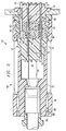
- Fig. 1 is a longitudinal cross section of an electrical connector embodying the present invention, showing the components of the connector in unassembled, spaced apart relationship.
- Fig. 2 is a longitudinal cross section of the electrical connector shown in Fig. 1, showing the components of the connector in assembled relationship.
- an electrical connector 10 has a male member 12 and a female member 14, both of which have a body portion 16,18 respectively, that is formed of a single, hard, rigid, electrically nonconductive material.
- the material is an injection moldable glass filled urethane.
- the male member 12 also includes a plurality of electrically conductive pins 20 that are arranged in a predetermined pattern within a mold cavity prior to injection molding the body 16. Simultaneously with molding the body 16, a sheath 22 is formed about a portion of each of the pins 20 thereby, through shrinkage during solidification after molding, tightly encapsulating each of the pins not only within the body 16 but also within a respective sheath 22.
- the sheaths 22 extend outwardly from a first face surface 24 of the body 16, which also has a second face surface 26 spaced from the first face surface 24.
- Each of the pins 20 have a first portion 28 completely encapsulated within the body 16 and a respective one of the sheaths 22, an exposed second portion 30 extending outwardly from a distal end of the sheath 22, and an exposed third portion 32 extending outwardly from the second face surface 26 of the body 16.
- the outer surface of the first, or encapsulated, portion 28 of the pins 20 preferably have a plurality of inwardly extending annular grooves to aid in the retention of the pins 20 in the body 16 and to improve sealing of the body 16 and sheath 22 around each of the pins 20.
- the third portion 32 of the pins 20 preferably have a socket formed therein for receiving the pin end of an insertable/removable solder lug that is soldered to a wire conductor (not shown).
- solder lug may be directly formed on the outer end of the pin 20.
- the body portion 18 of the female member 14 has a first face surface 34, a second face surface 36 spaced from the first face surface 34, and a plurality of integrally formed sheaths 38 extending outwardly from the first face surface 34.
- the female member 14 also includes a plurality of electrically conductive sockets 40 that are arranged in the same predetermined pattern as the pins 20. Each of the sockets 40 are shaped to receive substantially all of the exposed second portion 30 of the pins 20 and grip the pins so that they are maintained in electrically conductive contact with the socket 40.
- the pin receiving portions of the sockets 40 are shaped so that it has a depth slightly greater than the length of the exposed first portion 28 of the pins 20 to assure that the pins will not “bottom out” in socket. Also, it is desirable that the end of the sheaths 22,38 surrounding the pins and sockets be slightly spaced apart to preclude potential wear or damage to the sheaths.
- Each of the sockets 40 have a first portion 42 in which the outer perimeter of the socket is completely encapsulated within the body 18 and a respective one of the sheaths 38 of the female member 14, and a second portion 44 that extends outwardly from the second face surface 36 of the body 18.
- a plurality of annular grooves are provided along at least a portion of the length of the outer surface of the sockets 40 to assure retention of the socket in the body 18 and enhance sealing between the socket 40 and the body.
- the second portion 44 of the sockets 40 preferably have a solder lug formed on an outer end for attachment of a wire conductor (not shown).
- the electrical connector 10 embodying the present invention also has an elastomeric coupling member 46 that is preferably formed of an injection moldable, resiliently compressible and electrically nonconductive material such as thermoplastic rubber.
- an injection moldable, resiliently compressible and electrically nonconductive material such as thermoplastic rubber.
- thermoplastic rubber elastomeric material
- a blend of polyethylene and neoprene rubber provides the resilience and compressibility desirable for sealing the sheaths as described below in more detail.
- the coupling member 46 has a hardness of from about 40 to about 70 durometer as measured by the Shore A scale.
- the coupling member 46 has a first face surface 48 that is shaped so that it is able to tightly abut and seal against the first face surface 24 of the male member 12, and a second face surface 50 that is shaped to enable it to abut, in a sealing relationship, against the first face surface 34 of the female member 14.
- the coupling member 46 also has a plurality of passageways 52 extending between the first and second face surfaces 48,50 of the coupling 46.
- the passageways 52 are arranged in the same predetermined pattern as the pins 20 and the sockets 40. It is also desirable that the coupling member 46 have a locator hole 54 adapted to receive a locator pin 56, preferably provided on the female member 14, to aid radial orientation of the coupling 46 when connecting the components together.
- Each of the passageways 52 have an internal wall surface that is shaped to receive and completely surround each of the sheaths 22,38 on the body portions 16,18 of the male and female members 12,14.
- the internal wall surfaces may advantageously have a smooth cylindrical surface with an internal diameter substantially the same as, or even slightly greater than, the external diameter of the sheaths 20,40.
- each of the passageways 52 in the preferred embodiment of the present invention have a generally circular cross sectional shape in which at least one, and desirably a plurality of, annular alternating grooves 58 and ridges 60 are formed.
- the ridges 60 preferably have an internal diameter slightly less than the diameter of the sheaths 22,38 so that, when the sheaths are inserted into the passageways 52, each of the ridges 60 form a lip, or O-ring type, seal about the circumference of each sheath.
- the ridges 60 clears water from the pin-socket connection.
- each of the sheaths 22,38 have an external diameter of 0.200 inches (0.079 cm), and each of the ridges 60 have a diameter of 0.150 inches (0.059 cm).
- the annular grooves 58 between the ridges 60 in the passageways 52 have a diameter of 0.205 inches (0.081 cm) which is slightly greater than the external diameter of the sheaths 22,38 .
- underwater sealing of the electrical connection between a pin 20 and a socket 40 is not dependent upon forming a face seal between the coupling member 46 and either the male or the female member 12,14.
- an essentially isostatic pressure such as that applied by subsurface water pressure, will compress an outer circumferential surface 62 of the elastomeric coupling 46 and increase the pressure that the internally disposed ridges 60 apply against each of the sheaths 22,38. That is, the sealing pressure imposed by the passageways 52 about each of the sheaths 22,38 will increase in response to increased pressure on the outer circumferential surface 62.
- the internal passageways 52 would preferably be formed to a diameter of, for example, about 0.210 inches (0.083 cm).
- the connector 10 can be adapted for use in applications having very different environmental requirements.
- the coupling member 46 is reversible, i.e., it can be installed with either face 48,50 abutting either the male member 12 or the female member 14.
- the sheaths 22 surrounding the pins 20 have a length of 0.581 inch (1.48 cm) and the sheaths 38 surrounding the sockets 40 have a length of 0.400 inch (1.02 cm).
- the total combined length of the sheaths 22,38 is 0.981 inches (2.49 cm).
- the length of the coupling member 46, and accordingly the length of the passageways 52 in the coupling member is 1.081 inches (2.75 cm). Therefore, upon assembly, as described below in additional detail, there will be a gap, or "stand-of distance", of about 0.100 inch (.25 cm) between the ends of the sheaths 22,38.
- the length of the sheaths 22 surrounding the pins 20 is longer than the length of the sheaths 38 formed around the sockets 40. Therefore, there is more contact surface between the pin sheaths 22 and the internal surfaces of the passageways 52 in the coupling 46 than between the socket sheaths 38 and the passageways. Because of the greater contact area, the coupling member 46 will, upon disassembly, be captured by and retained with the male member 12. Also, because each of the passageways 52 is longer than the combined length of the pin sheath 22 and the exposed pin portion 30, each of the exposed pin portions 30 are completely surrounded and protects the pins 20 from damage during handling or repair operations.
- the electrical connector 10 includes a means 64 for maintaining the first and second face surfaces 48,50 of the coupling 46 in respective abutting contact with the first face surfaces 24,34 of the male and female members 12,14,
- the means 64 includes a female adaptor member 66 having internal threads 68 which are threadably engageable with a plurality of threads 70 provided on a circumferential surface of the female member 14.
- the female adaptor 66 secures the female member 14 in a fixed mounted position against a wall or case surface by drawing an annular shoulder on the circumference of the female member against the wall in response to tightening the threaded connection between the adaptor 66 and female member 14.
- a male adaptor member 72 has internal threads 74, formed adjacent one end, which are adapted to threadably engage a plurality of external threads 76 formed on the male member 12.
- the male adaptor 76 preferably has a provision for receiving a cable containing a plurality of wires in the other end and for sealing the entrance of the cable into the male adaptor 72.
- the cable may be directly molded to the male member 12, thereby forming a single integrated component.
- the means 64 for maintaining the coupling 46 and the male and female members 12,14 in their respective abutting relationships also includes a rigid outer shell 78 that has a plurality of internal threads 80 disposed at one end of the shell that are adapted to mate with a plurality of external threads 82 provided on the female adaptor member 66.
- the shell 78 also has an internally disposed groove 84 adjacent the other end which is adapted to receive a snap ring 86 that, when the connector 10 is assembled as shown in Fig. 2, abuts a shoulder 88 formed on the outer surface of the male adapter member 72. It is also desirable that the outer shell 78 have a plurality of open slots 90 extending through the periphery of the shell.
- the slots 90 advantageously provide an aid to gripping and turning the shell during assembly or disassembly of the connector, and additionally provide an important self cleaning action. For these purposes, it is even desirable that at least part of the threaded portion of the outer shell 78 also have open slots 90 through the shell.
- the female adaptor member 66, the male adaptor member 72, and the shell 78 are all constructed of a rigid plastic material, such as fiberglass filled polyurethane, that is electrically nonconductive, resistant to corrosion, and easily formable by conventional molding techniques.
- the electrical connector 10 is assembled, as shown in Fig. 2, by first inserting the female member 14 through one side of an aperture 92 in a data box or control panel, with a shoulder of the female member having an o-ring seal disposed therein in contact with the panel.
- the female adapter member 66 is then threaded onto the female member 14 and tightened against the mounting wall or panel. This effectively locks the female member 14 in place with respect to the fixed wall surface.
- the elastomeric coupling member 46 is then inserted over the pins 20 and the sheaths 22 of the male member 12. Next, while not entirely necessary because of the below described subsequent drawing of the element together, the coupling member 46 is desirably pushed onto the male member 12 until the second face surface 50 of the coupling member is in abutting contact with the face surface 24 of the body member 16.
- the male adapter member 72 is then joined with the assembled coupling and male members 46,12 by threading the external threads 76 on the male member into the internal threads 74 in the male adapter member 72.
- the individual lead wires from a line cable assembly are attached to the ends, i.e., the third portion 32, of the pins 20.
- the assembled coupling member 46, male member 12 with wires attached, and male adaptor member 72 are then inserted, as a unit, through the left end (as viewed in Figs. 1 and 2) of the outer shell 78 to a position at which the shoulder 88 on the male adapter membe r 72 passes to the right of the groove 84 in the outer shell 78.
- the snap ring 86 is then inserted into the groove 84 which coacts with the shoulder 84 to prevent leftward movement of the male adaptor member 72 and the components previously assembled therewith.
- the coupling member 46, male member 12 and the male adaptor 72 are rotated, if needed, to align the locator hole 54 in the coupling member with the locator pin 56.
- the outer shell 78 is then moved into contact with the female adaptor member 66 and rotated to engage the internal threads 80 on the outer shell with the external threads 82 on the female adapter member.
- an anti-friction fiber washer is prepositioned between an inwardly extending shoulder 94 of the outer shell and an outwardly extending flange on the coupling member 46. Tightening the outer shell 78 against the female adapter member 66 will draw the male and female members 12,14, toward the coupling member 46 that is positioned between the male and female members.
- the second face surface 50 of the coupling member 46 and the first face surface 34 of the female member 14, and the first face surface 24 of the male member 12 and the first face surface 48 of the coupling member 46 are in respective abutting contact with each other.
- the exposed pins 20 of the male member 12 captured by, and maintained in electrical contact with, the sockets 40 and the sheaths 22,38 of both the male and female members 12,14 are effectively sealed by the passageways 52 of the resiliently compressible coupling member 46.
- the length of the sheaths 22 of the male member 12 are longer than sheaths 38 of the female member 14.
- the inwardly extending shoulder 94 formed on the outer shell 78 will pull the coupling member 46 away from of the female member 14.
- the coupling member 46 is captured by, and retained on, the male member 12. This makes subsequent reassembly, particularly underwater, easier because it eliminates the need to separately orient and install the coupling member 46 on the male member 12.
- the coupling member 46 extends beyond the ends of the pins 20 of the male member 12, thereby protecting the pins when the connector 10 is in an uncoupled state.
- the assembled electrical connector 10 is easily disassembled, in the field, by reversal of the above described assembly procedure.
- the connector 10 can be disassembled and reassembled for service, even underwater if necessary.
- the coupling member 46 and the male and female members 12,14 are immediately field replaceable.
- the male and female member 12,14 may be individually replaced by removing the solder tabs from the socket connection provides on the ends of the pins 20 and the sockets 40.
- the electrical connector 10 is used as a line connector, i.e., without one of the members mounted in a box or to a wall.
- a line connector i.e., without one of the members mounted in a box or to a wall.
- Other applications, changes and modifications of the above described electrical connector may similarly be made without departing from the spirit and scope of the present invention.
- the present invention is particularly useful in applications that require sealing of electrical connections against adverse environmental conditions such as underwater data acquisition and transmission systems, subsurface or ground level instruments subjected to adverse operational and atmospheric environments such as seismic exploration applications, and other uses where it is desirable to protect the electrical contact portions of the connector.
- the present invention because of the resilient coupling provided between rigid components housing the electrical contact elements, also has important uses in applications where the electrical connector is subjected to high vibration or shock, such as in rough terrain vehicles and earthmoving machines.
- the electrical connector 10 embodying the present invention comprises individual components that can be disassembled, repaired or replaced, and reassembled, even underwater, without the need of special tools or repair facilities.
- the electrical connector described above and defined by the claims is particularly suited for use in remote geographical locations where repair facilities are not readily available.
Abstract
Description
- This invention relates generally to a field repairable electrical connector that is adaptable for use in either underwater or dry land applications, and more particularly to such a connector having a removable, resiliently compressible coupling member disposed between rigid male and female body members.
- A long standing problem with electrical connectors in general, and specifically with sealed connectors intended for use in underwater applications, has been the inability to service and repair such connectors in the field. In general, such connectors must be disassembled in a repair shop and molded component assemblies replaced with new components. Furthermore, to make an electrical connection waterproof, it has heretofore been necessary that at least one part of the male or female member of the connector be formed of, or equipped with, a relatively soft, deformable element, to provide a seal around the electrically conductive parts of the connector or, alternatively, enclose the entire connector within a sealed case.
- For example, copending U.S. Patent Application No. 08/134,075, filed October 8, 1993 by the inventor of the present invention, discloses an underwater electrical connector having a male member formed of a rigid plastic material that has a plurality of pins partially enclosed by a sheath formed of the same rigid plastic material. The underwater connector has a female member formed of an elastomeric material and has a plurality of passageways formed in the elastomeric material in which a portion of the passageway sealably surrounds the rigid sheaths of the male member. This arrangement provides an excellent waterproof seal to exclude moisture from the connection between the pin and a socket encapsulated within the female member. However, this construction makes it necessary to enclose the separated wires of the cable bundle, and the individual connections between the wires and the sockets in the female connector, in a single molded component. Thus, it is not possible, in the field, to replace only the female connector because the repair must necessarily include the cable to which the female member is molded. Also, since the sockets are embedded in a relatively soft, deformable material, it is possible for the sockets to become slightly misaligned, permitting the sockets to move, or even bend, during insertion of the pins and subsequent use of the connector. This characteristic, while desirable for sealing, makes it more difficult, over a period of time, to maintain the desirable alignment of the sockets with a respective pin of the male connector.
- Other electrical connectors have male or female members, or both, in which the respective pins and sockets are encased in a relatively soft, elastomeric body that is surrounded by a hard plastic or metallic case. When the body and case are constructed of materials having different physical characteristics, even though they are initially bonded together, the components are prone to subsequent separation and failure.
- The present invention is directed to overcoming the problems set forth above. It is desirable to have an electrical connector that is easily repairable in the field and is useable in both underwater and dry land environments. For such underwater uses, it is desirable that the sealing capability of the connector increases in response to an increase in the water pressure imposed on the connector at greater depths. It is also desirable to have such an electrical connector in which both the male and female components of the connector are each formed of a single, rigid material.
- Fig. 1 is a longitudinal cross section of an electrical connector embodying the present invention, showing the components of the connector in unassembled, spaced apart relationship.
- Fig. 2 is a longitudinal cross section of the electrical connector shown in Fig. 1, showing the components of the connector in assembled relationship.
- In the preferred embodiment of the present invention, an
electrical connector 10 has amale member 12 and afemale member 14, both of which have abody portion - The
male member 12 also includes a plurality of electricallyconductive pins 20 that are arranged in a predetermined pattern within a mold cavity prior to injection molding thebody 16. Simultaneously with molding thebody 16, asheath 22 is formed about a portion of each of thepins 20 thereby, through shrinkage during solidification after molding, tightly encapsulating each of the pins not only within thebody 16 but also within arespective sheath 22. Thesheaths 22 extend outwardly from afirst face surface 24 of thebody 16, which also has asecond face surface 26 spaced from thefirst face surface 24. - Each of the
pins 20 have afirst portion 28 completely encapsulated within thebody 16 and a respective one of thesheaths 22, an exposedsecond portion 30 extending outwardly from a distal end of thesheath 22, and an exposedthird portion 32 extending outwardly from thesecond face surface 26 of thebody 16. The outer surface of the first, or encapsulated,portion 28 of thepins 20 preferably have a plurality of inwardly extending annular grooves to aid in the retention of thepins 20 in thebody 16 and to improve sealing of thebody 16 and sheath 22 around each of thepins 20. Thethird portion 32 of thepins 20 preferably have a socket formed therein for receiving the pin end of an insertable/removable solder lug that is soldered to a wire conductor (not shown). Alternatively, although less desirable from a field repair aspect, the solder lug may be directly formed on the outer end of thepin 20. - The
body portion 18 of thefemale member 14 has afirst face surface 34, asecond face surface 36 spaced from thefirst face surface 34, and a plurality of integrally formed sheaths 38 extending outwardly from thefirst face surface 34. Thefemale member 14 also includes a plurality of electricallyconductive sockets 40 that are arranged in the same predetermined pattern as thepins 20. Each of thesockets 40 are shaped to receive substantially all of the exposedsecond portion 30 of thepins 20 and grip the pins so that they are maintained in electrically conductive contact with thesocket 40. In the preferred embodiment of the present invention, the pin receiving portions of thesockets 40 are shaped so that it has a depth slightly greater than the length of the exposedfirst portion 28 of thepins 20 to assure that the pins will not "bottom out" in socket. Also, it is desirable that the end of thesheaths 22,38 surrounding the pins and sockets be slightly spaced apart to preclude potential wear or damage to the sheaths. - Each of the
sockets 40 have afirst portion 42 in which the outer perimeter of the socket is completely encapsulated within thebody 18 and a respective one of the sheaths 38 of thefemale member 14, and asecond portion 44 that extends outwardly from thesecond face surface 36 of thebody 18. Preferably, a plurality of annular grooves are provided along at least a portion of the length of the outer surface of thesockets 40 to assure retention of the socket in thebody 18 and enhance sealing between thesocket 40 and the body. Thesecond portion 44 of thesockets 40 preferably have a solder lug formed on an outer end for attachment of a wire conductor (not shown). - The
electrical connector 10 embodying the present invention also has anelastomeric coupling member 46 that is preferably formed of an injection moldable, resiliently compressible and electrically nonconductive material such as thermoplastic rubber. In particular, it has been found that a blend of polyethylene and neoprene rubber, provides the resilience and compressibility desirable for sealing the sheaths as described below in more detail. Preferably, after curing, thecoupling member 46 has a hardness of from about 40 to about 70 durometer as measured by the Shore A scale. - The
coupling member 46 has afirst face surface 48 that is shaped so that it is able to tightly abut and seal against thefirst face surface 24 of themale member 12, and asecond face surface 50 that is shaped to enable it to abut, in a sealing relationship, against thefirst face surface 34 of thefemale member 14. - The
coupling member 46 also has a plurality ofpassageways 52 extending between the first andsecond face surfaces coupling 46. Thepassageways 52 are arranged in the same predetermined pattern as thepins 20 and thesockets 40. It is also desirable that thecoupling member 46 have alocator hole 54 adapted to receive alocator pin 56, preferably provided on thefemale member 14, to aid radial orientation of thecoupling 46 when connecting the components together. - Each of the
passageways 52 have an internal wall surface that is shaped to receive and completely surround each of thesheaths 22,38 on thebody portions female members sheaths - In underwater uses however, it is desirable to provide a tight waterproof seal about the
sheaths passageways 52 in the preferred embodiment of the present invention have a generally circular cross sectional shape in which at least one, and desirably a plurality of, annularalternating grooves 58 andridges 60 are formed. Theridges 60 preferably have an internal diameter slightly less than the diameter of thesheaths 22,38 so that, when the sheaths are inserted into thepassageways 52, each of theridges 60 form a lip, or O-ring type, seal about the circumference of each sheath. Importantly, when theconnector 10 is mated, or connected, underwater, theridges 60 clears water from the pin-socket connection. It has also been found that if, after initial connection of the components, the components are subsequently slightly separated, e.g., moved apart about 1/4 inch (0.64 cm), and then rejoined, the ridges coact to provide a pumping action that further clears water from the pin-socket joint. - In an actual construction of the
connector 10 embodying the present invention, each of thesheaths 22,38 have an external diameter of 0.200 inches (0.079 cm), and each of theridges 60 have a diameter of 0.150 inches (0.059 cm). Theannular grooves 58 between theridges 60 in thepassageways 52 have a diameter of 0.205 inches (0.081 cm) which is slightly greater than the external diameter of thesheaths 22,38. - Thus, it can be seen that underwater sealing of the electrical connection between a
pin 20 and asocket 40 is not dependent upon forming a face seal between thecoupling member 46 and either the male or thefemale member ridges 60 in each of thepassageways 52, the application of an essentially isostatic pressure, such as that applied by subsurface water pressure, will compress an outercircumferential surface 62 of theelastomeric coupling 46 and increase the pressure that the internally disposedridges 60 apply against each of thesheaths 22,38. That is, the sealing pressure imposed by thepassageways 52 about each of thesheaths 22,38 will increase in response to increased pressure on the outercircumferential surface 62. - As discussed above, if sealing against moisture or water is not required, such as in dry desert applications, it is desirable to form a single smooth cylindrical wall in the
passageway 52 that is somewhat greater than the external diameter of thesheaths 22,38. For example, in the above described actual construction in which the external diameter of the sheaths was 0.200 inches (0.079 cm) theinternal passageways 52 would preferably be formed to a diameter of, for example, about 0.210 inches (0.083 cm). - Thus, it can be seen that by simply changing the
coupling member 46, i.e., selecting a coupling members having either smooth wall or ridged wall passageways, theconnector 10 can be adapted for use in applications having very different environmental requirements. Also, if the pins andsockets coupling member 46 is reversible, i.e., it can be installed with eitherface male member 12 or thefemale member 14. - In the above described actual construction, the
sheaths 22 surrounding thepins 20 have a length of 0.581 inch (1.48 cm) and the sheaths 38 surrounding thesockets 40 have a length of 0.400 inch (1.02 cm). Thus, the total combined length of thesheaths 22,38 is 0.981 inches (2.49 cm). The length of thecoupling member 46, and accordingly the length of thepassageways 52 in the coupling member is 1.081 inches (2.75 cm). Therefore, upon assembly, as described below in additional detail, there will be a gap, or "stand-of distance", of about 0.100 inch (.25 cm) between the ends of thesheaths 22,38. - Importantly, the length of the
sheaths 22 surrounding thepins 20 is longer than the length of the sheaths 38 formed around thesockets 40. Therefore, there is more contact surface between thepin sheaths 22 and the internal surfaces of thepassageways 52 in thecoupling 46 than between the socket sheaths 38 and the passageways. Because of the greater contact area, thecoupling member 46 will, upon disassembly, be captured by and retained with themale member 12. Also, because each of thepassageways 52 is longer than the combined length of thepin sheath 22 and the exposedpin portion 30, each of the exposedpin portions 30 are completely surrounded and protects thepins 20 from damage during handling or repair operations. Preferably, theelectrical connector 10 includes ameans 64 for maintaining the first and second face surfaces 48,50 of thecoupling 46 in respective abutting contact with the first face surfaces 24,34 of the male andfemale members means 64 includes afemale adaptor member 66 havinginternal threads 68 which are threadably engageable with a plurality ofthreads 70 provided on a circumferential surface of thefemale member 14. Thefemale adaptor 66 secures thefemale member 14 in a fixed mounted position against a wall or case surface by drawing an annular shoulder on the circumference of the female member against the wall in response to tightening the threaded connection between theadaptor 66 andfemale member 14. - In similar fashion, a
male adaptor member 72 hasinternal threads 74, formed adjacent one end, which are adapted to threadably engage a plurality ofexternal threads 76 formed on themale member 12. Themale adaptor 76 preferably has a provision for receiving a cable containing a plurality of wires in the other end and for sealing the entrance of the cable into themale adaptor 72. Alternatively, although less desirable for field repairs, the cable may be directly molded to themale member 12, thereby forming a single integrated component. - The means 64 for maintaining the
coupling 46 and the male andfemale members outer shell 78 that has a plurality ofinternal threads 80 disposed at one end of the shell that are adapted to mate with a plurality ofexternal threads 82 provided on thefemale adaptor member 66. Theshell 78 also has an internally disposedgroove 84 adjacent the other end which is adapted to receive asnap ring 86 that, when theconnector 10 is assembled as shown in Fig. 2, abuts ashoulder 88 formed on the outer surface of themale adapter member 72. It is also desirable that theouter shell 78 have a plurality ofopen slots 90 extending through the periphery of the shell. Theslots 90 advantageously provide an aid to gripping and turning the shell during assembly or disassembly of the connector, and additionally provide an important self cleaning action. For these purposes, it is even desirable that at least part of the threaded portion of theouter shell 78 also haveopen slots 90 through the shell. - Preferably the
female adaptor member 66, themale adaptor member 72, and theshell 78 are all constructed of a rigid plastic material, such as fiberglass filled polyurethane, that is electrically nonconductive, resistant to corrosion, and easily formable by conventional molding techniques. - The
electrical connector 10 is assembled, as shown in Fig. 2, by first inserting thefemale member 14 through one side of anaperture 92 in a data box or control panel, with a shoulder of the female member having an o-ring seal disposed therein in contact with the panel. Thefemale adapter member 66 is then threaded onto thefemale member 14 and tightened against the mounting wall or panel. This effectively locks thefemale member 14 in place with respect to the fixed wall surface. - The
elastomeric coupling member 46 is then inserted over thepins 20 and thesheaths 22 of themale member 12. Next, while not entirely necessary because of the below described subsequent drawing of the element together, thecoupling member 46 is desirably pushed onto themale member 12 until thesecond face surface 50 of the coupling member is in abutting contact with theface surface 24 of thebody member 16. - The
male adapter member 72 is then joined with the assembled coupling andmale members external threads 76 on the male member into theinternal threads 74 in themale adapter member 72. Prior to this last step, unless already connected, the individual lead wires from a line cable assembly are attached to the ends, i.e., thethird portion 32, of thepins 20. - The assembled
coupling member 46,male member 12 with wires attached, andmale adaptor member 72 are then inserted, as a unit, through the left end (as viewed in Figs. 1 and 2) of theouter shell 78 to a position at which theshoulder 88 on themale adapter member 72 passes to the right of thegroove 84 in theouter shell 78. Thesnap ring 86 is then inserted into thegroove 84 which coacts with theshoulder 84 to prevent leftward movement of themale adaptor member 72 and the components previously assembled therewith. - The
coupling member 46,male member 12 and themale adaptor 72 are rotated, if needed, to align thelocator hole 54 in the coupling member with thelocator pin 56. Theouter shell 78 is then moved into contact with thefemale adaptor member 66 and rotated to engage theinternal threads 80 on the outer shell with theexternal threads 82 on the female adapter member. Preferably, an anti-friction fiber washer is prepositioned between an inwardly extendingshoulder 94 of the outer shell and an outwardly extending flange on thecoupling member 46. Tightening theouter shell 78 against thefemale adapter member 66 will draw the male andfemale members coupling member 46 that is positioned between the male and female members. Thus, after tightening theouter shell 78 onto thefemale adaptor member 66, thesecond face surface 50 of thecoupling member 46 and thefirst face surface 34 of thefemale member 14, and thefirst face surface 24 of themale member 12 and thefirst face surface 48 of thecoupling member 46, are in respective abutting contact with each other. After assembly, the exposed pins 20 of themale member 12 captured by, and maintained in electrical contact with, thesockets 40 and thesheaths 22,38 of both the male andfemale members passageways 52 of the resilientlycompressible coupling member 46. - Importantly, as described above, the length of the
sheaths 22 of themale member 12 are longer than sheaths 38 of thefemale member 14. Upon disassembly, the inwardly extendingshoulder 94 formed on theouter shell 78 will pull thecoupling member 46 away from of thefemale member 14. Also, as a result of the greater contact area between themale sheath 22 and the interior surface of thepassageways 52, thecoupling member 46 is captured by, and retained on, themale member 12. This makes subsequent reassembly, particularly underwater, easier because it eliminates the need to separately orient and install thecoupling member 46 on themale member 12. Also, as described above, thecoupling member 46 extends beyond the ends of thepins 20 of themale member 12, thereby protecting the pins when theconnector 10 is in an uncoupled state. - The assembled
electrical connector 10 is easily disassembled, in the field, by reversal of the above described assembly procedure. Thus, as described with respect to the construction of thesheaths 22,38 and thepassageways 52, it can be seen that theconnector 10 can be disassembled and reassembled for service, even underwater if necessary. Thecoupling member 46 and the male andfemale members female member pins 20 and thesockets 40. - In another embodiment, the
electrical connector 10 is used as a line connector, i.e., without one of the members mounted in a box or to a wall. Other applications, changes and modifications of the above described electrical connector may similarly be made without departing from the spirit and scope of the present invention. - The present invention is particularly useful in applications that require sealing of electrical connections against adverse environmental conditions such as underwater data acquisition and transmission systems, subsurface or ground level instruments subjected to adverse operational and atmospheric environments such as seismic exploration applications, and other uses where it is desirable to protect the electrical contact portions of the connector.
- The present invention, because of the resilient coupling provided between rigid components housing the electrical contact elements, also has important uses in applications where the electrical connector is subjected to high vibration or shock, such as in rough terrain vehicles and earthmoving machines.
- Importantly, the
electrical connector 10 embodying the present invention comprises individual components that can be disassembled, repaired or replaced, and reassembled, even underwater, without the need of special tools or repair facilities. Thus, the electrical connector described above and defined by the claims is particularly suited for use in remote geographical locations where repair facilities are not readily available. - Other aspects, features and advantages of the present invention can be obtained from a study of this disclosure together with the appended claims.
-
- 10
- ELECTRICAL CONNECTOR
- 12
- MALE MEMBER
- 14
- FEMALE MEMBER
- 16
- BODY POTION (of 12)
- 18
- BODY POTION (of 14)
- 20
- PINS (of 12)
- 22
- SHEATH (around 20)
- 24
- FIRST FACE SURFACE (pin side of 16)
- 26
- SECOND FACE SURFACE (lug side of 16)
- 28
- FIRST PORTION OF PIN (encapsulated)
- 30
- SECOND PORTION OF PIN (exposed pin)
- 32
- THIRD PORTION OF PIN (lug end)
- 34
- FIRST FACE SURFACE (socket side of 18)
- 36
- SECOND FACE SURFACE (lug side of 18)
- 38
- SHEATHS (around 40)
- 40
- SOCKETS
- 42
- FIRST PORTION OF SOCKET (in the body)
- 44
- SECOND PORTION OF SOCKET (lug end)
- 46
- COUPLING MEMBER
- 48
- FIRST FACE SURFACE (about 24 of 46)
- 50
- SECOND FACE SURFACE (about 34 of 46)
- 52
- PASSAGEWAYS
- 54
- LOCATOR HOLE
- 56
- LOCATOR PIN
- 58
- GROOVES (in 52)
- 60
- RIDGES (in 52)
- 62
- OUTER CIRCUMFERENTIAL SURFACE (of 46)
- 64
- MEANS FOR MAINTAINING 46,12, & 14 TOGETHER
- 66
- FEMALE ADAPTOR MEMBER
- 68
- INTERNAL THREADS (on 66)
- 70
- EXTERNAL THREADS (on 14)
- 72
- MALE ADAPTER MEMBER
- 74
- INTERNAL THREADS (on 72)
- 76
- EXTERNAL THREADS (on 12)
- 78
- OUTER SHELL
- 80
- INTERNAL THREADS (78)
- 82
- EXTERNAL THREADS (66)
- 84
- GROOVE (in 78)
- 86
- SNAP RING
- 88
- SHOULDER (on 72)
- 90
- SLOTS
- 92
- APERTURE
- 94
- INWARDLY EXTENDING SHOULDER (on 78)
Claims (15)
- An electrical connector, comprising:
a male member having a body formed of a rigid, electrically nonconductive, thermoplastic material and a plurality of electrically conductive pins arranged in a predetermined pattern in said body, said body having a first face surface, a second face surface, and a plurality of sheaths extending outwardly from said first face surface, and each of said electrically conductive pins having a first portion completely encapsulated within the body and a respective one of said sheaths of said male member, a second portion extending outwardly from an outer end of the sheath respectively imbedding the first portion of said pins, and a third portion extending outwardly from the second face surface of the body of said male member, each of said third portions being connectable to an electrical wire conductor;
a female member having a body formed of a rigid, electrically nonconductive, thermoplastic material and a plurality of electrically conductive sockets arranged in said predetermined pattern in the body of said female member and adapted to receive the second portion of a respective one of the pins of said male member and maintain said respective pin in electrically conductive contact with the socket, said body of the female member having a first face surface, a second face surface, and a plurality of sheaths extending outwardly from said first face surface, and each of said electrically conductive sockets having a first portion completely encapsulated within the body and a respective one of the sheaths of said female member and a second portion extending outwardly from the second face surface of the body of said female member, said second portion of each of the sockets being connectable to an electrical wire conductor; and,
an elastomeric coupling member formed of a resiliently compressible, nonconductive material and having a first face surface abutable with the first face surface of said male member, a second face surface abutable with the first face surface of said female member, and a plurality of internally disposed passageways extending between said first and second face surfaces of the coupling member, said passageways being arranged in said predetermined pattern and having an internal wall shape adapted to receive and completely surround each of the sheaths of said male and said female members. - An electrical connector, as set forth in Claim 1, wherein each of the sheaths of said male and female members have a circular cross sectional shape and a predetermined external diameter, and said passageways in the elastomeric coupling member have a circular cross sectional shape defined by an internal wall, said wall having a plurality of annular alternating grooves and ridges formed therein, said ridges forming a plurality of compressibly deformable sealing rings having an internal diameter less than the predetermined external diameter of said sheaths, and said grooves have an internal diameter greater than the predetermined external diameter of said sheaths.
- An electrical connector, as set forth in Claim 1, wherein each of the sheaths of said male member has a first predetermined length and the sheaths of said female members have a second predetermined length, said first predetermined length being greater than said second predetermined length.
- An electrical connector, as set forth in Claim 3, wherein the second portion of said pins extending outwardly from the outer end of said sheaths of the male member has a predetermined length, and the passageways in said coupling member have a predetermined length, the predetermined length of said passageways being greater than the combined predetermined lengths of the second portion of said outwardly extending pins and the sheaths of male member when added together.
- An electrical connector, as set forth in Claim 1, wherein said male and female members are formed of a glass filled polyurethane material.
- An electrical connector, as set forth in Claim 1, wherein said coupling member is formed of thermoplastic rubber material comprising a mixture of polyethylene and neoprene and, after curing, has a room temperature hardness, with reference to the Shore A scale, of from about 40 to about 70 durometer.
- An electrical connector, as set forth in Claim 1, wherein said connector includes a means for maintaining the first face surface of said coupling member in biased contact with the first face surface of said male member and the second face surface of said coupling member in abutting contact with the first face surface of said female member.
- An electrical connector, as set forth in Claim 7, wherein said coupling member has an external circumferential wall surface, and the internal diameter of said internally disposed passageways in the coupling member is reduced in response to imposing an isostatic pressure on the external circumferential wall surface of said coupling member when said coupling member is in abutting contact with said respective first surfaces of the male and female members.
- An electrical connector, as set forth in Claim 7, wherein said means for maintaining the respective face surfaces of the coupling member in biased abutting relationship with the first face surfaces of the male and female members includes a male adaptor member having an internal bore and threads formed in a portion of said bore, a female adaptor member having an internal bore and threads formed in a portion of said bore, and said male and female members each have a plurality of screw threads formed on an external circumferential surface of said members that are adapted to threadably engage the respective internal threads in the internal bore of said male and female adaptor members, and a shell member having means for disconnectably maintaining said male and female adaptor members in fixed spaced relationship with respect to each other.
- An electrical connector, as set forth in Claim 9, wherein said shell member is a tubular member having a peripheral wall defining an internal bore, said peripheral wall having a plurality of slots defining openings through said peripheral wall.
- An electrical connector, as set forth in Claim 10, wherein said means for disconnectably maintaining said male and female adaptor members in fixed spaced relationship includes a plurality of threads formed on an external circumferential surface of the female adaptor member, a radially outwardly extending annular shoulder formed on an external surface of the male adaptor member, a plurality of internal threads formed in said bore of the shell member adjacent a first end of said shell member and adapted to threadably engage the external threads on the female adaptor member, and an annular groove formed in the bore of the shell member adjacent a second end of said shell member and adapted to compressibly receive a snap ring therein.
- An electrical connector, comprising:
a male member formed of a rigid thermoplastic material and having a face surface and a plurality of sheaths extending outwardly from said face surface, and a plurality of electrically conductive pins each having a portion encapsulated by a respective one of said sheaths;
a female member formed of a rigid thermoplastic material and having a face surface and a plurality of sheaths extending outwardly from said face surface, and a plurality of electrically conductive sockets each of which are encapsulated by a respective one of said sheaths;
a coupling member formed of a resiliently compressible elastomeric material and having a pair of spaced apart end faces, an external wall surface extending between said end faces, and a plurality of internal passageways adapted to sealably receive the sheaths of said male and female members therein, said coupling member being interposed said male and female members with each one of the end faces of said coupling member in abutting contact with a respective end face surface of the male and female member, said internal passageways of the coupling member being radially reduced in response to applying an essentially isostatic pressure on said external wall surface of the coupling member and thereby increasing the sealing of said passageways about said sheaths. - An electrical connector, as set forth in Claim 12, wherein each of the sheaths of said male and female members have a circular cross sectional shape and a predetermined external diameter, and said passageways in the elastomeric coupling member have a circular cross sectional shape defined by an internal wall, said wall having a plurality of annular alternating grooves and ridges formed therein, said ridges forming a plurality of compressibly deformable sealing rings having an internal diameter less than the predetermined external diameter of said sheaths, and said grooves have an internal diameter greater than the predetermined external diameter of said sheaths.
- An electrical connector, as set forth in Claim 12, wherein said male and female members are formed of a glass filled polyurethane material.
- An electrical connector, as set forth in Claim 12, wherein said coupling member is formed of thermoplastic rubber material comprising a mixture of polyethylene and neoprene and, after curing, has a room temperature hardness, measured against the Shore A scale, of from about 40 to about 70 durometer.
Applications Claiming Priority (2)
| Application Number | Priority Date | Filing Date | Title |
|---|---|---|---|
| US226009 | 1994-04-11 | ||
| US08/226,009 US5470248A (en) | 1994-04-11 | 1994-04-11 | Field repairable electrical connector |
Publications (3)
| Publication Number | Publication Date |
|---|---|
| EP0676829A2 true EP0676829A2 (en) | 1995-10-11 |
| EP0676829A3 EP0676829A3 (en) | 1997-09-10 |
| EP0676829B1 EP0676829B1 (en) | 2003-07-23 |
Family
ID=22847184
Family Applications (1)
| Application Number | Title | Priority Date | Filing Date |
|---|---|---|---|
| EP95250088A Expired - Lifetime EP0676829B1 (en) | 1994-04-11 | 1995-04-07 | Field repairable electrical connector |
Country Status (4)
| Country | Link |
|---|---|
| US (1) | US5470248A (en) |
| EP (1) | EP0676829B1 (en) |
| DE (1) | DE69531321D1 (en) |
| NO (1) | NO311860B1 (en) |
Cited By (2)
| Publication number | Priority date | Publication date | Assignee | Title |
|---|---|---|---|---|
| EP0727845A2 (en) * | 1995-02-16 | 1996-08-21 | Tescorp Seismic Products, Inc. | Field repairable electrical connector |
| WO2016106370A1 (en) * | 2014-12-23 | 2016-06-30 | Teledyne Instruments, Inc. | Subsea dielectric fluid injection tool |
Families Citing this family (25)
| Publication number | Priority date | Publication date | Assignee | Title |
|---|---|---|---|---|
| US5704799A (en) * | 1994-04-11 | 1998-01-06 | Tescorp Seismic Products, Inc. | Field repairable electrical connector |
| US5641307A (en) * | 1994-12-01 | 1997-06-24 | Gerrans; Al | Marine electrical connector |
| US6034923A (en) * | 1997-07-28 | 2000-03-07 | Marine Innovations, L.L.C. | Seismic sensor pod |
| US5980317A (en) * | 1998-03-13 | 1999-11-09 | Geo Space Corporation | Repairable electrical geophysical connector |
| JP2000133367A (en) * | 1998-10-20 | 2000-05-12 | Yazaki Corp | Waterproof connector and its installing method |
| US6162082A (en) * | 1999-01-28 | 2000-12-19 | Badger Meter, Inc. | Submersible electrical connector and method for quick connection and disconnection including tamper indication |
| US6402539B1 (en) * | 2001-10-16 | 2002-06-11 | Ocean Design, Inc. | Self-contained underwater cable branching apparatus and method |
| US7033193B2 (en) * | 2003-12-09 | 2006-04-25 | Higgins Sidney A | Multi-environment in-line connector |
| US7285014B2 (en) * | 2004-12-17 | 2007-10-23 | Leviton Manufacturing Co., Ltd. | Cord connector having a water-resistant seal |
| US7431619B2 (en) * | 2006-06-30 | 2008-10-07 | Perceptron, Inc. | Detachable coupling for a remote inspection device |
| JP4803452B2 (en) * | 2006-12-28 | 2011-10-26 | 住友電装株式会社 | Waterproof connector |
| US9004933B2 (en) * | 2010-11-16 | 2015-04-14 | Detnet South Africa (Pty) Ltd | Detonator assembly |
| US8834202B2 (en) | 2011-06-13 | 2014-09-16 | Lear Corporation | Connector assembly for vehicle charging |
| US9793642B2 (en) | 2011-08-22 | 2017-10-17 | Lear Corporation | Connector assembly |
| DE102011121133A1 (en) * | 2011-12-13 | 2013-06-13 | Kostal Kontakt Systeme Gmbh | Fluid-tight contact feedthrough |
| CN103227380B (en) * | 2012-01-25 | 2017-04-05 | 英洛瓦(天津)物探装备有限责任公司 | For the seal feature that adapter is used |
| DK2957005T3 (en) * | 2013-02-15 | 2018-01-22 | Prysmian Spa | WET COMPATIBLE CONNECTOR UNIT FOR ELECTRICAL AND / OR OPTICAL CABLES |
| US8961205B2 (en) * | 2013-03-15 | 2015-02-24 | Electrical Equipment Corporation | Electrical connectors |
| US10404048B2 (en) * | 2013-11-26 | 2019-09-03 | Commscope Technologies Llc | Adapter for sealing cover for electrical interconnections |
| CN105044768B (en) * | 2014-04-17 | 2018-03-09 | 英洛瓦(天津)物探装备有限责任公司 | Method for cable to be connected to earthquake-predictive device |
| US9496696B2 (en) | 2014-09-04 | 2016-11-15 | Leviton Manufacturing Co., Inc. | Weather resistant flip lid cover with improved sealing arrangement |
| CN105576437A (en) * | 2014-10-16 | 2016-05-11 | 富士康(昆山)电脑接插件有限公司 | Cable connector assembly |
| CN104966929A (en) * | 2015-06-03 | 2015-10-07 | 刘波 | Slotted conveyor motor drive circuit connector |
| US11271342B2 (en) | 2018-08-29 | 2022-03-08 | Leviton Manufacturing Co., Inc. | Pin and sleeve devices |
| CA3111762A1 (en) | 2018-10-08 | 2020-04-16 | Leviton Manufacturing Co., Inc. | Pin and sleeve device with features to facilitate easier assembly |
Citations (6)
| Publication number | Priority date | Publication date | Assignee | Title |
|---|---|---|---|---|
| DE2650240A1 (en) * | 1976-08-16 | 1978-02-23 | Deutsch Co | COUPLING DEVICE FOR CABLES WITH ELECTRIC LADDERS WITH EXTERNAL COUPLING RING |
| US4090759A (en) * | 1975-04-17 | 1978-05-23 | Amp Incorporated | Micro-miniature circular high voltage connector |
| US4193655A (en) * | 1978-07-20 | 1980-03-18 | Amp Incorporated | Field repairable connector assembly |
| GB2131633A (en) * | 1982-12-13 | 1984-06-20 | Reed Products Inc | Underwater electrical cable connectors |
| US4909751A (en) * | 1988-09-20 | 1990-03-20 | The United States Of America As Represented By The Secretary Of The Navy | Underwater mateable electrical connector |
| US5120268A (en) * | 1990-08-07 | 1992-06-09 | Al Gerrans | Marine electrical connector |
Family Cites Families (16)
| Publication number | Priority date | Publication date | Assignee | Title |
|---|---|---|---|---|
| US2881406A (en) * | 1955-06-20 | 1959-04-07 | Cannon Electric Co | Moisture seal for connectors |
| US3641479A (en) * | 1969-06-16 | 1972-02-08 | Obrien D G Inc | Underwater disconnectible connector |
| US3954154A (en) * | 1970-09-25 | 1976-05-04 | Kruppenbach John A | Towed land cable |
| US3888559A (en) * | 1972-04-13 | 1975-06-10 | Amp Inc | High voltage quick disconnect assembly |
| US3783434A (en) * | 1972-08-10 | 1974-01-01 | Mark Iii Inc | Shielded cable coupler |
| US3937545A (en) * | 1974-12-23 | 1976-02-10 | Ford Motor Company | Waterproof electrical connector |
| US4150866A (en) * | 1977-08-26 | 1979-04-24 | Amp Incorporated | Environmentally sealed connector |
| US4284312A (en) * | 1978-12-21 | 1981-08-18 | Chrysler Corporation | Sealing type electrical connector |
| EP0072104B1 (en) * | 1981-07-23 | 1986-01-02 | AMP INCORPORATED (a New Jersey corporation) | Sealed electrical connector |
| US4767349A (en) * | 1983-12-27 | 1988-08-30 | Schlumberger Technology Corporation | Wet electrical connector |
| FR2590084B1 (en) * | 1985-11-08 | 1987-11-20 | Souriau & Cie | ELECTRICAL CONNECTOR, IN PARTICULAR WATERPROOF CONNECTOR IN A LIQUID |
| USH113H (en) * | 1986-01-27 | 1986-08-05 | Waterblock and strain relief for electrical connectors | |
| US4758174A (en) * | 1987-01-20 | 1988-07-19 | Molex Incorporated | Environmentally sealed electrical connector |
| US5145410A (en) * | 1990-08-06 | 1992-09-08 | Yazaki Corporation | Waterproof connector |
| DE4230138A1 (en) * | 1992-09-09 | 1994-03-10 | Wilo Gmbh | Cable fastening device for a pump |
| US5387119A (en) * | 1993-10-08 | 1995-02-07 | Tescorp Seismic Products, Inc. | Waterproof electrical connector |
-
1994
- 1994-04-11 US US08/226,009 patent/US5470248A/en not_active Expired - Lifetime
-
1995
- 1995-04-07 DE DE69531321T patent/DE69531321D1/en not_active Expired - Lifetime
- 1995-04-07 EP EP95250088A patent/EP0676829B1/en not_active Expired - Lifetime
- 1995-04-10 NO NO19951397A patent/NO311860B1/en not_active IP Right Cessation
Patent Citations (6)
| Publication number | Priority date | Publication date | Assignee | Title |
|---|---|---|---|---|
| US4090759A (en) * | 1975-04-17 | 1978-05-23 | Amp Incorporated | Micro-miniature circular high voltage connector |
| DE2650240A1 (en) * | 1976-08-16 | 1978-02-23 | Deutsch Co | COUPLING DEVICE FOR CABLES WITH ELECTRIC LADDERS WITH EXTERNAL COUPLING RING |
| US4193655A (en) * | 1978-07-20 | 1980-03-18 | Amp Incorporated | Field repairable connector assembly |
| GB2131633A (en) * | 1982-12-13 | 1984-06-20 | Reed Products Inc | Underwater electrical cable connectors |
| US4909751A (en) * | 1988-09-20 | 1990-03-20 | The United States Of America As Represented By The Secretary Of The Navy | Underwater mateable electrical connector |
| US5120268A (en) * | 1990-08-07 | 1992-06-09 | Al Gerrans | Marine electrical connector |
Cited By (3)
| Publication number | Priority date | Publication date | Assignee | Title |
|---|---|---|---|---|
| EP0727845A2 (en) * | 1995-02-16 | 1996-08-21 | Tescorp Seismic Products, Inc. | Field repairable electrical connector |
| EP0727845B1 (en) * | 1995-02-16 | 2003-07-16 | Input/Output, Inc. | Field repairable electrical connector |
| WO2016106370A1 (en) * | 2014-12-23 | 2016-06-30 | Teledyne Instruments, Inc. | Subsea dielectric fluid injection tool |
Also Published As
| Publication number | Publication date |
|---|---|
| NO951397D0 (en) | 1995-04-10 |
| NO311860B1 (en) | 2002-02-04 |
| EP0676829A3 (en) | 1997-09-10 |
| US5470248A (en) | 1995-11-28 |
| NO951397L (en) | 1995-10-12 |
| EP0676829B1 (en) | 2003-07-23 |
| DE69531321D1 (en) | 2003-08-28 |
Similar Documents
| Publication | Publication Date | Title |
|---|---|---|
| US5470248A (en) | Field repairable electrical connector | |
| US5704799A (en) | Field repairable electrical connector | |
| US5542856A (en) | Field repairable electrical connector | |
| EP0730322B1 (en) | Underwater electrical connector | |
| US4402566A (en) | Field repairable electrical connector | |
| US6475009B2 (en) | Industrial telecommunications connector | |
| EP0649188B1 (en) | Waterproof electrical connector | |
| US7303418B2 (en) | Coupler housing assembly for an electrical connector | |
| US10658790B2 (en) | Splice connector assemblies with sealing gland | |
| US5820416A (en) | Multiple contact wet connector | |
| US6716063B1 (en) | Electrical cable insert | |
| US4557538A (en) | Assembly for effecting an electric connection through a pipe formed of several elements | |
| US4702710A (en) | Waterproof seal assembly for electrical connector | |
| KR101106488B1 (en) | Nut seal assembly for coaxial cable system components | |
| US5984724A (en) | Waterproof low temperature geophysical connector | |
| EP3164912B1 (en) | Connector assembly and manufacturing method thereof | |
| US5797761A (en) | Power connector assembly | |
| US3945700A (en) | Connector with fluid-resistant sleeve assembly | |
| US5711685A (en) | Electrical connector having removable seal at cable entry end | |
| US20100190375A1 (en) | Connector receptacle with molded front nut gasket | |
| US4591226A (en) | Annular electrical connectors for drill string | |
| JPS5835485A (en) | Streamer device for underwater listening | |
| RU2257652C2 (en) | Cable plug for electric cable connections | |
| US5980317A (en) | Repairable electrical geophysical connector | |
| US4198110A (en) | Connector |
Legal Events
| Date | Code | Title | Description |
|---|---|---|---|
| PUAI | Public reference made under article 153(3) epc to a published international application that has entered the european phase |
Free format text: ORIGINAL CODE: 0009012 |
|
| AK | Designated contracting states |
Kind code of ref document: A2 Designated state(s): DE DK FR GB NL |
|
| PUAL | Search report despatched |
Free format text: ORIGINAL CODE: 0009013 |
|
| RHK1 | Main classification (correction) |
Ipc: H01R 13/523 |
|
| AK | Designated contracting states |
Kind code of ref document: A3 Designated state(s): DE DK FR GB NL |
|
| 17P | Request for examination filed |
Effective date: 19980303 |
|
| RAP1 | Party data changed (applicant data changed or rights of an application transferred) |
Owner name: INPUT/OUTPUT, INC. |
|
| 17Q | First examination report despatched |
Effective date: 19991215 |
|
| RAP1 | Party data changed (applicant data changed or rights of an application transferred) |
Owner name: INPUT/OUTPUT, INC. |
|
| GRAH | Despatch of communication of intention to grant a patent |
Free format text: ORIGINAL CODE: EPIDOS IGRA |
|
| GRAH | Despatch of communication of intention to grant a patent |
Free format text: ORIGINAL CODE: EPIDOS IGRA |
|
| GRAA | (expected) grant |
Free format text: ORIGINAL CODE: 0009210 |
|
| AK | Designated contracting states |
Designated state(s): DE DK FR GB NL |
|
| REG | Reference to a national code |
Ref country code: GB Ref legal event code: FG4D |
|
| REF | Corresponds to: |
Ref document number: 69531321 Country of ref document: DE Date of ref document: 20030828 Kind code of ref document: P |
|
| PG25 | Lapsed in a contracting state [announced via postgrant information from national office to epo] |
Ref country code: DK Free format text: LAPSE BECAUSE OF FAILURE TO SUBMIT A TRANSLATION OF THE DESCRIPTION OR TO PAY THE FEE WITHIN THE PRESCRIBED TIME-LIMIT Effective date: 20031023 |
|
| PG25 | Lapsed in a contracting state [announced via postgrant information from national office to epo] |
Ref country code: DE Free format text: LAPSE BECAUSE OF FAILURE TO SUBMIT A TRANSLATION OF THE DESCRIPTION OR TO PAY THE FEE WITHIN THE PRESCRIBED TIME-LIMIT Effective date: 20031024 |
|
| ET | Fr: translation filed | ||
| PLBE | No opposition filed within time limit |
Free format text: ORIGINAL CODE: 0009261 |
|
| STAA | Information on the status of an ep patent application or granted ep patent |
Free format text: STATUS: NO OPPOSITION FILED WITHIN TIME LIMIT |
|
| 26N | No opposition filed |
Effective date: 20040426 |
|
| REG | Reference to a national code |
Ref country code: NL Ref legal event code: TD Effective date: 20100908 Ref country code: NL Ref legal event code: SD Effective date: 20100908 |
|
| REG | Reference to a national code |
Ref country code: GB Ref legal event code: 732E Free format text: REGISTERED BETWEEN 20100902 AND 20100908 |
|
| REG | Reference to a national code |
Ref country code: FR Ref legal event code: TP Ref country code: FR Ref legal event code: CD |
|
| PGFP | Annual fee paid to national office [announced via postgrant information from national office to epo] |
Ref country code: GB Payment date: 20130403 Year of fee payment: 19 |
|
| PGFP | Annual fee paid to national office [announced via postgrant information from national office to epo] |
Ref country code: NL Payment date: 20130410 Year of fee payment: 19 Ref country code: FR Payment date: 20130625 Year of fee payment: 19 |
|
| REG | Reference to a national code |
Ref country code: NL Ref legal event code: V1 Effective date: 20141101 |
|
| GBPC | Gb: european patent ceased through non-payment of renewal fee |
Effective date: 20140407 |
|
| REG | Reference to a national code |
Ref country code: FR Ref legal event code: ST Effective date: 20141231 |
|
| PG25 | Lapsed in a contracting state [announced via postgrant information from national office to epo] |
Ref country code: GB Free format text: LAPSE BECAUSE OF NON-PAYMENT OF DUE FEES Effective date: 20140407 |
|
| PG25 | Lapsed in a contracting state [announced via postgrant information from national office to epo] |
Ref country code: NL Free format text: LAPSE BECAUSE OF NON-PAYMENT OF DUE FEES Effective date: 20141101 Ref country code: FR Free format text: LAPSE BECAUSE OF NON-PAYMENT OF DUE FEES Effective date: 20140430 |