EP0676545A2 - Surge control method and apparatus - Google Patents
Surge control method and apparatus Download PDFInfo
- Publication number
- EP0676545A2 EP0676545A2 EP95302259A EP95302259A EP0676545A2 EP 0676545 A2 EP0676545 A2 EP 0676545A2 EP 95302259 A EP95302259 A EP 95302259A EP 95302259 A EP95302259 A EP 95302259A EP 0676545 A2 EP0676545 A2 EP 0676545A2
- Authority
- EP
- European Patent Office
- Prior art keywords
- turbocompressor
- calculating
- parameter
- operating point
- function
- Prior art date
- Legal status (The legal status is an assumption and is not a legal conclusion. Google has not performed a legal analysis and makes no representation as to the accuracy of the status listed.)
- Withdrawn
Links
Images


Classifications
-
- F—MECHANICAL ENGINEERING; LIGHTING; HEATING; WEAPONS; BLASTING
- F04—POSITIVE - DISPLACEMENT MACHINES FOR LIQUIDS; PUMPS FOR LIQUIDS OR ELASTIC FLUIDS
- F04D—NON-POSITIVE-DISPLACEMENT PUMPS
- F04D27/00—Control, e.g. regulation, of pumps, pumping installations or pumping systems specially adapted for elastic fluids
- F04D27/02—Surge control
- F04D27/0207—Surge control by bleeding, bypassing or recycling fluids
Definitions
- This invention relates to a method for protecting turbocompressors from adverse surges and stalls, specifically by utilizing sets of coordinates which are invariant to inlet conditions. And it is concerned with measuring distance from a turbocompressor's operating point to the Surge Limit Interface.
- Surge control is initiated by analog input signals emanating from various sources located throughout the compressor-process system. Although these signals are many, the set used must consist of relevant data to initiate control-algorithm response (by recirculating or blowing off some of the process gas) to any disturbance before the process flow rate reaches a surge condition.
- Prior art surge control can be divided into two categories: surge parameters which are invariant to inlet conditions, and those parameters which are not.
- Invariant parameters in the prior art consist of different combinations of reduced flow and pressure ratio; or combinations of volumetric flow divided by rotational speed, and polytropic head divided by rotational speed squared.
- the calculation of these parameters requires knowledge of at least the pressures at the suction and discharge of the turbocompressor, and a flow measurement ( ⁇ p o ).
- One advantage of the present invention is that it is not limited to this combination of transmitter signals. Control strategies can be implemented using, for instance, a power measurement, suction pressure, and discharge pressure. Furthermore, the concept of this invention can be applied to the detection of fault and fallback strategies, which will keep the turbocompressors running under adverse circumstances.
- a typical turbocompressor performance map (Fig. 5) will depict a surge region (zone) and a stable operating region that are separated by a sharp interface referred to as the Surge Limit Line. Also shown on this map is a Surge Control Line, and the distance between this line and the Surge Limit Line is a safety margin.
- the antisurge controller calculates a finite error; this error is used in the PI loop.
- the output of the loop is used to activate an electromechanical sequence in which gas is recycled or blown off to reestablish and maintain a safe flow rate. Should this safety margin be excessive, the frequency and duration of flow recycling will increase, resulting in a reduction of energy efficiency of the compression process. Conversely, should the margin be too brief, the prospect of inadequate protection is amplified.
- the present invention is directed to a method that satisfies the need to protect turbocompressors from detrimental surges and stalls by the use of various combinations of coordinate systems which are invariant to inlet conditions.
- the steady state operating point resides on a manifold which is one dimension less than the complete space in which it resides.
- the problem is reduced to two dimensions when inlet guide vanes are not used, and three dimensions when they are.
- These coordinate systems (fundamental coordinates), as shown below, yield several possibilities for control; however, linear or nonlinear combinations of the fundamental coordinates are also invariant and can be utilized.
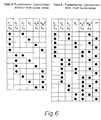
- Tables 1 and 2 of Fig. 6 contain three new parameters not found in the prior art: T r (reduced torque), P r (reduced power), and N e 2 (equivalent speed), each is divided by k s . Not only are T r and P r paired with N e 2, but all three are combined with one or two of the remaining coordinates (h r / k s , R c , q s 2/ k s , ⁇ ) to formulate a two-dimensional system for turbocompressors without guide vanes, or a three-dimensional system for units with guide vanes.
- the basic invariant coordinate systems are based on polytropic head, torque, and power as functions of flow, rotational speed, and inlet guide-vane position.
- Another coordinate system is presented using pressure ratio instead of polytropic head.
- power and torque are independent of head and pressure ratio
- combinations of power and head, power and pressure ratio, torque and head, or torque and pressure ratio can be used for control.
- the operating conditions that are used to calculate the distance from surge or stall are detected by process monitoring (measuring) devices located throughout the compressor-process system.
- Fig. 1 shows a surge protection system (with measuring devices) depicting a turbocompressor 101 pumping gas from a source 102 to an end user 106.
- Gas enters the compressor through an inlet line 103, into which is installed an orifice plate 104, and leaves by a discharge line 105.
- Flow is recycled to the source 102 via an antisurge valve 107.
- Fig. 1 also illustrates the antisurge control setup and its connections to the compression process.
- This arrangement includes a rotational speed transmitter 108, a guide vane position transmitter 109, an inlet pressure transmitter 110, a discharge pressure transmitter 111, an inlet temperature transmitter 112, a discharge temperature transmitter 113, a flow rate transmitter 114, (which measures differential pressure across the flow measuring device 104), an antisurge valve position transducer 115, a torque transmitter 116, a driver 117, and a power transmitter 118.
- Fig. 1 The monitoring equipment of Fig. 1 interacts with those computing modules shown in Fig. 2 and Fig. 3 which, in turn, display schematic diagram setups for turbocompressors without and with inlet guide vanes, respectively. Both assume constant k s .
- FIG. 2 illustrates an arrangement for turbocompressors without inlet guide vanes in (P r , R c ) coordinates.
- the equipment includes a module 119 which calculates pressure ratio, as the ratio of discharge pressure to suction pressure; while a module 120 determines reduced power at the surge limit (as a function of pressure ratio).
- Another module 121 calculates the ratio of power to rotational speed (rpm), the division of this ratio with suction pressure is computed as reduced power by a module 122.
- the relative slope is determined by a module 123, from the ratio of reduced power (at surge) to reduced power. The relative slope information then interacts with a control system to regulate turbocompressor flow rates.
- Figure 3 shows a computing-module arrangement for turbocompressors with inlet guide vanes in (P r , R c , ⁇ ) coordinates.
- the equipment includes a module 119 which calculates pressure ratio as the ratio of discharge pressure to suction; while a module 124 determines reduced power at the surge limit (as a function of pressure ratio and inlet guide vane angle).
- Another module 121 calculates the ratio of power to rotational speed (rpm), the division of this ratio with suction pressure is computed as reduced power by a module 122.
- the relative slope is determined by a module 123, from the ratio of reduced power (at surge) to reduced power.
- module 123 divides the values of reduced power (P r ) into the value of reduced power at surge (P r,surge ), to determine the relative slope (S rel ).
- P r,surge and f(R c ) are the same.
- S rel P r' surge P r f(R c ) P r which is the ratio of reduced power at surge to reduced power.
- the relative slope information then interacts with a control system to regulate turbocompressor flow rates.
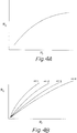
- Fig. 4A depicts a surge limit line plot for a turbocompressor without inlet guide vanes, in the fundamental coordinates (Table 1) shown on Fig. 2.
- Fig. 4B also depicts a surge limit line plot, but for a turbocompressor with inlet guide vanes, in the fundamental coordinates (Table 2) on Fig. 3.
- Fig. 5 shows a turbocompressor performance map which depicts characteristic curves along with the surge limit and control lines that define regions (zones) of operation.
- the fundamental coordinate systems are invariant to inlet conditions, and are founded on the theory of dimensional analysis or similitude. Except for inlet guide vane position, this invention focuses exclusively on fixed-geometry compressors.
- Tables 3 and 4 of Fig. 6 contain sets of fundamental coordinates for control with and without inlet guide vanes.
- the sets are combinations of the following:
- the compressor map in a coordinate system made up of nonlinear combinations of reduced polytropic head, reduced power, and reduced flow for control.
- the map may be constructed in the space: h r P r versus q r 2 P r
- This combination may be attractive because it is equivalent to h r / k 3 P r / k 3 versus q r 2 / k 3 P r / k 3 which is made up of parameters which are completely invariant to initial conditions--including the ratio of specific heats, k3.
- the advantage is that, using the form of Equation 1, k3 need not be known at all.
- the flow measurement has been referred to as located in suction. Flow measurement in discharge is also acceptable and may be substituted anywhere suction flow measurement appears.
Abstract
Description
- This invention relates to a method for protecting turbocompressors from adverse surges and stalls, specifically by utilizing sets of coordinates which are invariant to inlet conditions. And it is concerned with measuring distance from a turbocompressor's operating point to the Surge Limit Interface.
- Unstable or oscillatory flow conditions within a turbocompressor, known as surge and stall, are detrimental to process machinery and to the overall process operation. The proximity of the compressor to these unfavorable conditions is detected by process monitoring apparatuses that interact with control algorithms which regulate compressor flow rates within a stable operating region, thus avoiding surge and stall.
- Surge control is initiated by analog input signals emanating from various sources located throughout the compressor-process system. Although these signals are many, the set used must consist of relevant data to initiate control-algorithm response (by recirculating or blowing off some of the process gas) to any disturbance before the process flow rate reaches a surge condition.
- Prior art surge control can be divided into two categories: surge parameters which are invariant to inlet conditions, and those parameters which are not. Invariant parameters in the prior art consist of different combinations of reduced flow and pressure ratio; or combinations of volumetric flow divided by rotational speed, and polytropic head divided by rotational speed squared. The calculation of these parameters requires knowledge of at least the pressures at the suction and discharge of the turbocompressor, and a flow measurement (Δpo). One advantage of the present invention is that it is not limited to this combination of transmitter signals. Control strategies can be implemented using, for instance, a power measurement, suction pressure, and discharge pressure. Furthermore, the concept of this invention can be applied to the detection of fault and fallback strategies, which will keep the turbocompressors running under adverse circumstances.
- Of the second category of parameters (those not invariant), some are based on the same pressure and flow measurements as the first category, while others utilize a power or rotational speed measurement as a replacement for flow or discharge pressure measurement. Thus, a control scheme can be applied even if the turbocompressor lacks a flow or discharge pressure measurement. The advantage of the present invention over this prior art is that it does not require that corrections be made for changing inlet conditions.
- Thus, there is a need for a method of surge control that provides the flexibility of having a multiplicity of control strategies, together with fault checking and fallback. There is also a need for a surge control system, invariant to inlet conditions, that can accommodate compressor-process systems which are not fully instrumented or have faulty transmitters. A typical turbocompressor performance map (Fig. 5) will depict a surge region (zone) and a stable operating region that are separated by a sharp interface referred to as the Surge Limit Line. Also shown on this map is a Surge Control Line, and the distance between this line and the Surge Limit Line is a safety margin. If the operating point crosses the Surge Control Line, into the safety margin, the antisurge controller calculates a finite error; this error is used in the PI loop. The output of the loop is used to activate an electromechanical sequence in which gas is recycled or blown off to reestablish and maintain a safe flow rate. Should this safety margin be excessive, the frequency and duration of flow recycling will increase, resulting in a reduction of energy efficiency of the compression process. Conversely, should the margin be too brief, the prospect of inadequate protection is amplified.
- It is, therefore, obvious that considerable economic advantages can be derived from a narrow margin of safety that incorporates enhanced surge protection with a resultant lessening of process upset. Additional spin-off benefits would: better ensure efficient operation; extend the intervals between scheduled shutdowns; and increase annual monetary savings.
- For the foregoing reasons, there is a need to easily and accurately calculate (using invariant coordinate systems) at what point instability occurs under all inlet conditions.
- The present invention is directed to a method that satisfies the need to protect turbocompressors from detrimental surges and stalls by the use of various combinations of coordinate systems which are invariant to inlet conditions.
- To initiate surge detection and control, it is necessary to easily and accurately calculate a compressor's operating point and its distance from the interface (Surge Limit Interface) between the surge and stable regions using information from the transmitters at hand. Moreover, it is important to be able to calculate this relationship for all inlet conditions--pressure, temperature, molecular weight, compressibility, and specific heat ratio. To protect compressors under varying inlet conditions, one must either construct the Surge Limit Interface in a space which is invariant to these inlet conditions, or be able to correct for them.
- Using dimensional analysis, three-dimensional (without inlet guide vanes) and four-dimensional (with inlet guide vanes) coordinate systems are constructed which are invariant to inlet conditions, under the assumption that the Reynolds number is of negligible effect.
- The steady state operating point resides on a manifold which is one dimension less than the complete space in which it resides. Thus, for the purpose of control, the problem is reduced to two dimensions when inlet guide vanes are not used, and three dimensions when they are. These coordinate systems (fundamental coordinates), as shown below, yield several possibilities for control; however, linear or nonlinear combinations of the fundamental coordinates are also invariant and can be utilized.
- Tables 1 and 2 of Fig. 6 contain three new parameters not found in the prior art: Tr (reduced torque), Pr (reduced power), and Ne² (equivalent speed), each is divided by ks. Not only are Tr and Pr paired with
N e², but all three are combined with one or two of the remaining coordinates (hr / ks, Rc,q s²/ ks, α) to formulate a two-dimensional system for turbocompressors without guide vanes, or a three-dimensional system for units with guide vanes. - Since the ratio of specific heats (ks) is presently unmeasurable, it may be assumed to be constant in many instances, without loss of significant accuracy. It may also be calculated from known values when more accuracy is desired.
- From these tables of Fig. 6, the coordinate system that provides the most accurate control can be easily chosen. Furthermore, accurate control can be accomplished when the installation lacks certain transmitters such as flow measurement, temperatures, or downstream pressure. Besides providing flexibility for the primary control strategy of a given installation, the above mentioned alternatives provide avenues for fallback strategies in the event of transmitter failure and for fault tolerance.
- Additional advantages revealed are that no downstream information is required; accurate control or measurement is certain under varying inlet conditions; and any of the methods can be checked against other methods to improve control integrity.
- The basic invariant coordinate systems are based on polytropic head, torque, and power as functions of flow, rotational speed, and inlet guide-vane position. Another coordinate system is presented using pressure ratio instead of polytropic head.
- Since power and torque are independent of head and pressure ratio, combinations of power and head, power and pressure ratio, torque and head, or torque and pressure ratio, can be used for control.
- These and other features, aspects, and advantages of the present invention will become better understood with regard to the following description, appended claims, and accompanying drawings where:
- Fig. 1 shows a turbocompressor and its surge protection system (with measuring devices);
- Fig. 2 shows a schematic diagram of a computing-module setup for turbocompressors without inlet guide vanes;
- Fig. 3 shows a schematic diagram of a computing-module setup for turbocompressors with inlet guide vanes;
- Fig. 4A shows a surge limit line for a turbocompressor without inlet guide vanes in (Pr, Rc) coordinates;
- Fig. 4B shows a surge limit line for a turbocompressor with inlet guide vanes in (Pr, Rc, α) coordinates;
- Fig. 5 shows a turbocompressor performance map depicting the different operating regimes; and
- Fig. 6 shows two tables of fundamental coordinates: Table 1 shows viable combinations for turbocompressors without inlet guide vanes, and Table 2 for units with inlet guide vanes.
- To protect a turbocompressor from unstable or oscillatory flow conditions (surge or stall) it must be known at what point this instability occurs. There is an interface between a turbocompressor's stable operating region and the region in which it encounters surge or stall; and it is necessary to accurately calculate the operating point and its distance from this interface (Surge Limit Interface).
- The operating conditions that are used to calculate the distance from surge or stall are detected by process monitoring (measuring) devices located throughout the compressor-process system.
- Fig. 1 shows a surge protection system (with measuring devices) depicting a
turbocompressor 101 pumping gas from asource 102 to anend user 106. Gas enters the compressor through aninlet line 103, into which is installed anorifice plate 104, and leaves by adischarge line 105. Flow is recycled to thesource 102 via anantisurge valve 107. - Fig. 1 also illustrates the antisurge control setup and its connections to the compression process. This arrangement includes a
rotational speed transmitter 108, a guidevane position transmitter 109, aninlet pressure transmitter 110, adischarge pressure transmitter 111, aninlet temperature transmitter 112, adischarge temperature transmitter 113, aflow rate transmitter 114, (which measures differential pressure across the flow measuring device 104), an antisurgevalve position transducer 115, atorque transmitter 116, adriver 117, and apower transmitter 118. - The monitoring equipment of Fig. 1 interacts with those computing modules shown in Fig. 2 and Fig. 3 which, in turn, display schematic diagram setups for turbocompressors without and with inlet guide vanes, respectively. Both assume constant ks.
- Figure 2 illustrates an arrangement for turbocompressors without inlet guide vanes in (Pr , Rc) coordinates. The equipment includes a
module 119 which calculates pressure ratio, as the ratio of discharge pressure to suction pressure; while amodule 120 determines reduced power at the surge limit (as a function of pressure ratio). Anothermodule 121 calculates the ratio of power to rotational speed (rpm), the division of this ratio with suction pressure is computed as reduced power by amodule 122. And, finally, the relative slope is determined by amodule 123, from the ratio of reduced power (at surge) to reduced power. The relative slope information then interacts with a control system to regulate turbocompressor flow rates. Figure 3 shows a computing-module arrangement for turbocompressors with inlet guide vanes in (Pr, Rc, α) coordinates. The equipment includes amodule 119 which calculates pressure ratio as the ratio of discharge pressure to suction; while amodule 124 determines reduced power at the surge limit (as a function of pressure ratio and inlet guide vane angle). Anothermodule 121 calculates the ratio of power to rotational speed (rpm), the division of this ratio with suction pressure is computed as reduced power by amodule 122. And, lastly, the relative slope is determined by amodule 123, from the ratio of reduced power (at surge) to reduced power. This means thatmodule 123 divides the values of reduced power (Pr) into the value of reduced power at surge (Pr,surge), to determine the relative slope (Srel). Pr,surge and f(Rc) are the same.
which is the ratio of reduced power at surge to reduced power. The relative slope information then interacts with a control system to regulate turbocompressor flow rates. - Fig. 4A depicts a surge limit line plot for a turbocompressor without inlet guide vanes, in the fundamental coordinates (Table 1) shown on Fig. 2. Likewise, Fig. 4B also depicts a surge limit line plot, but for a turbocompressor with inlet guide vanes, in the fundamental coordinates (Table 2) on Fig. 3.
- Fig. 5 shows a turbocompressor performance map which depicts characteristic curves along with the surge limit and control lines that define regions (zones) of operation.
- The fundamental coordinate systems (see Fig. 6) are invariant to inlet conditions, and are founded on the theory of dimensional analysis or similitude. Except for inlet guide vane position, this invention focuses exclusively on fixed-geometry compressors.
- Tables 3 and 4 of Fig. 6 contain sets of fundamental coordinates for control with and without inlet guide vanes. The sets are combinations of the following:
- Tr
- = reduced torque
- hr
- = reduced polytropic head
- qs
- = reduced flow rate in suction
- Pr
- = reduced power
- Ne
- = equivalent speed
- Rc
- = pressure ratio
- α
- = inlet guide vane position
- ks
- = ratio of specific heats in suction
- T
- = torque
- σ
- = exponent:
- n
- = polytropic exponent
- k
- = ratio of specific heats
- pd
- = absolute pressure at discharge
- ps
- = absolute pressure in suction
- Δpo,s
- = flow measurement signal in suction
- P
- = power
- p
- = pressure
- N
- = rotational speed
- Z
- = compressibility
- R
- = gas constant:
- Ru
- = universal gas constant
- MW
- = molecular weight
- T
- = temperature
- s
- = subscript: suction
- r
- = reduced
- cp
- = specific heat at constant pressure
- cv
- = specific heat at constant volume
- Although the present invention has been described in detail, and with reference to several possibilities for control, linear or nonlinear combinations of these fundamental coordinates are also invariant and can be used.
- An infinite number of coordinate systems can be constructed based on the invariant coordinates presented in the previous sections. Many of these would be viable coordinates for control purposes. These combinations are considered part of the scope of this invention.
- By way of example, consider a compressor without inlet guide vanes. We can construct the compressor map in a coordinate system made up of nonlinear combinations of reduced polytropic head, reduced power, and reduced flow for control. In particular, the map may be constructed in the space:

This combination may be attractive because it is equivalent to
which is made up of parameters which are completely invariant to initial conditions--including the ratio of specific heats, k₃. The advantage is that, using the form ofEquation 1, k₃ need not be known at all. - The flow measurement has been referred to as located in suction. Flow measurement in discharge is also acceptable and may be substituted anywhere suction flow measurement appears.
- It is therefore to be understood that, within the scope of the appended claims, the invention may be practiced otherwise than as specifically described.
where;

and;
Claims (96)
- A method for measuring the distance of a tubocompressor's operation point to a Surge Limit Interface of said turbocompressor, said Surge Limit Interface comprising the locus of points separating the turbocompressor's stable operating region from its unstable region, said method comprising the steps of:(a) determining said Surge Limit Interface for the turbocompressor as a function of a parameter of the turbocompressor selected from reduced power, reduced torque and equivalent speed (PrKs; Tr/Ks; Ne²/Ks);(b) calculating a value that indicates the operating point of the turbocompressor as a function of the selected parameter;(c) comparing the operating point of the turbocompressor with the Surge Limit Interface; and(d) generating a signal corresponding to the position of the operating point of the turbocompressor relative to the surge point of the turbocompressor.
- A method for measuring the distance of a turbocompressor's operating point to a Surge Limit Interface of said turbocompressor, said Surge Limit Interface comprising the locus of points separating the turbocompressor's stable operating region from its unstable region, said method comprising the steps of:(a) determining said Surge Limit Interface for the turbocompressor as a function of a reduced power parameter, Pr / ks;(b) calculating a value that indicates the turbocompressor's operating point as a function of the reduced power parameter, Pr / ks; and(c) comparing the turbocompressor's operating point with said Surge Limit Interface and generating a signal corresponding to the position of the turbocompressor's operating point relative to the turbocompressor's surge point.
- The method of claim 1 or 2, wherein the step of comparing the turbocompressor's operating point with the Surge Limit Interface comprises the steps of:(a) calculating a setpoint at a predetermined position relative to the Surge Limit Interface; and(b) comparing the operating point with the setpoint.
- The method of any of the preceding claims, wherein the Surge Limit Interface is also determined as a function of one of the parameters which include reduced polytropic head (hr / ks), reduced flow rate (qs²/ ks), pressure ratio (Rc), inlet guide vane position (α), and equivalent speed (Ne²/ ks).
- The method of any of the preceding claims, wherein the Surge Limit Interface is also determined as a function of another one of the parameters which include reduced polytropic head (hr / ks), reduced flow rate (qs² / ks), pressure ratio (Rc), inlet guide vane position (α), and equivalent speed (Ne² / ks).
- The method of any of the preceding claims, wherein the step of calculating an operating point comprises the steps of:(a) sensing the power by a power measurement device and generating a power signal proportional to the power;(b) sensing the suction pressure of the turbocompressor by a pressure transmitter, and generating a suction pressure signal proportional to the suction pressure;(c) sensing the rotational speed by a speed measuring device and generating a speed signal proportional to the speed;(d) calculating Pr = P/ Nps from the power signal, suction pressure signal, and the speed signal;(e) calculating ks (ratio of specific heats) as a function of known values; and(f) calculating the operating point proportional to the reduced power parameter, Pr / ks.
- The method of any of the preceding claims, wherein the step of calculating a setpoint comprises the steps of:(a) plotting the Surge Limit Interface as a function of the reduced power parameter, Pr / ks, and one of the following: reduced polytropic head (hr / ks), reduced flow rate (qs²/ ks), pressure ratio (Rc), inlet guide vane position (α), and equivalent speed (Ne²/ ks);(b) selecting a setpoint reference line; and(c) setting the setpoint on the setpoint reference line at a predetermined position relative to the Surge Limit Interface.
- The method of claim 7, wherein the step of selecting a setpoint reference line comprises the steps of:(a) choosing a point on the Surge Limit Interface; and(b) selecting the line described by this point and the operating point.
- The method of any of the preceding claims, wherein the predetermined position of the setpoint, relative to the Surge Limit Interface, is adjustable during operation of the turbocompressor.
- A method for controlling a turbocompressor having a recycle line between its suction and discharge comprising the steps of:(a) determining a Surge Limit Interface for the turbocompressor as a function of a reduced power parameter, Pr / ks, said Surge Limit Interface comprising the locus of points separating the turbocompressor's stable operating region from its unstable region;(b) calculating the turbocompressor's operating point as a function of the reduced power parameter, Pr / ks;(c) comparing the turbocompressor's operating point with said Surge Limit Interface to determine the position of the turbocompressor's operating point relative to the turbocompressor's surge point;(d) generating a control signal corresponding to the position of the turbocompressor's operating point relative to the turbocompressor's surge point; and(e) modulating flow through the recycle line in response to the control signal so as to avoid surging of the turbocompressor.
- The method of claim 10, wherein the step of comparing the turbocompressor's operating point with the turbocompressor's surge point comprises the steps of:(a) calculating a setpoint at a predetermined position relative to the Surge Limit Interface; and(b) comparing the operating point with the setpoint.
- The method of claim 10 or 11, wherein the Surge Limit Interface is determined also as a function of another one of the following: reduced polytropic head (hr / ks), reduced flow rate (qs² / ks), pressure ratio (Rc), inlet guide vane position (α), and equivalent speed (Ne² / ks).
- The method of any of claims 10 to 12, wherein the step of calculating an operating point comprises the steps of:(a) sensing the power by a power measuring device and generating a power signal proportional to the power;(b) sensing the suction pressure of the turbocompressor by a pressure transmitter, and generating a suction pressure signal proportional to the suction pressure;(c) sensing the rotational speed by a speed measuring device and generating a speed signal proportional to the speed;(d) calculating ks as a function of known values;(e) calculating Pr = P/ Nps from the power signal, suction pressure signal, and the speed signal; and(f) calculating the operating point proportional to the reduced power parameter, Pr / ks.
- The method of claim 13, wherein the step of calculating a setpoint comprises the steps of:(a) plotting the Surge Limit Interface as a function of the reduced power parameter, Pr / ks, and another one of the following: reduced polytropic head (hr / ks), reduced flow rate (qs² / ks), pressure ratio (Rc), inlet guide vane position (α), and equivalent speed (Ne² / ks);(b) selecting a setpoint reference line; and(c) setting the setpoint on the setpoint reference line at a predetermined position relative to the Surge Limit Interface.
- The method of claim 14, wherein the step of selecting a setpoint reference line comprises the steps of:(a) choosing a point on the Surge limit Interface; and(b) selecting the line described by this point and the operating point.
- The method of claim 11, wherein the predetermined position of the setpoint relative to the Surge Limit Interface is adjustable during operation of the turbocompressor.
- A method for controlling a turbocompressor having a recycle line between its suction and discharge, comprising the steps of:(a) determining a Surge Limit Interface for the turbocompressor that is a function of the reduced power parameter, Pr / ks, and one or more of the following: reduced polytropic head (hr / ks), reduced flow rate (qs²/ ks), pressure ratio (Rc), inlet guide vane position (α), and equivalent speed (Ne² / ks), said Surge Limit Interface comprising the locus of points separating the turbocompressor's stable operating region from its unstable region;(b) sensing the power by a power measuring device and generating a power signal proportional to the power;(c) sensing the suction pressure of the turbocompressor and generating a suction pressure signal proportional to the suction pressure;(d) sensing the rotational speed by a speed measuring device and generating a speed signal proportional to the speed;(e) calculating Pr from the power signal, suction pressure signal, and the speed signal;(f) calculating ks as a function of known values;(g) calculating a value proportional to the reduced power parameter, Pr / ks;(h) calculating a value for a second parameter as a function of another one of hr / ks, qs²/ ks, Rc, α, or Ne²/ ks;(i) comparing the reduced power parameter, Pr / ks, and the second parameter with the Surge Limit Interface to generate a control signal corresponding to the position of the turbocompressor's operating point relative to the turbocompressor's surge point; and(j) modulating flow in the recycle line in response to the control signal so as to avoid surging of the turbocompressor.
- The method of claim 17, wherein determination of the Surge Limit Interface comprises the steps of:(a) calculating a value proportional to the reduced power parameter, Pr / ks;(b) calculating a value for a second parameter as a function of one of hr / ks, qs²/ ks, Rc, α, or Ne²/ ks;(c) calculating a value for a third parameter as a function of another one of hr/ks, qs²/ks, Rc, α or Ne²/ks; and(d) comparing the reduced power parameter, Pr / ks, and the second and third parameters with the Surge Limit Interface to generate a control signal corresponding to the position of the turbocompressor's operating point relative to the turbocompressor's surge point.
- The method of claim 17 or 18, wherein the step of comparing the reduced power parameter, Pr / ks, and the other parameters with the Surge Limit Interface comprises the steps of:(a) establishing a setpoint reference line;(b) selecting a setpoint on the setpoint reference line at a predetermined position relative to the Surge Limit Interface;(c) calculating a value representing the operating point to the turbocompressor along the setpoint reference line; and(d) comparing the operating point with the setpoint.
- The method of claim 19, wherein the step of selecting a setpoint reference line comprises the steps of:(a) choosing a point on the Surge Limit Interface; and(b) selecting the line described by this point and the operating point.
- The method of any of claims 17 to 20, wherein the step of calculating a value proportional to the reduced power parameter, Pr / ks, comprises the steps of:(a) dividing the rotational speed signal into the power signal to generate a P/ N value;(b) dividing P/ N by the suction pressure signal, ps, to generate a P/ Nps value which is proportional to Pr;(c) calculating ks from known values; and(d) dividing Pr by ks to generate a value which is proportional to the reduced power parameter, Pr / ks.
- The method of any of claims 17 to 21, wherein the step of comparing the reduced power parameter, Pr / ks, and said second parameter with the Surge Limit Interface comprises the steps of:(a) calculating a setpoint at a predetermined position relative to the Surge Limit Interface;(b) generating an operating point that is a function of the reduced power parameter, Pr / ks, and said second parameter; and(c) comparing the operating point with the setpoint.
- The method of claim 22, wherein the operating point is a function of the ratio of the reduced power parameter, Pr / ks, to the second parameter, multiplied by a function of a third parameter.
- The method of claim 23, wherein the operating point is the reduced power parameter, Pr / ks, divided by the second parameter, multiplied by a function of the third parameter (if existing) minus one, the second value modified to properly characterize the first signal in relation to the Surge Limit Interface.
- An apparatus for determining the position of a turbocompressor's operating point relative to the turbocompressor's surge point, comprising:(a) means for calculating a setpoint at a predetermined position relative to a Surge Limit Interface of the turbocompressor, that is a function of a reduced power parameter,
Pr / ks, said Surge Limit Interface comprising the locus of points separating the turbocompressor's stable operating region from its unstable region;(b) means for calculating an operating point as a function of the reduced power parameter, Pr / ks; and(c) means for comparing the operating point with the setpoint for generating a signal corresponding to the position of the turbocompressor's operating point relative to the turbocompressor's surge point. - The apparatus of claim 25, wherein the Surge Limit Interface is also a function of another one other parameters (hr / ks, qs²/ ks, Rc, α, or Ne²/ks).
- The apparatus of claim 25 or 26, wherein the means for calculating an operating point comprises:(a) means for sensing the power by a power measuring device and generating a power signal proportional to the power;(b) means for sensing pressure of the turbocompressor by a pressure transmitter, and generating a suction pressure signal proportional to the suction pressure;(c) means for sensing the rotational speed by a speed measuring device and generating a speed signal proportional to the speed;(d) means of calculating Pr from the power signal, pressure signal, and the speed signal;(e) means of calculating ks as a function of known values; and(f) means of calculating the operating point proportional to the reduced power parameter, Pr / ks.
- An apparatus for controlling a turbocompressor having a recycle line between its suction and discharge, comprising the steps:(a) means for calculating a setpoint at a predetermined position relative to the Surge Limit Interface of the turbocompressor that is a function of the reduced power parameter, Pr / ks, said Surge Limit Interface comprising the locus of points separating the turbocompressor's stable operating region from its unstable region;(b) means for calculating an operating point as a function of the reduced power parameter, Pr / ks;(c) means for comparing the turbocompressor's operating point with the Surge Limit Interface for determining the position of the turbocompressor's operating point relative to the turbocompressor's surge point;(d) means for generating a control signal corresponding to the position of the turbocompressor's operating point relative to the turbocompressor's surge point; and(e) means for modulating flow through the recycle line in response to the control signal so as to avoid surging of the turbocompressor.
- The apparatus of claim 28, wherein the Surge Limit Interface is also a function of another parameter (hr / ks, qs²/ ks, Rc, α, or Ne²/ ks).
- The apparatus of claim 28 or 29, wherein the means for calculating an operating point comprises:(a) means for sensing the power by a power measuring device and generating a power signal proportional to the power;(b) means for sensing suction pressure of the turbocompressor by a pressure transmitter and generating a suction pressure signal proportional to the suction pressure;(c) means for sensing the rotational speed by a speed measuring device and generating a speed signal proportional to the speed;(d) means for calculating Pr from the power signal, suction pressure signal, and the speed signal;(e) means for calculating ks as a function of known values; and(f) means for calculating the operating point proportional to the reduced power parameter, Pr / ks.
- An apparatus for controlling a turbocompressor having a recycle line between its suction and discharge, comprising:(a) means for calculating a setpoint at a predetermined position relative to the Surge Limit Interface for the turbocompressor, that is a function of the reduced power parameter, Pr / ks, and one more of the following: hr / ks, qs²/ ks, Rc, α, or Ne²/ ks, said Surge Limit Interface comprising the locus of points separating the turbocompressor's stable operating region from its unstable region;(b) means for sensing the power by a power measuring device and generating a power signal proportional to the power;(c) means for sensing the suction pressure of the turbocompressor by a pressure transmitter and generating a suction pressure signal proportional to the suction pressure;(d) means for sensing the rotational speed by a speed measuring device and generating a speed signal proportional to the speed;(e) means for calculating Pr from the power signal, suction pressure signal, and the speed signal;(f) means for calculating ks as a function of known values;(g) means for calculating a first value proportional to the reduced power parameter, Pr / ks;(h) means for calculating a value for a second parameter as a function of another one of hr / ks, qs²/ ks, Rc, α, Ne²/ ks;(i) means for comparing the first value and the second value with the setpoint signal, to generate a control signal corresponding to the position of the turbocompressor's operating point relative to the turbocompressor's surge point; and(j) means for modulating flow in the recycle line in response to the control signal so as to avoid surging of the turbocompressor.
- The apparatus corresponding to any of claims 17 to 31, wherein the means for calculating a set point comprises:(a) means for calculating a value proportional to the reduced power parameter, Pr / ks;(b) means for calculating a value for a second parameter as a function of one of hr / ks, qs²/ ks, Rc, α, or Ne²/ ks;(c) means for calculating a value for a third parameter as a function of another one of hr / ks, qs²/ ks, Rc, α, or Ne²/ ks; and(d) means for comparing the first value and the second and third values with the setpoint signal, to generate a control signal corresponding to the position of the turbocompressor's operating point relative to the turbocompressor's surge point.
- The apparatus of claim 31 or 32, wherein the means for calculating a first value proportional to the reduced power parameter, Pr / ks, comprises:(a) means for sensing the power by a power measuring device and generating a power signal proportional to the power;(b) means for sensing the suction pressure of the turbocompressor by a pressure transmitter, and generating a suction pressure signal proportional to the suction pressure;(c) means for sensing the rotational speed by a speed measuring device and generating a speed signal proportional to the speed;(d) means for calculating ks as a function of known values;(e) means for calculating Pr = P/Nps from the power signal, suction pressure signal, and the speed signal; and(f) means for generating the first value proportional to the reduced power parameter, Pr / ks.
- A method for measuring the distance of a turbocompressor's operating point to a Surge Limit Interface of said turbocompressor, said Surge Limit Interface comprising the locus of points separating the turbocompressor's stable operating region from its unstable region, said method[,] comprising the steps of:(a) determining said Surge Limit Interface for the turbocompressor as a function of a reduced torque parameter, Tr / ks;(b) calculating a value that indicates the turbocompressor's operating point as a function of the reduced torque parameter, Tr / ks; and(c) comparing the turbocompressor's operating point with said Surge Limit Interface and generating a signal corresponding to the position of the turbocompressor's operating point relative to the turbocompressor's surge point.
- The method of claim 34, wherein the step of comparing the turbocompressor's operating point with the Surge Limit Interface comprises the steps of:(a) calculating a setpoint at a predetermined position relative to the Surge Limit Interface; and(b) comparing the operating point with the setpoint.
- The method of claim 34 or 35, wherein the Surge Limit Interface is also determined as a function of one of the parameters which include reduced polytropic head (hr / ks), reduced flow rate (qs²/ ks), pressure ratio (Rc), inlet guide vane position (α), and equivalent speed (Ne²/ ks).
- The method of any of claims 34 to 36, wherein the Surge Limit Interface is also determined as a function of another one of the parameters which include reduced polytropic head (hr / ks), reduced flow rate (qs²/ks), pressure ratio (Rc), inlet guide vane position (α), and equivalent speed (Ne²/ks).
- The method of any of claims 34 to 37, wherein the step of calculating an operating point comprises the steps of:(a) sensing the torque by a torque measurement device and generating a torque signal proportional to the torque;(b) sensing the suction pressure of the turbocompressor by a pressure transmitter, and generating a suction pressure signal proportional to the suction pressure;(c) calculating Tr = T/ps from the torque signal and the suction pressure signal;(d) calculating ks (ratio of specific heats) as a function of known values; and(e) calculating the operating point proportional to the reduced torque parameter, Tr / ks.
- The method of any of claims 34 to 38, wherein the step of calculating a setpoint comprises the steps of:(a) plotting the Surge Limit Interface as a function of the reduced torque parameter, Tr / ks, and another one of the following: reduced polytropic head (hr / ks), reduced flow rate (qs²/ ks), pressure ratio (Rc), inlet guide vane position (α), and equivalent speed (Ne²/ ks);(b) selecting a setpoint reference line; and(c) setting the setpoint on the setpoint reference line at a predetermined position relative to the Surge Limit Interface.
- The method of claim 39, wherein the step of selecting a setpoint reference line comprises the steps of:(a) choosing a point on the Surge Limit Interface; and(b) selecting the line described by this point and the operating point.
- The method of any of claims 34 to 40, wherein the predetermined position of the setpoint, relative to the Surge Limit Interface, is adjustable during operation of the turbocompressor.
- A method for controlling a turbocompressor having a recycle line between its suction and discharge comprising the steps of:(a) determining a Surge Limit Interface for the turbocompressor as a function of a reduced torque parameter, Tr / ks, said Surge Limit Interface comprising the locus of points separating the turbocompressor's stable operating region from its unstable region;(b) calculating the turbocompressor's operating point as a function of the reduced torque parameter, Tr / ks;(c) comparing the turbocompressor's operating point with the Surge Limit Interface to determine the position of the turbocompressor's operating point relative to the turbocompressor's surge point;(d) generating a control signal corresponding to the position of the turbocompressor's operating point relative to the turbocompressor's surge point; and(e) modulating flow through the recycle line in response to the control signal so as to avoid surging the turbocompressor.
- The method of claim 42, wherein the step of comparing the turbocompressor's operating point with the turbocompressor's surge point comprises the steps of:(a) calculating a setpoint at a predetermined position relative to the Surge Limit Interface; and(b) comparing the operating point with the setpoint.
- The method of claim 42 or 43, wherein the Surge Limit Interface is determined also as a function of another one of the following: reduced polytropic head (hr / ks), reduced flow rate (qs²/ ks), pressure ratio (Rc), inlet guide vane position (α), and equivalent speed (Ne²/ ks).
- The method of any of claims 42 to 44, wherein the step of calculating an operating point comprises the steps of:(a) sensing the torque by a torque measuring device and generating a torque signal proportional to the torque;(b) sensing the suction pressure of the turbocompressor by a pressure transmitter, and generating a suction pressure signal proportional to the suction pressure;(c) calculating ks as a function of known values;(d) calculating Tr = T/ ps from the torque signal and the suction pressure signal; and(e) calculating the operating point proportional to the reduced torque parameter, Tr / ks.
- The method of any of claims 42 to 45, wherein the step of calculating a setpoint comprises the steps of:(a) plotting the Surge Limit Interface as a function of the reduced torque parameter, Tr / ks, and another one of the following: reduced polytropic head (hr / ks), reduced flow rate (qs²/ ks), pressure ratio (Rc), inlet guide vane position (α), and equivalent speed (Ne²/ ks);(b) selecting a setpoint reference line; and(c) setting the setpoint on the setpoint reference line at a predetermined position relative to the Surge Limit Interface.
- The method of claim 46, wherein the step of selecting a setpoint reference line comprises the steps of:(a) choosing a point on the Surge Limit Interface; and(b) selecting the line described by this point and the operating point.
- The method of any of claims 42 to 47, wherein the predetermined position of the setpoint relative to the Surge Limit Interface is adjustable during operation of the turbocompressor.
- A method for controlling a turbocompressor having a recycle line between its suction and discharge, comprising the steps of:(a) determining a Surge Limit Interface for the turbocompressor that is a function of the reduced torque parameter, Tr / ks, and one or more of the following: reduced polytropic head (hr / ks), reduced flow rate (qs²/ ks), pressure ratio (Rc), inlet guide vane position (α), and equivalent speed (Ne²/ ks), said Surge Limit Interface comprising the locus of points separating the turbocompressor's stable operating region from its unstable region;(b) sensing the torque by a torque measuring device and generating a torque signal proportional to the torque;(c) sensing the suction pressure of the turbocompressor and generating a suction pressure signal proportional to the suction pressure;(d) calculating Tr from the torque signal and the suction pressure signal;(e) calculating ks as a function of known values;(f) calculating a value proportional to the reduced torque parameter, Tr / ks;(g) calculating a value for a second parameter as a function of another one of hr / ks, qs²/ ks, Rc, α, or Ne²/ ks;(h) comparing the reduced torque parameter, Tr / ks, and the second parameter with the Surge Limit Interface to generate a control signal corresponding to the position of the turbocompressor's operating point relative to the turbocompressor's surge point; and(i) modulating flow in the recycle line in response to the control signal so as to avoid surging of the turbocompressor.
- The method of claim 49, wherein determination of the Surge Limit Interface comprises the steps of:(a) calculating a value proportional to the reduced torque parameter, Tr / ks;(b) calculating a value for a second parameter as a function of one of hr / ks, qs²/ ks, Rc, α, or Ne²/ ks;(c) calculating a value for a third parameter as a function of another one of hr / ks, qs²/ ks, Rc, α, or Ne²/ ks; and(d) comparing the reduced torque parameter, Tr / ks, and the second and third parameters with the Surge Limit Interface to generate a control signal corresponding to the position of the turbocompressor's operating point relative to the turbocompressor's surge point.
- The method of claim 49 or 50, wherein the step of comparing the reduced torque parameter, Tr / ks, and the other parameters with the Surge Limit Interface comprises the steps of:(a) establishing a setpoint reference line;(b) selecting a setpoint on the setpoint reference line at a predetermined position relative to the Surge Limit Interface;(c) calculating a value representing the operating point to the turbocompressor along the setpoint reference line; and(d) comparing the operating point with the setpoint.
- The method of any of claims 49 to 51, wherein the step of selecting a setpoint reference line comprises the steps of:(a) choosing a point on the Surge Limit Interface; and(b) selecting the line described by this point and the operating point.
- The method of any of claims 49 to 52, wherein the step of calculating a value proportional to the reduced torque parameter, Tr / ks, comprises the steps of:(a) dividing the suction pressure signal into the torque signal to generate a T/ps value which is proportional to Tr;(b) calculating ks from known values; and(c) dividing Tr by ks to generate a value which is proportional to the reduced torque parameter, Tr / ks.
- The method of any of claims 49 to 53, wherein the step of comparing the reduced torque parameter, Tr / ks, and the other parameters with the Surge Limit Interface comprises the steps of:(a) calculating a setpoint at a predetermined position relative to the Surge Limit Interface;(b) generating an operating point that is a function of the reduced torque parameter, Tr / ks, and the other parameters; and(c) comparing the operating point with the setpoint.
- The method of claim 54, wherein the operating point is a function of the ratio of the reduced torque parameter, Tr / ks, to the other parameters, multiplied by a function of the third parameter.
- The method of claim 54 wherein the operating point is the reduced torque parameter, Tr / ks, divided by the second parameter, multiplied by a function of the third parameter minus one, the second value modified to properly characterize the first signal in relation to the Surge Limit Interface.
- An apparatus for determining the position of a turbocompressor's operating point relative to the turbocompressor's surge point, comprising:(a) means for calculating a setpoint at a predetermined position relative to a Surge Limit Interface of the turbocompressor, that is a function of a reduced torque parameter, Tr / ks, said Surge Limit Interface comprising the locus of points separating the turbocompressor's stable operating region from its unstable region;(b) means for calculating an operating point as a function of the reduced torque parameter, Tr / ks; and(c) means for comparing the operating point with the setpoint for generating a signal corresponding to the position of the turbocompressor's operating point relative to the turbocompressor's surge point.
- The apparatus of claim 57, wherein the Surge Limit Interface is also a function of another one of (hr / ks, qs²/ ks, Rc, α, or Ne²/ ks).
- The apparatus of claim 57 or 58, wherein the means for calculating an operating point comprises:(a) means for sensing the torque by a torque measuring device and generating a torque signal proportional to the torque;(b) means for sensing pressure of the turbocompressor by a pressure transmitter, and generating a suction pressure signal proportional to the suction pressure;(c) means for calculating Tr from the torque signal and the suction pressure signal;(d) means for calculating ks as a function of known values; and(e) means for calculating the operating point proportional to the reduced torque parameter, Tr / ks.
- An apparatus for controlling a turbocompressor having a recycle line between its suction and discharge, comprising the steps:(a) means for calculating a setpoint at a predetermined position relative to the Surge Limit Interface of the turbocompressor that is a function of the reduced torque parameter, Tr / ks, said Surge Limit Interface comprising the locus of points separating the turbocompressor's stable operating region from its unstable region;(b) means for calculating an operating point as a function of the reduced torque parameter, Tr / ks;(c) means for comparing the turbocompressor's operating point with the Surge Limit Interface for determining the position of the turbocompressor's operating point relative to the turbocompressor's surge point;(d) means for generating a control signal corresponding to the position of the turbocompressor's operating point relative to the turbocompressor's surge point; and(e) means for modulating flow through the recycle line in response to the control signal so as to avoid surging the turbocompressor.
- The apparatus of claim 60, wherein the Surge Limit Interface is also a function of another parameter (hr/ ks, qs²/ ks, Rc, α, or Ne²/ks).
- The apparatus of claim 60 or 61, wherein the means for calculating an operating point comprises:(a) means for sensing the torque by a torque measuring device and generating a torque signal proportional to the torque;(b) means for sensing the suction pressure of the turbocompressor by a pressure transmitter and generating a suction pressure signal proportional to the suction pressure;(c) means for calculating Tr from the torque signal and the suction pressure signal;(d) means for calculating ks as a function of known values; and(e) means for calculating the operating point proportional to the reduced torque parameter, Tr / ks.
- An apparatus for controlling a turbocompressor having a recycle line between its suction and discharge, comprising:(a) means for calculating a setpoint at a predetermined position relative to the Surge Limit Interface for the turbocompressor, that is a function of the reduced torque parameter, Tr / ks, and one or more of the following parameters: hr / ks, qs²/ ks, Rc, α, or Ne²/ ks, said Surge Limit Interface comprising the locus of points separating the turbocompressor's stable operating region from its unstable region;(b) means for sensing the torque by a torque measuring device and generating a torque signal proportional to the torque;(c) means for sensing the suction pressure of the turbocompressor by a pressure transmitter and generating a suction pressure signal proportional to the suction pressure;(d) means for calculating Tr from the torque signal and suction pressure signal;(e) means for calculating ks as a function of known values;(f) means for calculating a first value proportional to the reduced torque parameter, Tr / ks;(g) means for calculating a value for a second parameter as a function of another one of hr / ks, qs²/ ks, Rc, α, Ne²/ ks;(h) means for comparing the first value and the second value with the setpoint signal, to generate a control signal corresponding to the position of the turbocompressor's operating point relative to the turbocompressor's surge point; and(i) means for modulating flow in the recycle line in response to the control signal so as to avoid surging of the turbocompressor.
- The apparatus of claim 63 wherein the means for calculating the setpoint comprises:(a) calculating a value proportional to the reduced torque parameter, Tr / ks;(b) calculating a value for a second parameter as a function of one of hr / ks, qs²/ ks, Rc, α, or Ne²/ ks;(c) calculating a value for a third parameter as a function of another one of hr / ks, qs²/ ks, Rc, α, or Ne²/ ks; and(d) a means for comparing the first value and the second and third values with the setpoint signal, to generate a control signal corresponding to the position of the turbocompressor's operating point relative to the turbocompressor's surge point.
- The apparatus of claim 63 or 64, wherein the means for calculating a first value proportional to the reduced torque parameter, Tr / ks, comprises:(a) means for sensing the torque by a torque measuring device and generating a torque signal proportional to the torque;(b) means for sensing the suction pressure of the turbocompressor by a pressure transmitter, and generating a suction pressure signal proportional to the suction pressure;(c) means for calculating ks as a function of known values;(d) means for calculating Tr = T/ ps from the torque signal and the suction pressure signal; and(e) means for generating the first value proportional to the reduced torque parameter, Tr / ks.
- A method for measuring the distance of a turbocompressor's operating point to a Surge Limit Interface of said turbocompressor, said Surge Limit Interface comprising the locus of points separating the turbocompressor's stable operating region from its unstable region, said method comprising the steps of:(a) determining said Surge Limit Interface for the turbocompressor as a function of an equivalent speed parameter, Ne² / ks;(b) calculating a value that indicates the turbocompressor's operating point as a function of the equivalent speed parameter, Ne²/ ks; and(c) comparing the turbocompressor's operating point with [the]said Surge Limit Interface and generating a signal corresponding to the position of the turbocompressor's operating point relative to the turbocompressor's surge point.
- The method of claim 66, wherein the step of comparing the turbocompressor's operating point with the Surge Limit Interface comprises the steps of:(a) calculating a setpoint at a predetermined position relative to the Surge Limit Interface; and(b) comparing the operating point with the setpoint.
- The method of claim 66 or 67, wherein the Surge Limit Interface is also determined as a function of one of several parameters which include reduced polytropic head (hr / ks), reduced flow rate (qs²/ ks), pressure ratio (Rc), inlet guide vane position (α), reduced power (Pr / ks), and reduced torque (Tr / ks).
- The method of any of claims 66 to 68, wherein the step of calculating an operating point comprises the steps of:(a) sensing the temperature by a temperature measurement device and generating a temperature signal proportional to the temperature;(b) sensing the rotational speed by a speed measuring device and generating a speed signal proportional to the speed;(c) squaring the speed signal;(d) dividing compressibility and the temperature signal into the square of the speed signal and multiplying by molecular weight to calculate a value proportional to Ne²;(e) calculating ks (ratio of specific heats) as a function of known values; and(f) calculating an operating point proportional to the equivalent speed parameter, Ne²/ ks.
- The method of any of claims 66 to 69, wherein the step of calculating a setpoint comprises the steps of:(a) plotting the Surge Limit Interface as a function of the equivalent speed parameter, Ne²/ ks, as a function of another one of the following: reduced polytropic head (hr / ks), reduced flow rate (qs²/ ks), pressure ratio (Rc), inlet guide vane position (α), reduced power (Pr / ks), and reduced torque (Tr / ks);(b) selecting a setpoint reference line; and(c) setting the setpoint on the setpoint reference line at a predetermined position relative to the Surge Limit Interface.
- The method of claim 70, wherein the step of selecting a setpoint reference line comprises the steps of:(a) choosing a point on the Surge Limit Interface; and(b) selecting the line described by this point and the operating point.
- The method of any of claims 66 to 71, wherein the predetermined position of the setpoint, relative to the Surge Limit Interface, is adjustable during operation of the turbocompressor.
- A method for controlling a turbocompressor having a recycle line between its suction and discharge comprising the steps of:(a) determining a Surge Limit Interface for the turbocompressor as a function of an equivalent speed parameter, Ne²/ ks, said Surge Limit Interface comprising the locus of points separating the turbocompressor's stable operating region from its unstable region;(b) calculating the turbocompressor's operating point as a function of the equivalent speed parameter, Ne²/ ks;(c) comparing the turbocompressor's operating point with the Surge Limit Interface to determine the position of the turbocompressor's operating point relative to the turbocompressor's surge point;(d) generating a control signal corresponding to the position of the turbocompressor's operating point relative to the turbocompressor's surge point; and(e) modulating flow through the recycle line in response to the control signal so as to avoid surging of the turbocompressor.
- The method of claim 73, wherein the step of comparing the turbocompressor's operating point with the turbocompressor's surge point comprises the steps of:(a) calculating a setpoint at a predetermined position relative to the Surge Limit Interface; and(b) comparing the operating point with the setpoint.
- The method of claim 73 or 74, wherein the Surge Limit Interface is determined also as a function of another one of the following: reduced polytropic head (hr / ks), reduced flow rate (qs²/ ks), pressure ratio (Rc), inlet guide vane position (α), reduced power (Pr / ks), and reduced torque (Tr / ks).
- The method of any of claims 73 to 75, wherein the step of calculating an operating point comprises the steps of:(a) sensing the temperature by a temperature measurement device and generating a temperature signal proportional to the temperature;(b) sensing the rotational speed by a speed measuring device and generating a speed signal proportional to the speed;(c) squaring the speed signal;(d) dividing compressibility and the temperature signal into the square of the speed signal and multiplying by molecular weight to calculate a value proportional to Ne²;(e) calculating ks as a function of known values; and(f) calculating an operating point proportional to the equivalent speed parameter, Ne²/ ks.
- The method of any of claims 73 to 76, wherein the step of calculating a setpoint comprises the steps of:(a) plotting the Surge Limit Interface as a function of the equivalent speed parameter, Ne²/ ks, as a function of another one of the following: reduced polytropic head (hr / ks), reduced flow rate (qs²/ ks), pressure ratio (Rc), inlet guide vane position (α), reduced power (Pr / ks), and reduced torque (Tr / ks);(b) selecting a setpoint reference line; and(c) setting the setpoint on the setpoint reference line at a predetermined position relative to the Surge Limit Interface.
- The method of claim 77, wherein the step of selecting a setpoint reference line comprises the steps of:(a) choosing a point on the Surge Limit Interface; and(b) selecting the line which is described by setting these parameters to these values.
- The method of any of claims 73 to 78, wherein the predetermined position of the setpoint relative to the Surge Limit Interface is adjustable during operation of the turbocompressor.
- A method for controlling a turbocompressor having a recycle line between its suction and discharge, comprising the steps of:(a) determining a Surge Limit Interface for the turbocompressor that is a function of the equivalent speed parameter, Ne²/ ks, and one or more of the following: reduced polytropic head (hr / ks), reduced flow rate (qs²/ ks), pressure ratio (Rc), inlet guide vane position (α), reduced power (Pr / ks), and reduced torque (Tr / ks), said Surge Limit Interface comprising the locus of points separating the turbocompressor's stable operating region from its unstable region;(b) sensing the temperature by a temperature measurement device and generating a temperature signal proportional to the temperature;(c) sensing the rotational speed by a speed measuring device and generating a speed signal proportional to the speed;(d) squaring the speed signal;(e) dividing compressibility and the temperature signal into the square of the speed signal and multiplying by molecular weight to calculate a value proportional to Ne²;(f) calculating ks as a function of known values;(g) calculating a value proportional to the equivalent speed parameter, Ne²/ ks;(h) calculating a value for a second parameter as a function of another one of hr / ks, qs²/ ks, Rc, α, Pr / ks, or Tr / ks;(i) comparing the equivalent speed parameter, Ne²/ ks, and the second parameter with the Surge Limit Interface to generate a control signal corresponding to the position of the turbocompressor's operating point relative to the turbocompressor's surge point; and(j) modulating flow in the recycle line in response to the control signal so as to avoid surging of the turbocompressor.
- The method of claim 80, wherein determination of the Surge Limit Interface comprises the steps of:(a) calculating a value proportional to the equivalent speed parameter, Ne²/ ks;(b) calculating a value for a second parameter as a function of one of hr / ks, qs²/ ks, Rc, α, Pr / ks, or Tr / ks;(c) calculating a value for a third parameter as a function of another one of hr / ks, qs²/ ks, Rc, α, Pr / ks, or Tr / ks; and(d) comparing the equivalent speed parameter, Ne²/ ks, and the second and third parameters with the Surge Limit Interface to generate a control signal corresponding to the position of the turbocompressor's operating point relative to the turbocompressor's surge point.
- The method of claim 80 or 81, wherein the step of comparing the equivalent speed parameter, Ne²/ ks, and the other parameters with the Surge Limit Interface comprises the steps of:(a) establishing a setpoint reference line;(b) selecting a setpoint on the setpoint reference line at a predetermined position relative to the Surge Limit Interface;(c) calculating a value representing the operating point to the turbocompressor along the setpoint reference line; and(d) comparing the operating point with the setpoint.
- The method of claim 82 wherein the step of selecting a setpoint reference line comprises the steps of:(a) choosing a point on the Surge Limit Interface; and(b) selecting the line described by this point and the operating point.
- The method of any of claims 80 to 83, wherein the step of calculating a value proportional to the equivalent speed parameter, Ne²/ ks, comprises the steps of:(a) squaring the speed signal;(b) dividing compressibility and the temperature signal into the square of the speed signal and multiplying by molecular weight to calculate a value proportional to Ne²;(c) calculating ks as a function of known values; and(d) dividing Ne² by ks to generate a value which is proportional to the equivalent speed parameter, Ne²/ ks.
- The method of any of claims 80 to 84, wherein the step of comparing the equivalent speed parameter, Ne²/ ks, and the other parameters with the Surge Limit Interface comprises the steps of:(a) calculating a setpoint at a predetermined position relative to the Surge Limit Interface;(b) generating an operating point that is a function of the equivalent speed parameter, Ne²/ ks, and the other parameters; and(c) comparing the operating point with the setpoint.
- The method of claim 85, wherein the operating point is a function of the ratio of the equivalent speed parameter, Ne²/ ks, to the second parameter, multiplied by a function of the third parameter.
- The method of claim 86, wherein the operating point is the equivalent speed parameter, Ne²/ ks, divided by the second parameter, multiplied by a function of the third parameter minus one, the first two values modified to properly characterize the first signal in relation to the Surge Limit Interface.
- An apparatus for determining the position of a turbocompressor's operating point relative to the turbocompressor's surge point, comprising:(a) means for calculating a setpoint at a predetermined position relative to a Surge Limit Interface of the turbocompressor, that is a function of an equivalent speed parameter, Ne²/ ks, said Surge Limit Interface comprising the locus of points separating the turbocompressor's stable operating region from its unstable region;(b) means for calculating an operating point as a function of the equivalent speed parameter, Ne²/ ks; and(c) a means for comparing the operating point with the setpoint for generating a signal corresponding to the position of the turbocompressor's operating point relative to the turbocompressor's surge point.
- The apparatus of claim 88, wherein the Surge Limit Interface is also a function of another one of hr / ks, qs²/ ks, Rc, α, Pr / ks, or Tr / ks.
- The apparatus of claim 88 or 89, wherein the means for calculating an operating point comprises:(a) means for sensing the temperature by a temperature measurement device and generating a temperature signal proportional to the temperature;(b) means for sensing the rotational speed by a speed measuring device and generating a speed signal proportional to the speed;(c) means for squaring the speed signal;(d) means for dividing compressibility and the temperature signal into the square of the speed signal and multiplying by molecular weight to calculate a value proportional to Ne²;(e) means of calculating ks as a function of known values; and(f) means of calculating the operating point proportional to the equivalent speed parameter, Ne²/ ks.
- An apparatus for controlling a turbocompressor having a recycle line between its suction and discharge, comprising the steps:(a) means for calculating a setpoint at a predetermined position relative to the Surge Limit Interface of the turbocompressor that is a function of the equivalent speed parameter, Ne²/ ks, said Surge Limit Interface comprising the locus of points separating the turbocompressor's stable operating region from its unstable region;(b) means for calculating an operating point as a function of the equivalent speed parameter, Ne²/ ks;(c) means for comparing the turbocompressor's operating point with the Surge Limit Interface for determining the position of the turbocompressor's operating point relative to the turbocompressor's surge point;(d) means for generating a control signal corresponding to the position of the turbocompressor's operating point relative to the turbocompressor's surge point; and(e) means for modulating flow through the recycle line in response to the control signal so as to avoid surging of the turbocompressor.
- The apparatus of claim 91, wherein the Surge Limit Interface is also a function of another parameter (hr / ks, qs²/ ks, Rc, α, Pr / ks, or Tr / ks.
- The apparatus of claim 91 or 92, wherein the means for calculating an operating point comprises:(a) means for sensing the temperature by a temperature measurement device and generating a temperature signal proportional to the temperature;(b) means for sensing the rotational speed by a speed measuring device and generating a speed signal proportional to the speed;(c) means for squaring the speed signal;(d) means for dividing compressibility and the temperature signal into the square of the speed signal and multiplying by molecular weight to calculate Ne²;(e) means for calculating ks as a function of known values; and(f) means for calculating the operating point proportional to the equivalent speed parameter, Ne²/ ks.
- An apparatus for controlling a turbocompressor having a recycle line between its suction and discharge, comprising:(a) means for calculating a setpoint at a predetermined position relative to the Surge Limit Interface for the turbocompressor, that is a function of the equivalent speed parameter, Ne²/ ks, and one or more of the following parameters: hr / ks, qs²/ ks, Rc, α, Pr / ks, or Tr / ks, said Surge Limit Interface comprising the locus of points separating the turbocompressor's stable operating region from its unstable region;(b) means for sensing the temperature by a temperature measurement device and generating a temperature signal proportional to the temperature;(c) means for sensing the rotational speed by a speed measuring device and generating a speed signal proportional to the speed;(d) means for squaring the speed signal;(e) means for dividing compressibility and the temperature signal into the square of the speed signal and multiplying by molecular weight to calculate Ne²;(f) means for calculating ks as a function of known values;(g) means for calculating a first value proportional to the equivalent speed parameter, Ne²/ ks;(h) means for calculating a value for a second parameter as a function of another one of hr / ks, qs²/ ks, Rc, α, Pr / ks, or Tr / ks;(i) means for comparing the first value and the second value with the setpoint signal, to generate a control signal corresponding to the position of the turbocompressor's operating point relative to the turbocompressor's surge point; and(j) means for modulating flow in the recycle line in response to the control signal so as to avoid surging the turbocompressor.
- The apparatus of claim 94, wherein said means for calculating the setpoint comprises:(a) means for calculating a value proportional to the equivalent speed parameter, Ne²/ ks;(b) means for calculating a value for a second parameter as a function of another one of hr / ks, qs²/ ks, Rc, α, Pr/ ks, or Tr/ ks;(c) means for calculating a value for a third parameter as a function of another one of hr / ks, qs²/ ks, Rc, α, Pr / ks, or Tr / ks; and(d) means for comparing the first value and the second and third values with the setpoint signal, to generate a control signal corresponding to the position of the turbocompressor's operating point relative to the turbocompressor's surge point.
- The apparatus of claim 94 or 95, wherein the means for calculating a first value proportional to the equivalent speed parameter, Ne²/ ks, comprises:(a) means for sensing the temperature by a temperature measurement device and generating a temperature signal proportional to the temperature;(b) means for sensing the rotational speed by a speed measuring device and generating a speed signal proportional to the speed;(c) means for squaring the speed signal;(d) means for dividing compressibility and the temperature signal into the square of the speed signal and multiplying by molecular weight to calculate Ne²;(e) means for calculating ks as a function of known values;(f) means for calculating Ne² = N²MW/ZRuT from the temperature signal, speed signal, compressibility and molecular weight; and(g) means for generating the first value proportional to the equivalent speed parameter, Ne²/ ks.
Applications Claiming Priority (2)
| Application Number | Priority Date | Filing Date | Title |
|---|---|---|---|
| US225448 | 1994-04-07 | ||
| US08/225,448 US5508943A (en) | 1994-04-07 | 1994-04-07 | Method and apparatus for measuring the distance of a turbocompressor's operating point to the surge limit interface |
Publications (2)
| Publication Number | Publication Date |
|---|---|
| EP0676545A2 true EP0676545A2 (en) | 1995-10-11 |
| EP0676545A3 EP0676545A3 (en) | 1997-07-02 |
Family
ID=22844909
Family Applications (1)
| Application Number | Title | Priority Date | Filing Date |
|---|---|---|---|
| EP95302259A Withdrawn EP0676545A3 (en) | 1994-04-07 | 1995-04-04 | Surge control method and apparatus. |
Country Status (5)
| Country | Link |
|---|---|
| US (1) | US5508943A (en) |
| EP (1) | EP0676545A3 (en) |
| CA (1) | CA2146583A1 (en) |
| NO (1) | NO951195L (en) |
| RU (1) | RU2168071C2 (en) |
Cited By (12)
| Publication number | Priority date | Publication date | Assignee | Title |
|---|---|---|---|---|
| EA000267B1 (en) * | 1995-10-20 | 1999-02-25 | Компрессор Контролз Корпорейшн | Method and apparatus for load balancing among multiple compressors |
| EP1031803A2 (en) * | 1999-02-26 | 2000-08-30 | Compressor Controls Corporation | Method and apparatus for maximizing the productivity of a natural gas liquids production plant |
| EP0967396A3 (en) * | 1998-06-26 | 2001-07-25 | MAN Turbomaschinen AG GHH BORSIG | Method for operation of turbo compressors |
| DE102004060206B3 (en) * | 2004-12-14 | 2006-06-14 | Siemens Ag | Method for operating a converter-fed compressor |
| EP1783048A2 (en) | 2005-11-08 | 2007-05-09 | Hamilton Sundstrand Corporation | Integral add heat and surge control valve for compressor |
| EP2042743A1 (en) * | 2007-09-27 | 2009-04-01 | ABB Research Ltd. | A gas compression system, a method for controlling a gas compression system, and a device for controlling a recycle valve |
| EP2386762A1 (en) * | 2010-05-11 | 2011-11-16 | Krishnan Narayanan | Method of anti-surge protection for a dynamic compressor using a surge parameter |
| WO2012013530A1 (en) * | 2010-07-29 | 2012-02-02 | Siemens Aktiengesellschaft | Method for operating a compressor |
| NO333438B1 (en) * | 2010-07-14 | 2013-06-03 | Statoil Asa | Method and apparatus for composition-based compressor control and performance monitoring. |
| EP2322877A3 (en) * | 2009-10-20 | 2015-05-27 | Johnson Controls Technology Company | Controllers and methods for providing computerized generation and use of a three dimensional surge map for control of chillers |
| WO2018007509A1 (en) * | 2016-07-07 | 2018-01-11 | Nuovo Pignone Tecnologie Srl | Compressor anti-surge protection under wet gas conditions |
| US10900492B2 (en) | 2010-05-11 | 2021-01-26 | Energy Control Technologies, Inc. | Method of anti-surge protection for a dynamic compressor using a surge parameter |
Families Citing this family (35)
| Publication number | Priority date | Publication date | Assignee | Title |
|---|---|---|---|---|
| CN1136485C (en) * | 1996-01-02 | 2004-01-28 | 伍德沃德调控器公司 | Surge prevention control system for dynamic compressors |
| US5743714A (en) * | 1996-04-03 | 1998-04-28 | Dmitry Drob | Method and apparatus for minimum work control optimization of multicompressor stations |
| KR20000015873A (en) * | 1996-05-22 | 2000-03-15 | 로날드 지. 헬러 | Method for detecting the occurrence of surge in a centrifugal compressor |
| US5832606A (en) * | 1996-09-17 | 1998-11-10 | Elliott Turbomachinery Co., Inc. | Method for preventing one-cell stall in bladed discs |
| US5908462A (en) * | 1996-12-06 | 1999-06-01 | Compressor Controls Corporation | Method and apparatus for antisurge control of turbocompressors having surge limit lines with small slopes |
| US6092029A (en) | 1998-02-19 | 2000-07-18 | Bently Nevada Corporation | Method and apparatus for diagnosing and controlling rotating stall and surge in rotating machinery |
| US6220086B1 (en) * | 1998-10-09 | 2001-04-24 | General Electric Co. | Method for ascertaining surge pressure ratio in compressors for turbines |
| US6317655B1 (en) * | 1999-02-12 | 2001-11-13 | Compressor Controls Corporation | Method and apparatus for estimating a surge limit line for configuring an antisurge controller |
| EP1069314A1 (en) * | 1999-07-16 | 2001-01-17 | Abb Research Ltd. | Control of a compressor unit |
| US6364602B1 (en) * | 2000-01-06 | 2002-04-02 | General Electric Company | Method of air-flow measurement and active operating limit line management for compressor surge avoidance |
| US6625573B2 (en) * | 2000-06-20 | 2003-09-23 | Petr A. Petrosov | Method and apparatus of molecular weight determination for gases flowing through the compressor |
| NO313926B1 (en) * | 2000-11-08 | 2002-12-23 | Abb Research Ltd | Compressor Controls |
| US6602057B2 (en) * | 2001-10-01 | 2003-08-05 | Dresser-Rand Company | Management and optimization of load sharing between multiple compressor trains for controlling a main process gas variable |
| US6920387B2 (en) * | 2001-12-06 | 2005-07-19 | Caterpillar Inc | Method and apparatus for parasitic load compensation |
| US6842689B2 (en) | 2002-05-15 | 2005-01-11 | Caterpillar Inc | System for dynamically controlling power provided by an engine |
| US7094019B1 (en) | 2004-05-17 | 2006-08-22 | Continuous Control Solutions, Inc. | System and method of surge limit control for turbo compressors |
| GB0716329D0 (en) * | 2007-08-21 | 2007-10-03 | Compair Uk Ltd | Improvements in compressors control |
| US7650218B2 (en) * | 2007-09-20 | 2010-01-19 | Cummins Ip, Inc | Apparatus, system, and method for preventing turbocharger overspeed in a combustion engine |
| US7757549B2 (en) * | 2008-02-21 | 2010-07-20 | Cummins Ip, Inc | Apparatus, system, and method for predictive control of a turbocharger |
| US7769522B2 (en) * | 2008-02-29 | 2010-08-03 | Cummins Ip, Inc | Apparatus and method for preventing an underspeed event of a turbocharger |
| DE102008058799B4 (en) * | 2008-11-24 | 2012-04-26 | Siemens Aktiengesellschaft | Method for operating a multi-stage compressor |
| EP2582984B1 (en) * | 2010-06-16 | 2016-04-27 | Sulzer Management AG | A turbomachine |
| RU2453734C1 (en) * | 2010-10-12 | 2012-06-20 | Закрытое акционерное общество "Научно-исследовательский и конструкторский институт центробежных и роторных компрессоров им. В.Б. Шнеппа" | Method of protecting radial-flow compressor against variable dynamic load |
| JP5276756B2 (en) * | 2011-03-31 | 2013-08-28 | 三菱重工業株式会社 | Operation method of gas compressor and gas turbine provided with gas compressor |
| US10436208B2 (en) * | 2011-06-27 | 2019-10-08 | Energy Control Technologies, Inc. | Surge estimator |
| US20130039781A1 (en) * | 2011-08-08 | 2013-02-14 | Victor Pascu | Anticipation logic for a surge control valve utilized with load compressor |
| ITCO20120056A1 (en) * | 2012-11-07 | 2014-05-08 | Nuovo Pignone Srl | METHOD OF OPERATING A COMPRESSOR IN CASE OF MALFUNCTION OF ONE OR MORE SIZES OF MEASUREMENT |
| KR101806920B1 (en) | 2013-04-19 | 2018-01-10 | 한화파워시스템 주식회사 | Compressor system and controlling method of the same |
| NO338575B1 (en) * | 2014-09-16 | 2016-09-05 | Fmc Kongsberg Subsea As | System for pumping a fluid and process for its operation. |
| US9506474B2 (en) * | 2014-12-08 | 2016-11-29 | Ford Global Technologies, Llc | Methods and systems for real-time compressor surge line adaptation |
| NO338836B1 (en) * | 2015-06-11 | 2016-10-24 | Fmc Kongsberg Subsea As | Load-sharing in parallel fluid pumps |
| US10254719B2 (en) | 2015-09-18 | 2019-04-09 | Statistics & Control, Inc. | Method and apparatus for surge prevention control of multistage compressor having one surge valve and at least one flow measuring device |
| IT201600070842A1 (en) | 2016-07-07 | 2018-01-07 | Nuovo Pignone Tecnologie Srl | METHOD AND ADAPTIVE ANTI-PUMP CONTROL SYSTEM |
| US20180163736A1 (en) * | 2016-12-09 | 2018-06-14 | General Electric Company | Systems and methods for operating a compression system |
| BE1027043B1 (en) | 2019-02-08 | 2020-09-08 | Safran Aero Boosters Sa | TOTAL PRESSURE AND TOTAL TEMPERATURE MEASUREMENT IN A TURBOMACHINE |
Citations (4)
| Publication number | Priority date | Publication date | Assignee | Title |
|---|---|---|---|---|
| US3876326A (en) * | 1974-01-30 | 1975-04-08 | Simmonds Precision Products | Surge control system |
| US4686834A (en) * | 1986-06-09 | 1987-08-18 | American Standard Inc. | Centrifugal compressor controller for minimizing power consumption while avoiding surge |
| EP0366219A2 (en) * | 1988-10-26 | 1990-05-02 | Compressor Controls Corporation | Method and apparatus for preventing surge in a dynamic compressor |
| US5046928A (en) * | 1989-12-26 | 1991-09-10 | Westingshouse Electric Corp. | Long term compressor control apparatus |
Family Cites Families (6)
| Publication number | Priority date | Publication date | Assignee | Title |
|---|---|---|---|---|
| US4156578A (en) * | 1977-08-02 | 1979-05-29 | Agar Instrumentation Incorporated | Control of centrifugal compressors |
| DE3544821A1 (en) * | 1985-12-18 | 1987-06-19 | Gutehoffnungshuette Man | METHOD FOR REGULATING TURBO COMPRESSORS TO AVOID THE PUMP |
| DE3544822A1 (en) * | 1985-12-18 | 1987-06-19 | Gutehoffnungshuette Man | METHOD FOR CONTROLLING PUMP LIMITS OF TURBO COMPRESSORS |
| DE3805119A1 (en) * | 1988-02-18 | 1989-08-31 | Gutehoffnungshuette Man | METHOD AND DEVICE FOR REGULATING TURBO COMPRESSORS |
| US4971516A (en) * | 1988-05-04 | 1990-11-20 | Exxon Research & Engineering Company | Surge control in compressors |
| US5306116A (en) * | 1992-04-10 | 1994-04-26 | Ingersoll-Rand Company | Surge control and recovery for a centrifugal compressor |
-
1994
- 1994-04-07 US US08/225,448 patent/US5508943A/en not_active Expired - Lifetime
-
1995
- 1995-03-29 NO NO951195A patent/NO951195L/en unknown
- 1995-04-04 EP EP95302259A patent/EP0676545A3/en not_active Withdrawn
- 1995-04-07 CA CA002146583A patent/CA2146583A1/en not_active Abandoned
- 1995-04-07 RU RU95105593/06A patent/RU2168071C2/en not_active IP Right Cessation
Patent Citations (5)
| Publication number | Priority date | Publication date | Assignee | Title |
|---|---|---|---|---|
| US3876326A (en) * | 1974-01-30 | 1975-04-08 | Simmonds Precision Products | Surge control system |
| US4686834A (en) * | 1986-06-09 | 1987-08-18 | American Standard Inc. | Centrifugal compressor controller for minimizing power consumption while avoiding surge |
| EP0366219A2 (en) * | 1988-10-26 | 1990-05-02 | Compressor Controls Corporation | Method and apparatus for preventing surge in a dynamic compressor |
| EP0500196A2 (en) * | 1988-10-26 | 1992-08-26 | Compressor Controls Corporation | Method and apparatus for preventing surge in a dynamic compressor |
| US5046928A (en) * | 1989-12-26 | 1991-09-10 | Westingshouse Electric Corp. | Long term compressor control apparatus |
Non-Patent Citations (1)
| Title |
|---|
| ADVANCES IN INSTRUMENTATION, vol. 31, no. 1, 1976, pages 1 -15, XP002030689 J. D. WARNOCK: "Typical Compressor Control Configurations" * |
Cited By (21)
| Publication number | Priority date | Publication date | Assignee | Title |
|---|---|---|---|---|
| EA000267B1 (en) * | 1995-10-20 | 1999-02-25 | Компрессор Контролз Корпорейшн | Method and apparatus for load balancing among multiple compressors |
| EP0967396A3 (en) * | 1998-06-26 | 2001-07-25 | MAN Turbomaschinen AG GHH BORSIG | Method for operation of turbo compressors |
| EP1031803A2 (en) * | 1999-02-26 | 2000-08-30 | Compressor Controls Corporation | Method and apparatus for maximizing the productivity of a natural gas liquids production plant |
| EP1031803A3 (en) * | 1999-02-26 | 2001-10-10 | Compressor Controls Corporation | Method and apparatus for maximizing the productivity of a natural gas liquids production plant |
| DE102004060206B3 (en) * | 2004-12-14 | 2006-06-14 | Siemens Ag | Method for operating a converter-fed compressor |
| EP1825147B1 (en) * | 2004-12-14 | 2011-02-09 | Siemens Aktiengesellschaft | Method for operation of a compressor supplied by a power converter |
| US8070456B2 (en) | 2004-12-14 | 2011-12-06 | Siemens Aktiengesellschaft | Method for preventing power surge in a compressor supplied by a power converter by direct torque control |
| EP1783048A2 (en) | 2005-11-08 | 2007-05-09 | Hamilton Sundstrand Corporation | Integral add heat and surge control valve for compressor |
| EP1783048A3 (en) * | 2005-11-08 | 2009-08-19 | Hamilton Sundstrand Corporation | Integral add heat and surge control valve for compressor |
| EP2377759A1 (en) * | 2005-11-08 | 2011-10-19 | Hamilton Sundstrand Corporation | Integral add heat and surge control valve for compressor |
| EP2042743A1 (en) * | 2007-09-27 | 2009-04-01 | ABB Research Ltd. | A gas compression system, a method for controlling a gas compression system, and a device for controlling a recycle valve |
| EP2322877A3 (en) * | 2009-10-20 | 2015-05-27 | Johnson Controls Technology Company | Controllers and methods for providing computerized generation and use of a three dimensional surge map for control of chillers |
| EP2386762A1 (en) * | 2010-05-11 | 2011-11-16 | Krishnan Narayanan | Method of anti-surge protection for a dynamic compressor using a surge parameter |
| US10900492B2 (en) | 2010-05-11 | 2021-01-26 | Energy Control Technologies, Inc. | Method of anti-surge protection for a dynamic compressor using a surge parameter |
| NO333438B1 (en) * | 2010-07-14 | 2013-06-03 | Statoil Asa | Method and apparatus for composition-based compressor control and performance monitoring. |
| US9416790B2 (en) | 2010-07-14 | 2016-08-16 | Statoil Asa | Method and apparatus for composition based compressor control and performance monitoring |
| CN103038516A (en) * | 2010-07-29 | 2013-04-10 | 西门子公司 | Method for operating a compressor |
| CN103038516B (en) * | 2010-07-29 | 2015-04-01 | 西门子公司 | Method for operating a compressor |
| WO2012013530A1 (en) * | 2010-07-29 | 2012-02-02 | Siemens Aktiengesellschaft | Method for operating a compressor |
| US9410551B2 (en) | 2010-07-29 | 2016-08-09 | Siemens Aktiengesellschaft | Method for operating a compressor |
| WO2018007509A1 (en) * | 2016-07-07 | 2018-01-11 | Nuovo Pignone Tecnologie Srl | Compressor anti-surge protection under wet gas conditions |
Also Published As
| Publication number | Publication date |
|---|---|
| NO951195D0 (en) | 1995-03-29 |
| RU2168071C2 (en) | 2001-05-27 |
| EP0676545A3 (en) | 1997-07-02 |
| RU95105593A (en) | 1997-01-10 |
| NO951195L (en) | 1995-10-09 |
| CA2146583A1 (en) | 1995-10-08 |
| US5508943A (en) | 1996-04-16 |
Similar Documents
| Publication | Publication Date | Title |
|---|---|---|
| US5508943A (en) | Method and apparatus for measuring the distance of a turbocompressor's operating point to the surge limit interface | |
| US5947680A (en) | Turbomachinery with variable-angle fluid guiding vanes | |
| Fink et al. | Surge dynamics in a free-spool centrifugal compressor system | |
| US5195875A (en) | Antisurge control system for compressors | |
| US8152496B2 (en) | Continuing compressor operation through redundant algorithms | |
| US4526513A (en) | Method and apparatus for control of pipeline compressors | |
| US7094019B1 (en) | System and method of surge limit control for turbo compressors | |
| CN106050722B (en) | Complete performance surge controlling method and system based on the principle of similitude | |
| EP2331825B1 (en) | Method of controlling a compressor and apparatus therefor | |
| US4831535A (en) | Method of controlling the surge limit of turbocompressors | |
| EP0769624A1 (en) | Method and apparatus for load balancing among multiple compressors | |
| US5908462A (en) | Method and apparatus for antisurge control of turbocompressors having surge limit lines with small slopes | |
| US5599161A (en) | Method and apparatus for antisurge control of multistage compressors with sidestreams | |
| US10254719B2 (en) | Method and apparatus for surge prevention control of multistage compressor having one surge valve and at least one flow measuring device | |
| EP1031803B1 (en) | Method and apparatus for maximizing the productivity of a natural gas liquids production plant | |
| US9410551B2 (en) | Method for operating a compressor | |
| EP3406908A1 (en) | Method of anti-surge protection for a dynamic compressor using a surge parameter | |
| JPH01300093A (en) | Surge avoiding method of turbo compressor by adjusting blow-off | |
| US10900492B2 (en) | Method of anti-surge protection for a dynamic compressor using a surge parameter | |
| WO2009041851A1 (en) | Method for monitoring the operating modes of a compressor and a device for carrying out said method | |
| RU2458257C1 (en) | Protection method for turbocompressor against stalling | |
| Graf et al. | Effects of non-axisymmetric tip clearance on axial compressor performance and stability | |
| US6494672B1 (en) | Method and apparatus for antisurge control of turbocompressors having complex and changing surge limit lines | |
| US5699267A (en) | Hot gas expander power recovery and control | |
| Summers | Developing centrifugal compressor train optimization models for performance evaluation |
Legal Events
| Date | Code | Title | Description |
|---|---|---|---|
| PUAI | Public reference made under article 153(3) epc to a published international application that has entered the european phase |
Free format text: ORIGINAL CODE: 0009012 |
|
| AK | Designated contracting states |
Kind code of ref document: A2 Designated state(s): AT BE CH DE DK ES FR GB GR IE IT LI LU MC NL PT SE |
|
| PUAL | Search report despatched |
Free format text: ORIGINAL CODE: 0009013 |
|
| AK | Designated contracting states |
Kind code of ref document: A3 Designated state(s): AT BE CH DE DK ES FR GB GR IE IT LI LU MC NL PT SE |
|
| 17P | Request for examination filed |
Effective date: 19970725 |
|
| 17Q | First examination report despatched |
Effective date: 20010313 |
|
| RTI1 | Title (correction) |
Free format text: SURGE CONTROL METHOD |
|
| GRAH | Despatch of communication of intention to grant a patent |
Free format text: ORIGINAL CODE: EPIDOS IGRA |
|
| RTI1 | Title (correction) |
Free format text: SURGE CONTROL METHOD |
|
| STAA | Information on the status of an ep patent application or granted ep patent |
Free format text: STATUS: THE APPLICATION IS DEEMED TO BE WITHDRAWN |
|
| 18D | Application deemed to be withdrawn |
Effective date: 20031216 |