EP0674594B1 - Automotive seat switch assembly - Google Patents
Automotive seat switch assembly Download PDFInfo
- Publication number
- EP0674594B1 EP0674594B1 EP94904467A EP94904467A EP0674594B1 EP 0674594 B1 EP0674594 B1 EP 0674594B1 EP 94904467 A EP94904467 A EP 94904467A EP 94904467 A EP94904467 A EP 94904467A EP 0674594 B1 EP0674594 B1 EP 0674594B1
- Authority
- EP
- European Patent Office
- Prior art keywords
- switch
- assembly
- support posts
- rail member
- contactor
- Prior art date
- Legal status (The legal status is an assumption and is not a legal conclusion. Google has not performed a legal analysis and makes no representation as to the accuracy of the status listed.)
- Expired - Lifetime
Links
Images


Classifications
-
- B—PERFORMING OPERATIONS; TRANSPORTING
- B60—VEHICLES IN GENERAL
- B60N—SEATS SPECIALLY ADAPTED FOR VEHICLES; VEHICLE PASSENGER ACCOMMODATION NOT OTHERWISE PROVIDED FOR
- B60N2/00—Seats specially adapted for vehicles; Arrangement or mounting of seats in vehicles
- B60N2/02—Seats specially adapted for vehicles; Arrangement or mounting of seats in vehicles the seat or part thereof being movable, e.g. adjustable
- B60N2/0224—Non-manual adjustments, e.g. with electrical operation
- B60N2/0226—User interfaces specially adapted for seat adjustment
- B60N2/0228—Hand-activated mechanical switches
-
- B—PERFORMING OPERATIONS; TRANSPORTING
- B60—VEHICLES IN GENERAL
- B60N—SEATS SPECIALLY ADAPTED FOR VEHICLES; VEHICLE PASSENGER ACCOMMODATION NOT OTHERWISE PROVIDED FOR
- B60N2/00—Seats specially adapted for vehicles; Arrangement or mounting of seats in vehicles
- B60N2/02—Seats specially adapted for vehicles; Arrangement or mounting of seats in vehicles the seat or part thereof being movable, e.g. adjustable
- B60N2/0224—Non-manual adjustments, e.g. with electrical operation
- B60N2/0226—User interfaces specially adapted for seat adjustment
- B60N2/0229—User interfaces specially adapted for seat adjustment characterised by the shape, e.g. switches having cushion or backrest shape
-
- H—ELECTRICITY
- H01—ELECTRIC ELEMENTS
- H01H—ELECTRIC SWITCHES; RELAYS; SELECTORS; EMERGENCY PROTECTIVE DEVICES
- H01H15/00—Switches having rectilinearly-movable operating part or parts adapted for actuation in opposite directions, e.g. slide switch
- H01H15/02—Details
- H01H15/06—Movable parts; Contacts mounted thereon
- H01H15/10—Operating parts
- H01H15/102—Operating parts comprising cam devices
-
- H—ELECTRICITY
- H01—ELECTRIC ELEMENTS
- H01H—ELECTRIC SWITCHES; RELAYS; SELECTORS; EMERGENCY PROTECTIVE DEVICES
- H01H2217/00—Facilitation of operation; Human engineering
- H01H2217/04—Mimics of controlled apparatus or symbol
-
- H—ELECTRICITY
- H01—ELECTRIC ELEMENTS
- H01H—ELECTRIC SWITCHES; RELAYS; SELECTORS; EMERGENCY PROTECTIVE DEVICES
- H01H2300/00—Orthogonal indexing scheme relating to electric switches, relays, selectors or emergency protective devices covered by H01H
- H01H2300/008—Application power seats
Definitions
- This invention relates to automotive switch assemblies and more particularly to a seat switch for controlling the electric motors which adjust seat position in vehicle interiors.
- fractional horsepower DC electric motors are utilized to achieve seat position adjustment in vehicle interiors.
- four degrees of seat adjustment are provided, namely (1) forward-aft seat position, (2) vertical height of the forward portion of the seat bench, (3) vertical height of the rearward portion of the seat bench, and (4) angular position (i.e., tilt) of the seat back.
- a known seat switch design utilizes two knobs which control four switch actuators in the switch assembly.
- the knobs are formed in the general shape of a seat back and a seat bench for ease of use in operating the switch.
- the seat back shaped knob controls one switch actuator and the seat bench shaped knob controls three switch actuators for the desired four degrees of adjustment.
- the seat switch has a subassembly of conductive strips or bus bars which are selectively interconnected by the switch actuators to provide power to the respective positioning motors.
- the buses are connected to a wire assembly having a terminal which connects to a wire harness in the vehicle to interconnect the seat switch to the positioning motors.
- the subassembly of buses has heretofore been fabricated of layers of conductors separated by insulating sheets mounted together within the switch housing prior to assembly of the switch actuators.
- the multilayer construction and fabrication of the buses and separating sheets required a large size switch housing. It is desirable to reduce the size of the switch housing, particularly the thickness of the switch assembly as such switches are often mounted in a door panel. Partly due to the size of the switch assembly, attachment of the switch assembly to the vehicle was accomplished by fasteners such as screws. Accordingly, it would be desirable to achieve secure fastenerless attachment to a vehicle in a manner which facilitates vehicle assembly.
- DE-C-3 904 771 (C1) describes an automotive switch assembly, namely an automobile seat switch assembly for controlling seat movement, comprising a switch housing having a front cover, a middle switch plate, namely a printed circuit board into which switch modules are soldered, and a back cover.
- a further object of the invention is to provide a seat switch assembly which facilitates manufacture and installation with enhanced reliability of operation.
- a further object of the invention is to provide a seat switch assembly which achieves fastenerless mounting to a vehicle.
- a still further object of the invention is to provide an automotive switch of the slide actuator type which facilitates manufacture and enhances reliability.
- a further object of the invention is to provide an automotive switch which affords outline design illumination of the switch.
- the invention provides an automotive switch assembly as set out in claim 1.
- the invention also provides an automobile seat switch assembly as set out in claim 2.
- a preferred seat switch assembly in accordance with the invention in which disadvantages of the prior art are overcome comprises a housing comprising a front cover, a middle switch plate and a back cover.
- the switch plate is an insert molded unitary switch plate with a plurality of electrical buses molded therein and an upper support surface with a plurality of contact surfaces.
- a plurality of switch actuator assemblies are mounted on the support surface.
- Each switch actuator assembly has a contactor for electrically contacting a respective contact surface, a contactor actuator slidably mounted to a rail member for sliding movement to actuate the contactor and a pair of space support posts extending from the support surface.
- the rail member and the support posts are configured for interlocking snap lock engagement to secure the rail member to the support posts.
- the front cover is mounted to the switch plate to enclose the switch actuator assemblies.
- Switch knobs connected to the contactor actuators are mounted at the exterior wall of the front cover.
- the exterior wall has a translucent section which defines an outline design such as the outline of an automobile seat about the knobs.
- An optical fiber is configured in the form of the outline design and is mounted within the switch housing adjacent the translucent section. The opposite ends of the optical fiber terminate at a light source within the switch housing to illuminate the optical fiber and thus the outline design about the knobs.
- the housing includes fastenerless snap lock mounting tabs for snap lock mounting to a support structure within the vehicle interior.
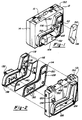
- Figure 1 is a partly broken away perspective view of the preferred seat switch assembly embodying the present invention.
- Figure 2 is an exploded perspective view of the front cover of the switch assembly of Figure 1.
- Figure 3 is a plan view of the switch plate.
- Figure 4 is an enlarged broken away perspective view of a switch actuator assembly.
- Figure 5 is an exploded perspective view of the assembly of Figure 4.
- Figure 6 is an elevational view partly in section of the actuator assembly of Figure 4.
- a switch housing is generally formed by an interlocking front cover assembly 12, middle switch plate 14 and back cover 16.
- the switch plate 14 (Fig. 3) is an insert molded unitary plate member with a plurality of bus bars or conductors 18 molded therein.
- the terminal end of each bus bar has an aperture 20 for connecting the bus bar to a wire assembly (not shown) by a rivet or the like.
- the wire assembly connects the seat switch to a vehicle wire harness to thereby electrically connect the switch to the seat positioning motors.
- Insert molding is a known procedure for fabricating bus bars in an electrically insulating plate and need not be described in detail for purposes of the present invention.
- the switch actuator assembly 24 generally comprises a contactor 26, a contactor actuator 28 and a rail member or pin 30.
- the contactor 26 is mounted to a yoke or bracket 32 for pivotal movement between a closed position wherein one end 34 engages the contact point or surface 36 on upper surface 22 to make an electrical connection and an open position wherein the end 34 is disengaged from the contact surface 36 and the other end 38 of contactor 26 engages the stop 40.
- the contactor 26 is formed of electrically conducting material such as copper as is the support bracket 32.
- the support bracket 32 and the contact surface 36 are insert molded in plate 14.
- the support bracket 32 is electrically connected to one of the bus bars 18 to connect the bus bar to the contactor.
- the contact surface 36 is electrically connected to another bus bar 18 such as a common ground bus bar so that when the contactor 26 is in a closed position, the bus bar connected to bracket 32 is electrically connected to ground to complete a circuit and provide power to one of the seat motors.
- the contactor actuator 28 is slidably mounted to the rail or pin 30 for sliding movement to actuate the contactor 26 between the open and closed positions.
- the pin 30 has a cylindrical shank 42 and a flat annular head 44.
- the contactor actuator 28 has a through bore 46 to receive the shank 42 for sliding movement of the actuator 28 along the pin 30.
- the actuator 28 includes a plunger 48 spring biased against the contactor 26 by the coil spring 50. As the actuator 28 is moved from left to right as viewed in Figure 6, the contactor 26 will be pivoted clockwise from the closed position (as shown) to an open position (whereby the end 34 is raised from and electrically disconnected from contact surface 36).
- a stop 52, bracket 54 and contact surface 56 are positioned adjacent contact surface 36, bracket 32 and stop 40, respectively for a second contactor (not shown).
- the second contactor is mounted to bracket 54 and engaged by a second plunger 58 of actuator 28.
- the contactor 28 also has a pair of apertures 60 to receive knob stems 62 to connect the actuator to a knob for manually sliding the contactor actuator.
- Pin 30 is mounted to a pair of integrally molded support posts 64, 66 which extend upwardly from the support surface 22.
- the posts 64, 66 and pin 30 are configured for interlocking engagement to secure the pin to the posts.
- the post 66 has an aperture 68 to receive the cylindrical end of the pin 30.
- the post 64 has opposing wall sections 70, 72 forming a slot 74 therebetween to receive the head 44 of pin 30.
- the wall section 72 has a recess 76 to receive and support the shank 42 of pin 30 in alignment with the aperture 68 of post 66.
- the wall section 70 has a tab 77 at its upper end which extends over the slot 74 to engage and trap the head 44 in slot 74.
- the wall section 70 is slightly yieldable to allow insertion of the head 44 past tab 77 into slot 74 to provide a snap lock interconnection.
- the snap lock mounting of pins 30 to support posts 64, 66 provides easy and efficient assembly and allows the mechanical operation of the actuator 28 and contactor 26 to be tested and visually inspected prior to enclosing the switch with the cover 12. Other types of interlocking engagement between the pin and support posts may also be utilized.
- the support surface 22 of plate 14 has additional pairs of integrally molded support posts identical to support posts 64, 66 which mount similar actuator assemblies. Specifically, support posts 78, 80, contact surfaces 82, brackets 84 and stops 86 mount a second actuator assembly (not shown). Similarly, a third actuator assembly (also not shown) is mounted to support posts 88, 90 and associated contact surfaces 92, brackets 94 and stops 96. The support surface 22 also contains contact surfaces 98, stops 100 and brackets 102 for an actuator assembly which does not utilize a rail member and need not be described in detail for purposes of the present invention.
- Support surface 22 also has a bulb socket 104 for mounting bulb 106.
- the outer wall of switch plate 14 has molded tabs 108 configured for snap lock mounting of back cover 16 and molded tabs 110 configured for snap lock mounting of the front cover assembly 12.
- the front cover assembly 12 has a cover 112, an applique plate 114, a fiber optic strand 116 and a back-up plate 118.
- the cover 112 has a planar front wall 120 with a boss 122 in the shape of an automobile seat defining an opening 124 in the front wall 120.
- the applique plate 114 is formed in the shape of the automobile seat design to mount within the boss 122 against an inwardly projecting lip 126.
- the applique plate 114 is opaque with a translucent band or strip 128 extending about the inner circumference of the applique plate 114 so as to define the outline design of an automobile seat.
- the band 128 is positioned inwardly of the outside edge of the plate 114 so as to be inward of the boss 122 and thereby visible at the front cover 112.
- the translucent band 128 is colored.
- the applique plate 114 has switch stem apertures 130.
- the back-up plate 118 is also formed in the design of an automobile seat so as to mount snugly within the boss 122 and retain the applique plate 114 against the lip 126.
- the back-up plate 118 has three mounting tabs 132 (only one of which is shown) with apertures to receive the mounting stubs 134 of cover 112 to secure the back-up plate 118 within the boss 122.
- the back-up plate 118 also has switch stem apertures 131.
- the fiber optic strand 116 is formed in the shape of the translucent band 128 and has terminal ends 136.
- the outer wall 138 of back-up plate 118 has a circumferential recess or groove 140 formed in the shape of the optic strand 116 to receive the optic strand and support it in a position directly adjoining the translucent band 128.
- the terminal ends 136 of optic strand 116 extend through apertures 142 in the recess 140 so that the terminal ends are positioned adjoining the bulb 106.
- the back-up plate 118 is secured within the boss 122 to retain the applique 114 against the retaining lip 126.
- the fiber optic strand 116 is aligned with the translucent band 128 so that light through the fiber optic strand illuminates the translucent band 128 to provide an illuminated seat design about the seat knobs 144, 146 for easy identification of the seat switch assembly.
- the top wall 148 of cover 112 has a pair of integrally molded snap lock tabs 150 for fastenerless snap lock mounting of the seat switch assembly in a corresponding support structure in the vehicle interior. Another pair of snap lock tabs 150 (not shown) are positioned on the bottom wall of the cover 112.
- the knobs 144, 146 are connected to the contactor actuators 28 by respective stems 62.
- Directional indicia in the form of arrowheads 152 indicate the respective directions of movement of the knobs.
- an automotive seat switch has been described which facilitates manufacture and installation with enhanced reliability of operation.
- the interlocking of the rail members to the support posts prior to attaching the front cover allows the switch actuator assembly to be checked for mispositioned contactors, misalignment, proper securement, etc. and affords ease of assembly.
- the seat switch provides outline design illumination of the switch and fastenerless mounting to a vehicle.
- the seat switch provides a significantly reduced profile relative to the prior art due in part to the insert molded character of the switch plate 14. Overall, the described seat switch accomplishes all of its stated objectives.
Landscapes
- Engineering & Computer Science (AREA)
- Human Computer Interaction (AREA)
- Aviation & Aerospace Engineering (AREA)
- Transportation (AREA)
- Mechanical Engineering (AREA)
- Seats For Vehicles (AREA)
- Switch Cases, Indication, And Locking (AREA)
Abstract
Description
Claims (12)
- An automotive switch assembly comprising:a switch housing having a support surface (22),
characterised in that the assembly further comprisesat least one conductor contact surface (36,56;82;92) on said support surface (22),a contactor (26) for electrically contacting said contact surface (36,56;82;92)a contactor actuator (28) slidably mounted to a rail member (30) for sliding movement to actuate said contactor (56),a pair of spaced support posts (64,66;78,80;88,90) extending from said housing, andsaid rail member (30) and said support posts (64,66;78,80;88,90) being configured for snap lock interlocking engagement to secure said rail member (30) to said support posts (64,66;78,80;88,90). - An automobile seat switch assembly for controlling seat movement comprising:a switch housing comprising a front cover (12), a middle switch plate (14) and a back cover (16), a plurality of switch actuator assemblies (24), said front cover (12) enclosing said switch actuator assemblies (24)
characterised in thatsaid switch plate (14) is an insert molded, unitary switch plate with a plurality of electrical conductors molded therein and having an outer support surface (22) with a plurality of conductor contact surfaces (36,56;82;92) and in that each said switch actuator assembly comprisesa contactor (26) for electrically contacting a respective said contact surface (36,56;82;92)a contactor actuator (28) slidably mounted to a rail member (30) for sliding movement to actuate said contactor,a pair of spaced support posts (64,66;78,80;88,90) extending from said housing, said rail member (30) being mounted to said support posts, wherein said rail member and said support posts are configured for snap lock engagement. - The assembly of claim 2 comprisingswitch knobs (144,146) connected to said contactor actuators (28) for manual actuation,said front cover (12) having an exterior wall (114) and said knobs being mounted adjacent said exterior wallsaid exterior wall (114) having a translucent band section (128) defining a predetermined outline design about said knobs (144,146),a light source (106),an optical fiber (116) configured to correspond to said predetermined outline design and mounted within said housing substantially adjoining said translucent section (128), said optical fiber having opposite ends (136) with at least one end being positioned adjacent said light source (106) to illuminate said optical fiber,said rail member (30) and said support posts (64,66;78,80;88,90) being configured for snap lock interlocking engagement to secure said rail member to said support posts, andmeans (150) for snap lock mounting said housing to an automobile interior support structure.
- The assembly of claim 2 wherein said rail member (30) and said support posts (64,66;78,80;88,90) are configured for interlocking engagement to secure said rail member to said support posts.
- The assembly of claim 4 wherein said support posts (64,66;78,80;88,90) extend from said support surface (22).
- The assembly of claim 4, wherein said switch actuator assemblies (24) and said cover (12) are configured so that said switch actuator assemblies are operable for testing purposes prior to said cover being mounted to said switch plate.
- The assembly of claim 1 or 4 wherein:said rail member (30) comprises a cylindrical pin (30) having first and second opposite ends with a head portion (44) at said first end, andsaid pair of support posts (64,66;78,80;88,90) comprises first and second support posts with said first support post being configured for snap lock engagement with said head portion (44) of said pin (30).
- The assembly of claim 7 wherein said first support posts (64;78;88,90) has a slot (74) to receive the head portion (44) of said pin (30) and a tab (77) to snap lock said head portion in said slot.
- The assembly of claim 8 wherein said second support post (66;80;90) has an aperture (68) to receive said second end of said pin.
- The assembly of claim 1 wherein said switch housing comprises a cover (12) for enclosing said support surface (22), said cover (12) being configured to be connectable to said support surface (22) subsequent to said rail member (30) being secured to said support posts (64,66;78,80;88,90).
- The assembly of claim 3 wherein said light source (106) comprises a lamp (106) mounted within said housing adjacent said opposite ends (136) of said optical fiber.
- The assembly of claim 3 wherein said housing has an optical fiber mounting surface (138) with a groove (140) configured to receive and mount said optical fiber (116), said groove being configured to correspond to said predetermined outline design.
Applications Claiming Priority (3)
| Application Number | Priority Date | Filing Date | Title |
|---|---|---|---|
| US991783 | 1992-12-17 | ||
| US07/991,783 US5384440A (en) | 1992-12-17 | 1992-12-17 | Automotive seat switch assembly |
| PCT/US1993/012263 WO1994013506A1 (en) | 1992-12-17 | 1993-12-16 | Automotive seat switch assembly |
Publications (2)
| Publication Number | Publication Date |
|---|---|
| EP0674594A1 EP0674594A1 (en) | 1995-10-04 |
| EP0674594B1 true EP0674594B1 (en) | 1998-03-11 |
Family
ID=25537558
Family Applications (1)
| Application Number | Title | Priority Date | Filing Date |
|---|---|---|---|
| EP94904467A Expired - Lifetime EP0674594B1 (en) | 1992-12-17 | 1993-12-16 | Automotive seat switch assembly |
Country Status (6)
| Country | Link |
|---|---|
| US (1) | US5384440A (en) |
| EP (1) | EP0674594B1 (en) |
| CA (1) | CA2152190A1 (en) |
| DE (1) | DE69317441T2 (en) |
| ES (1) | ES2115210T3 (en) |
| WO (1) | WO1994013506A1 (en) |
Cited By (1)
| Publication number | Priority date | Publication date | Assignee | Title |
|---|---|---|---|---|
| DE19743307B4 (en) * | 1996-09-30 | 2004-06-03 | Alps Electric Co., Ltd. | switching device |
Families Citing this family (28)
| Publication number | Priority date | Publication date | Assignee | Title |
|---|---|---|---|---|
| JP3177122B2 (en) * | 1995-06-07 | 2001-06-18 | 矢崎総業株式会社 | Seat integrated switch |
| JPH09240340A (en) * | 1996-03-01 | 1997-09-16 | Niles Parts Co Ltd | Power seat switch |
| US5864105A (en) * | 1996-12-30 | 1999-01-26 | Trw Inc. | Method and apparatus for controlling an adjustable device |
| EP0966012B1 (en) * | 1997-03-07 | 2003-09-03 | Kabushiki Kaisha Tokai-Rika-Denki-Seisakusho | Seat switch |
| US6075813A (en) * | 1997-03-18 | 2000-06-13 | Lucent Technologies Inc. | Band insertion and precancellation technique for simultaneous communication of analog frequency modulated and digitally modulated signals |
| US5866862A (en) * | 1997-04-07 | 1999-02-02 | Ut Automotive Dearborn, Inc. | Vehicle positioning control |
| US6774505B1 (en) * | 1998-07-17 | 2004-08-10 | Lear Automotive Dearborn, Inc. | Vehicle switch assembly with proximity activated illumination |
| USD425489S (en) * | 1998-08-19 | 2000-05-23 | Daimlerchrysler Ag | Surface configuration of adjustment device |
| US6286819B1 (en) | 1999-02-04 | 2001-09-11 | Freightliner Corporation Llc | Vibration damper with latch |
| US6199820B1 (en) | 1999-02-04 | 2001-03-13 | Freightliner Llc | Seat suspension system controller |
| US6354556B1 (en) | 1999-02-04 | 2002-03-12 | Freightliner Llc | Seat suspension method |
| US6371456B1 (en) | 1999-02-04 | 2002-04-16 | Freightliner Llc | Seat suspension system |
| US6241209B1 (en) | 1999-02-04 | 2001-06-05 | Freightliner Llc | Seat support |
| JP2001084873A (en) | 1999-09-16 | 2001-03-30 | Tokai Rika Co Ltd | Switch device |
| DE10124246C1 (en) * | 2001-05-18 | 2002-11-07 | Delphi Tech Inc | Multi-function automobile seat adjustment switch has operating element displaced in 2 orthogonal directions and rotated for operation of respective switch circuits |
| NL1022764C2 (en) * | 2003-02-24 | 2004-08-26 | Dsm Nv | Wet quench. |
| US6765165B1 (en) * | 2003-12-20 | 2004-07-20 | Lear Corporation | Electric switch |
| JP2005217298A (en) * | 2004-01-30 | 2005-08-11 | Toshiba Corp | Electronics |
| DE102006042450A1 (en) * | 2006-09-09 | 2008-03-27 | Recaro Gmbh & Co. Kg | Operating unit for at least one adjuster of a vehicle seat |
| KR100981229B1 (en) * | 2008-04-03 | 2010-09-10 | 한국오므론전장주식회사 | Sheet switch using fiber optic |
| BRPI1007217A2 (en) | 2009-01-21 | 2016-02-23 | Omron Dualtec Automotive Electronics Inc | electric seat switch to prevent simultaneous activation |
| DE102012023772A1 (en) * | 2012-12-05 | 2014-06-05 | GM Global Technology Operations LLC (n. d. Ges. d. Staates Delaware) | Switching device for a motor vehicle |
| DE102014002919A1 (en) * | 2014-02-28 | 2015-09-03 | Faurecia Autositze Gmbh | Operating device and motor vehicle seat |
| FR3051519B1 (en) * | 2016-05-20 | 2018-05-04 | Renault S.A.S | FIXING ELEMENT FOR A FUNCTIONAL HOUSING, IN PARTICULAR A MOTOR VEHICLE. |
| US10189377B2 (en) * | 2016-10-14 | 2019-01-29 | GM Global Technology Operations LLC | System and method for adjustment of an assembly |
| DE102018116991A1 (en) | 2018-07-13 | 2020-01-16 | Grammer Ag | Vehicle seat with control device |
| DE102018117000B4 (en) * | 2018-07-13 | 2020-04-02 | Grammer Ag | Vehicle seat with control device |
| CN211617491U (en) * | 2020-02-14 | 2020-10-02 | 上海延锋座椅有限公司 | Car seat regulating switch based on 3D touch control |
Family Cites Families (11)
| Publication number | Priority date | Publication date | Assignee | Title |
|---|---|---|---|---|
| US3135839A (en) * | 1960-02-12 | 1964-06-02 | Gen Motors Corp | Multiple position sliding switch |
| US4255780A (en) * | 1979-06-14 | 1981-03-10 | Sakellaris Peter C | Illumination assembly for use with electrical terminal units |
| US4669780A (en) * | 1984-07-31 | 1987-06-02 | Nippon Soken, Inc. | Device for controlling power seats in vehicle |
| US4695682A (en) * | 1985-12-23 | 1987-09-22 | United Technologies Automotive | Seat switch |
| US4851624A (en) * | 1987-10-05 | 1989-07-25 | Chestnut Benjamin F | Control assembly having panel illumination means |
| US4903318A (en) * | 1987-11-13 | 1990-02-20 | Omron Tateisi Electronics Co. | Electric switch system for a power tool |
| DE3821952A1 (en) * | 1988-06-29 | 1990-01-11 | Isringhausen Geb | ACTUATING DEVICE FOR A VEHICLE SEAT |
| DE3904771C1 (en) * | 1989-02-17 | 1990-06-07 | Leopold Kostal Gmbh & Co Kg, 5880 Luedenscheid, De | Switch arrangement for the actuators of vehicle seat parts |
| JPH037241U (en) * | 1989-06-12 | 1991-01-24 | ||
| JPH04104025U (en) * | 1991-01-18 | 1992-09-08 | アルプス電気株式会社 | Vehicle power seat switch |
| US5265716A (en) * | 1991-05-10 | 1993-11-30 | Alps Electric Co., Ltd. | Switch with multiple levers and multiple switch assembly using same |
-
1992
- 1992-12-17 US US07/991,783 patent/US5384440A/en not_active Expired - Fee Related
-
1993
- 1993-12-16 CA CA002152190A patent/CA2152190A1/en not_active Abandoned
- 1993-12-16 DE DE69317441T patent/DE69317441T2/en not_active Expired - Fee Related
- 1993-12-16 ES ES94904467T patent/ES2115210T3/en not_active Expired - Lifetime
- 1993-12-16 WO PCT/US1993/012263 patent/WO1994013506A1/en not_active Ceased
- 1993-12-16 EP EP94904467A patent/EP0674594B1/en not_active Expired - Lifetime
Cited By (1)
| Publication number | Priority date | Publication date | Assignee | Title |
|---|---|---|---|---|
| DE19743307B4 (en) * | 1996-09-30 | 2004-06-03 | Alps Electric Co., Ltd. | switching device |
Also Published As
| Publication number | Publication date |
|---|---|
| WO1994013506A1 (en) | 1994-06-23 |
| EP0674594A1 (en) | 1995-10-04 |
| ES2115210T3 (en) | 1998-06-16 |
| US5384440A (en) | 1995-01-24 |
| DE69317441D1 (en) | 1998-04-16 |
| DE69317441T2 (en) | 1998-08-06 |
| CA2152190A1 (en) | 1994-06-23 |
Similar Documents
| Publication | Publication Date | Title |
|---|---|---|
| US5384440A (en) | Automotive seat switch assembly | |
| US5107082A (en) | Dual lighted rocker switch embodying a printed circuit board | |
| US6361356B1 (en) | Electrical connector position assurance device | |
| US5205635A (en) | Vehicle accessory body and integral circuit | |
| US6000949A (en) | Circuit connection structure for automobile doors | |
| JP3259883B2 (en) | Switch mounting structure | |
| US4126145A (en) | Lighted compact | |
| US5756949A (en) | Unit structure for hazard switch | |
| US7332673B2 (en) | Bus bar substrate for vehicle interior light | |
| US4179594A (en) | Illuminated pushbutton assembly | |
| US6634775B2 (en) | Wire connecting structure of lamp unit | |
| US5821490A (en) | Push button switch module | |
| US4191871A (en) | Push-button assembly | |
| US5846091A (en) | Circuit and its connecting structure assembly in motorcar door | |
| EP1180815B1 (en) | Electric wire connecting structure of lamp unit | |
| US6118089A (en) | Modular steering column switch with selectable switching functions | |
| EP1521280A1 (en) | Control apparatus | |
| EP0587056B1 (en) | Rocker keyswitch | |
| US4213665A (en) | Electrical connector | |
| US5041703A (en) | Mirror control switch for automotive vehicles | |
| US5050941A (en) | Switch assembly and mobile storage unit using the assembly | |
| US5359164A (en) | Illuminated switching assembly | |
| GB2131939A (en) | Hand actuating apparatus for adjustment drives on automobiles | |
| GB2206450A (en) | Preventing simultaneous operation of two contactors | |
| JP2671711B2 (en) | Switch device |
Legal Events
| Date | Code | Title | Description |
|---|---|---|---|
| PUAI | Public reference made under article 153(3) epc to a published international application that has entered the european phase |
Free format text: ORIGINAL CODE: 0009012 |
|
| 17P | Request for examination filed |
Effective date: 19950630 |
|
| AK | Designated contracting states |
Kind code of ref document: A1 Designated state(s): DE ES FR GB IT SE |
|
| 17Q | First examination report despatched |
Effective date: 19961105 |
|
| GRAG | Despatch of communication of intention to grant |
Free format text: ORIGINAL CODE: EPIDOS AGRA |
|
| GRAH | Despatch of communication of intention to grant a patent |
Free format text: ORIGINAL CODE: EPIDOS IGRA |
|
| GRAH | Despatch of communication of intention to grant a patent |
Free format text: ORIGINAL CODE: EPIDOS IGRA |
|
| GRAA | (expected) grant |
Free format text: ORIGINAL CODE: 0009210 |
|
| AK | Designated contracting states |
Kind code of ref document: B1 Designated state(s): DE ES FR GB IT SE |
|
| ITF | It: translation for a ep patent filed | ||
| REF | Corresponds to: |
Ref document number: 69317441 Country of ref document: DE Date of ref document: 19980416 |
|
| REG | Reference to a national code |
Ref country code: ES Ref legal event code: FG2A Ref document number: 2115210 Country of ref document: ES Kind code of ref document: T3 |
|
| ET | Fr: translation filed | ||
| REG | Reference to a national code |
Ref country code: FR Ref legal event code: TP |
|
| PLBE | No opposition filed within time limit |
Free format text: ORIGINAL CODE: 0009261 |
|
| STAA | Information on the status of an ep patent application or granted ep patent |
Free format text: STATUS: NO OPPOSITION FILED WITHIN TIME LIMIT |
|
| 26N | No opposition filed | ||
| PGFP | Annual fee paid to national office [announced via postgrant information from national office to epo] |
Ref country code: FR Payment date: 19991111 Year of fee payment: 7 |
|
| PGFP | Annual fee paid to national office [announced via postgrant information from national office to epo] |
Ref country code: SE Payment date: 19991118 Year of fee payment: 7 |
|
| PGFP | Annual fee paid to national office [announced via postgrant information from national office to epo] |
Ref country code: ES Payment date: 19991210 Year of fee payment: 7 |
|
| PG25 | Lapsed in a contracting state [announced via postgrant information from national office to epo] |
Ref country code: SE Free format text: LAPSE BECAUSE OF NON-PAYMENT OF DUE FEES Effective date: 20001217 |
|
| EUG | Se: european patent has lapsed |
Ref document number: 94904467.1 |
|
| PG25 | Lapsed in a contracting state [announced via postgrant information from national office to epo] |
Ref country code: FR Free format text: LAPSE BECAUSE OF NON-PAYMENT OF DUE FEES Effective date: 20010831 |
|
| REG | Reference to a national code |
Ref country code: FR Ref legal event code: ST |
|
| PG25 | Lapsed in a contracting state [announced via postgrant information from national office to epo] |
Ref country code: ES Free format text: LAPSE BECAUSE OF NON-PAYMENT OF DUE FEES Effective date: 20011217 |
|
| REG | Reference to a national code |
Ref country code: GB Ref legal event code: IF02 |
|
| PGFP | Annual fee paid to national office [announced via postgrant information from national office to epo] |
Ref country code: GB Payment date: 20021211 Year of fee payment: 10 |
|
| PGFP | Annual fee paid to national office [announced via postgrant information from national office to epo] |
Ref country code: DE Payment date: 20021230 Year of fee payment: 10 |
|
| PG25 | Lapsed in a contracting state [announced via postgrant information from national office to epo] |
Ref country code: GB Free format text: LAPSE BECAUSE OF NON-PAYMENT OF DUE FEES Effective date: 20031216 |
|
| REG | Reference to a national code |
Ref country code: ES Ref legal event code: FD2A Effective date: 20020112 |
|
| PG25 | Lapsed in a contracting state [announced via postgrant information from national office to epo] |
Ref country code: DE Free format text: LAPSE BECAUSE OF NON-PAYMENT OF DUE FEES Effective date: 20040701 |
|
| GBPC | Gb: european patent ceased through non-payment of renewal fee |
Effective date: 20031216 |
|
| PG25 | Lapsed in a contracting state [announced via postgrant information from national office to epo] |
Ref country code: IT Free format text: LAPSE BECAUSE OF NON-PAYMENT OF DUE FEES;WARNING: LAPSES OF ITALIAN PATENTS WITH EFFECTIVE DATE BEFORE 2007 MAY HAVE OCCURRED AT ANY TIME BEFORE 2007. THE CORRECT EFFECTIVE DATE MAY BE DIFFERENT FROM THE ONE RECORDED. Effective date: 20051216 |