EP0674150B1 - Munition comportant un appoint anti-usure - Google Patents
Munition comportant un appoint anti-usure Download PDFInfo
- Publication number
- EP0674150B1 EP0674150B1 EP19950400557 EP95400557A EP0674150B1 EP 0674150 B1 EP0674150 B1 EP 0674150B1 EP 19950400557 EP19950400557 EP 19950400557 EP 95400557 A EP95400557 A EP 95400557A EP 0674150 B1 EP0674150 B1 EP 0674150B1
- Authority
- EP
- European Patent Office
- Prior art keywords
- projectile
- ammunition
- wear
- deposited
- piece
- Prior art date
- Legal status (The legal status is an assumption and is not a legal conclusion. Google has not performed a legal analysis and makes no representation as to the accuracy of the status listed.)
- Expired - Lifetime
Links
- 239000007866 anti-wear additive Substances 0.000 title claims description 15
- 239000000463 material Substances 0.000 claims description 24
- 239000003380 propellant Substances 0.000 claims description 19
- 239000000203 mixture Substances 0.000 claims description 14
- 238000010304 firing Methods 0.000 claims description 13
- 239000007789 gas Substances 0.000 claims description 13
- 230000003628 erosive effect Effects 0.000 claims description 5
- 230000002093 peripheral effect Effects 0.000 claims description 4
- 238000007789 sealing Methods 0.000 claims description 4
- 239000000654 additive Substances 0.000 claims 3
- 230000000996 additive effect Effects 0.000 claims 3
- GWEVSGVZZGPLCZ-UHFFFAOYSA-N Titan oxide Chemical compound O=[Ti]=O GWEVSGVZZGPLCZ-UHFFFAOYSA-N 0.000 description 17
- 239000013589 supplement Substances 0.000 description 13
- ZNOKGRXACCSDPY-UHFFFAOYSA-N tungsten trioxide Chemical compound O=[W](=O)=O ZNOKGRXACCSDPY-UHFFFAOYSA-N 0.000 description 10
- 238000009826 distribution Methods 0.000 description 8
- 239000000454 talc Substances 0.000 description 8
- 229910052623 talc Inorganic materials 0.000 description 8
- 239000004408 titanium dioxide Substances 0.000 description 8
- 238000003860 storage Methods 0.000 description 7
- 239000004519 grease Substances 0.000 description 6
- 230000001681 protective effect Effects 0.000 description 6
- 238000007792 addition Methods 0.000 description 5
- 238000000151 deposition Methods 0.000 description 4
- 210000000003 hoof Anatomy 0.000 description 4
- 230000001133 acceleration Effects 0.000 description 3
- 238000012423 maintenance Methods 0.000 description 3
- 241001080024 Telles Species 0.000 description 2
- 238000004026 adhesive bonding Methods 0.000 description 2
- 239000011230 binding agent Substances 0.000 description 2
- 238000005266 casting Methods 0.000 description 2
- 230000000694 effects Effects 0.000 description 2
- 238000003754 machining Methods 0.000 description 2
- 229910052751 metal Inorganic materials 0.000 description 2
- 239000002184 metal Substances 0.000 description 2
- 230000002787 reinforcement Effects 0.000 description 2
- 238000006748 scratching Methods 0.000 description 2
- 230000002393 scratching effect Effects 0.000 description 2
- 229910000831 Steel Inorganic materials 0.000 description 1
- 239000002253 acid Substances 0.000 description 1
- 239000000567 combustion gas Substances 0.000 description 1
- 239000002131 composite material Substances 0.000 description 1
- 238000002788 crimping Methods 0.000 description 1
- 230000008021 deposition Effects 0.000 description 1
- 238000006073 displacement reaction Methods 0.000 description 1
- 239000012634 fragment Substances 0.000 description 1
- 230000004927 fusion Effects 0.000 description 1
- 238000009434 installation Methods 0.000 description 1
- 239000000843 powder Substances 0.000 description 1
- 230000001012 protector Effects 0.000 description 1
- 230000003014 reinforcing effect Effects 0.000 description 1
- 239000010959 steel Substances 0.000 description 1
- 239000010902 straw Substances 0.000 description 1
- 239000000126 substance Substances 0.000 description 1
Images


Classifications
-
- F—MECHANICAL ENGINEERING; LIGHTING; HEATING; WEAPONS; BLASTING
- F42—AMMUNITION; BLASTING
- F42B—EXPLOSIVE CHARGES, e.g. FOR BLASTING, FIREWORKS, AMMUNITION
- F42B14/00—Projectiles or missiles characterised by arrangements for guiding or sealing them inside barrels, or for lubricating or cleaning barrels
- F42B14/04—Lubrication means in missiles
-
- F—MECHANICAL ENGINEERING; LIGHTING; HEATING; WEAPONS; BLASTING
- F42—AMMUNITION; BLASTING
- F42B—EXPLOSIVE CHARGES, e.g. FOR BLASTING, FIREWORKS, AMMUNITION
- F42B14/00—Projectiles or missiles characterised by arrangements for guiding or sealing them inside barrels, or for lubricating or cleaning barrels
- F42B14/06—Sub-calibre projectiles having sabots; Sabots therefor
- F42B14/061—Sabots for long rod fin stabilised kinetic energy projectiles, i.e. multisegment sabots attached midway on the projectile
-
- F—MECHANICAL ENGINEERING; LIGHTING; HEATING; WEAPONS; BLASTING
- F42—AMMUNITION; BLASTING
- F42B—EXPLOSIVE CHARGES, e.g. FOR BLASTING, FIREWORKS, AMMUNITION
- F42B5/00—Cartridge ammunition, e.g. separately-loaded propellant charges
- F42B5/02—Cartridges, i.e. cases with charge and missile
- F42B5/045—Cartridges, i.e. cases with charge and missile of telescopic type
-
- F—MECHANICAL ENGINEERING; LIGHTING; HEATING; WEAPONS; BLASTING
- F42—AMMUNITION; BLASTING
- F42B—EXPLOSIVE CHARGES, e.g. FOR BLASTING, FIREWORKS, AMMUNITION
- F42B5/00—Cartridge ammunition, e.g. separately-loaded propellant charges
- F42B5/02—Cartridges, i.e. cases with charge and missile
- F42B5/24—Cartridges, i.e. cases with charge and missile for cleaning; for cooling; for lubricating ; for wear reducing
Definitions
- the field of the present invention is that of ammunition intended to be fired by a tube weapon and which include a propellant charge and a projectile carrying a propulsion gas tightness belt.
- the anti-wear back-up implementation is made even more necessary by the development of ammunition telescoped.
- Patent US4715284 describes a telescoped munition in which an annular anti-wear backing layer is deposited on the propellant charge, in front of the projectile.
- the back-up distribution mechanism combines the mechanical action of the projectile and that of the gases propellants, with the disadvantages of this last in terms of distribution (drawbacks cited above).
- the invention thus provides ammunition, in particular telescoped, which carry an anti-wear supplement which is place in the case in a simple and inexpensive way.
- the back-up maintenance means ensure nevertheless a conservation of it during the phases of ammunition storage and ensure the stability of the distribution of the extra on the barrel even after extended storage phases.
- the invention also provides ammunition (telescoped or not) whose anti-wear back-up has a superior protective efficiency with respect to the weapon.
- these ammunition allow to distribute reliable and regular anti-wear back-up throughout of the barrel of the weapon, since the auxiliary is distributed by the projectile itself and not by the propellant charge.
- the ammunition according to the invention also makes it possible to distribute the anti-wear back-up reliably and regularly in front of the projectile, at points that have not yet been reached by the belt.
- the backup therefore exerts its protective action directly opposite the projectile which is fired.
- the ammunition according to the invention can carry additions of different nature arranged in different reception areas which further increases the effectiveness of the protection provided.
- This variant is not not limited to telescoped ammunition.
- the subject of the invention is an ammunition comprising a case containing a propellant charge and a projectile, having a body and a belt for sealing against propellant gases, the projectile being telescoped inside the case and held by a cap. integral with the latter and fitted in a front ring closing the case, an anti-wear supplement driven by the projectile being disposed in front of the latter during firing, characterized in that the anti-wear supplement is disposed at the level of at least one receiving area carried by the cap and is therefore driven by the projectile when fired.
- the cap will advantageously present an area annular in which are arranged at least two bores parallel to the axis of the ammunition and regularly distributed angularly, the bores communicating with a surface external cylindrical of the cap by holes and the addition anti-wear is placed in the bores.
- the anti-wear back-up is arranged at at least one reception area which includes a front pocket on the hoof, the topping up therefore finding itself driven by the projectile during the firing.
- the anti-wear back-up is arranged at at least one reception area which includes at least one peripheral housing on the shoe in front of the belt, the extra is therefore driven by the projectile when fired.
- the anti-wear back-up is arranged at at least one reception area which includes the cover, the topping up therefore finding itself driven by the projectile during the firing.
- an anti-wear additive front layer is deposited on minus a reception area which is the very body of the projectile in front of the belt.
- a layer anti-wear backing pad is deposited on at least one receiving area which is the very body of the projectile in back of the belt.
- the ammunition includes a case containing a propellant charge and a projectile, having a body and a sealing belt with propellant gases, this ammunition is characterized in that that it has at least two reception areas with a anti-wear back-up, areas secured to the projectile or likely to be dragged by him during the shooting, the materials constituting the anti-wear additives deposited in each of the two reception areas being of a nature different.
- Such an alternative embodiment is not limited to an application on telescoped ammunition.
- a reception area is located front of the belt and the other behind the belt.
- the material or materials arranged in front of the belt are compositions for reduce friction and / or wear and the material (s) arranged behind the belt are compositions reducing the erosive effects of hot gases.
- the case contains a non-propellant powder represented.
- the rear plug 3 is formed by a reinforcing plate metal 5 to which a lip is fixed by clipping seal 6 made of plastic.
- the rear plug 3 carries a known type igniter 7.
- the front ring 4 has a tubular reinforcement metal 8 to which a lip is fixed by clipping seal 9 made of plastic.
- a 10 caliber projectile carries at its rear a belt 11 fixed by crimping in a groove 12.
- the projectile carries at its warhead 13 a cap 14, made of plastic or composite, and which has an internal profile 15 corresponding to the profile outside of the warhead 13.
- the cap 14 has an internal cylindrical bore 37, it is fixed to the projectile by gluing (it could also be snap-fastened).
- Such a cap is described in detail in the patent FR8907231. Its function is to maintain the projectile relative to the case of the ammunition and sealing the load combustion gases propellant.
- the cap is intended to fragment at the exit of the barrel of the weapon by the action of centrifugal forces which exercise on it. It includes an annular portion 16 in which blind bores 17 are arranged, parallel to the axis 18 of the ammunition, which weaken the cap and facilitate breakage.
- Bores 17 are regularly distributed angularly, they communicate by holes 20 with a external cylindrical surface 19 of the cap 14.
- the holes 20 are closed in a simple way by the surface internal cylindrical of the tubular reinforcement 8 of the front ring 4.
- Bores 17 constitute a reception area for an anti-wear supplement 26 constituted for example by a mixture of titanium dioxide and wax which is placed in the bores 17.
- the top-up may include an anti-wear material associated with a binder with a relative proportion of 30 to 50% of binder.
- anti-wear material the Tungsten trioxide, talc or titanium dioxide, and like binding wax.
- a plastic cover 21 is fixed by example by gluing on a counterbore 22 arranged on the face front of ring 4.
- the projectile 10 also carries a front layer 23 anti-wear supplement placed on a reception area of the body of the projectile itself and in front of the belt 11.
- the projectile 10 also carries a rear layer 24 anti-wear pad deposited behind the belt at level of a conical receiving zone 25.
- These two layers can also be formed of a mixture of wax and titanium dioxide or be formed by depositing another type of material.
- the material of the front and rear make-up layers anti-wear will be put in place by casting after fusion and in rotating the projectile to distribute the support regularly.
- the projectile 10 carrying its cap 14 When firing the ammunition, the projectile 10 carrying its cap 14 is pushed into the barrel of the weapon. The displacement of the cap causes the clearance of the holes 20.
- Anti-wear supplement 26 driven by efforts of longitudinal and centrifugal inertia, can then exit by the holes and settle in the tube.
- Maximum deposit booster is performed at the tube where the acceleration of rotation is maximum, most often in the second half the length of the tube.
- the additional front layer 23 is deposited on the beginning of the scratches and before they are engaged by the belt.
- the belt 11 then engages the tube already covered with protective material.
- the invention therefore provides an effect protector against the action of the projectile which is fired.
- the invention makes it possible to provide an action protective at the two points most sensitive to wear: the beginning of scratching where the belt engages and the maximum rotation acceleration point.
- the start of scratching is protected by the back-up from the front layer 23.
- the maximum rotation acceleration point is protected by the extra 26 deposited by the cap.
- the rear booster layer 24 disposed behind the belt 11 completes the protective deposit before firing of the following munitions. Tying this layer to projectile ensures a distribution of the material while along the tube.
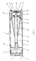
- FIG. 2 represents a telescoped munition of which the case 2 is closed at its rear part by a plug 3 and at its front part by another plug formed by a ring 4.
- the projectile 10 comprises a sub-calibrated bar 32 disposed in a shoe of caliber 33.
- the under-calibrated bar carries a tail unit 27 at its rear part.
- the belt 11 is in abutment against the ring front 4.
- the projectile is held axially and radially with respect to the case by holding means which may include a rear wedge 28 and an engaged elastic ring in the front ring (not shown here).
- Shoe 33 of the projectile carries an anti-wear back-up 26 deposited in a front pocket 29 which thus constitutes a reception area for back-up.
- the backup is in place by casting.
- a protective glitter can be put in place after depositing the extra in the pocket to ensure its symmetrical layer maintenance during the phases of storage.
- the shoe also has a rear layer 24 anti-wear supplement placed on a reception area outer shoe behind the belt.
- the front ring 4 is closed by a seal 21 glued at a counterbore 22.
- the cover carries an extension cylindrical 30 having an internal housing 31 which constitutes a reception area for anti-wear back-up 26.
- a closing straw can be put in place after depositing the extra to ensure its maintenance in the lid in a symmetrical layer.
- the cover is broken by the projectile during the firing of the ammunition, and the add-on 26 it contains found distributed in the tube at the front of the projectile and driven by it.
- the extra pocket 29 will fall into place more gradually along the tube and maximum in the second half of it when the shot is made with a striped tube. It plays the role of the added headdress described previously and will preferably consist of fat.
- the addition of the rear layer may include titanium dioxide, tungsten trioxide or talc.
- Figure 3 also shows a telescoped munition whose case 2 is closed at its rear part by a plug 3 and at its front part by a ring 4 closed by a cover 21 made of plastic.
- Projectile 10 includes an under-calibrated bar 32 placed in a shoe 33 to the caliber.
- the projectile is here gyrostabilized and the shoe has a bottom 33a produced by example in steel and on which a shirt 33b is molded made of plastic.
- the belt 11 bears against the front ring 4, guidance of the projectile in the ring is also ensured by cylindrical spans 34 and 35.
- a peripheral groove 36 is arranged on the shirt 33b of the shoe 33 in front of the belt 11.
- This groove is delimited by the ranges 34 and 35, it is intended to lighten the hoof and facilitate its burst at the exit of the barrel of the weapon. It constitutes a reception area for anti-wear back-up 26.
- the anti-wear back-up is maintained by the surface inner cylindrical of the ring and it retains a even distribution in the case during storage of ammunition.
- the extra deposited in the throat plays the role of the addition of the front layer described previously with reference in Figure 1 (it may consist of grease or a talc / wax mixture). This supplement spreads in particular from beginning of the tube and before engagement of the belt.
- the shoe 33 of the projectile also carries a booster anti-wear 26 deposited in a reception area which is a front pocket 29.
- This backup plays the role of the backup cap described above with reference to Figure 1. It is gradually spread along the tube and as much as possible in the second half of it following efforts developed centrifuges (it will preferably consist of fat).
- the shoe finally carries an additional rear layer 24 anti-wear deposited on a conical bottom receiving area 33a of the hoof behind the belt.
- This supplement may contain titanium dioxide, tungsten trioxide or talc. It reduces the erosive effects of hot gases.
- the embodiment of Figure 3 can also be implemented with a non-telescoped projectile.
- the case will be crimped on a throat of the projectile disposed behind the belt.
- the projectile will wear a rear layer 24 of an anti-wear supplement reducing the erosive effects of gases (titanium dioxide or tungsten trioxide associated with wax). He will wear also in the peripheral groove 36 (in front of the belt) anti-wear and / or anti-friction support as talc associated with wax.
- This supplement will be widespread in the weapon barrel from the start of the barrel and before engagement of the belt.
- the projectile can finally carry an anti-wear booster 26 deposited in the front pocket 29.
- This make-up will be a friction-reducing material (such as grease), and apart from its arrangement in pocket 29, it will be distributed maximum in the second half of the tube.
- the back-ups arranged in the groove 36 and / or in the pocket 29 will be protected by glitter.
Landscapes
- Engineering & Computer Science (AREA)
- General Engineering & Computer Science (AREA)
- Aiming, Guidance, Guns With A Light Source, Armor, Camouflage, And Targets (AREA)
- Lubricants (AREA)
Description
- la figure 1a représente en coupe axiale une munition télescopée selon un premier mode de réalisation de l'invention,
- la figure 1b est une coupe suivant le plan AA de la figure 1a,
- la figure 2 représente en coupe axiale une munition télescopée selon un deuxième mode de réalisation de l'invention,
- la figure 3 représente en coupe axiale une munition télescopée selon un troisième mode de réalisation de l'invention.
- comme matériau déposé par la coiffe une composition permettant de diminuer le frottement (telle une graisse),
- comme matériau pour la couche avant une composition pour diminuer le frottement (telle une graisse) ou une composition anti-usure/anti-frottement comme le talc associé à la cire,
- comme matériau pour la couche arrière un appoint anti-usure classique permettant de diminuer les effets érosifs des gaz propulsifs chauds (comme le dioxyde de titane ou le trioxyde de tungstène associés à la cire).
Claims (10)
- Munition (1) comportant un étui (2) contenant un chargement propulsif et un projectile (10), présentant un corps et une ceinture d'étanchéité (11) aux gaz propulsifs, le projectile étant télescopé à l'intérieur de l'étui et maintenu par une coiffe (14) solidaire de celui-ci et ajustée dans une bague avant (4) fermant l'étui, un appoint anti-usure entraíné par le projectile étant disposé en avant de celui-ci lors du tir, caractérisée en ce que l'appoint anti-usure (26) est disposé au niveau d'au moins une zone de réception portée par la coiffe (14) et se trouve donc entraíné par le projectile lors du tir.
- Munition selon la revendication 1, caractérisée en ce que la coiffe (14) présente une zone annulaire dans laquelle sont aménagés au moins deux alésages (17) parallèles à l'axe de la munition et régulièrement répartis angulairement, les alésages communiquant avec une surface cylindrique externe de la coiffe (14) par des trous (20) et en ce que l'appoint anti-usure (26) est placé dans les alésages (17).
- Munition (1) selon la revendication 1 et dans laquelle le projectile comporte un barreau sous-calibré (32) disposé dans un sabot (33) au calibre, caractérisé en ce que l'appoint anti-usure (26) est disposé au niveau d'au moins une zone de réception qui comprend une poche avant (29) aménagée sur le sabot (33), l'appoint se trouvant donc entraíné par le projectile lors du tir.
- Munition (1) selon la revendication 1 et dans laquelle le projectile comporte un barreau sous-calibré (32) disposé dans un sabot (33) au calibre, caractérisé en ce que l'appoint anti-usure (26) est disposé au niveau d'au moins une zone de réception qui comprend au moins un logement périphérique (36) aménagé sur le sabot en avant de la ceinture (11), l'appoint se trouvant donc entraíné par le projectile lors du tir.
- Munition (1) selon la revendication 1 et dans laquelle l'étui est fermé par un bouchon formé par une bague avant (4) obturée de façon étanche par un opercule (21), caractérisée en ce que l'appoint anti-usure (26) est disposé au niveau d'au moins une zone de réception qui comprend l'opercule (21), l'appoint se trouvant donc entraíné par le projectile lors du tir.
- Munition selon une des revendications 1 à 6, caractérisé en ce qu'une couche avant (23) d'appoint anti-usure est déposée sur au moins une zone de réception qui est le corps même du projectile (10) en avant de la ceinture (11).
- Munition selon une des revendications 1 à 6, caractérisé en ce qu'une couche arrière (24) d'appoint anti-usure est déposée sur au moins une zone de réception qui est le corps même du projectile (10) en arrière de la ceinture (11).
- Munition (1) comportant un étui (2) contenant un chargement propulsif et un projectile (10), présentant un corps et une ceinture d'étanchéité (11) aux gaz propulsifs, caractérisée en ce qu'elle comporte au moins deux zones de réception portant un appoint anti-usure, zones solidaires du projectile (10) ou susceptibles d'être entraínées par lui lors du tir, les matériaux constituant les appoints anti-usure déposés dans chacune des deux zones de réception étant de natures différentes.
- Munition selon la revendications 8, caractérisée en ce qu'une zone de réception se trouve en avant de la ceinture et l'autre en arrière de la ceinture.
- Munition selon la revendication 9, caractérisée en ce que le ou les matériaux disposés en avant de la ceinture sont des compositions permettant de diminuer le frottement et/ou l'usure, et le ou les matériaux disposés en arrière de la ceinture sont des compositions diminuant les effets érosifs des gaz chauds.
Applications Claiming Priority (2)
| Application Number | Priority Date | Filing Date | Title |
|---|---|---|---|
| FR9403064 | 1994-03-16 | ||
| FR9403064A FR2717570B1 (fr) | 1994-03-16 | 1994-03-16 | Munition comportant un appoint anti-usure. |
Publications (2)
| Publication Number | Publication Date |
|---|---|
| EP0674150A1 EP0674150A1 (fr) | 1995-09-27 |
| EP0674150B1 true EP0674150B1 (fr) | 1999-01-20 |
Family
ID=9461102
Family Applications (1)
| Application Number | Title | Priority Date | Filing Date |
|---|---|---|---|
| EP19950400557 Expired - Lifetime EP0674150B1 (fr) | 1994-03-16 | 1995-03-15 | Munition comportant un appoint anti-usure |
Country Status (3)
| Country | Link |
|---|---|
| EP (1) | EP0674150B1 (fr) |
| DE (1) | DE69507356T2 (fr) |
| FR (1) | FR2717570B1 (fr) |
Family Cites Families (8)
| Publication number | Priority date | Publication date | Assignee | Title |
|---|---|---|---|---|
| FR672702A (fr) * | 1928-07-19 | 1930-01-06 | Schneider Et Cie | Dispositif pour la lubrification de l'âme des canons par l'action du projectile surles rayures |
| FR766414A (fr) * | 1934-10-27 | 1934-06-28 | Enveloppe pour projectile avec chambre compressible et lubrifiante | |
| FR825752A (fr) * | 1937-08-19 | 1938-03-14 | Graissage automatique des tubes de canons et obus disposés pour obtenir ce résultat | |
| GB950607A (en) * | 1959-08-14 | 1964-02-26 | Military Training Device Co Ak | Improvements in or relating to ammunition cartridges |
| US4715284A (en) * | 1986-11-24 | 1987-12-29 | Ford Aerospace & Communications Corp. | Telescoped ammunition construction for reducing barrel erosion |
| FR2647891B1 (fr) * | 1989-06-01 | 1994-05-20 | Etat Francais Delegue Armement | Dispositif de maintien d'un projectile sous-calibre relativement a l'enveloppe d'une munition telescopee |
| DE4018386A1 (de) * | 1990-06-08 | 1991-12-12 | Rheinmetall Gmbh | Segmentierter treibkaefig mit additiv |
| FR2679991B1 (fr) * | 1991-07-31 | 1993-10-29 | Giat Industries | Perfectionnements apportes a une munition en particulier du type telescope. |
-
1994
- 1994-03-16 FR FR9403064A patent/FR2717570B1/fr not_active Expired - Fee Related
-
1995
- 1995-03-15 DE DE1995607356 patent/DE69507356T2/de not_active Expired - Fee Related
- 1995-03-15 EP EP19950400557 patent/EP0674150B1/fr not_active Expired - Lifetime
Also Published As
| Publication number | Publication date |
|---|---|
| FR2717570A1 (fr) | 1995-09-22 |
| DE69507356D1 (de) | 1999-03-04 |
| DE69507356T2 (de) | 1999-06-02 |
| EP0674150A1 (fr) | 1995-09-27 |
| FR2717570B1 (fr) | 1996-05-10 |
Similar Documents
| Publication | Publication Date | Title |
|---|---|---|
| EP1092940B1 (fr) | Dispositif d'allumage pour un chargement propulsif | |
| EP0905473B1 (fr) | Projectile d'artillerie de campagne de gros calibre à longue portée | |
| CA1333543C (fr) | Projectile destine a etre tire par une arme a feu | |
| EP0640205B1 (fr) | Etui pour munition de type telescopee | |
| FR2529319A1 (fr) | Munition comportant une charge propulsive et un projectile stabilise par ailettes | |
| EP0180515B1 (fr) | Dispositif pour réduire la trainée des munitions et munitions aptes à le recevoir | |
| EP0293295A1 (fr) | Perfectionnements apportés aux projectiles perforants | |
| EP0572643B1 (fr) | Tube douille pour grenade a fusil pouvant retenir les fragments de la balle | |
| FR2679993A1 (fr) | Munition, en particulier du type telescope. | |
| EP0737298B1 (fr) | Balle de chasse a fleche telescopee, comportant un sous-projectile associe a un lanceur | |
| EP0314547B1 (fr) | Chargement propulsif pour munition comportant un projectile empenné ainsi que son procédé de réalisation | |
| EP1181498B1 (fr) | Tube allumeur pour une munition d'artillerie | |
| EP0659264B1 (fr) | Dispositif d'etancheite aux gaz de propulsion pour munitions d'artillerie | |
| EP0401115B1 (fr) | Dispositif de maintien d'un projectile sous calibré relativement à l'enveloppe d'une munition télescopée | |
| EP1549901B1 (fr) | Ceinture d'etancheite pour projectile et munition equipee d'une telle ceinture | |
| FR2679994A1 (fr) | Dispositif d'allumage de la charge propulsive d'une munition, notamment telescopee, et munition initiee par un tel dispositif d'allumage. | |
| EP0401114B1 (fr) | Dispositif de maintien d'un projectile relativement à l'enveloppe d'une munition télescopée | |
| EP0268535B1 (fr) | Ceinture dérapante pour projectile de tout calibre | |
| FR2665762A1 (fr) | Projectiles. | |
| EP0674150A1 (fr) | Munition comportant un appoint anti-usure | |
| FR2774162A1 (fr) | Projectile a guide conique polygonal pour arme a feu a canon raye, et munition comportant un tel projectile | |
| FR2719373A1 (fr) | Dispositif de propulsion à portées variables pour grenade anti-émeutes. | |
| WO1991002211A1 (fr) | Perfectionnements apportes aux munitions destinees a etre tirees par une arme a canon lisse | |
| EP0775887B1 (fr) | Arrêtoir pour un étui de charge explosive | |
| FR2502766A1 (fr) | Canon d'arme a feu a chambre allongee |
Legal Events
| Date | Code | Title | Description |
|---|---|---|---|
| PUAI | Public reference made under article 153(3) epc to a published international application that has entered the european phase |
Free format text: ORIGINAL CODE: 0009012 |
|
| AK | Designated contracting states |
Kind code of ref document: A1 Designated state(s): BE CH DE ES GB IT LI NL |
|
| 17P | Request for examination filed |
Effective date: 19951110 |
|
| 17Q | First examination report despatched |
Effective date: 19970716 |
|
| GRAG | Despatch of communication of intention to grant |
Free format text: ORIGINAL CODE: EPIDOS AGRA |
|
| GRAG | Despatch of communication of intention to grant |
Free format text: ORIGINAL CODE: EPIDOS AGRA |
|
| GRAH | Despatch of communication of intention to grant a patent |
Free format text: ORIGINAL CODE: EPIDOS IGRA |
|
| GRAH | Despatch of communication of intention to grant a patent |
Free format text: ORIGINAL CODE: EPIDOS IGRA |
|
| GRAA | (expected) grant |
Free format text: ORIGINAL CODE: 0009210 |
|
| AK | Designated contracting states |
Kind code of ref document: B1 Designated state(s): BE CH DE ES GB IT LI NL |
|
| PG25 | Lapsed in a contracting state [announced via postgrant information from national office to epo] |
Ref country code: NL Free format text: LAPSE BECAUSE OF FAILURE TO SUBMIT A TRANSLATION OF THE DESCRIPTION OR TO PAY THE FEE WITHIN THE PRESCRIBED TIME-LIMIT Effective date: 19990120 Ref country code: IT Free format text: LAPSE BECAUSE OF FAILURE TO SUBMIT A TRANSLATION OF THE DESCRIPTION OR TO PAY THE FEE WITHIN THE PRE;WARNING: LAPSES OF ITALIAN PATENTS WITH EFFECTIVE DATE BEFORE 2007 MAY HAVE OCCURRED AT ANY TIME BEFORE 2007. THE CORRECT EFFECTIVE DATE MAY BE DIFFERENT FROM THE ONE RECORDED.SCRIBED TIME-LIMIT Effective date: 19990120 Ref country code: ES Free format text: THE PATENT HAS BEEN ANNULLED BY A DECISION OF A NATIONAL AUTHORITY Effective date: 19990120 |
|
| REG | Reference to a national code |
Ref country code: CH Ref legal event code: EP |
|
| GBT | Gb: translation of ep patent filed (gb section 77(6)(a)/1977) |
Effective date: 19990128 |
|
| REF | Corresponds to: |
Ref document number: 69507356 Country of ref document: DE Date of ref document: 19990304 |
|
| PG25 | Lapsed in a contracting state [announced via postgrant information from national office to epo] |
Ref country code: LI Free format text: LAPSE BECAUSE OF NON-PAYMENT OF DUE FEES Effective date: 19990331 Ref country code: CH Free format text: LAPSE BECAUSE OF NON-PAYMENT OF DUE FEES Effective date: 19990331 Ref country code: BE Free format text: LAPSE BECAUSE OF NON-PAYMENT OF DUE FEES Effective date: 19990331 |
|
| PG25 | Lapsed in a contracting state [announced via postgrant information from national office to epo] |
Ref country code: DE Free format text: LAPSE BECAUSE OF FAILURE TO SUBMIT A TRANSLATION OF THE DESCRIPTION OR TO PAY THE FEE WITHIN THE PRESCRIBED TIME-LIMIT Effective date: 19990421 |
|
| NLV1 | Nl: lapsed or annulled due to failure to fulfill the requirements of art. 29p and 29m of the patents act | ||
| BERE | Be: lapsed |
Owner name: CTA INTERNATIONAL Effective date: 19990331 |
|
| REG | Reference to a national code |
Ref country code: CH Ref legal event code: PL |
|
| PLBE | No opposition filed within time limit |
Free format text: ORIGINAL CODE: 0009261 |
|
| STAA | Information on the status of an ep patent application or granted ep patent |
Free format text: STATUS: NO OPPOSITION FILED WITHIN TIME LIMIT |
|
| 26N | No opposition filed | ||
| REG | Reference to a national code |
Ref country code: GB Ref legal event code: IF02 |
|
| PGFP | Annual fee paid to national office [announced via postgrant information from national office to epo] |
Ref country code: GB Payment date: 20050225 Year of fee payment: 11 Ref country code: DE Payment date: 20050225 Year of fee payment: 11 |
|
| PG25 | Lapsed in a contracting state [announced via postgrant information from national office to epo] |
Ref country code: GB Free format text: LAPSE BECAUSE OF NON-PAYMENT OF DUE FEES Effective date: 20060315 |
|
| GBPC | Gb: european patent ceased through non-payment of renewal fee |
Effective date: 20060315 |