EP0674128B1 - Backflow preventing combination for vehicle fuel tanks - Google Patents
Backflow preventing combination for vehicle fuel tanks Download PDFInfo
- Publication number
- EP0674128B1 EP0674128B1 EP95102631A EP95102631A EP0674128B1 EP 0674128 B1 EP0674128 B1 EP 0674128B1 EP 95102631 A EP95102631 A EP 95102631A EP 95102631 A EP95102631 A EP 95102631A EP 0674128 B1 EP0674128 B1 EP 0674128B1
- Authority
- EP
- European Patent Office
- Prior art keywords
- tank
- obturator
- tubular body
- bell
- skirt
- Prior art date
- Legal status (The legal status is an assumption and is not a legal conclusion. Google has not performed a legal analysis and makes no representation as to the accuracy of the status listed.)
- Expired - Lifetime
Links
- 239000002828 fuel tank Substances 0.000 title claims description 7
- 239000000446 fuel Substances 0.000 claims description 21
- 239000000945 filler Substances 0.000 claims description 11
- 238000007789 sealing Methods 0.000 claims description 6
- 239000000463 material Substances 0.000 claims description 4
- 239000004033 plastic Substances 0.000 claims description 4
- 229920003023 plastic Polymers 0.000 claims description 4
- 230000007423 decrease Effects 0.000 claims description 2
- 125000006850 spacer group Chemical group 0.000 claims description 2
- 238000006424 Flood reaction Methods 0.000 description 2
- 238000007664 blowing Methods 0.000 description 2
- 230000002706 hydrostatic effect Effects 0.000 description 2
- 238000004519 manufacturing process Methods 0.000 description 2
- DHKHKXVYLBGOIT-UHFFFAOYSA-N 1,1-Diethoxyethane Chemical compound CCOC(C)OCC DHKHKXVYLBGOIT-UHFFFAOYSA-N 0.000 description 1
- 239000011354 acetal resin Substances 0.000 description 1
- 238000000071 blow moulding Methods 0.000 description 1
- 230000002401 inhibitory effect Effects 0.000 description 1
- 238000003780 insertion Methods 0.000 description 1
- 230000037431 insertion Effects 0.000 description 1
- 239000007788 liquid Substances 0.000 description 1
- 238000000465 moulding Methods 0.000 description 1
- 238000013021 overheating Methods 0.000 description 1
- 230000002093 peripheral effect Effects 0.000 description 1
- 229920006324 polyoxymethylene Polymers 0.000 description 1
- 230000000630 rising effect Effects 0.000 description 1
Images

Classifications
-
- F—MECHANICAL ENGINEERING; LIGHTING; HEATING; WEAPONS; BLASTING
- F16—ENGINEERING ELEMENTS AND UNITS; GENERAL MEASURES FOR PRODUCING AND MAINTAINING EFFECTIVE FUNCTIONING OF MACHINES OR INSTALLATIONS; THERMAL INSULATION IN GENERAL
- F16K—VALVES; TAPS; COCKS; ACTUATING-FLOATS; DEVICES FOR VENTING OR AERATING
- F16K15/00—Check valves
- F16K15/02—Check valves with guided rigid valve members
- F16K15/021—Check valves with guided rigid valve members the valve member being a movable body around which the medium flows when the valve is open
-
- B—PERFORMING OPERATIONS; TRANSPORTING
- B60—VEHICLES IN GENERAL
- B60K—ARRANGEMENT OR MOUNTING OF PROPULSION UNITS OR OF TRANSMISSIONS IN VEHICLES; ARRANGEMENT OR MOUNTING OF PLURAL DIVERSE PRIME-MOVERS IN VEHICLES; AUXILIARY DRIVES FOR VEHICLES; INSTRUMENTATION OR DASHBOARDS FOR VEHICLES; ARRANGEMENTS IN CONNECTION WITH COOLING, AIR INTAKE, GAS EXHAUST OR FUEL SUPPLY OF PROPULSION UNITS IN VEHICLES
- B60K15/00—Arrangement in connection with fuel supply of combustion engines or other fuel consuming energy converters, e.g. fuel cells; Mounting or construction of fuel tanks
- B60K15/03—Fuel tanks
- B60K15/04—Tank inlets
Definitions
- the present invention relates to a backflow preventing combination for vehicle fuel tanks, comprising an upright portion of a filler pipe and a non-return valve enclosed within the said upright portion.
- Prior art non-return valves which comprise a tubular valve body fitted in the upright portion of the filler pipe, an internal annular valve seat facing the tank, and an obturator which is imprisoned in a portion of the tubular body between the seat and the end of the body nearer the tank so as to be freely slidable in the tubular body and capable of engaging the seat under the action of the fuel should this blow back up the filling pipe as a result of an excess of pressure in the tank.
- the obturator is constituted by a hollow ball made of plastics material contained in a cage.
- a first disadvantage is that the ball tends to crack and fill with fuel, becoming heavier to a point at which the force exerted by fuel blowing back from the tank cannot raise it high enough to engage the valve seat.
- the object of the invention is to provide a backflow preventing combination of the type mentioned above which overcomes the two disadvantages described and is both easy to manufacture and cheaper than prior art valves.
- the obturator of the non-return valve is fundamentally different from a ball obturator in that, as it is open at the bottom, it is unable to retain liquid fuel.
- this fuel floods the cavity in the obturator and exerts both a hydrostatic and a hydrodynamic upward thrust on it. This double thrust ensures that the valve closes effectively.
- the blow-back of fuel stops the fuel flows back into the tank.
- a bell-shaped obturator according to the invention is suitable for moulding in two-half-moulds or dies, the junction of which is not in correspondence with the sealing surface which cooperates with the valve seat. Any seam left by the junction between the two dies will be in a region of the obturator which has no sealing function.
- This known valve comprises a tubular valve body adapted to be fitted in a fuel tank at a lower terminal end of a filler pipe in such a position that the longitudinal axis of the valve body is substantially horizontal.
- the valve body has an internal annular valve seat facing into the tank.
- An obturator is imprisoned in a portion of the tubular valve body between the valve seat and the end of the body nearer the tank so as to be slidable in the valve body.
- the tubular valve body contains a spring for normally biasing the obturator against the valve seat so as to define a "normally closed” position.
- the obturator is constituted by a bell-shaped element which is open towards the tank and has a skirt spaced radially from the surrounding wall of the tubular body.
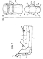
- a fuel tank T for petrol, diesel or the like
- a filler pipe P closed by a cap C.
- a non-return valve V is fitted in the filler pipe P.
- L indicates the level of fuel in the tank T while S indicates the space above the level L.
- the non-return valve V is to prevent just such an occurrence by preventing the fuel from rising up the filler pipe P as a result of the high pressure in the space S but to allow the tank T to be filled in any case.
- a non-return valve comprises only two parts made of fuel-resistant plastics material, for example an acetal resin.
- One of these parts, indicated 10, is a tubular valve body which can be fitted in known manner into the filler pipe P of Figure 1.
- the obturator 12 is imprisoned in the tubular body 10 in a way which will be clarified below.
- the body 10 has an inner, essentially frusto-conical annular valve seat 14 (Figure 2) and is installed with the seat facing towards the tank.
- the obturator 12 which will now be described, is imprisoned in a portion of the tubular body 10 between the seat 14 and the end of the body 10 which, when this is fitted in the vehicle, is the lowermost and faces into the tank.
- the obturator 12 is constituted by a bell-shaped element opening towards the tank.
- the skirt of the bell-shaped element 12 is indicated 16 and the end wall is indicated 18.
- the outside of the skirt 16 has spacer ribs 20 which slidably engage the surrounding wall of the tubular body 10.
- the ribs 20 maintain the obturator 12 coaxially in, and spaced radially from the surrounding wall of the body 10 so as to allow fuel to flow into the tank during refuelling.
- the end wall 18 is, to advantage, ogival, as shown in the drawings.
- the periphery of the ogival wall 18 defines an annular sealing surface shaped to cooperate with the annular seat 14.
- the ribs 20 In order to hold the obturator 12 slidably imprisoned in the tubular body 10, the ribs 20 have projections 22 of substantially saw-tooth profile in longitudinal section. This profile is defined by a straight edge 22a and a ramp edge 22b.
- the straight edge 22a faces the open end of the skirt 16 and the height of the ramp edge 22b decreases from the end of the straight edge 22a towards the opposite end of the skirt 16.
- Apertures 24 are formed in the peripheral wall of the tubular body 10 and the projections 22 are permanently engaged therein.
- the tubular body 10 and the obturator 12 are permanently interconnected, owing to the fact that the straight edges 22a of the projections 22 prevent the obturator 12 from being extracted from the fixed body since, when the valve is open, the straight edges 22a bear against the corresponding lower edges of the apertures 24.
- a bell obturator like the one illustrated can be injection-moulded in two half-moulds or dies, the junction between which is remote from the sealing surface defined by the ogival portion 18.
- the join is in the position indicated by the line 26 of Figure 3, thus forming a harmless seam.
- this line 26 is in the portion immediately below the projections 22 of the ribs 20.
Landscapes
- Engineering & Computer Science (AREA)
- General Engineering & Computer Science (AREA)
- Mechanical Engineering (AREA)
- Life Sciences & Earth Sciences (AREA)
- Sustainable Development (AREA)
- Sustainable Energy (AREA)
- Chemical & Material Sciences (AREA)
- Combustion & Propulsion (AREA)
- Transportation (AREA)
- Cooling, Air Intake And Gas Exhaust, And Fuel Tank Arrangements In Propulsion Units (AREA)
Description
- The present invention relates to a backflow preventing combination for vehicle fuel tanks, comprising an upright portion of a filler pipe and a non-return valve enclosed within the said upright portion.
- Prior art non-return valves are already known which comprise a tubular valve body fitted in the upright portion of the filler pipe, an internal annular valve seat facing the tank, and an obturator which is imprisoned in a portion of the tubular body between the seat and the end of the body nearer the tank so as to be freely slidable in the tubular body and capable of engaging the seat under the action of the fuel should this blow back up the filling pipe as a result of an excess of pressure in the tank.
- In such known non-return valves, the obturator is constituted by a hollow ball made of plastics material contained in a cage.
- This known design has two disadvantages.
- A first disadvantage is that the ball tends to crack and fill with fuel, becoming heavier to a point at which the force exerted by fuel blowing back from the tank cannot raise it high enough to engage the valve seat.
- Another disadvantage is that the hollow plastics balls are made by blow-moulding in a mould constituted by two halves which leave a seam around a meridian of the ball. When the seam engages the valve seat, the ball does not seal the valve satisfactorily. On the other hand, in a low-cost manufacturing process, it is not practical to eliminate this seam.
- The object of the invention is to provide a backflow preventing combination of the type mentioned above which overcomes the two disadvantages described and is both easy to manufacture and cheaper than prior art valves.
- This object is achieved according to the present invention by means of a backflow preventing combination according to Claim 1.
- In a combination according to the invention, the obturator of the non-return valve is fundamentally different from a ball obturator in that, as it is open at the bottom, it is unable to retain liquid fuel. When a spurt of fuel reaches the obturator, this fuel floods the cavity in the obturator and exerts both a hydrostatic and a hydrodynamic upward thrust on it. This double thrust ensures that the valve closes effectively. When the blow-back of fuel stops, the fuel flows back into the tank.
- As will be better understood from the description with reference to the drawings, a bell-shaped obturator according to the invention is suitable for moulding in two-half-moulds or dies, the junction of which is not in correspondence with the sealing surface which cooperates with the valve seat. Any seam left by the junction between the two dies will be in a region of the obturator which has no sealing function.
- Document US-A-5 282 497 discloses a non-return valve for inhibiting over-filling of a vehicle fuel tank.
- This known valve comprises a tubular valve body adapted to be fitted in a fuel tank at a lower terminal end of a filler pipe in such a position that the longitudinal axis of the valve body is substantially horizontal.
- The valve body has an internal annular valve seat facing into the tank.
- An obturator is imprisoned in a portion of the tubular valve body between the valve seat and the end of the body nearer the tank so as to be slidable in the valve body.
- The tubular valve body contains a spring for normally biasing the obturator against the valve seat so as to define a "normally closed" position.
- The obturator is constituted by a bell-shaped element which is open towards the tank and has a skirt spaced radially from the surrounding wall of the tubular body.
- Additional characteristics and advantages of the invention will become apparent from the following detailed description of a preferred but non-limitative embodiment, illustrated in the appended drawings, in which:
- Figure 1 is a partially sectioned elevation view of a fuel tank with a filling pipe incorporating a non-return valve;
- Figure 2 is a longitudinal section of the non-return valve;
- Figure 3 is an exploded perspective view of this valve, and
- Figure 4 is an enlarged cross section along the plane indicated IV-IV in Figure 2.
-
- With reference to Figure 1, a fuel tank T (for petrol, diesel or the like) has a filler pipe P closed by a cap C. A non-return valve V is fitted in the filler pipe P. L indicates the level of fuel in the tank T while S indicates the space above the level L.
- If the pressure in the space S rises above atmospheric pressure, for instance as a result of overheating due to the vehicle being stopped in the sun, this pressure tends to make the fuel rise up the pipe P. Should the cap C be removed under these conditions for refilling with fuel, in the absence of the non-return valve V, the fuel could overflow, even violently, from the mouth of the pipe P. The purpose of the non-return valve V is to prevent just such an occurrence by preventing the fuel from rising up the filler pipe P as a result of the high pressure in the space S but to allow the tank T to be filled in any case.
- With reference to Figures 2 to 4, a non-return valve according to the invention comprises only two parts made of fuel-resistant plastics material, for example an acetal resin. One of these parts, indicated 10, is a tubular valve body which can be fitted in known manner into the filler pipe P of Figure 1. The other part, indicated 12, is an obturator.
- The
obturator 12 is imprisoned in thetubular body 10 in a way which will be clarified below. - The
body 10 has an inner, essentially frusto-conical annular valve seat 14 (Figure 2) and is installed with the seat facing towards the tank. - The
obturator 12, which will now be described, is imprisoned in a portion of thetubular body 10 between theseat 14 and the end of thebody 10 which, when this is fitted in the vehicle, is the lowermost and faces into the tank. - As can be seen in Figures 2 and 3, the
obturator 12 is constituted by a bell-shaped element opening towards the tank. - The skirt of the bell-
shaped element 12 is indicated 16 and the end wall is indicated 18. - The outside of the
skirt 16 hasspacer ribs 20 which slidably engage the surrounding wall of thetubular body 10. Theribs 20 maintain theobturator 12 coaxially in, and spaced radially from the surrounding wall of thebody 10 so as to allow fuel to flow into the tank during refuelling. - In order to facilitate the flow of fuel into the tank, the
end wall 18 is, to advantage, ogival, as shown in the drawings. - The periphery of the
ogival wall 18 defines an annular sealing surface shaped to cooperate with theannular seat 14. - In order to hold the
obturator 12 slidably imprisoned in thetubular body 10, theribs 20 haveprojections 22 of substantially saw-tooth profile in longitudinal section. This profile is defined by astraight edge 22a and aramp edge 22b. - The
straight edge 22a faces the open end of theskirt 16 and the height of theramp edge 22b decreases from the end of thestraight edge 22a towards the opposite end of theskirt 16. -
Apertures 24 are formed in the peripheral wall of thetubular body 10 and theprojections 22 are permanently engaged therein. - As a result of this, no additional parts are needed to hold the obturator in the valve body whereas, in the prior art ball valves, a third, cage element was needed to hold the ball in the valve body.
- The two
parts obturator 12 into thebody 10 in the direction of the arrow A of Figure 2 until theramp edges 22b engage the open lower rim of thebody 10. At this point, thanks to the resilience of the material forming thebody 10, this rim expands in the direction of the arrows B of Figure 2 under the cam action of theinclined edges 22b until theprojections 22 snap-engage theapertures 24. - Once they are snap engaged, the
tubular body 10 and theobturator 12 are permanently interconnected, owing to the fact that thestraight edges 22a of theprojections 22 prevent theobturator 12 from being extracted from the fixed body since, when the valve is open, thestraight edges 22a bear against the corresponding lower edges of theapertures 24. - When the non-return valve is hit by fuel blowing back from the tank, the fuel floods into the
bell 12, urging it upwards with both hydrostatic and hydrodynamic thrust until it reaches the position, illustrated by the broken line in Figure 2, in which it closes the valve. - Once the blow-back ceases, the fuel flows out of the
bell 12 which returns to its position in which the valve is open, as shown by the unbroken line of Figure 2. - A bell obturator like the one illustrated can be injection-moulded in two half-moulds or dies, the junction between which is remote from the sealing surface defined by the
ogival portion 18. To advantage, the join is in the position indicated by theline 26 of Figure 3, thus forming a harmless seam. As can be seen, thisline 26 is in the portion immediately below theprojections 22 of theribs 20.
Claims (5)
- A backflow preventing combination for vehicle fuel tanks, comprising an upright portion of a filler pipe (P) for the tank (T) and a non-return valve (V) enclosed within said upright portion, the valve comprising a tubular valve body (10) fitted in the upright portion of the filler pipe (P) and having an internal annular valve seat (14) facing towards the first side of the filler pipe portion directed towards the tank (T) and an obturator (12) of plastics material imprisoned in a position of the tubular body (10) between the seat (14) and the end of the body (10) nearer the tank (T) so as to be freely slidable in the tubular body and capable of engaging the seat (14) under the action of the fuel when this rises up the filler pipe (P) as a result of an excess of pressure in the tank (T), wherein the obturator is constituted by a bell-shaped element (12) which is open towards the tank (T) and has a skirt (16) spaced radially from the surrounding wall of the tubular body (10) to allow fuel to flow into the tank (T) and having a sealing surface (18) facing the seat (14) and adapted to cooperate therewith.
- A combination according to Claim 1, characterised in that the bell-shaped element (12) constituting the obturator has an ogival end wall (18) the periphery of which defines the said sealing surface.
- A combination according to Claim 1 or Claim 2, characterised in that the skirt (16) of the bell-shaped element (12) has outer spacer ribs (20) which slidably engage the surrounding wall of the tubular body (10), apertures (24) being formed in this surrounding wall in correspondence with the ribs (20) and the ribs (20) having projections (22) which engage the apertures to prevent the bell-shaped element (12) from sliding out of the body (10).
- A combination according to Claim 3, characterised in that the said projections (22) snap engage in the said apertures (24) as a result of resilient expansion of the tubular body (10).
- A combination according to Claim 4, characterised in that the projections (22) are substantially saw-toothed in longitudinal profile, with a straight edge (22a) facing the open end of the skirt (16) and a ramp edge (22b) the height of which decreases from the top of the straight edge (22a) towards the opposite end of the skirt (16) so as to enable the bell-shaped obturator (12) to be snap engaged into the tubular body (10) by the force fitting of the projections (22) through the open end of the skirt (16) into positions in which the projections (22) are in the respective apertures (24).
Applications Claiming Priority (2)
| Application Number | Priority Date | Filing Date | Title |
|---|---|---|---|
| IT94TO000133A IT1266833B1 (en) | 1994-02-28 | 1994-02-28 | RETURN VALVE FOR VEHICLE FUEL TANKS |
| ITTO940133 | 1994-02-28 |
Publications (3)
| Publication Number | Publication Date |
|---|---|
| EP0674128A2 EP0674128A2 (en) | 1995-09-27 |
| EP0674128A3 EP0674128A3 (en) | 1997-04-23 |
| EP0674128B1 true EP0674128B1 (en) | 2001-04-25 |
Family
ID=11412220
Family Applications (1)
| Application Number | Title | Priority Date | Filing Date |
|---|---|---|---|
| EP95102631A Expired - Lifetime EP0674128B1 (en) | 1994-02-28 | 1995-02-24 | Backflow preventing combination for vehicle fuel tanks |
Country Status (4)
| Country | Link |
|---|---|
| EP (1) | EP0674128B1 (en) |
| DE (1) | DE69520764T2 (en) |
| ES (1) | ES2158001T3 (en) |
| IT (1) | IT1266833B1 (en) |
Families Citing this family (6)
| Publication number | Priority date | Publication date | Assignee | Title |
|---|---|---|---|---|
| GB2327741B (en) * | 1997-07-14 | 2000-08-09 | Piolax Inc | Fuel tank fuel supply check valve |
| FR2777229B1 (en) * | 1998-04-10 | 2000-06-09 | Plastic Omnium Cie | NON-RETURN VALVE FOR FUEL TANK |
| WO2011140969A1 (en) * | 2010-05-14 | 2011-11-17 | 厦门松霖科技有限公司 | Backflow preventer |
| DE102011082728A1 (en) * | 2011-09-15 | 2013-03-21 | Robert Bosch Gmbh | Check valve, in particular for a high-pressure fuel pump, and pump with check valve |
| DE102019102724A1 (en) * | 2019-02-04 | 2020-08-06 | Mann+Hummel Gmbh | Valve body for a valve and valve |
| DE102019102729A1 (en) * | 2019-02-04 | 2020-08-06 | Mann+Hummel Gmbh | Valve body for a valve and valve |
Citations (1)
| Publication number | Priority date | Publication date | Assignee | Title |
|---|---|---|---|---|
| US5044389A (en) * | 1990-08-28 | 1991-09-03 | Borg-Warner Automotive, Inc. | High volume fuel vapor release valve |
Family Cites Families (4)
| Publication number | Priority date | Publication date | Assignee | Title |
|---|---|---|---|---|
| US2554053A (en) * | 1947-11-07 | 1951-05-22 | Charles H Hyer | Automatic backwater valve |
| GB983076A (en) * | 1962-02-06 | 1965-02-10 | Neumo Ltd | Fluid valves |
| US4643222A (en) * | 1985-04-17 | 1987-02-17 | Chatleff Controls, Inc. | Check valve |
| US5282497A (en) * | 1992-10-23 | 1994-02-01 | Allen Allison | Fuel delivery and vapor control system for controlling the release of fuel vapors from a vehicle fuel tank |
-
1994
- 1994-02-28 IT IT94TO000133A patent/IT1266833B1/en active IP Right Grant
-
1995
- 1995-02-24 ES ES95102631T patent/ES2158001T3/en not_active Expired - Lifetime
- 1995-02-24 EP EP95102631A patent/EP0674128B1/en not_active Expired - Lifetime
- 1995-02-24 DE DE69520764T patent/DE69520764T2/en not_active Expired - Fee Related
Patent Citations (1)
| Publication number | Priority date | Publication date | Assignee | Title |
|---|---|---|---|---|
| US5044389A (en) * | 1990-08-28 | 1991-09-03 | Borg-Warner Automotive, Inc. | High volume fuel vapor release valve |
Also Published As
| Publication number | Publication date |
|---|---|
| ES2158001T3 (en) | 2001-09-01 |
| ITTO940133A1 (en) | 1995-08-28 |
| IT1266833B1 (en) | 1997-01-21 |
| DE69520764D1 (en) | 2001-05-31 |
| EP0674128A2 (en) | 1995-09-27 |
| DE69520764T2 (en) | 2001-08-30 |
| ITTO940133A0 (en) | 1994-02-28 |
| EP0674128A3 (en) | 1997-04-23 |
Similar Documents
| Publication | Publication Date | Title |
|---|---|---|
| US5577526A (en) | Float valve for fuel tank | |
| EP0667253B1 (en) | Fuel vapour vent assembly with liquid trap | |
| US6058963A (en) | Vehicle refueling valve | |
| US4991615A (en) | Tank pressure control apparatus | |
| US5419378A (en) | Pour spout | |
| US5076333A (en) | Pour spout | |
| US6918405B2 (en) | Fill limit vent valve | |
| US7182109B2 (en) | Filling pipe discharge nozzle | |
| US5044389A (en) | High volume fuel vapor release valve | |
| KR20120047934A (en) | Vent valve | |
| US20030089405A1 (en) | Attachment of fuel vapor vent valve to the inside of a fuel tank | |
| JP2525771Y2 (en) | Automotive fuel backflow prevention device | |
| EP1642760A2 (en) | Fuel tank vent system with variable-height fuel level shut-off port | |
| US8297298B2 (en) | Vent control valve for a fuel tank | |
| US4842152A (en) | Spill proof plug | |
| US20070000542A1 (en) | Fuel tank valve | |
| US4893643A (en) | Tank vapor vent valve assembly with improved overfill protection | |
| US8347914B2 (en) | System for filling a tank | |
| EP0674128A2 (en) | Backflow preventing valve for vehicle fuel tanks | |
| US4579135A (en) | Valve for preventing fuel from flowing from the vent of an automobile fuel tank | |
| US20050028873A1 (en) | Siphonable poppet-type fill tube check valve | |
| US20130187378A1 (en) | Connector for fuel tank | |
| US5775392A (en) | Motor vehicle tank with filling tube vent | |
| EP0674129A2 (en) | Vent and safety roll-over valve for vehicle tanks | |
| US8267113B2 (en) | Safety valve for the venting circuit of a liquid tank |
Legal Events
| Date | Code | Title | Description |
|---|---|---|---|
| PUAI | Public reference made under article 153(3) epc to a published international application that has entered the european phase |
Free format text: ORIGINAL CODE: 0009012 |
|
| AK | Designated contracting states |
Kind code of ref document: A2 Designated state(s): DE ES FR GB IT |
|
| PUAL | Search report despatched |
Free format text: ORIGINAL CODE: 0009013 |
|
| AK | Designated contracting states |
Kind code of ref document: A3 Designated state(s): DE ES FR GB IT |
|
| 17P | Request for examination filed |
Effective date: 19971014 |
|
| 17Q | First examination report despatched |
Effective date: 19990728 |
|
| RIC1 | Information provided on ipc code assigned before grant |
Free format text: 7F 16K 15/02 A, 7B 60K 15/035 B |
|
| RTI1 | Title (correction) |
Free format text: BACKFLOW PREVENTING COMBINATION FOR VEHICLE FUEL TANKS |
|
| GRAG | Despatch of communication of intention to grant |
Free format text: ORIGINAL CODE: EPIDOS AGRA |
|
| RIC1 | Information provided on ipc code assigned before grant |
Free format text: 7F 16K 15/02 A, 7B 60K 15/035 B |
|
| RTI1 | Title (correction) |
Free format text: BACKFLOW PREVENTING COMBINATION FOR VEHICLE FUEL TANKS |
|
| GRAG | Despatch of communication of intention to grant |
Free format text: ORIGINAL CODE: EPIDOS AGRA |
|
| GRAH | Despatch of communication of intention to grant a patent |
Free format text: ORIGINAL CODE: EPIDOS IGRA |
|
| RAP1 | Party data changed (applicant data changed or rights of an application transferred) |
Owner name: ERSI ITALIA S.P.A. |
|
| GRAH | Despatch of communication of intention to grant a patent |
Free format text: ORIGINAL CODE: EPIDOS IGRA |
|
| GRAA | (expected) grant |
Free format text: ORIGINAL CODE: 0009210 |
|
| AK | Designated contracting states |
Kind code of ref document: B1 Designated state(s): DE ES FR GB IT |
|
| ITF | It: translation for a ep patent filed | ||
| REF | Corresponds to: |
Ref document number: 69520764 Country of ref document: DE Date of ref document: 20010531 |
|
| ET | Fr: translation filed | ||
| REG | Reference to a national code |
Ref country code: ES Ref legal event code: FG2A Ref document number: 2158001 Country of ref document: ES Kind code of ref document: T3 |
|
| REG | Reference to a national code |
Ref country code: GB Ref legal event code: IF02 |
|
| PLBE | No opposition filed within time limit |
Free format text: ORIGINAL CODE: 0009261 |
|
| STAA | Information on the status of an ep patent application or granted ep patent |
Free format text: STATUS: NO OPPOSITION FILED WITHIN TIME LIMIT |
|
| 26N | No opposition filed | ||
| PGFP | Annual fee paid to national office [announced via postgrant information from national office to epo] |
Ref country code: ES Payment date: 20030107 Year of fee payment: 9 |
|
| PGFP | Annual fee paid to national office [announced via postgrant information from national office to epo] |
Ref country code: GB Payment date: 20030116 Year of fee payment: 9 |
|
| PGFP | Annual fee paid to national office [announced via postgrant information from national office to epo] |
Ref country code: DE Payment date: 20030120 Year of fee payment: 9 |
|
| PGFP | Annual fee paid to national office [announced via postgrant information from national office to epo] |
Ref country code: FR Payment date: 20030228 Year of fee payment: 9 |
|
| PG25 | Lapsed in a contracting state [announced via postgrant information from national office to epo] |
Ref country code: GB Free format text: LAPSE BECAUSE OF NON-PAYMENT OF DUE FEES Effective date: 20040224 |
|
| PG25 | Lapsed in a contracting state [announced via postgrant information from national office to epo] |
Ref country code: ES Free format text: LAPSE BECAUSE OF NON-PAYMENT OF DUE FEES Effective date: 20040225 |
|
| PG25 | Lapsed in a contracting state [announced via postgrant information from national office to epo] |
Ref country code: DE Free format text: LAPSE BECAUSE OF NON-PAYMENT OF DUE FEES Effective date: 20040901 |
|
| GBPC | Gb: european patent ceased through non-payment of renewal fee |
Effective date: 20040224 |
|
| PG25 | Lapsed in a contracting state [announced via postgrant information from national office to epo] |
Ref country code: FR Free format text: LAPSE BECAUSE OF NON-PAYMENT OF DUE FEES Effective date: 20041029 |
|
| REG | Reference to a national code |
Ref country code: FR Ref legal event code: ST |
|
| REG | Reference to a national code |
Ref country code: ES Ref legal event code: FD2A Effective date: 20040225 |
|
| PGFP | Annual fee paid to national office [announced via postgrant information from national office to epo] |
Ref country code: IT Payment date: 20140130 Year of fee payment: 20 |