EP0673339B1 - Spender zum nachfolgenden ausgeben von tabletten - Google Patents
Spender zum nachfolgenden ausgeben von tabletten Download PDFInfo
- Publication number
- EP0673339B1 EP0673339B1 EP94903740A EP94903740A EP0673339B1 EP 0673339 B1 EP0673339 B1 EP 0673339B1 EP 94903740 A EP94903740 A EP 94903740A EP 94903740 A EP94903740 A EP 94903740A EP 0673339 B1 EP0673339 B1 EP 0673339B1
- Authority
- EP
- European Patent Office
- Prior art keywords
- chutes
- dispensing
- wall
- tablet
- tablets
- Prior art date
- Legal status (The legal status is an assumption and is not a legal conclusion. Google has not performed a legal analysis and makes no representation as to the accuracy of the status listed.)
- Expired - Lifetime
Links
- 239000003826 tablet Substances 0.000 claims description 75
- 239000007947 dispensing tablet Substances 0.000 claims description 2
- 238000005192 partition Methods 0.000 description 10
- 239000006187 pill Substances 0.000 description 5
- 238000011282 treatment Methods 0.000 description 4
- 239000003814 drug Substances 0.000 description 3
- 239000000470 constituent Substances 0.000 description 1
- 230000008878 coupling Effects 0.000 description 1
- 238000010168 coupling process Methods 0.000 description 1
- 238000005859 coupling reaction Methods 0.000 description 1
- 238000005096 rolling process Methods 0.000 description 1
Images



Classifications
-
- A—HUMAN NECESSITIES
- A61—MEDICAL OR VETERINARY SCIENCE; HYGIENE
- A61J—CONTAINERS SPECIALLY ADAPTED FOR MEDICAL OR PHARMACEUTICAL PURPOSES; DEVICES OR METHODS SPECIALLY ADAPTED FOR BRINGING PHARMACEUTICAL PRODUCTS INTO PARTICULAR PHYSICAL OR ADMINISTERING FORMS; DEVICES FOR ADMINISTERING FOOD OR MEDICINES ORALLY; BABY COMFORTERS; DEVICES FOR RECEIVING SPITTLE
- A61J7/00—Devices for administering medicines orally, e.g. spoons; Pill counting devices; Arrangements for time indication or reminder for taking medicine
- A61J7/04—Arrangements for time indication or reminder for taking medicine, e.g. programmed dispensers
-
- B—PERFORMING OPERATIONS; TRANSPORTING
- B65—CONVEYING; PACKING; STORING; HANDLING THIN OR FILAMENTARY MATERIAL
- B65D—CONTAINERS FOR STORAGE OR TRANSPORT OF ARTICLES OR MATERIALS, e.g. BAGS, BARRELS, BOTTLES, BOXES, CANS, CARTONS, CRATES, DRUMS, JARS, TANKS, HOPPERS, FORWARDING CONTAINERS; ACCESSORIES, CLOSURES, OR FITTINGS THEREFOR; PACKAGING ELEMENTS; PACKAGES
- B65D83/00—Containers or packages with special means for dispensing contents
- B65D83/04—Containers or packages with special means for dispensing contents for dispensing annular, disc-shaped, spherical or like small articles, e.g. tablets or pills
- B65D83/0445—Containers or packages with special means for dispensing contents for dispensing annular, disc-shaped, spherical or like small articles, e.g. tablets or pills all the articles being stored in individual compartments
- B65D83/0454—Containers or packages with special means for dispensing contents for dispensing annular, disc-shaped, spherical or like small articles, e.g. tablets or pills all the articles being stored in individual compartments the whole forming a circular container with rotating parts
-
- B—PERFORMING OPERATIONS; TRANSPORTING
- B65—CONVEYING; PACKING; STORING; HANDLING THIN OR FILAMENTARY MATERIAL
- B65D—CONTAINERS FOR STORAGE OR TRANSPORT OF ARTICLES OR MATERIALS, e.g. BAGS, BARRELS, BOTTLES, BOXES, CANS, CARTONS, CRATES, DRUMS, JARS, TANKS, HOPPERS, FORWARDING CONTAINERS; ACCESSORIES, CLOSURES, OR FITTINGS THEREFOR; PACKAGING ELEMENTS; PACKAGES
- B65D2583/00—Containers or packages with special means for dispensing contents
- B65D2583/04—For dispensing annular, disc-shaped or spherical or like small articles or tablets
- B65D2583/0404—Indications, e.g. directions for use
- B65D2583/0409—Indications, e.g. directions for use of dates or follow-numbers
-
- B—PERFORMING OPERATIONS; TRANSPORTING
- B65—CONVEYING; PACKING; STORING; HANDLING THIN OR FILAMENTARY MATERIAL
- B65D—CONTAINERS FOR STORAGE OR TRANSPORT OF ARTICLES OR MATERIALS, e.g. BAGS, BARRELS, BOTTLES, BOXES, CANS, CARTONS, CRATES, DRUMS, JARS, TANKS, HOPPERS, FORWARDING CONTAINERS; ACCESSORIES, CLOSURES, OR FITTINGS THEREFOR; PACKAGING ELEMENTS; PACKAGES
- B65D2583/00—Containers or packages with special means for dispensing contents
- B65D2583/04—For dispensing annular, disc-shaped or spherical or like small articles or tablets
- B65D2583/0436—Receiving device other than a removable closure
-
- B—PERFORMING OPERATIONS; TRANSPORTING
- B65—CONVEYING; PACKING; STORING; HANDLING THIN OR FILAMENTARY MATERIAL
- B65D—CONTAINERS FOR STORAGE OR TRANSPORT OF ARTICLES OR MATERIALS, e.g. BAGS, BARRELS, BOTTLES, BOXES, CANS, CARTONS, CRATES, DRUMS, JARS, TANKS, HOPPERS, FORWARDING CONTAINERS; ACCESSORIES, CLOSURES, OR FITTINGS THEREFOR; PACKAGING ELEMENTS; PACKAGES
- B65D2583/00—Containers or packages with special means for dispensing contents
- B65D2583/04—For dispensing annular, disc-shaped or spherical or like small articles or tablets
- B65D2583/0472—For dispensing annular, disc-shaped or spherical or like small articles or tablets characterised by the dispensing action
- B65D2583/0477—For dispensing annular, disc-shaped or spherical or like small articles or tablets characterised by the dispensing action the container is maintained in the same position during the dispensing of several successive articles or doses
- B65D2583/049—One rotational action of a cylindrical, disc-like or sphere-like element around its own axis, e.g. step-by-step, reciprocating
Definitions
- the invention relates to dispensers for consecutive dispensing tablets through a dispensing opening in a fixed order from a cylindrical body defining along its periphery a number of juxtaposed vertical chutes each accommodating a number of tablets piled on edge.
- tablets with varying medicine content must be taken in a fixed order.
- some tablets with one medicine content may be taken one a day for some days and thereafter tablets with another medicine content through the following days and so on.
- dispensers for a consecutive one a day dispensing of 21 to 28 tablets.
- Such dispensers are shaped as flat round boxes with a lid having an opening which may be stepwise clicked along the periphery of the box to consecutively dispense tablets stored lying on their mainly flat side in chambers arranged along the periphery of the box.
- an arrangement of more chambers along the periphery of the box would make it necessary to let the box have a larger diameter, which would make the box less easy to carry in a pocket.
- a doubling of the box diameter would make the box accommodate a double number of tablets, but would quadruple the unused dead space in the middle of the box.
- US-A-3,604,559 discloses a dispenser wherein the tablets are stacked in three layers along the periphery of a box of the kind having a dispensing opening in its lid.
- the tablets are herein piled with their flat sides against each other, the three layers being displaced half a tablet diameter in relation to each other.
- the tablets are accommodated in circular openings provided along the periphery of an individually rotatable disc.
- the tablets in the layers are lying on their flat side along the periphery of the dispenser. A better utilisation of the space may be obtained by putting the tablet on their edge and let them be oriented radially in the dispenser.
- US-A-4 807 757 describes a dispenser according to the first part of claim 1 having along its periphery a number of pill retaining chutes extending axially thereof and wherein the pills are stacked edge to edge.
- Each chute is provided with a dispensing element by the operation of which a pill from the chute in question may be dispensed through a dispensing opening. The pills are not dispensed in any predetermined order.
- a dispenser of the kind according to the first part of claim 1 which dispenser is characterised in that the chutes are designed to orient the tablets radially in the body, that a cup shaped dispensing part has a bottom plate and an upstanding cylindrical wall on this plate, the plate forming a stop at the lower end of the chutes and the cylindrical wall having at its lower end adjacent to the bottom plate a slot forming the dispensing opening allowing a tablet on edge to pass from the outside of the cup into the inner space thereof, that a protrusion above the slot extends radially outwards from the cylindrical wall into the space between a tablet abreast of the slot and a possible overlying tablet in the chute, that a radially outward extending wall adjacent to the slot extends into the lower ends of the chutes that a detent mechanism makes the body and the dispensing part stepwise unidirectionally rotatable in relation to each other, the number of steps corresponding to the number of chutes and the direction of rotation being so that the chutes are moved from
- the stop ring serves a locking of the unidirectional stepwise movement of the dispensing part in relation to the body when the device is turned upside down, as the upper tablets in the chutes will then roll to a position where these tablets are abutting partly the walls of the chutes and partly the walls of the stop ring.
- the chutes may be tapering being widest at their top. Thereby it may be ensured that at least one of the tablets will roll into its locking position in engagement with the stop ring as soon as the dispenser is tilted about 90° from its vertical position.
- the lid part may carry a day ring concentric with this lid part and which by the use of a tool may be rotated relatively to the lid part to set the day for beginning the use of the tablets by making a pointer point at this day.
- the pointer may be secured to the dispensing part to be rotated with this part relatively to the body.
- the lid part may carry a hinged lid which may be closed to cover the day ring and the opening of a cup formed by the cylindric wall and the bottom plate of the dispensing part.
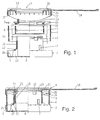
- FIG. 1 an exploded picture of an embodiment of the dispenser according to the invention reveals sectional or partly sectional views of the constituents of this dispenser.
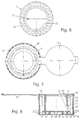
- the reference number 1 designates a cylindric body which is shown seen from above and from below in Figure 4 and 5, respectively, 2 designates a dispensing part which is shown seen from above in Figure 3, 3 is a stop ring which is seen from above in Figure 6, and 4 designates a lid part which is shown seen from above with its lid open in Figure 7.
- the cylindric body 1 has along its periphery a number of juxtaposed vertical chutes 5 which may each accommodate a number of the tablets to be dispensed piled on edge radially oriented in the body 1. If different tablets have to be dispensed in a certain sequence and this sequence has to be repeated, the number of chutes may be chosen equal to the number of dispensings in the sequence which offers the advantage that the tablets in a chute are all the same kind. This will make the filling of the dispenser more simple .
- the cylindric body 1 is provided with a central bore which at its upper end leaves the chutes 5 with a wall between the chutes and the bore but which has at its lower end an enlarged diameter, so that the radially inner wall of the chutes and part of adjacent side walls of the chutes are removed to a height corresponding to about 1.5 times the diameter of a tablet.
- a circumferential saw toothing 6 which cooperates with one or more pawls 7 on the dispensing part 2 to make the parts 1 and 2 unidirectionally stepwise rotatable relatively to each other.
- the number of teeth or steps corresponds to the number of dispensings in a sequence or a multiple thereof.
- the dispensing part 2 comprises a circular bottom plate 8 having at its periphery a circumferential upwards extending vertical wall 9 fitting over the outer periphery of the body 1. Concentric with this circumferential vertical wall there is provided another vertical cylindric wall 10 on the bottom plate 8. This cylindric wall has an outer diameter corresponding to the smaller diameter of the bore in the body part 1 allowing this cylindric wall to be inserted rotatably in this bore. When so inserted the pawls 7 will be in engagement with the internal toothing 6 in the bore.
- an opening 11 of a size allowing a tablet standing on its edge to pass.
- a radial outwardly protruding protrusion 12 with a height above the bottom plate 8 allowing a tablet standing on its edge to pass under the protrusion from the outer side of the vertical wall 10 to the inner side thereof, the protrusion fitting into the space between a lower tablet standing on its edge supported by the bottom plate 8 and another tablet piled on its edge on this lower tablet.
- the vertical wall 10 Adjacent to the opening 11 and the protrusion 12 the vertical wall 10 is provided with a partition 13 extending radially outwards from the vertical cylindric wall 10. The function of this partition 13 shall be returned to below.
- the height of the vertical wall 10 is so that this wall, when inserted in the bore of the body part 1 with the circumferential wall 9 of its bottom plate 8 fitting over the outer diameter of the body and the bottom plate 8 closing the lower ends of the chutes 5, will protrude with its upper end over the top of the body 1.
- the upper protruding part is provided with a first annular snap lock hook 14 and with a number of recesses 15.
- the stop ring 3 is an annular element having a central bore fitting over the part of the vertical wall 10 extending over the cylindric body when the wall 10 is inserted in this body.
- the central bore of the stop ring 3 is provided with protrusions 29 extending inwardly in this bore and corresponding to the recesses 15 in the upper part of the cylindric wall 10 to engage these recesses so that the stop ring 3 may be carried irrotatably on this wall 10.
- the stop ring 3 has a number of axial openings 16 corresponding to the number of chutes in the body 1, which openings in all the defined relative step positions of the body 1 and the dispensing part 2 form continuations of the chutes 5 when the stop ring is mounted at the upper end of the vertical wall 10.
- the continuations have a length smaller than the diameter of a tablet.
- the stop ring is provided with a pointer 22 at the inner side of its bore, which pointer is placed above the opening 11 and due to the unrotatable coupling between the stop ring and the vertical wall 10 will remain placed above the opening 11 when the dispensing part is rotated relatively to the body 1.
- the outer diameter of the stop ring 3 is smaller than the outer diameter of the body 1 allowing a short cylindric circumferential wall 17 on the lid part 4 to grip over the outer wall of the body 1 leaving the stop ring rotatable relatively to this body and the lid part 4, which parts are firmly coupled to each other to be rotated as a common unit relatively to a unit formed by the dispensing part 2 and the stop ring 3.
- the lid part is provided with a bore which has along its periphery a downwards extending circumferential second snap lock hook 19 which may be brought into engagement with the first snap lock hook 14 at the upper end of the vertical cylindric wall 10 of the dispensing part 2 to lock the lid part 4 to this dispensing part 2 in a way allowing rotational movement of these two parts relatively to each other.
- the lid part is further provided with a lid 18 hinged to the lid part 4 in such a way that it may be swung from a position where it covers the bore in the lid part and thereby closes the internal cylindric space inside the vertical wall 10 to a position where it admits access to this space.
- a day-ring 21 carrying an ordered sequential indication of the days in a week.
- This day ring is mounted concentrically with the lid part bore in such a way that it may be reluctantly rotated relatively to the lid part 4 possibly by the use of a tool.
- the outer surfaces of the circumferential walls 9 and 17 of the dispensing part 2 and the lid part 4, respectively, are provided with axial ribs 26 to provide a good finger grip, so that one part may be grasped by one hand, and the other part may be grasped by the other hand to rotate the two units comprising the respective parts relatively to each other.
- This rotation is made unidirectional by the pawls 7 in the dispensing part unit engaging the toothing 6 in the body part unit.
- the enlarged diameter of the lower part of the bore in the body permits this relative rotation by leaving space for the protrusion 12 and the partition 13 on the account of some of the lower parts of the chutes 5.
- the cylindric body 1 Before the tablets are filled into the dispenser, the cylindric body 1 is passed with its bore over the vertical wall 10 of the dispensing part 2, and the stop ring is mounted on the upper part of the vertical wall 10 protruding from the upper part of the cylindric body 1, the recesses 15 being so designed that the stop ring may be placed only in one rotational position in relation to the bottom part 2, namely the position where the pointer 22 is placed directly above the opening 11, which is closed by a not shown closing device which is accessible through the inner space of the vertical wall 10 to be removed when the dispensing shall begin.
- the chutes may now be filled with the tablets which have to be sequentially dispensed beginning with the chute indicated by the pointer 22. Another possibility is to fill into the chutes first the bottom layer of tablets and thereafter the overlaying layer and so on using a filling machine having a number of filling spouts corresponding to the number of chutes.
- the lid part 4 When the tablets have been filled into the chutes, the lid part 4 is placed with its circumferential wall 17 gripping over the outer cylindric wall of the body 1, and the circumferential wall 17 is made unrotatable in relation to this cylindric wall of the body 1, so that the body 1 and the lid part 4 are unrotatable in relation to each other.
- the dispenser will now appear as a tablet box which may be closed by the lid 18.
- the box When you start using the dispenser the box is opened and the day ring is rotated until the pointer 22 points at the proper day.
- the closing device is then removed, and the first tablet will roll out through the opening 11 into the inner space of the box wherefrom it may be poured out to be consumed.
- the protrusion 12 immediately above the opening 11 will prevent the overlying tablet in the chute from falling down to the position where it could roll out through the opening 11.
- the body with the chutes is moved a step forwards, the overlying tablet is moved to the opposite side of the partition, and here no protrusion is present to prevent it from falling to the bottom of the chute.
- the next tablet is dispensed when the body part 1 with its chutes 5 is rotated in relation to the dispensing part to bring the next tablet abreast of the opening 11.
- the body 1 can be rotated one step in the defined direction until the next tablet abuts the partition 13. This tablet will now be abreast of the opening 11 to be dispensed via the inner space of the box.
- the box is intended to be used in a position with its length axis about vertical and with the lid part up. If the device is tilted so that the tablets are not supported by the bottom plate, it cannot be made sure that the relative rotation is stopped by the next tablet abutting the partition 13. Therefore, the chutes are made tapering towards the bottom, so that the tablets will roll or slide to the opposite end of the chutes when the device is tilted so far that the tablets are no longer supported by the bottom plate 8. When rolling to the opposite end of the chutes, the tablets will come to a position where they are accommodated partly in the continuations of the chutes in the stop ring 3 and partly in the upper end of the chutes 5. Thereby the relative rotation of the stop ring 3 and the body 1 and consequently the relative rotation of the body 1 and the dispensing part 2 are prevented.
- a cylindric body 31 comprises a cylindric wall being on its inner surface provided with axial ribs 35 defining a number of juxtaposed chutes along the periphery of the body 31.
- the body 31 is provided with a bottom 32 having on its side facing the inner space of the body a circular rib 33 concentric with the body 31 and carrying a snap lock hook 34.
- Another circular rib 36 concentric with the first one but having a smaller diameter is provided on the same side of the bottom 32.
- a combination part combining the functions of the dispensing part 2, the stop ring 3, and the lid part 4 in Figure 1 has a cup shaped part comprising a cylindric wall 37 being at its lower end closed by a bottom plate 38 and being at its upper end provided with an annular part 40 carrying a depending cylindric skirt and a lid 39 hinged to this annular part 40.
- the outer side of the bottom plate 38 is further provided with another circular rib 43 concentric with the rib 41 but having a smaller diameter allowing it to fit into the circular rib 36 on the bottom 32 of the body 31.
- the cylindric surfaces of the ribs 36 and 43 facing each other are provided with saw tooth shaped protrusions 44 and a circular saw toothing 45, respectively, to provide a detent mechanism defining a number of possible discrete rotational positions of the body 31 and the combination part relatively to each other. This number should correspond to the number of chutes.
- This opening is dimensioned to allow a tablet standing on its edge to pass in a direction perpendicular to the axis of the tablet.
- the bottom plate 38 extends outside the cylindric wall to protrude into the chutes defined by the ribs 35.
- Adjacent to the opening in the cylindric wall 37 a radial outgoing partition 49 is provided, and above the opening a protrusion 46 is provided on the outer side of the cylindric wall 37. This protrusion 46 shall hold back an overlying tablet when a tablet is dispensed to the inner space of the cylindric wall 37 through the opening 50.
- Protruding short axial ribs 47 are provided at the upper end of the cylindric wall 37. These ribs 47 collaborate with the ribs 35 of the body 31 to define the upper end of the chutes. When a tablet is positioned in this upper end of one of the chutes, the relative rotational movement of the body and the combination part is blocked. This ensures that the dispenser is held so that it is mainly vertical with its bottom down when it is operated.
- the annular lid carrying part 40 is an integral part of the combination part and is provided by a ring shaped guide accommodating a day ring 48 rotatably in the annual part.
- This day ring may serve to close the chutes when pills have been filled into the dispenser through the top of the chutes.
- the day ring is transparent and carries the names of the days of the week in sequence. Before the dispenser is put into service, the day ring is rotated in the guide to bring a mark on the underlying body 31 abreast of the day in question. Alternatively, the names of the days may be printed at the edge of the body, one day at each chute, and a mark on the day ring may be set abreast of the day in question.
- Knurls along the periphery of the lower end of the body and on the outer side of the depending skirt provide good finger grips so that each part may be gripped to rotate the two parts relatively to each other to bring a tablet abreast of the opening 50 for dispensing into the cup formed by the combination part.
- Figure 10 shows an exploded view of another embodiment corresponding to the embodiment shown in Figure 1 and 2, but whereas the embodiment in Figure 1 and 2 shows a dispenser wherein the tablets are stored in three layers each layer containing 24 tablets, the embodiment in Figure 10 has the tablets stored in two layers each layer containing 42 tablets.
- the parts of the dispenser of Figure 10 are to some extent similar to the parts of the dispenser shown in Figure 1 and 2, only a few changes are made.
- Corresponding parts in Figure 10 and in Figure 1 and 2 are provided with the same reference numerals, only the numerals of Figure 10 has a preceding digit "1".
- the dispenser in Figure 10 comprises a cylindric body 101 having 42 chutes 105, a dispensing part 102, a stop ring 103, a lid part 104, a day ring 121, and a closing strip 150.
- the dispenser is assembled by passing a cylindric wall 110 of the dispensing part 102 into the central opening of the cylindric body 101.
- the stop ring 103 On the upper part of the cylindric wall 110 protruding through the dispensing part the stop ring 103 is positioned with protrusions 129 which extend inwardly in its bore engaging corresponding recesses 115 at the upper end of the cylindric wall 110.
- the lid part 104 is snap-locked to the cylindric wall 110 by a snap lock hook 114 at the upper end of this cylindric wall 110 snapping over the edge of a bore in the lid part.
- the lid part 104 is provided with not seen ribs corresponding to the ribs 27 in Figure 1, which ribs engage recesses 128 at the upper edge of the cylindric body 101. In this way the dispensing part 102 and the stop ring 103 constitute one part which may be rotated relative to another part constituted by the cylindric body 101 and the lid part 104.
- the relative rotation of the two parts is divided into steps defined by the cylindric body 101 being provided with recesses 151 at its lower end, one recess for each chute 105, and protrusions 152 and 153 being provided at the inner side of a circumferential vertical wall 109 at the outer edge of a bottom plate 108 of the dispensing part 102, the protrusions 152 and 153 engaging the recesses 151 of the cylindric body 101.
- the protrusions are made as two sorts of teeth, one sort 152 having two ramp shaped flanks ensuring that the tooth rests centrally in the recess 151 for safely positioning of the two parts in relation to each other, and another sort 153 having one steep flank and one ramp shaped flank ensuring that the relative rotation of the two parts is unidirectional.
- Preferably more than one tooth of each sort are provided.
- the day ring 121 has a depending skirt 156 by which it fits into the inner opening of the cylindric wall 110 on which wall is provided at not shown tooth engaging one of seven adjacent recesses 154 in the outer cylindric surface of the skirt whereby the day ring 121 may be positioned in one of seven start positions corresponding to each of the days in the week.
- the days of the week may be printed on the lid part 104 and the pointer mark may be established on the day ring.
- the day ring has inward protrusions 155 forming a finger grip by which the day ring may be rotated in the opening in the cylindric wall 110 to bring the appropriate day of the week in line with the pointer mark when the treatment is started.
- the dispensing of tablets is obtained through an opening 111 in the cylindric wall 110 when the two relative rotatable parts of the dispenser is moved stepwise in the allowed direction.
- the opening 111 is closed by a closing strip 150 which guided in a pair of guideways 157 covers the opening 111.
- the day ring 121 is rotated to bring the actual day of the week in alignment with the pointer mark and the closing strip 150 is drawn out of the guideways 157.
- the first tablet lying abreast of the opening 111 will be dispensed in the cup constituted by the dispensing part 102.
- a part of the skirt 156 is cut away to leave the opening 111 and the guideways 157 free in all the seven possible start positions of the day ring 121.
- New tablets are brought in line with the opening 111 by successive rotation of the two parts in relation to each other, and a partition and a protrusion corresponding to the partition 13 and the protrusion 12 in Figure 1 and 2 are provided to control the dispensing so that a tablet lying over the tablet abreast of the opening 111 is not dispensed immediately after the tablet abreast of the opening.
- this partition and protrusion are hidden behind the cylindric wall 110.
Landscapes
- Health & Medical Sciences (AREA)
- Engineering & Computer Science (AREA)
- Public Health (AREA)
- Life Sciences & Earth Sciences (AREA)
- Animal Behavior & Ethology (AREA)
- General Health & Medical Sciences (AREA)
- Medical Informatics (AREA)
- Veterinary Medicine (AREA)
- Mechanical Engineering (AREA)
- Closures For Containers (AREA)
- Medicinal Preparation (AREA)
- Medical Preparation Storing Or Oral Administration Devices (AREA)
- Supply Of Fluid Materials To The Packaging Location (AREA)
Claims (6)
- Spender für die aufeinanderfolgende Ausgabe von Tabletten durch eine Ausgabeöffnung in einer festgelegten Reihenfolge aus einem zylindrischen Körper (1; 31; 101), der entlang seines Umfangs eine Anzahl von benachbarten, senkrechten Schächten (5; 105) definiert, die jeweils so ausgebildet sind, daß sie eine Anzahl von hochkant gestapelten Tabletten aufnehmen, dadurch gekennzeichnet, daß die Schächte (5; 105) so ausgebildet sind, daß sie die Tabletten in radialer Richtung im Körper (1; 31; 101) ausrichten, daß ein becherförmiges Ausgabeteil (2; 102) eine Bodenplatte (8; 38; 108) und eine aufrechte zylindrische Wand (10; 37; 110) auf dieser Platte aufweist, wobei die Platte einen Stoppbereich am unteren Ende der Schächte bildet und die zylindrische Wand an ihrem unteren Ende neben der Bodenplatte einen Schlitz (11; 50; 111) aufweist, der die Ausgabeöffnung bildet, die die Passage einer hochkant gestellten Tablette von der Außenseite des Bechers in deren Innenraum ermöglicht, daß ein Vorsprung (12; 46) über dem Schlitz (11; 50) in radialer Richtung nach außen von der zylindrischen Wand in den Raum zwischen einer Tablette neben dem Schlitz und einer möglicherweise darüberliegenden Tablette im Schacht verläuft, daß eine sich radial nach außen erstreckende Wand (13; 49) neben dem Schlitz (11; 50) sich in die unteren Enden der Schächte (5; 105) erstreckt, daß ein Arretiermechanismus (6, 9; 151, 153) den Körper (1; 101) und das Ausgabeteil (2; 102) stufenweise in einer einzigen Richtung relativ zueinander drehbar macht, wobei die Anzahl der Stufen der Anzahl der Schächte (5; 105) entspricht und die Drehrichtung so beschaffen ist, daß die Schächte (5; 105) von einer Position neben dem Schlitz (11; 50; 111) in Richtung zur radial sich erstreckenden Wand (13; 49) bewegt werden, so daß die Drehung gestoppt wird, wenn eine Tablette im unteren Ende des Schachts neben dem Schlitz an der sich radial erstreckenden Wand (13; 49) anstößt, daß ein ringförmiges Deckelteil (4; 104) nach oben das obere Ende der Schächte (5; 105) verschließt und entweder am Körper (1; 31; 101) oder am Ausgabeteil (2; 102) befestigt ist, um diesem Teil in seiner Drehrichtung relativ zum anderen Teil zu folgen, und daß die zylindrische Wand (10; 37; 110) des Ausgabeteils (2; 102) am oberen Ende einen Stoppring (3; 10) trägt, der entlang seines Umfangs mit Wänden (47) versehen ist, die bei jeder der Stufenpositionen des Ausgabeteils Fortsetzungen der Schächte bilden, wobei die Stoppringe (3; 103) am Ausgabeteil (2; 102) befestigt sind, um diesen Teil relativ zum Körper (1; 101) zu drehen.
- Spender nach Anspruch 1, dadurch gekennzeichnet, daß die Schächte konisch ausgebildet und an der Oberseite am breitesten sind.
- Spender nach Anspruch 1 oder 2, dadurch gekennzeichnet daß das Deckelteil einen Tageszählring (21; 48) tragt, der konzentrisch mit dem Deckelteil (4; 104) verläuft und relativ zu diesem Deckelteil gedreht werden kann.
- Spender nach Anspruch 3, dadurch gekennzeichnet, daß ein Zeiger (22) an dem relativ zum Körper (1; 101) drehbaren Ausgabeteil (2; 102) für eine Anzeige am Tageszählring (21; 48), befestige ist.
- Spender nach Anspruch 3 oder 4, dadurch gekennzeichnet, daß das Deckelteil (4; 104) einen angelenkten Deckel (18; 39) trägt, der zum Abdecken des Tageszählrings (21; 48) und der Öffnung eines Bechers, der durch die zylindrische Wand (10; 37; 110) und die Bodenplatte (8; 38; 108) das Ausgabeteils (2; 102) gebildet wird, geschlossen werden kann.
- Spender nach einem der vorstehenden Ansprüche, dadurch gekennzeichnet, daß eine entfernbare Sperrvorrichtung (150) an der Innenseite der zylindrischen Wand (10; 37; 110) den Schlitz (11; 50; 111) bedeckt.
Applications Claiming Priority (3)
| Application Number | Priority Date | Filing Date | Title |
|---|---|---|---|
| DK1516/92 | 1992-12-18 | ||
| DK151692 | 1992-12-18 | ||
| PCT/DK1993/000424 WO1994014681A1 (en) | 1992-12-18 | 1993-12-17 | Dispenser for consecutive dispensing of tablets |
Publications (2)
| Publication Number | Publication Date |
|---|---|
| EP0673339A1 EP0673339A1 (de) | 1995-09-27 |
| EP0673339B1 true EP0673339B1 (de) | 1997-12-03 |
Family
ID=8105654
Family Applications (1)
| Application Number | Title | Priority Date | Filing Date |
|---|---|---|---|
| EP94903740A Expired - Lifetime EP0673339B1 (de) | 1992-12-18 | 1993-12-17 | Spender zum nachfolgenden ausgeben von tabletten |
Country Status (7)
| Country | Link |
|---|---|
| US (1) | US5630525A (de) |
| EP (1) | EP0673339B1 (de) |
| JP (1) | JPH08504713A (de) |
| AT (1) | ATE160754T1 (de) |
| AU (1) | AU5808694A (de) |
| DE (1) | DE69315592T2 (de) |
| WO (1) | WO1994014681A1 (de) |
Families Citing this family (4)
| Publication number | Priority date | Publication date | Assignee | Title |
|---|---|---|---|---|
| US6039208A (en) * | 1994-07-29 | 2000-03-21 | Ortho Pharmaceutical Corporation | Variable day start tablet dispenser |
| NL1001031C1 (nl) * | 1995-08-23 | 1997-02-25 | Npk Ind Design B V | Inrichting voor het afgeven van pillen uit een blisterverpakking. |
| FI117689B (fi) * | 2002-08-21 | 2007-01-31 | Addoz Oy | Laite pillerin tai kapselin muotoisten lääkkeiden jakelemiseksi haluttuina annoksina |
| GB2412363C (en) * | 2003-02-05 | 2006-08-03 | Martin John Tedham | Dispenser |
Family Cites Families (9)
| Publication number | Priority date | Publication date | Assignee | Title |
|---|---|---|---|---|
| US3095085A (en) * | 1959-10-15 | 1963-06-25 | Meijer Leo | Pocket containers for the selective dispensing of tablets |
| US3527383A (en) * | 1968-10-17 | 1970-09-08 | Adolph W Borsum | Apparatus for dispensing pills or the like |
| US3604559A (en) * | 1969-10-15 | 1971-09-14 | Lilly Co Eli | Multilayer dispenser for pills |
| GB1594132A (en) * | 1977-08-15 | 1981-07-30 | Johnsen Jorgensen Plastics Ltd | Dispensing containers |
| US4667845A (en) * | 1985-06-21 | 1987-05-26 | Ortho Pharmaceutical Corporation | Tablet dispenser |
| US4807757A (en) * | 1987-08-04 | 1989-02-28 | Rappaport Lisa N | Pill dispenser providing sequential dispensing means and automatic incremental dispensing control |
| US5127543A (en) * | 1990-09-04 | 1992-07-07 | Cheskel Meisels | Device for reducing cigarette consumption |
| DE4035662A1 (de) * | 1990-11-09 | 1992-05-14 | Pfeiffer Erich Gmbh & Co Kg | Ausgabespeicher fuer kleinteile, insbesondere pharmazeutische pillen |
| US5152422A (en) * | 1990-12-17 | 1992-10-06 | Springer Reinhold A | Medication dispenser |
-
1993
- 1993-12-17 JP JP6514696A patent/JPH08504713A/ja active Pending
- 1993-12-17 WO PCT/DK1993/000424 patent/WO1994014681A1/en not_active Ceased
- 1993-12-17 EP EP94903740A patent/EP0673339B1/de not_active Expired - Lifetime
- 1993-12-17 US US08/464,751 patent/US5630525A/en not_active Expired - Fee Related
- 1993-12-17 DE DE69315592T patent/DE69315592T2/de not_active Expired - Fee Related
- 1993-12-17 AT AT94903740T patent/ATE160754T1/de not_active IP Right Cessation
- 1993-12-17 AU AU58086/94A patent/AU5808694A/en not_active Abandoned
Also Published As
| Publication number | Publication date |
|---|---|
| ATE160754T1 (de) | 1997-12-15 |
| DE69315592T2 (de) | 1998-06-18 |
| US5630525A (en) | 1997-05-20 |
| WO1994014681A1 (en) | 1994-07-07 |
| JPH08504713A (ja) | 1996-05-21 |
| DE69315592D1 (de) | 1998-01-15 |
| AU5808694A (en) | 1994-07-19 |
| EP0673339A1 (de) | 1995-09-27 |
Similar Documents
| Publication | Publication Date | Title |
|---|---|---|
| US5791515A (en) | One at a time pill/medication dispenser | |
| US4646936A (en) | Pill dispenser | |
| US4572376A (en) | Dial pill box | |
| US7128213B2 (en) | Convertible pill container | |
| US4334617A (en) | Medication dispenser | |
| US5520307A (en) | Dispensing top for pill case | |
| US4984709A (en) | Non-reversing tablet dispenser with counter | |
| US5322166A (en) | Pill storage and dispensing container | |
| US4583667A (en) | Partitioning dispensing container | |
| US4749093A (en) | Child-resistant medication reminder | |
| CA1263349A (en) | Tablet dispenser | |
| US6098835A (en) | Child resistant pill rotating disk dispenser | |
| US4127190A (en) | Dispenser for dispensing pills or tablets in a predetermined order | |
| US6126010A (en) | Collapsible cup and pill organizer unit | |
| US4381059A (en) | Puzzle-locking container and method for storing and dispensing articles | |
| NZ248005A (en) | Tablet dispenser with periodicity indicator and tablet package in circular array with push lever operated from outside of the dispenser to effect stepwise rotation of package bottom for single tablet dispensing | |
| US11873146B1 (en) | Child safety device for medication dispenser | |
| US11767150B2 (en) | Pill container and methods | |
| US20050029154A1 (en) | One dose at-a-time pill dispenser and container having same | |
| US9815611B2 (en) | Device and method for singularized dispensing of solid portions | |
| US4117952A (en) | Capsule dispenser having chambers rotatable relative to a dispensing outlet | |
| US5921395A (en) | Dispenser with safety locks | |
| US20250333216A1 (en) | Container with dispenser lid | |
| US5630525A (en) | Dispenser for consecutive dispensing of tablets | |
| EP0554953B1 (de) | Taschenträger zum Spenden von Produkten in genaue Menge |
Legal Events
| Date | Code | Title | Description |
|---|---|---|---|
| PUAI | Public reference made under article 153(3) epc to a published international application that has entered the european phase |
Free format text: ORIGINAL CODE: 0009012 |
|
| 17P | Request for examination filed |
Effective date: 19950718 |
|
| AK | Designated contracting states |
Kind code of ref document: A1 Designated state(s): AT BE CH DE DK ES FR GB GR IE IT LI LU NL PT SE |
|
| 17Q | First examination report despatched |
Effective date: 19960705 |
|
| GRAG | Despatch of communication of intention to grant |
Free format text: ORIGINAL CODE: EPIDOS AGRA |
|
| GRAH | Despatch of communication of intention to grant a patent |
Free format text: ORIGINAL CODE: EPIDOS IGRA |
|
| GRAH | Despatch of communication of intention to grant a patent |
Free format text: ORIGINAL CODE: EPIDOS IGRA |
|
| GRAA | (expected) grant |
Free format text: ORIGINAL CODE: 0009210 |
|
| AK | Designated contracting states |
Kind code of ref document: B1 Designated state(s): AT BE CH DE DK ES FR GB GR IE IT LI LU NL PT SE |
|
| PG25 | Lapsed in a contracting state [announced via postgrant information from national office to epo] |
Ref country code: NL Free format text: LAPSE BECAUSE OF FAILURE TO SUBMIT A TRANSLATION OF THE DESCRIPTION OR TO PAY THE FEE WITHIN THE PRESCRIBED TIME-LIMIT Effective date: 19971203 Ref country code: IT Free format text: LAPSE BECAUSE OF FAILURE TO SUBMIT A TRANSLATION OF THE DESCRIPTION OR TO PAY THE FEE WITHIN THE PRESCRIBED TIME-LIMIT;WARNING: LAPSES OF ITALIAN PATENTS WITH EFFECTIVE DATE BEFORE 2007 MAY HAVE OCCURRED AT ANY TIME BEFORE 2007. THE CORRECT EFFECTIVE DATE MAY BE DIFFERENT FROM THE ONE RECORDED. Effective date: 19971203 Ref country code: GR Free format text: LAPSE BECAUSE OF FAILURE TO SUBMIT A TRANSLATION OF THE DESCRIPTION OR TO PAY THE FEE WITHIN THE PRESCRIBED TIME-LIMIT Effective date: 19971203 Ref country code: ES Free format text: THE PATENT HAS BEEN ANNULLED BY A DECISION OF A NATIONAL AUTHORITY Effective date: 19971203 Ref country code: DK Free format text: LAPSE BECAUSE OF NON-PAYMENT OF DUE FEES Effective date: 19971203 |
|
| REF | Corresponds to: |
Ref document number: 160754 Country of ref document: AT Date of ref document: 19971215 Kind code of ref document: T |
|
| REG | Reference to a national code |
Ref country code: CH Ref legal event code: EP |
|
| PG25 | Lapsed in a contracting state [announced via postgrant information from national office to epo] |
Ref country code: LU Free format text: LAPSE BECAUSE OF NON-PAYMENT OF DUE FEES Effective date: 19971217 |
|
| REF | Corresponds to: |
Ref document number: 69315592 Country of ref document: DE Date of ref document: 19980115 |
|
| PG25 | Lapsed in a contracting state [announced via postgrant information from national office to epo] |
Ref country code: IE Free format text: LAPSE BECAUSE OF NON-PAYMENT OF DUE FEES Effective date: 19980203 |
|
| REG | Reference to a national code |
Ref country code: CH Ref legal event code: NV Representative=s name: R. A. EGLI & CO. PATENTANWAELTE |
|
| PG25 | Lapsed in a contracting state [announced via postgrant information from national office to epo] |
Ref country code: SE Free format text: LAPSE BECAUSE OF FAILURE TO SUBMIT A TRANSLATION OF THE DESCRIPTION OR TO PAY THE FEE WITHIN THE PRESCRIBED TIME-LIMIT Effective date: 19980303 Ref country code: PT Free format text: LAPSE BECAUSE OF FAILURE TO SUBMIT A TRANSLATION OF THE DESCRIPTION OR TO PAY THE FEE WITHIN THE PRESCRIBED TIME-LIMIT Effective date: 19980303 |
|
| ET | Fr: translation filed | ||
| NLV1 | Nl: lapsed or annulled due to failure to fulfill the requirements of art. 29p and 29m of the patents act | ||
| PLBE | No opposition filed within time limit |
Free format text: ORIGINAL CODE: 0009261 |
|
| STAA | Information on the status of an ep patent application or granted ep patent |
Free format text: STATUS: NO OPPOSITION FILED WITHIN TIME LIMIT |
|
| 26N | No opposition filed | ||
| REG | Reference to a national code |
Ref country code: GB Ref legal event code: IF02 |
|
| PGFP | Annual fee paid to national office [announced via postgrant information from national office to epo] |
Ref country code: FR Payment date: 20021210 Year of fee payment: 10 |
|
| PGFP | Annual fee paid to national office [announced via postgrant information from national office to epo] |
Ref country code: GB Payment date: 20021211 Year of fee payment: 10 Ref country code: AT Payment date: 20021211 Year of fee payment: 10 |
|
| PGFP | Annual fee paid to national office [announced via postgrant information from national office to epo] |
Ref country code: DE Payment date: 20021219 Year of fee payment: 10 |
|
| PGFP | Annual fee paid to national office [announced via postgrant information from national office to epo] |
Ref country code: CH Payment date: 20030108 Year of fee payment: 10 |
|
| PGFP | Annual fee paid to national office [announced via postgrant information from national office to epo] |
Ref country code: BE Payment date: 20030218 Year of fee payment: 10 |
|
| PG25 | Lapsed in a contracting state [announced via postgrant information from national office to epo] |
Ref country code: GB Free format text: LAPSE BECAUSE OF NON-PAYMENT OF DUE FEES Effective date: 20031217 Ref country code: AT Free format text: LAPSE BECAUSE OF NON-PAYMENT OF DUE FEES Effective date: 20031217 |
|
| PG25 | Lapsed in a contracting state [announced via postgrant information from national office to epo] |
Ref country code: LI Free format text: LAPSE BECAUSE OF NON-PAYMENT OF DUE FEES Effective date: 20031231 Ref country code: CH Free format text: LAPSE BECAUSE OF NON-PAYMENT OF DUE FEES Effective date: 20031231 Ref country code: BE Free format text: LAPSE BECAUSE OF NON-PAYMENT OF DUE FEES Effective date: 20031231 |
|
| BERE | Be: lapsed |
Owner name: *NOVO NORDISK A/S Effective date: 20031231 |
|
| PG25 | Lapsed in a contracting state [announced via postgrant information from national office to epo] |
Ref country code: DE Free format text: LAPSE BECAUSE OF NON-PAYMENT OF DUE FEES Effective date: 20040701 |
|
| GBPC | Gb: european patent ceased through non-payment of renewal fee |
Effective date: 20031217 |
|
| REG | Reference to a national code |
Ref country code: CH Ref legal event code: PL |
|
| PG25 | Lapsed in a contracting state [announced via postgrant information from national office to epo] |
Ref country code: FR Free format text: LAPSE BECAUSE OF NON-PAYMENT OF DUE FEES Effective date: 20040831 |
|
| REG | Reference to a national code |
Ref country code: FR Ref legal event code: ST |