EP0673330B1 - An integrated environmental control system for a helicopter - Google Patents
An integrated environmental control system for a helicopter Download PDFInfo
- Publication number
- EP0673330B1 EP0673330B1 EP94904435A EP94904435A EP0673330B1 EP 0673330 B1 EP0673330 B1 EP 0673330B1 EP 94904435 A EP94904435 A EP 94904435A EP 94904435 A EP94904435 A EP 94904435A EP 0673330 B1 EP0673330 B1 EP 0673330B1
- Authority
- EP
- European Patent Office
- Prior art keywords
- airflow
- super
- dry
- operative
- duct
- Prior art date
- Legal status (The legal status is an assumption and is not a legal conclusion. Google has not performed a legal analysis and makes no representation as to the accuracy of the status listed.)
- Expired - Lifetime
Links
- 230000007613 environmental effect Effects 0.000 title claims abstract description 38
- 238000001816 cooling Methods 0.000 claims abstract description 81
- 239000000356 contaminant Substances 0.000 claims abstract description 21
- 230000001172 regenerating effect Effects 0.000 claims abstract description 15
- 239000003507 refrigerant Substances 0.000 claims abstract description 13
- 238000005202 decontamination Methods 0.000 claims abstract description 12
- 230000003588 decontaminative effect Effects 0.000 claims abstract description 12
- 230000008595 infiltration Effects 0.000 claims abstract description 10
- 238000001764 infiltration Methods 0.000 claims abstract description 10
- 239000000126 substance Substances 0.000 claims abstract description 9
- 238000010926 purge Methods 0.000 claims description 26
- 238000012546 transfer Methods 0.000 claims description 11
- 238000011144 upstream manufacturing Methods 0.000 claims description 7
- 238000001914 filtration Methods 0.000 claims description 5
- 238000012354 overpressurization Methods 0.000 claims description 5
- 230000005465 channeling Effects 0.000 claims description 4
- 238000010438 heat treatment Methods 0.000 claims description 3
- 230000037361 pathway Effects 0.000 claims description 3
- 239000003570 air Substances 0.000 description 12
- ZZYSLNWGKKDOML-UHFFFAOYSA-N tebufenpyrad Chemical compound CCC1=NN(C)C(C(=O)NCC=2C=CC(=CC=2)C(C)(C)C)=C1Cl ZZYSLNWGKKDOML-UHFFFAOYSA-N 0.000 description 7
- OKTJSMMVPCPJKN-UHFFFAOYSA-N Carbon Chemical compound [C] OKTJSMMVPCPJKN-UHFFFAOYSA-N 0.000 description 6
- 229910052799 carbon Inorganic materials 0.000 description 6
- 238000013461 design Methods 0.000 description 5
- 239000012080 ambient air Substances 0.000 description 4
- 230000001143 conditioned effect Effects 0.000 description 4
- 238000007710 freezing Methods 0.000 description 4
- 230000008014 freezing Effects 0.000 description 4
- 238000009833 condensation Methods 0.000 description 3
- 230000005494 condensation Effects 0.000 description 3
- 230000003750 conditioning effect Effects 0.000 description 3
- 230000000694 effects Effects 0.000 description 3
- 230000001105 regulatory effect Effects 0.000 description 3
- 230000003292 diminished effect Effects 0.000 description 2
- 238000005516 engineering process Methods 0.000 description 2
- 239000007788 liquid Substances 0.000 description 2
- 238000000034 method Methods 0.000 description 2
- 230000008569 process Effects 0.000 description 2
- RZVHIXYEVGDQDX-UHFFFAOYSA-N 9,10-anthraquinone Chemical compound C1=CC=C2C(=O)C3=CC=CC=C3C(=O)C2=C1 RZVHIXYEVGDQDX-UHFFFAOYSA-N 0.000 description 1
- 238000010586 diagram Methods 0.000 description 1
- 231100001261 hazardous Toxicity 0.000 description 1
- 238000002156 mixing Methods 0.000 description 1
- 230000004048 modification Effects 0.000 description 1
- 238000012986 modification Methods 0.000 description 1
- 238000012545 processing Methods 0.000 description 1
- 230000003134 recirculating effect Effects 0.000 description 1
- 230000009467 reduction Effects 0.000 description 1
- 230000008929 regeneration Effects 0.000 description 1
- 238000011069 regeneration method Methods 0.000 description 1
- 230000004044 response Effects 0.000 description 1
- 229920006395 saturated elastomer Polymers 0.000 description 1
- 238000001179 sorption measurement Methods 0.000 description 1
- 230000000153 supplemental effect Effects 0.000 description 1
Images

Classifications
-
- B—PERFORMING OPERATIONS; TRANSPORTING
- B64—AIRCRAFT; AVIATION; COSMONAUTICS
- B64D—EQUIPMENT FOR FITTING IN OR TO AIRCRAFT; FLIGHT SUITS; PARACHUTES; ARRANGEMENT OR MOUNTING OF POWER PLANTS OR PROPULSION TRANSMISSIONS IN AIRCRAFT
- B64D13/00—Arrangements or adaptations of air-treatment apparatus for aircraft crew or passengers, or freight space
- B64D13/02—Arrangements or adaptations of air-treatment apparatus for aircraft crew or passengers, or freight space the air being pressurised
- B64D13/04—Automatic control of pressure
-
- B—PERFORMING OPERATIONS; TRANSPORTING
- B64—AIRCRAFT; AVIATION; COSMONAUTICS
- B64D—EQUIPMENT FOR FITTING IN OR TO AIRCRAFT; FLIGHT SUITS; PARACHUTES; ARRANGEMENT OR MOUNTING OF POWER PLANTS OR PROPULSION TRANSMISSIONS IN AIRCRAFT
- B64D13/00—Arrangements or adaptations of air-treatment apparatus for aircraft crew or passengers, or freight space
-
- B—PERFORMING OPERATIONS; TRANSPORTING
- B64—AIRCRAFT; AVIATION; COSMONAUTICS
- B64D—EQUIPMENT FOR FITTING IN OR TO AIRCRAFT; FLIGHT SUITS; PARACHUTES; ARRANGEMENT OR MOUNTING OF POWER PLANTS OR PROPULSION TRANSMISSIONS IN AIRCRAFT
- B64D13/00—Arrangements or adaptations of air-treatment apparatus for aircraft crew or passengers, or freight space
- B64D13/06—Arrangements or adaptations of air-treatment apparatus for aircraft crew or passengers, or freight space the air being conditioned
- B64D13/08—Arrangements or adaptations of air-treatment apparatus for aircraft crew or passengers, or freight space the air being conditioned the air being heated or cooled
-
- B—PERFORMING OPERATIONS; TRANSPORTING
- B64—AIRCRAFT; AVIATION; COSMONAUTICS
- B64D—EQUIPMENT FOR FITTING IN OR TO AIRCRAFT; FLIGHT SUITS; PARACHUTES; ARRANGEMENT OR MOUNTING OF POWER PLANTS OR PROPULSION TRANSMISSIONS IN AIRCRAFT
- B64D13/00—Arrangements or adaptations of air-treatment apparatus for aircraft crew or passengers, or freight space
- B64D13/06—Arrangements or adaptations of air-treatment apparatus for aircraft crew or passengers, or freight space the air being conditioned
- B64D2013/0603—Environmental Control Systems
- B64D2013/0614—Environmental Control Systems with subsystems for cooling avionics
-
- B—PERFORMING OPERATIONS; TRANSPORTING
- B64—AIRCRAFT; AVIATION; COSMONAUTICS
- B64D—EQUIPMENT FOR FITTING IN OR TO AIRCRAFT; FLIGHT SUITS; PARACHUTES; ARRANGEMENT OR MOUNTING OF POWER PLANTS OR PROPULSION TRANSMISSIONS IN AIRCRAFT
- B64D13/00—Arrangements or adaptations of air-treatment apparatus for aircraft crew or passengers, or freight space
- B64D13/06—Arrangements or adaptations of air-treatment apparatus for aircraft crew or passengers, or freight space the air being conditioned
- B64D2013/0603—Environmental Control Systems
- B64D2013/0651—Environmental Control Systems comprising filters, e.g. dust filters
-
- B—PERFORMING OPERATIONS; TRANSPORTING
- B64—AIRCRAFT; AVIATION; COSMONAUTICS
- B64D—EQUIPMENT FOR FITTING IN OR TO AIRCRAFT; FLIGHT SUITS; PARACHUTES; ARRANGEMENT OR MOUNTING OF POWER PLANTS OR PROPULSION TRANSMISSIONS IN AIRCRAFT
- B64D13/00—Arrangements or adaptations of air-treatment apparatus for aircraft crew or passengers, or freight space
- B64D13/06—Arrangements or adaptations of air-treatment apparatus for aircraft crew or passengers, or freight space the air being conditioned
- B64D2013/0603—Environmental Control Systems
- B64D2013/0662—Environmental Control Systems with humidity control
-
- F—MECHANICAL ENGINEERING; LIGHTING; HEATING; WEAPONS; BLASTING
- F25—REFRIGERATION OR COOLING; COMBINED HEATING AND REFRIGERATION SYSTEMS; HEAT PUMP SYSTEMS; MANUFACTURE OR STORAGE OF ICE; LIQUEFACTION SOLIDIFICATION OF GASES
- F25B—REFRIGERATION MACHINES, PLANTS OR SYSTEMS; COMBINED HEATING AND REFRIGERATION SYSTEMS; HEAT PUMP SYSTEMS
- F25B9/00—Compression machines, plants or systems, in which the refrigerant is air or other gas of low boiling point
- F25B9/002—Compression machines, plants or systems, in which the refrigerant is air or other gas of low boiling point characterised by the refrigerant
- F25B9/004—Compression machines, plants or systems, in which the refrigerant is air or other gas of low boiling point characterised by the refrigerant the refrigerant being air
-
- Y—GENERAL TAGGING OF NEW TECHNOLOGICAL DEVELOPMENTS; GENERAL TAGGING OF CROSS-SECTIONAL TECHNOLOGIES SPANNING OVER SEVERAL SECTIONS OF THE IPC; TECHNICAL SUBJECTS COVERED BY FORMER USPC CROSS-REFERENCE ART COLLECTIONS [XRACs] AND DIGESTS
- Y02—TECHNOLOGIES OR APPLICATIONS FOR MITIGATION OR ADAPTATION AGAINST CLIMATE CHANGE
- Y02T—CLIMATE CHANGE MITIGATION TECHNOLOGIES RELATED TO TRANSPORTATION
- Y02T50/00—Aeronautics or air transport
- Y02T50/40—Weight reduction
-
- Y—GENERAL TAGGING OF NEW TECHNOLOGICAL DEVELOPMENTS; GENERAL TAGGING OF CROSS-SECTIONAL TECHNOLOGIES SPANNING OVER SEVERAL SECTIONS OF THE IPC; TECHNICAL SUBJECTS COVERED BY FORMER USPC CROSS-REFERENCE ART COLLECTIONS [XRACs] AND DIGESTS
- Y02—TECHNOLOGIES OR APPLICATIONS FOR MITIGATION OR ADAPTATION AGAINST CLIMATE CHANGE
- Y02T—CLIMATE CHANGE MITIGATION TECHNOLOGIES RELATED TO TRANSPORTATION
- Y02T50/00—Aeronautics or air transport
- Y02T50/50—On board measures aiming to increase energy efficiency
-
- Y—GENERAL TAGGING OF NEW TECHNOLOGICAL DEVELOPMENTS; GENERAL TAGGING OF CROSS-SECTIONAL TECHNOLOGIES SPANNING OVER SEVERAL SECTIONS OF THE IPC; TECHNICAL SUBJECTS COVERED BY FORMER USPC CROSS-REFERENCE ART COLLECTIONS [XRACs] AND DIGESTS
- Y10—TECHNICAL SUBJECTS COVERED BY FORMER USPC
- Y10S—TECHNICAL SUBJECTS COVERED BY FORMER USPC CROSS-REFERENCE ART COLLECTIONS [XRACs] AND DIGESTS
- Y10S62/00—Refrigeration
- Y10S62/05—Aircraft cooling
Definitions
- the present invention is directed to environmental control systems for helicopters, and more particularly, to an integrated environmental control system that combines an environmental control system and a nuclear/biological/chemical life support system in a unitary, compact, lightweight airflow processing system that provides super-cooled, super-dry, decontaminated airflow, in seriatim, to mission equipment package bays and the cockpit of a helicopter for cooling of avionics/electronic modules and crew comfort.
- helicopters are high technology aircraft that incorporate a plethora of avionics/electronic modules that markedly improve the overall capabilities of the helicopter, enhance the flight operations thereof, and/or reduce the pilot/co-pilot workloads.
- operation of these modules generates a large quantity of thermal energy that must be effectively dissipated, i.e., by cooling to ensure continuous, reliable operation of the avionics/electronic modules.
- helicopters typically include an environmental control system (ECS) that provides a temperature/pressure regulated airflow for cooling of the avionics/electronic modules.
- ECS environmental control system
- the regulated airflow is generally further utilized for crew comfort, and may be used for over pressurizing the helicopter to preclude contaminant infiltration.
- NBC LSS nuclear/biological/chemical life support system
- NBC particulates/contaminants may be effectively removed utilizing a high pressure carbon filter
- such filters do not remove a sufficient amount of the moisture content of the cooled, decontaminated airflow to facilitate effective utilization of such airflow.
- the cooled, decontaminated airflow exiting the ECS portion of the integrated environmental control system must be channeled in parallel paths to the aircraft cockpit and avionics/electronic modules to achieve the desired cooling effects due to the moisture content thereof. If such cooled, decontaminated airflow is directly utilized for cooling of avionics/electronic modules, there is a risk that such airflow will induce moisture condensation and/or freezing in the avionics/electronic modules.
- the cooled, decontaminated airflow is further conditioned, e.g., by mixing warmer airflow with such airflow or utilizing a heat exchange apparatus to raise the temperature of the airflow slightly above freezing (32°F), prior to being utilized to cool the avionics/electronic modules.
- the need to effect such downstream conditioning of the system airflow severely limits the overall efficiency of the integrated environmental control system.
- the airflow cooling capacity of the ECS portion of the integrated environmental control system is not effectively utilized in light of the requirement for downstream conditioning, i.e., heating, of the cooling airflow.
- the conditioned cooling airflow has a limited thermal cooling capacity that is essentially exhausted in cooling the avionics/electronic modules in mission equipment package bays.
- the integrated environmental control system requires a second cooling airflow for the cockpit.
- the cooled, decontaminated airflow channeled directly to the cockpit has a temperature that is generally too low for cockpit usage.
- the cockpit cooling airflow is further conditioned by a heat exchange apparatus so as to raise the cockpit cooling airflow to a temperature that provides a comfortable cockpit environment.
- PSA pressure swing adsorption
- U.S. Patent No. 4,769,051 A representative example of such a system, is illustrated in U.S. Patent No. 4,769,051.
- the PSA apparatus described in the '051 patent is operative not only to remove NBC particulates/contaminants from the generated airflow, but also to remove substantially all the moisture content thereof. That is, the PSA apparatus provides a super-dry, decontaminated airflow.
- the integrated environmental control system described in the '051 patent is a closed, two loop cooling system similar in structure and function to the closed, two loop cooling systems employed in nuclear reactors.
- a closed, two loop cooling system is not an optimum configuration for helicopter applications, requiring ancillary components and airflow ducting to effectuate the desired cooling function, which increases overall system weight, while concomitantly having a lower overall operating efficiency.
- the cooled, super-dry, decontaminated airflow generated by the PSA apparatus and the air cycle machine described in the '051 patent is channeled through a first loop that passes through a load heat exchanger.
- the cooled, super-dry decontaminated airflow in the first loop is therefore utilized to indirectly cool the airflow of the second loop for subsequent cooling of the closed environment.
- the integrated environmental control system should provide a super-cooled, super-dry, decontaminated airflow and should be design optimized to fully utilize the thermal cooling capacity of the super-cooled, super-dry, decontaminated airflow for direct cooling of helicopter avionics/electronic modules and crew comfort.
- One object of the present invention is to provide a unitary, compact, lightweight integrated environmental control (IEC) system for a helicopter comprising an environmental control system and a nuclear/biological/chemical life support system that has an improved operating efficiency.
- IEC integrated environmental control
- Another object of the present invention is to provide an IEC system for a helicopter that provides a super-cooled, super-dry, decontaminated airflow for cooling avionics/electronic modules and crew comfort.
- Still another object of the present invention is to provide an IEC system that has an airflow distribution network that channels the super-cooled, super-dry, decontaminated airflow in seriatim directly to mission equipment package bays and the cockpit for direct cooling of the avionics/electronic modules thereof and for crew comfort.
- an integrated environment control (IEC) system for a helicopter having a plurality of mission equipment package bays containing electronic modules and a cockpit that includes electronic modules comprising a refrigerant subsystem that is operative to provide a highly compressed airflow, a decontamination subsystem that is operative to decontaminate and demoisturize the highly compressed airflow from the refrigerant subsystem to provide a super-dry, decontaminated airflow, the refrigerant subsystem being further operative to super cool the super-dry, decontaminated airflow from the decontamination subsystem to provide a super-cooled, super-dry, decontaminated airflow, and an airflow distribution network.
- IEC integrated environment control
- the IEC system is characterized in that the airflow distribution network is operative to channel the super-cooled, super-dry, decontaminated airflow, in seriatim, directly to at least one of the plurality of mission equipment package bays and the cockpit for cooling the electronic modules thereof and crew comfort.
- the IEC system may also include ducting means downstream of the at least one mission equipment package bay for diverting cooled, super-dry, decontaminated airflow discharged from the at least one mission equipment bay to another of the plurality of mission equipment bays for cooling the electronic modules thereof.
- the ducting means may be further operative to channel the cooled, super-dry, decontaminated airflow to the at least one mission equipment bay for overpressurization thereof to prevent contaminant infiltration thereof.
- the IEC system may further include an auxiliary heat exchange subsystem disposed in operative combination with the airflow distribution network upstream of the cockpit for heating the cooled, super-dry, decontaminated airflow discharged from the at least one mission equipment package bay for crew comfort during cold weather flight operations.
- the IEC system may in addition include an ambient back-up subsystem fluidically interconnected to the airflow distribution network for providing emergency cooling airflow to the at least one mission equipment package bay and the cockpit for cooling the electronic modules thereof and crew comfort.
- an integrated environment control (IEC) system for a helicopter having left, right, and mid mission equipment package bays containing electronic modules and a cockpit that includes electronic modules that comprises an air cycle machine having a compressor stage and a turbine stage, the compressor stage being operative to provide a highly compressed airflow, a means for providing a purge airflow, a regenerative heat exchange apparatus operative to transfer thermal energy from the highly compressed airflow to the purge airflow, a pressure swing adsorber, nuclear/biological/chemical filtration apparatus that includes a high efficiency particulate air filter and first and second alternatively operative regenerative beds that are operative in combination to decontaminate and demoisturize the highly compressed airflow to provide a super-dry, decontaminated airflow, the second and first regenerative beds being alternatively purged of contaminants by the purge airflow, the turbine stage of the air cycle machine being operative to super cool the super-dry, decontaminated airflow to provide a super-cooled, super-dry, decontaminated airflow and an airflow distribution network.
- IEC
- the IEC system is characterized in that the airflow distribution network is operative to channel the super-cooled, super-dry, decontaminated airflow, in seriatim, directly to the left and right mission equipment package bays and the cockpit for cooling the electronic modules thereof and crew comfort.
- the airflow distribution network comprises a first distribution duct for channeling the super-cooled, super-dry, decontaminated airflow directly to the left and right mission equipment package bays, upstream parallel distribution ducts fluidically interconnected to the first distribution duct for directing the super-cooled, super-dry, decontaminated airflow directly to the left and right mission equipment package bays, respectively, for cooling the electronic modules thereof, downstream distribution ducts for receiving cooled, super-dry, decontaminated airflow discharged from the left and right mission equipment package bays, respectively, and a common distribution duct fluidically interconnected to the downstream parallel distribution ducts for channeling the cooled, super-dry, decontaminated airflow to the cockpit for cooling the electronic modules therein and crew comfort.
- the airflow distribution network of the other embodiment may also include a diverter duct fluidically interconnected to the common distribution duct and a first subdistribution duct fluidically interconnected to the diverter duct and to the mid mission equipment package bay, the diverter duct and the first subdistribution duct in combination being operative to channel a first portion of the cooled, super-dry, decontaminated airflow from the common distribution duct to the mid mission equipment package bay for cooling the electronic modules thereof.
- the airflow distribution network may also include a second subdistribution duct fluidically interconnected to the diverter duct and the left and right mission equipment package bays, the diverter duct and the second subdistribution duct being operative in combination to channel a second portion of the cooled, super-dry, decontaminated airflow from the common distribution duct to the left and right mission equipment package bays for overpressurization thereof to preclude contaminant infiltration thereof.
- the other embodiment of the IEC system may further include a subsystem power unit fluidically interconnected to the compressor stage of the air cycle machine and operative to provide compressed airflow to the compressor stage during helicopter operations.
- This embodiment of the IEC system may also include left and right coldplates disposed in the left and right mission equipment package bays, respectively, which are fluidically interconnected respectively to the upstream and downstream parallel distribution ducts, and wherein the electronic modules of the left and right mission equipment package bays are physically attached to the left and right coldplates, respectively, so as to provide thermally conductive pathways therebetween.
- the other embodiment of the IEC system may further include an auxiliary heat exchange subsystem disposed in operative combination with the common distribution duct that is operative to heat the cooled, super-dry, decontaminated airflow provided to the cockpit via the common distribution duct for crew comfort during cold weather flight operations.
- the IEC system may in addition include an ambient back-up subsystem fluidically interconnected to the first distribution duct and the common distribution duct to provide emergency cooling airflow to the left and right mission equipment package bays and the cockpit, respectively, for cooling the electronic modules thereof and crew comfort.
- FIG. 1 is a perspective view of the RAH-66 Comanche helicopter being developed by the team of Sikorsky Aircraft (a division of United Technologies Corporation) and Boeing Helicopters.
- the Comanche helicopter 100 has been configured with line-replaceable avionics/electronic modules (identified) generally by reference numeral 102) located for easy accessibility in the fuselage in left and right mission equipment package (MEP) bays 104, 106 (see Figure 2). Additional avionics/electronic modules are located in a mid MEP bay 108 located behind a cockpit 110 bulkhead. Further avionics/electronic modules are located within the cockpit 110.
- MEP mission equipment package
- An embodiment of an integrated environmental control (IEC) system 10 is design optimized for the RAH-66 helicopter 100, and incorporates in operative combination the components of an environmental control system (ECS) and a nuclear/biological/chemical life support system (NBC LSS).
- the IEC system 10 according to the present invention is operative to provide super-cooled, super-dry, decontaminated airflow, in seriatim, to the left and right MEP bays 104, 106 and to the helicopter cockpit 110 for cooling of avionics/electronic modules and crew comfort.
- the IEC system 10 is further operative to provide cooled, super-dry, decontaminated airflow for cooling the avionics/electronic modules in the mid MEP bay 108 and for over pressurizing the left and right MEP bays 104, 106 to prevent contaminant infiltration thereof.
- the IEC system 10 according to the present invention may be configured to provide super-cooled, super-dry, decontaminated airflow, in seriatim, for cooling avionics/electronic modules and crew comfort for helicopters having different avionics/electronic compartment and/or cockpit configurations.
- the embodiment of the IEC system 10 according to the present invention is illustrated in Figure 2, and includes a refrigerant subsystem 12, a regenerative heat exchange apparatus 14, a decontamination subsystem 16, and an airflow distribution network 20.
- the IEC system 10 provides a decontaminated, temperature regulated airflow for in seriatim cooling of the avionics/electronic modules of the left and right MEP bays 104, 106 and the helicopter cockpit 110, as well as for subsequent cooling of the avionics/electronic modules of the mid MEP bay 108 and over pressurization of the left and right MEP bays 104, 106 to prevent contaminant infiltration thereof.
- the IEC system 10 according to the present invention is an enhanced efficiency system that eliminates the need for ancillary heat exchange apparatus and reduces the overall aircraft system weight.
- the refrigerant subsystem 12 is operative to provide compressed airflow to the regenerative heat exchange apparatus 14 and, in combination with the decontamination subsystem 16, to provide super-cooled, super-dry, decontaminated airflow to the airflow distribution network 20.
- Compressed airflow is supplied to the refrigerant subsystem 12 from a subsystem power unit (SPU) of the helicopter 100 (engine bleed air of the RAH-66 Comanche helicopter was determined not to have sufficient inherent energy for utilization in the IEC system 10).
- the SPU which is functionally similar to an auxiliary power unit (APU), is operative during helicopter operations to provide compressed airflow to the refrigerant subsystem 12.
- the refrigerant subsystem 12 for the embodiment of the IEC system 10 described herein is an air cycle machine (ACM) that includes a compressor stage 22 and a turbine stage 24.
- the regenerative heat exchange apparatus 14 and the decontamination subsystem 16 are operatively interposed between the compressor stage 22 and the turbine stage 24 of the AGM 12.
- the compressor stage 22 is operative to increase the pressure of the compressed airflow supplied by the SPU.
- the highly compressed airflow from the compressor stage 22 is channeled to and through the regenerative heat exchange apparatus 14 to the decontamination subsystem 16 via a flow duct 26.
- the regenerative heat exchange apparatus 14 is operative to transfer thermal energy from the highly compressed airflow from the AGM 12 in flow duct 26 to a thermally adjacent leg of a purge duct 28.
- the purge duct 28 accommodates purge airflow bled from the airflow distribution network 20, the purge airflow being utilized for purging the decontamination subsystem 16, as described hereinbelow.
- the regenerative heat exchange apparatus 14 is operative to raise the purge airflow in purge duct 28 to a predetermined temperature that facilitates the purging process occurring in the decontamination subsystem 16.
- the decontamination subsystem 16 of the described embodiment of the IEC system 10 is a pressure swing adsorber (PSA) NBC filtration apparatus of the type known in the art.
- the PSA apparatus 16 comprises an inlet transfer valve 30, a high efficiency particulate air (HEPA) filter 32, two regenerative beds 34-1, 34-2 of the type described in U.S. Patent No. 4,769,052, and available from the Pall Corporation, New York, and an outlet transfer valve 36.
- the PSA apparatus 16 is operative to remove particulate, liquid, and/or gaseous contaminants from the highly compressed airflow provided by the flow duct 26.
- the PSA apparatus 16 is operative to remove substantially all moisture content from the highly compressed airflow.
- the inlet transfer valve 30 is operative to alternatively direct the compressed airflow from the flow duct 26 through the HEPA filter 32 to one of beds (34-2 as illustrated in Figure 2) of the PSA apparatus 16 and the purge airflow from the purge duct 28 through the other bed (34-1 as illustrated in Figure 2) and vice versa.
- Particulate, liquid, and gaseous contaminants, and in particular the moisture content, of the highly compressed airflow are removed therefrom by means of the combination of the HEPA filter 32 and the active bed (34-2).
- the contaminated bed (34-1) is being purged of entrapped contaminants by means of the purge airflow.
- the inlet transfer valve 30 is activated to redirect the highly compressed airflow and the purge airflow through the newly-purged bed and the newly-contaminated bed, respectively.
- the HEPA filter 32 and two regeneration beds 34-1, 34-2 thus provide a means for continuously decontaminating the highly compressed airflow, as well as removing substantially all moisture content thereof, from the compressor stage 22 of the AGM 12.
- the outlet transfer valve 36 is operative to direct the contaminated purge airflow into an exhaust duct 38 so that the contaminated airflow is dumped overboard.
- the outlet transfer valve 36 is concomitantly operative to direct the super-dry, decontaminated airflow produced by the PSA apparatus 16 to the turbine stage 24 of the AGM 12 by means of a flow duct 40.
- the automatic flight control system computer (not illustrated) of the helicopter 100 may be utilized to synchronously regulate the switching operations of the inlet and outlet transfer valves 30, 36 to accommodate the foregoing functions.
- the turbine stage 24 is operative to extract thermal energy from the super-dry, decontaminated airflow of flow duct 40 (by expansion of the super-dry, decontaminated airflow) to provide a super-cooled, super-dry, decontaminated airflow to the airflow distribution network 20.
- the super-cooled, super-dry, decontaminated airflow provided to the airflow distribution network 20 by the turbine stage 24 of the ACM 12 has a volumetric flowrate of about 33 ppm, a temperature of approximately -34°C to -40°C (-30°F to -40°F), a pressure of about 1 - 11 ⁇ 2 psig, and substantially 0% moisture content (a dew point of about -73°C to -90°C (-100°F to -130°F)).
- the turbine stage 24 also provides the necessary power to drive the compressor stage 22.
- the airflow distribution network 20 comprises a plurality of distribution ducts that are operative to channel the super-cooled, super-dry, decontaminated airflow from the refrigerant subsystem 12, in seriatim, directly to the left and right MEP bays 104, 106 and the cockpit 110 for cooling the avionics/electronic modules and crew comfort.
- the distribution network 20 is further operative to directly provide cooled, super-dry, decontaminated airflow (the cooling airflow discharged from the left and right MEP bays 104, 106) for cooling the avionics/electronic modules in the mid MEP bay 108 and for over pressurizing the left and right MEP bays 104, 106 to prevent contaminant infiltration thereof.
- the airflow may be used directly (without the need for a supplemental heat exchange apparatus to heat the airflow to preclude moisture condensation and/or freezing) to provide cooling for the avionics/electronic modules.
- the volumetric flowrate of the airflow required for proper cooling of the avionics/electronic modules is drastically reduced. This, in turn, means that lighter components may be used for the ECS portion of the IEC system 10.
- the airflow distribution network 20 can incorporate smaller diameter distribution ducts.
- a first distribution duct 20-1 channels the airflow from the turbine stage 24 of the ACM 12 to the left and right MEP bays 104, 106.
- the airflow in the first distribution duct 20-1 is channeled to upstream parallel distribution ducts 20-2, 20-3, which direct the airflow through the left and right MEP bays 104, 106, respectively, for cooling the avionics/electronic modules therein.
- the super-cooled, super-dry, decontaminated airflow is directly utilized to provide conductive cooling of the avionics/electronic modules by means of MEP bay coldplates 112, 114.
- the coldplates 112, 114 are utilized in the described embodiment of the IEC system 10 for the Comanche helicopter 100 to ensure that the avionics/electronic modules are not physically exposed to any contaminants remaining in the super-cooled, super-dry, decontaminated airflow. It will be appreciated, however, that the super-cooled, super-dry, decontaminated airflow may be alternatively directed through the avionics/electronic modules for convective cooling thereof.
- the coldplates 112, 114 are configured to provide closed flowpaths for the super-cooled, super-dry, decontaminated airflow so that the cooling airflows are physically isolated from the avionics/electronic modules.
- the avionics/electronic modules are physically attached to the respective coldplates 112, 114 so as to provide thermally conductive pathways therebetween.
- the coldplates 112, 114 in turn, provide conductive cooling of the avionics/electronic modules in the left and right MEP bays 104, 106 so as to maintain the avionics/electronic modules at proper operating temperatures.
- the airflow discharged from the coldplates 112, 114 is cooled (for the described embodiment of the IEC system 10, to about 10°C - 15°C (about 50°F - 60°F)), super-dry, decontaminated airflow.
- This airflow has sufficient thermal cooling capacity to provide cooling of the avionics/electronic modules in the mid MEP bay 108 and for the avionics/electronic modules in the cockpit 110 as well as providing crew comfort.
- the airflow is channeled, by means of downstream parallel distribution ducts 20-4, 20-5, to a common distribution duct 20-6.
- the common distribution duct 20-6 is operative to channel the cooled, super-dry, decontaminated airflow to the cockpit 110.
- the purge duct 28 described hereinabove is interconnected to the common distribution duct 20-6 downstream of the left and right MEP bays 104, 106 and operative to bleed off a portion of the cooled, super-dry airflow to provide the purge airflow for the purging process of the PSA apparatus 16.
- a diverter duct 20-7 is interconnected to the common distribution duct 20-6 to bleed of another portion of the cooled, super-dry, decontaminated airflow for cooling the avionics/electronic modules in the mid MEP bay 108 and for over pressurizing the left and right MEP bays 104, 106.
- Airflow in the diverter duct 20-7 is channeled to a coldplate 116 in the mid MEP bay 108 by means of a first subdistribution duct 20-8.
- the mid MEP bay coldplate 116 is equivalent in structure and function to the coldplates 112, 114 described hereinabove, being operative to conductively cool avionics/electronic modules in the mid MEP bay 108 so as to maintain the avionic/electronic modules at proper operating temperatures..
- the airflow exiting the coldplate 116 is dumped overboard.
- the airflow in the diverter duct 20-7 is also channeled into the left and right MEP bays 104, 106 by means of a second subdistribution duct 20-9, and subsequently dumped overboard.
- the airflow from the second subdistribution duct 20-9 is utilized to over pressurize the left and right MEP bays 104, 106 to prevent contaminant infiltration thereof.
- the cooled, super-dry, decontaminated airflow channeled into the cockpit 110 by means of the common distribution duct 20-6 is utilized for crew comfort.
- airflow is circulated through avionics/equipment bays 118, 120 in the cockpit 110 for cooling of avionics/electronic modules disposed therein.
- the cooling airflow channeled into the avionics/equipment bays 118, 120 may be recirculated into the cockpit 110 proper by means of a circulation subsystem 50 (comprising ducting from the bays 118, 120 and a common circulation fan, as illustrated in Figure 2).
- the cockpit 110 further includes a pressure control valve 52 that is operative to channel excessive cockpit cooling airflow to an electro-optical sensor system 122 for cooling thereof, such airflow being subsequently dumped overboard.
- the described embodiment of the IEC system 10 for the Comanche helicopter 100 further includes an ambient back-up subsystem 60 that includes first and second means 62, 64 for providing pressurized airflow, first and second cut-in valves 66, 68, a dump valve 70, and interconnect ducts 72, 74.
- the ambient back-up subsystem 60 is operative, in response to a loss of the functional capability of the IEC system 10, i.e., loss of cooling airflow due to malfunctioning and/or shutdown of the ACM 12 and/or the PSA apparatus 16, to provide pressurized airflows that provide a minimal level of cooling for the avionics/electronic modules of the left, right, and mid MEP bays 104, 106, 108 and the cockpit 110 so as to maintain the avionics/electronic modules in an operating condition, and for minimal crew comfort.
- the first means 62, the first interconnect duct 72, the first cut-in valve 66, and the dump valve 70 are operative in combination to provide a first pressurized airflow for providing a minimal level of cooling of the avionics/electronic modules of the left and right MEP bays 102, 104.
- the first means 62 utilizes ambient air to provide the first pressurized airflow, which is channeled to the first distribution duct 20-1 by means of the first interconnect duct 72 and the first cut-in valve 66.
- the distribution scheme of the first pressurized airflow for the left and right MEP bays 104, 106 is equivalent to the distribution scheme of the super-cooled, super-dry, decontaminated airflow described hereinabove.
- the first pressurized airflow provides only a minimal level of cooling for the avionics/electronic modules due to its diminished thermal cooling capacity.
- the first pressurized airflow is not decontaminated, and has a moisture content substantially equivalent to the ambient air. Since purge airflow is not required under these circumstances, and inasmuch as the thermal cooling capacity of the first pressurized airflow is limited, the dump valve 70 is operative to dump the first pressurized airflow overboard immediately downstream of the left and right MEP bays 104, 106.
- the second means 64, the second interconnect duct 74, and the second cut-in valve 68 are operative in combination to provide a second pressurized airflow for providing a minimal level of cooling for the avionics/electronic modules of the mid MEP bay 108 and the cockpit 110 and for crew comfort.
- the second means 64 utilizes ambient air to provide the second pressurized airflow, which is channeled to the common distribution duct 20-6 by means of the second interconnect duct 74 and the second cut-in valve 68.
- the distribution scheme of the second pressurized airflow is equivalent to the distribution scheme of the cooled, super-dry, decontaminated airflow described hereinabove.
- the second pressurized airflow provides only a minimal level of cooling for the avionics/electronic modules and crew comfort due to its diminished thermal cooling capacity.
- the second pressurized airflow is not decontaminated, and has a moisture content substantially equivalent to the ambient air.
- the described embodiment of the IEC system 10 may further include an auxiliary heat exchange subsystem 80 that comprises a bleed air duct 82 and a heat exchange apparatus 84.
- the auxiliary heat exchange subsystem 80 is operative to heat the cooled, super-dry, decontaminated air provided to the cockpit 110 via the common distribution duct 20-6 for crew comfort during cold weather flight operations.
- the bleed air duct 82 channels bleed airflow from the helicopter engines (not identified) to the heat exchange apparatus 84.
- the heat exchange apparatus 84 is operative to transfer thermal energy from the bleed airflow in the bleed air duct 82 to the cooled, super-dry, decontaminated airflow in the common distribution duct 20-6 to raise the temperature thereof for crew comfort.
- the described embodiment of the IEC system 10 may also include a recirculation subsystem 90 that includes recirculation ducting 92-1, 92-2 and a recirculating fan 94.
- the recirculation subsystem 90 is operative to recirculate the cooled, super-dry, decontaminated airflow that has been introduced into the cockpit 110 proper via the common distribution duct 20-6.
Landscapes
- Health & Medical Sciences (AREA)
- General Health & Medical Sciences (AREA)
- Pulmonology (AREA)
- Engineering & Computer Science (AREA)
- Aviation & Aerospace Engineering (AREA)
- Cooling Or The Like Of Electrical Apparatus (AREA)
- Ventilation (AREA)
- Thermotherapy And Cooling Therapy Devices (AREA)
Abstract
Description
- The present invention is directed to environmental control systems for helicopters, and more particularly, to an integrated environmental control system that combines an environmental control system and a nuclear/biological/chemical life support system in a unitary, compact, lightweight airflow processing system that provides super-cooled, super-dry, decontaminated airflow, in seriatim, to mission equipment package bays and the cockpit of a helicopter for cooling of avionics/electronic modules and crew comfort.
- Most modern day helicopters are high technology aircraft that incorporate a plethora of avionics/electronic modules that markedly improve the overall capabilities of the helicopter, enhance the flight operations thereof, and/or reduce the pilot/co-pilot workloads. As is well known, operation of these modules generates a large quantity of thermal energy that must be effectively dissipated, i.e., by cooling to ensure continuous, reliable operation of the avionics/electronic modules. To dissipate such thermal energy, helicopters typically include an environmental control system (ECS) that provides a temperature/pressure regulated airflow for cooling of the avionics/electronic modules. The regulated airflow is generally further utilized for crew comfort, and may be used for over pressurizing the helicopter to preclude contaminant infiltration.
- Military aircraft, especially helicopters, that are utilized for combat flight operations may be exposed to chemical, biological, and/or nuclear hazards. As a result, such aircraft are typically equipped with a nuclear/biological/chemical life support system (NBC LSS) to facilitate combat flight operations under such hazardous conditions. The NBC LSS ensures that NBC particulates/contaminants are removed from the airflow processed by the ECS.
- System design engineers are continually striving to enhance the efficiency of helicopter subsystems while concomitantly reducing the complexity and weight thereof. To this end, the ECS and NBC LSS of helicopters have been combined into an integrated environmental control system. The integrated environmental control systems of modern day military helicopters typically combine the ECS and the NBC LSS functions into a single system that provides a decontaminated, cooled airflow for cooling of avionics/electronic modules and crew comfort.
- Helicopter system design engineers continue to work to optimize the structural and functional characteristics of such integrated environmental control systems. Prior art NBC systems utilized low pressure carbon filters to remove NBC particulates/contaminants. Carbon filter NBC systems, however, initially proved inappropriate for helicopter applications. In order for the NBC system to perform effectively, the carbon filter, perforce, was too large and heavy for helicopter applications, system weight being one of the primary design constraints for helicopters, particularly military helicopters. The effectiveness of carbon filters was increased and the size thereof reduced by increasing the operating pressure of the carbon filter. Increasing the operating pressure of the integrated environmental control system, however, caused a concomitant increase in the weight of the airflow ducting of the integrated environmental control system.
- Moreover, even though NBC particulates/contaminants may be effectively removed utilizing a high pressure carbon filter, such filters do not remove a sufficient amount of the moisture content of the cooled, decontaminated airflow to facilitate effective utilization of such airflow. Typically, the cooled, decontaminated airflow exiting the ECS portion of the integrated environmental control system must be channeled in parallel paths to the aircraft cockpit and avionics/electronic modules to achieve the desired cooling effects due to the moisture content thereof. If such cooled, decontaminated airflow is directly utilized for cooling of avionics/electronic modules, there is a risk that such airflow will induce moisture condensation and/or freezing in the avionics/electronic modules. To negate the possibility of such effects due to the moisture content of the cooled, decontaminated airflow, the cooled, decontaminated airflow is further conditioned, e.g., by mixing warmer airflow with such airflow or utilizing a heat exchange apparatus to raise the temperature of the airflow slightly above freezing (32°F), prior to being utilized to cool the avionics/electronic modules.
- The need to effect such downstream conditioning of the system airflow severely limits the overall efficiency of the integrated environmental control system. Firstly, the airflow cooling capacity of the ECS portion of the integrated environmental control system is not effectively utilized in light of the requirement for downstream conditioning, i.e., heating, of the cooling airflow. Secondly, the conditioned cooling airflow has a limited thermal cooling capacity that is essentially exhausted in cooling the avionics/electronic modules in mission equipment package bays. In light of this, the integrated environmental control system requires a second cooling airflow for the cockpit. The cooled, decontaminated airflow channeled directly to the cockpit, however, has a temperature that is generally too low for cockpit usage. Therefore, the cockpit cooling airflow is further conditioned by a heat exchange apparatus so as to raise the cockpit cooling airflow to a temperature that provides a comfortable cockpit environment. The components necessary to provide downstream conditioning of the cooled, decontaminated airflow, as well as the ducting required to provide parallel flowpaths of cooling airflow, and the size of such ducting in light of the reduced thermal cooling capacity of the conditioned airflow, increase the overall complexity and weight of prior art integrated environmental control systems.
- It is known in the art to utilize a pressure swing adsorption (PSA) NBC filtration apparatus as part of an integrated environmental control system. A representative example of such a system, is illustrated in U.S. Patent No. 4,769,051. The PSA apparatus described in the '051 patent is operative not only to remove NBC particulates/contaminants from the generated airflow, but also to remove substantially all the moisture content thereof. That is, the PSA apparatus provides a super-dry, decontaminated airflow.
- An examination of the integrated environmental control system described in the '051 patent, however, reveals that such system is not optimized for helicopter applications. The integrated environmental control system described in the '051 patent is a closed, two loop cooling system similar in structure and function to the closed, two loop cooling systems employed in nuclear reactors. A closed, two loop cooling system is not an optimum configuration for helicopter applications, requiring ancillary components and airflow ducting to effectuate the desired cooling function, which increases overall system weight, while concomitantly having a lower overall operating efficiency.
- The cooled, super-dry, decontaminated airflow generated by the PSA apparatus and the air cycle machine described in the '051 patent is channeled through a first loop that passes through a load heat exchanger. A second loop, which includes the closed environment to be cooled, also passes through the load heat exchanger. The cooled, super-dry decontaminated airflow in the first loop is therefore utilized to indirectly cool the airflow of the second loop for subsequent cooling of the closed environment.
- A need exists to provide an integrated environmental control system that has an improved operating efficiency and a lower overall,system weight. The integrated environmental control system should provide a super-cooled, super-dry, decontaminated airflow and should be design optimized to fully utilize the thermal cooling capacity of the super-cooled, super-dry, decontaminated airflow for direct cooling of helicopter avionics/electronic modules and crew comfort.
- One object of the present invention is to provide a unitary, compact, lightweight integrated environmental control (IEC) system for a helicopter comprising an environmental control system and a nuclear/biological/chemical life support system that has an improved operating efficiency.
- Another object of the present invention is to provide an IEC system for a helicopter that provides a super-cooled, super-dry, decontaminated airflow for cooling avionics/electronic modules and crew comfort.
- Still another object of the present invention is to provide an IEC system that has an airflow distribution network that channels the super-cooled, super-dry, decontaminated airflow in seriatim directly to mission equipment package bays and the cockpit for direct cooling of the avionics/electronic modules thereof and for crew comfort.
- These and other objects of the present invention are achieved by one embodiment of an integrated environment control (IEC) system for a helicopter having a plurality of mission equipment package bays containing electronic modules and a cockpit that includes electronic modules comprising a refrigerant subsystem that is operative to provide a highly compressed airflow, a decontamination subsystem that is operative to decontaminate and demoisturize the highly compressed airflow from the refrigerant subsystem to provide a super-dry, decontaminated airflow, the refrigerant subsystem being further operative to super cool the super-dry, decontaminated airflow from the decontamination subsystem to provide a super-cooled, super-dry, decontaminated airflow, and an airflow distribution network. The IEC system is characterized in that the airflow distribution network is operative to channel the super-cooled, super-dry, decontaminated airflow, in seriatim, directly to at least one of the plurality of mission equipment package bays and the cockpit for cooling the electronic modules thereof and crew comfort.
- The IEC system may also include ducting means downstream of the at least one mission equipment package bay for diverting cooled, super-dry, decontaminated airflow discharged from the at least one mission equipment bay to another of the plurality of mission equipment bays for cooling the electronic modules thereof. The ducting means may be further operative to channel the cooled, super-dry, decontaminated airflow to the at least one mission equipment bay for overpressurization thereof to prevent contaminant infiltration thereof.
- The IEC system may further include an auxiliary heat exchange subsystem disposed in operative combination with the airflow distribution network upstream of the cockpit for heating the cooled, super-dry, decontaminated airflow discharged from the at least one mission equipment package bay for crew comfort during cold weather flight operations. The IEC system may in addition include an ambient back-up subsystem fluidically interconnected to the airflow distribution network for providing emergency cooling airflow to the at least one mission equipment package bay and the cockpit for cooling the electronic modules thereof and crew comfort.
- Another embodiment of an integrated environment control (IEC) system for a helicopter having left, right, and mid mission equipment package bays containing electronic modules and a cockpit that includes electronic modules that comprises an air cycle machine having a compressor stage and a turbine stage, the compressor stage being operative to provide a highly compressed airflow, a means for providing a purge airflow, a regenerative heat exchange apparatus operative to transfer thermal energy from the highly compressed airflow to the purge airflow, a pressure swing adsorber, nuclear/biological/chemical filtration apparatus that includes a high efficiency particulate air filter and first and second alternatively operative regenerative beds that are operative in combination to decontaminate and demoisturize the highly compressed airflow to provide a super-dry, decontaminated airflow, the second and first regenerative beds being alternatively purged of contaminants by the purge airflow, the turbine stage of the air cycle machine being operative to super cool the super-dry, decontaminated airflow to provide a super-cooled, super-dry, decontaminated airflow and an airflow distribution network.
- The IEC system is characterized in that the airflow distribution network is operative to channel the super-cooled, super-dry, decontaminated airflow, in seriatim, directly to the left and right mission equipment package bays and the cockpit for cooling the electronic modules thereof and crew comfort. The airflow distribution network comprises a first distribution duct for channeling the super-cooled, super-dry, decontaminated airflow directly to the left and right mission equipment package bays, upstream parallel distribution ducts fluidically interconnected to the first distribution duct for directing the super-cooled, super-dry, decontaminated airflow directly to the left and right mission equipment package bays, respectively, for cooling the electronic modules thereof, downstream distribution ducts for receiving cooled, super-dry, decontaminated airflow discharged from the left and right mission equipment package bays, respectively, and a common distribution duct fluidically interconnected to the downstream parallel distribution ducts for channeling the cooled, super-dry, decontaminated airflow to the cockpit for cooling the electronic modules therein and crew comfort.
- The airflow distribution network of the other embodiment may also include a diverter duct fluidically interconnected to the common distribution duct and a first subdistribution duct fluidically interconnected to the diverter duct and to the mid mission equipment package bay, the diverter duct and the first subdistribution duct in combination being operative to channel a first portion of the cooled, super-dry, decontaminated airflow from the common distribution duct to the mid mission equipment package bay for cooling the electronic modules thereof. In addition, the airflow distribution network may also include a second subdistribution duct fluidically interconnected to the diverter duct and the left and right mission equipment package bays, the diverter duct and the second subdistribution duct being operative in combination to channel a second portion of the cooled, super-dry, decontaminated airflow from the common distribution duct to the left and right mission equipment package bays for overpressurization thereof to preclude contaminant infiltration thereof.
- The other embodiment of the IEC system may further include a subsystem power unit fluidically interconnected to the compressor stage of the air cycle machine and operative to provide compressed airflow to the compressor stage during helicopter operations. This embodiment of the IEC system may also include left and right coldplates disposed in the left and right mission equipment package bays, respectively, which are fluidically interconnected respectively to the upstream and downstream parallel distribution ducts, and wherein the electronic modules of the left and right mission equipment package bays are physically attached to the left and right coldplates, respectively, so as to provide thermally conductive pathways therebetween.
- The other embodiment of the IEC system may further include an auxiliary heat exchange subsystem disposed in operative combination with the common distribution duct that is operative to heat the cooled, super-dry, decontaminated airflow provided to the cockpit via the common distribution duct for crew comfort during cold weather flight operations. The IEC system may in addition include an ambient back-up subsystem fluidically interconnected to the first distribution duct and the common distribution duct to provide emergency cooling airflow to the left and right mission equipment package bays and the cockpit, respectively, for cooling the electronic modules thereof and crew comfort.
- A more complete understanding of the present invention and the attendant features and advantages thereof may be had by reference to the following detailed description when considered in conjunction with the accompanying drawings wherein:
- Figure 1 is a perspective view of the RAH-66 Comanche helicopter.
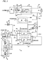
- Figure 2 is a schematic block diagram of an integrated environmental control system according to the present invention for the RAH-66 Comanche helicopter of Figure 1
- Referring now to the drawings wherein like reference characters identify corresponding or similar elements throughout the several views; Figure 1 is a perspective view of the RAH-66 Comanche helicopter being developed by the team of Sikorsky Aircraft (a division of United Technologies Corporation) and Boeing Helicopters. The
Comanche helicopter 100 has been configured with line-replaceable avionics/electronic modules (identified) generally by reference numeral 102) located for easy accessibility in the fuselage in left and right mission equipment package (MEP)bays 104, 106 (see Figure 2). Additional avionics/electronic modules are located in amid MEP bay 108 located behind acockpit 110 bulkhead. Further avionics/electronic modules are located within thecockpit 110. - An embodiment of an integrated environmental control (IEC)
system 10, as illustrated in Figure 2 and described hereinbelow in further detail, is design optimized for the RAH-66helicopter 100, and incorporates in operative combination the components of an environmental control system (ECS) and a nuclear/biological/chemical life support system (NBC LSS). TheIEC system 10 according to the present invention is operative to provide super-cooled, super-dry, decontaminated airflow, in seriatim, to the left andright MEP bays helicopter cockpit 110 for cooling of avionics/electronic modules and crew comfort. TheIEC system 10 is further operative to provide cooled, super-dry, decontaminated airflow for cooling the avionics/electronic modules in themid MEP bay 108 and for over pressurizing the left andright MEP bays IEC system 10 according to the present invention may be configured to provide super-cooled, super-dry, decontaminated airflow, in seriatim, for cooling avionics/electronic modules and crew comfort for helicopters having different avionics/electronic compartment and/or cockpit configurations. - The embodiment of the
IEC system 10 according to the present invention is illustrated in Figure 2, and includes arefrigerant subsystem 12, a regenerativeheat exchange apparatus 14, adecontamination subsystem 16, and anairflow distribution network 20. TheIEC system 10 provides a decontaminated, temperature regulated airflow for in seriatim cooling of the avionics/electronic modules of the left andright MEP bays helicopter cockpit 110, as well as for subsequent cooling of the avionics/electronic modules of themid MEP bay 108 and over pressurization of the left andright MEP bays IEC system 10 according to the present invention is an enhanced efficiency system that eliminates the need for ancillary heat exchange apparatus and reduces the overall aircraft system weight. - The
refrigerant subsystem 12 is operative to provide compressed airflow to the regenerativeheat exchange apparatus 14 and, in combination with thedecontamination subsystem 16, to provide super-cooled, super-dry, decontaminated airflow to theairflow distribution network 20. Compressed airflow is supplied to therefrigerant subsystem 12 from a subsystem power unit (SPU) of the helicopter 100 (engine bleed air of the RAH-66 Comanche helicopter was determined not to have sufficient inherent energy for utilization in the IEC system 10). The SPU, which is functionally similar to an auxiliary power unit (APU), is operative during helicopter operations to provide compressed airflow to therefrigerant subsystem 12. - The
refrigerant subsystem 12 for the embodiment of theIEC system 10 described herein is an air cycle machine (ACM) that includes acompressor stage 22 and aturbine stage 24. The regenerativeheat exchange apparatus 14 and thedecontamination subsystem 16 are operatively interposed between thecompressor stage 22 and theturbine stage 24 of theAGM 12. Thecompressor stage 22 is operative to increase the pressure of the compressed airflow supplied by the SPU. The highly compressed airflow from thecompressor stage 22 is channeled to and through the regenerativeheat exchange apparatus 14 to thedecontamination subsystem 16 via aflow duct 26. - The regenerative
heat exchange apparatus 14 is operative to transfer thermal energy from the highly compressed airflow from theAGM 12 inflow duct 26 to a thermally adjacent leg of apurge duct 28. Thepurge duct 28 accommodates purge airflow bled from theairflow distribution network 20, the purge airflow being utilized for purging thedecontamination subsystem 16, as described hereinbelow. The regenerativeheat exchange apparatus 14 is operative to raise the purge airflow inpurge duct 28 to a predetermined temperature that facilitates the purging process occurring in thedecontamination subsystem 16. - The
decontamination subsystem 16 of the described embodiment of theIEC system 10 is a pressure swing adsorber (PSA) NBC filtration apparatus of the type known in the art. ThePSA apparatus 16 comprises aninlet transfer valve 30, a high efficiency particulate air (HEPA)filter 32, two regenerative beds 34-1, 34-2 of the type described in U.S. Patent No. 4,769,052, and available from the Pall Corporation, New York, and anoutlet transfer valve 36. ThePSA apparatus 16 is operative to remove particulate, liquid, and/or gaseous contaminants from the highly compressed airflow provided by theflow duct 26. In particular, thePSA apparatus 16 is operative to remove substantially all moisture content from the highly compressed airflow. - The
inlet transfer valve 30 is operative to alternatively direct the compressed airflow from theflow duct 26 through theHEPA filter 32 to one of beds (34-2 as illustrated in Figure 2) of thePSA apparatus 16 and the purge airflow from thepurge duct 28 through the other bed (34-1 as illustrated in Figure 2) and vice versa. Particulate, liquid, and gaseous contaminants, and in particular the moisture content, of the highly compressed airflow are removed therefrom by means of the combination of theHEPA filter 32 and the active bed (34-2). Concomitantly, the contaminated bed (34-1) is being purged of entrapped contaminants by means of the purge airflow. Once the active bed is saturated, and/or the contaminated bed is purged of contaminants, theinlet transfer valve 30 is activated to redirect the highly compressed airflow and the purge airflow through the newly-purged bed and the newly-contaminated bed, respectively. TheHEPA filter 32 and two regeneration beds 34-1, 34-2 thus provide a means for continuously decontaminating the highly compressed airflow, as well as removing substantially all moisture content thereof, from thecompressor stage 22 of theAGM 12. - The
outlet transfer valve 36 is operative to direct the contaminated purge airflow into anexhaust duct 38 so that the contaminated airflow is dumped overboard. Theoutlet transfer valve 36 is concomitantly operative to direct the super-dry, decontaminated airflow produced by thePSA apparatus 16 to theturbine stage 24 of theAGM 12 by means of aflow duct 40. The automatic flight control system computer (not illustrated) of thehelicopter 100 may be utilized to synchronously regulate the switching operations of the inlet andoutlet transfer valves turbine stage 24 is operative to extract thermal energy from the super-dry, decontaminated airflow of flow duct 40 (by expansion of the super-dry, decontaminated airflow) to provide a super-cooled, super-dry, decontaminated airflow to theairflow distribution network 20. For the described embodiment of theIEC system 20 for the RAH-66helicopter 100, the super-cooled, super-dry, decontaminated airflow provided to theairflow distribution network 20 by theturbine stage 24 of theACM 12 has a volumetric flowrate of about 33 ppm, a temperature of approximately -34°C to -40°C (-30°F to -40°F), a pressure of about 1 - 1½ psig, and substantially 0% moisture content (a dew point of about -73°C to -90°C (-100°F to -130°F)). Theturbine stage 24 also provides the necessary power to drive thecompressor stage 22. - The
airflow distribution network 20 comprises a plurality of distribution ducts that are operative to channel the super-cooled, super-dry, decontaminated airflow from therefrigerant subsystem 12, in seriatim, directly to the left andright MEP bays cockpit 110 for cooling the avionics/electronic modules and crew comfort. In addition, due to the initial thermal cooling capacity of the super-cooled, super-dry, decontaminated airflow, thedistribution network 20 is further operative to directly provide cooled, super-dry, decontaminated airflow (the cooling airflow discharged from the left andright MEP bays 104, 106) for cooling the avionics/electronic modules in themid MEP bay 108 and for over pressurizing the left andright MEP bays distribution network 20, there is little likelihood of moisture condensation and/or freezing when the super-cooled, super-dry, decontaminated airflow encounters the avionics/electronic modules in the left andright MEP bays mid MEP bay 108, and/or thecockpit 110. - Thus, the airflow may be used directly (without the need for a supplemental heat exchange apparatus to heat the airflow to preclude moisture condensation and/or freezing) to provide cooling for the avionics/electronic modules. Furthermore, due to the enhanced thermal cooling capacity of the super-cooled, super-dry, decontaminated airflow, the volumetric flowrate of the airflow required for proper cooling of the avionics/electronic modules is drastically reduced. This, in turn, means that lighter components may be used for the ECS portion of the
IEC system 10. More importantly, theairflow distribution network 20 can incorporate smaller diameter distribution ducts. These features in combination allow a significant reduction in overall weight of theIEC system 10. - A first distribution duct 20-1 channels the airflow from the
turbine stage 24 of theACM 12 to the left andright MEP bays right MEP bays IEC system 10, the super-cooled, super-dry, decontaminated airflow is directly utilized to provide conductive cooling of the avionics/electronic modules by means ofMEP bay coldplates coldplates IEC system 10 for theComanche helicopter 100 to ensure that the avionics/electronic modules are not physically exposed to any contaminants remaining in the super-cooled, super-dry, decontaminated airflow. It will be appreciated, however, that the super-cooled, super-dry, decontaminated airflow may be alternatively directed through the avionics/electronic modules for convective cooling thereof. - The
coldplates respective coldplates coldplates right MEP bays coldplates coldplates right MEP bays - The airflow discharged from the
coldplates IEC system 10, to about 10°C - 15°C (about 50°F - 60°F)), super-dry, decontaminated airflow. This airflow has sufficient thermal cooling capacity to provide cooling of the avionics/electronic modules in themid MEP bay 108 and for the avionics/electronic modules in thecockpit 110 as well as providing crew comfort. The airflow is channeled, by means of downstream parallel distribution ducts 20-4, 20-5, to a common distribution duct 20-6. The common distribution duct 20-6 is operative to channel the cooled, super-dry, decontaminated airflow to thecockpit 110. - The
purge duct 28 described hereinabove is interconnected to the common distribution duct 20-6 downstream of the left andright MEP bays PSA apparatus 16. A diverter duct 20-7 is interconnected to the common distribution duct 20-6 to bleed of another portion of the cooled, super-dry, decontaminated airflow for cooling the avionics/electronic modules in themid MEP bay 108 and for over pressurizing the left andright MEP bays - Airflow in the diverter duct 20-7 is channeled to a
coldplate 116 in themid MEP bay 108 by means of a first subdistribution duct 20-8. The midMEP bay coldplate 116 is equivalent in structure and function to thecoldplates mid MEP bay 108 so as to maintain the avionic/electronic modules at proper operating temperatures.. The airflow exiting thecoldplate 116 is dumped overboard. The airflow in the diverter duct 20-7 is also channeled into the left andright MEP bays right MEP bays - The cooled, super-dry, decontaminated airflow channeled into the
cockpit 110 by means of the common distribution duct 20-6 is utilized for crew comfort. In addition, such airflow is circulated through avionics/equipment bays cockpit 110 for cooling of avionics/electronic modules disposed therein. The cooling airflow channeled into the avionics/equipment bays cockpit 110 proper by means of a circulation subsystem 50 (comprising ducting from thebays cockpit 110 further includes apressure control valve 52 that is operative to channel excessive cockpit cooling airflow to an electro-optical sensor system 122 for cooling thereof, such airflow being subsequently dumped overboard. - The described embodiment of the
IEC system 10 for theComanche helicopter 100 further includes an ambient back-upsubsystem 60 that includes first and second means 62, 64 for providing pressurized airflow, first and second cut-invalves dump valve 70, andinterconnect ducts subsystem 60 is operative, in response to a loss of the functional capability of theIEC system 10, i.e., loss of cooling airflow due to malfunctioning and/or shutdown of theACM 12 and/or thePSA apparatus 16, to provide pressurized airflows that provide a minimal level of cooling for the avionics/electronic modules of the left, right, andmid MEP bays cockpit 110 so as to maintain the avionics/electronic modules in an operating condition, and for minimal crew comfort. - The first means 62, the
first interconnect duct 72, the first cut-invalve 66, and thedump valve 70 are operative in combination to provide a first pressurized airflow for providing a minimal level of cooling of the avionics/electronic modules of the left andright MEP bays first interconnect duct 72 and the first cut-invalve 66. The distribution scheme of the first pressurized airflow for the left andright MEP bays dump valve 70 is operative to dump the first pressurized airflow overboard immediately downstream of the left andright MEP bays - The second means 64, the
second interconnect duct 74, and the second cut-invalve 68 are operative in combination to provide a second pressurized airflow for providing a minimal level of cooling for the avionics/electronic modules of themid MEP bay 108 and thecockpit 110 and for crew comfort. The second means 64 utilizes ambient air to provide the second pressurized airflow, which is channeled to the common distribution duct 20-6 by means of thesecond interconnect duct 74 and the second cut-invalve 68. The distribution scheme of the second pressurized airflow is equivalent to the distribution scheme of the cooled, super-dry, decontaminated airflow described hereinabove. Functionally, however, the second pressurized airflow provides only a minimal level of cooling for the avionics/electronic modules and crew comfort due to its diminished thermal cooling capacity. In addition, the second pressurized airflow is not decontaminated, and has a moisture content substantially equivalent to the ambient air. - The described embodiment of the
IEC system 10 may further include an auxiliaryheat exchange subsystem 80 that comprises ableed air duct 82 and aheat exchange apparatus 84. The auxiliaryheat exchange subsystem 80 is operative to heat the cooled, super-dry, decontaminated air provided to thecockpit 110 via the common distribution duct 20-6 for crew comfort during cold weather flight operations. Thebleed air duct 82 channels bleed airflow from the helicopter engines (not identified) to theheat exchange apparatus 84. Theheat exchange apparatus 84 is operative to transfer thermal energy from the bleed airflow in thebleed air duct 82 to the cooled, super-dry, decontaminated airflow in the common distribution duct 20-6 to raise the temperature thereof for crew comfort. - The described embodiment of the
IEC system 10 may also include arecirculation subsystem 90 that includes recirculation ducting 92-1, 92-2 and a recirculating fan 94. Therecirculation subsystem 90 is operative to recirculate the cooled, super-dry, decontaminated airflow that has been introduced into thecockpit 110 proper via the common distribution duct 20-6. - A variety of modification and variations are possible in light of the above teachings. It is therefore to be understood that, within the scope of the appended claims, the invention may be practiced otherwise than as specifically described hereinabove.
Claims (13)
- An integrated environmental control system (10) for a helicopter having a plurality of mission equipment package bays (104, 106, 108, 118, 120) containing electronic modules (102), the helicopter having a cockpit (110) that contains electronic modules, comprising:a refrigerant subsystem (12) operative to provide a highly compressed airflow;a decontamination subsystem (16) operative to decontaminate and demoisturize said highly compressed airflow from said refrigerant subsystem (12) to provide a super-dry, decontaminated airflow;said refrigerant subsystem (12) being further operative to super cool said super-dry, decontaminated airflow from said decontamination subsystem (16) to provide a super-cooled, super-dry, decontaminated airflow; andan airflow distribution network (20);characterized in that
said airflow distribution network (20: 20-1, 20-2 or 20-3, 20-4 or 20-5, and 20-6) is operative to channel said super-cooled, super-dry, decontaminated airflow, in seriatim, directly to at least one of the plurality of mission equipment package bays (104 or 106) and the cockpit (110) for cooling the electronic modules (102) thereof and crew comfort. - The integrated environmental control system (10) of claim 1 characterized in that said airflow distribution network (20: 20-1, 20-2 or 20-3, 20-4 or 20-5, and 20-6) includes ducting means (20-7, 20-8) downstream of the at least one mission equipment bay (104 or 106) for diverting cooled, super-dry, decontaminated airflow discharged from the at least one mission equipment bay (104 or 106) to another of the plurality of mission equipment bays (108) for cooling the electronic modules (102) thereof.
- The integrated environmental control system (10) of claim 2 characterized in that ducting means (20-7, 20-8, 20-9) is further operative to channel said cooled, super-dry, decontaminated airflow to the at least one mission equipment bay (104 or 106) for overpressurization thereof to prevent contaminant infiltration thereof.
- The integrated environmental control system (10) of claim 2 characterized by an auxiliary heat exchange subsystem (80) disposed in operative combination with said airflow distribution network (20-6) upstream of the cockpit (110) for heating said cooled, super-dry, decontaminated airflow discharged from the at least one mission equipment package bay (104 or 106) for crew comfort during cold weather flight operations.
- The integrated environmental control system (10) of claim 1 characterized by an ambient back-up subsystem (60: 62, 72, 66, 70 and 62, 74, 68) fluidically interconnected to said airflow distribution network (20: 20-1 and 20-6) for providing emergency cooling airflow to the at least one mission equipment package bay (104 or 106) and the cockpit (110) for cooling the electronic modules (102) thereof and crew comfort.
- An integrated environment control system (10) for a helicopter (100) having left, right, and mid mission equipment package bays (104, 106, 108) containing electronic modules (102), the helicopter (100) having a cockpit (110) that includes electronic modules (102), comprising:an air cycle machine (12) that includes a compressor stage (22) and a turbine stage (24), said compressor stage (22) being operative to provide a highly compressed airflow;means (28) for providing a purge airflow;a regenerative heat exchange apparatus (14) operative to transfer thermal energy from said highly compressed airflow to said purge airflow;a pressure swing adsorber, nuclear/biological/chemical filtration apparatus (16) that includes a high efficiency particulate air filter (32) and first and second alternatively operative regenerative beds (34-1, 34-2) that are operative in combination to decontaminate and demoisturize said highly compressed airflow to provide a super-dry, decontaminated airflow, said second and first regenerative beds (34-2, 34-1) being alternatively purged of contaminants by said purge airflow;said turbine stage (24) of said air cycle machine (12) being operative to super cool said super-dry, decontaminated airflow to provide a super-cooled, super-dry, decontaminated airflow; andan airflow distribution network;characterized in that
said airflow distribution network (20: 20-1, 20-2, 20-3, 20-4, 20-5, and 20-6) is operative to channel said super-cooled, super-dry, decontaminated airflow, in seriatim, directly to the left and right mission equipment package bays (104, 106) and the cockpit (110) for cooling the electronic modules (102) thereof and crew comfort;
said airflow distribution network (20: 20-1, 20-2, 20-3, 20-4, 20-5, and 20-6) includinga first distribution duct (20-1) for channeling said super-cooled, super-dry, decontaminated airflow directly to the left and right mission equipment package bays (104, 106),upstream parallel distribution ducts (20-2, 20-3) fluidically interconnected to said first distribution duct (20-1) for directing said super-cooled, super-dry, decontaminated airflow directly to the left and right mission equipment package bays (104, 106), respectively, for cooling the electronic modules (102) thereof,downstream parallel distribution ducts (20-4, 20-5) for receiving cooled, super-dry, decontaminated airflow discharged from the left and right mission equipment package bays (104, 106), respectively, anda common distribution duct (20-6) fluidically interconnected to said downstream parallel distribution ducts (20-4, 20-5) for channeling said cooled, super-dry, decontaminated airflow to the cockpit (110) for cooling the electronic modules (102) therein and crew comfort. - The integrated environmental control system (10) of claim 6 characterized in that said airflow distribution network (20: 20-1, 20-2, 20-3, 20-4, 20-5, and 20-6) further comprisesa diverter duct (20-7) fluidically interconnected to said common distribution duct (20-6), anda first subdistribution duct (20-8) fluidically interconnected to said diverter duct (20-7) and to the mid mission equipment package bay (108),said diverter duct (20-7) and said first subdistribution duct (20-8) in combination being operative to channel a first portion of said cooled, super-dry, decontaminated airflow from said common distribution duct (20-6) to the mid mission equipment package bay (108) for cooling the electronic modules (102) thereof.
- The integrated environmental control system (10) of claim 7 characterized in that said airflow distribution network (20: 20-1, 20-2, 20-3, 20-4, 20-5, 20-6. 20-7, 20-8) further includes a second subdistribution duct (20-9) fluidically interconnected to said diverter duct (20-7) and the left and right mission equipment package bays (104, 106), said diverter duct (20-7) and said second subdistribution duct (20-9) in combination being operative to channel a second portion of said cooled, super-dry, decontaminated airflow from said common distribution duct (20-6) to the left and right mission equipment package bays (104, 106) for overpressurization thereof to preclude contaminant infiltration thereof.
- The integrated environment control system (10) of claim 6 characterized by a subsystem power unit (SPU) fluidically interconnected to said compressor stage (22) of said air cycle machine (12) and operative to provide compressed airflow to said compressor stage (22) of said air cycle machine (12) during helicopter operations, said compressor stage (22) being operative to compress said compressed airflow to provide said highly compressed airflow.
- The integrated environmental control system (10) of claim 6 characterized in that said purge airflow providing means (28) comprises a purge duct (28) fluidically interconnected to said common distribution duct (20-6) downstream of the left and right mission equipment package bays (104, 106) and to said pressure swing adsorber, nuclear/biological/chemical filtration apparatus (16), said purge duct (28) being disposed in a thermally adjacent relationship with said regenerative heat exchange apparatus (14).
- The integrated environmental control system (10) of claim 6 characterized in that said airflow distribution network (20: 20-1, 20-2, 20-3, 20-4, 20-5, and 20-6) further comprises left and right coldplates (112, 114) disposed in the left and right mission equipment package bays (104, 106), respectively, and fluidically interconnected respectively to said upstream and downstream parallel distribution ducts (20-2, 20-3; 20-4, 20-5), the electronic modules (102) of the left and right mission equipment package bays (104, 106) being physically attached to said left and right coldplates (112, 114), respectively, so as to provide thermally conductive pathways therebetween.
- The integrated environmental control system (10) of claim 6 characterized by an ambient back-up subsystem (60: 62, 72, 66, 70 and 62, 74, 68) fluidically interconnected to said first distribution duct (20-1) and said common distribution duct (20-6) to provide emergency cooling airflow to the left and right mission equipment package bays (104, 106) and the cockpit (110), respectively, for cooling the electronic modules (102) thereof and crew comfort.
- The integrated environmental control system (10) of claim 6 characterized by an an auxiliary heat exchange subsystem (80) disposed in combination with said common distribution duct (20-6) and operative to heat said cooled, super-dry, decontaminated airflow provided to the cockpit (110) via said common distribution duct (20-6) for crew comfort during cold weather flight operations.
Applications Claiming Priority (3)
| Application Number | Priority Date | Filing Date | Title |
|---|---|---|---|
| US07/992,392 US5327744A (en) | 1992-12-18 | 1992-12-18 | Integrated environmental control system for a helicopter |
| US992392 | 1992-12-18 | ||
| PCT/US1993/012100 WO1994014651A1 (en) | 1992-12-18 | 1993-12-13 | An integrated environmental control system for a helicopter |
Publications (2)
| Publication Number | Publication Date |
|---|---|
| EP0673330A1 EP0673330A1 (en) | 1995-09-27 |
| EP0673330B1 true EP0673330B1 (en) | 1997-03-12 |
Family
ID=25538289
Family Applications (1)
| Application Number | Title | Priority Date | Filing Date |
|---|---|---|---|
| EP94904435A Expired - Lifetime EP0673330B1 (en) | 1992-12-18 | 1993-12-13 | An integrated environmental control system for a helicopter |
Country Status (9)
| Country | Link |
|---|---|
| US (1) | US5327744A (en) |
| EP (1) | EP0673330B1 (en) |
| JP (1) | JP3476460B2 (en) |
| KR (1) | KR950704153A (en) |
| CA (1) | CA2147833A1 (en) |
| DE (1) | DE69308887T2 (en) |
| ES (1) | ES2100044T3 (en) |
| IL (3) | IL120315A (en) |
| WO (1) | WO1994014651A1 (en) |
Cited By (1)
| Publication number | Priority date | Publication date | Assignee | Title |
|---|---|---|---|---|
| EP3292007B1 (en) | 2015-05-07 | 2022-10-26 | Rheinmetall Landsysteme GmbH | Cooling system of a combat vehicle, and pressure cascade for cooling at least one electronic unit in a combat vehicle by means of a cooling system |
Families Citing this family (29)
| Publication number | Priority date | Publication date | Assignee | Title |
|---|---|---|---|---|
| US5929323A (en) * | 1996-08-08 | 1999-07-27 | Ohayon; Shalom | Barometric and altimeter bomb detection and midair explosion avoidance system for airplanes |
| US5701755A (en) * | 1997-01-15 | 1997-12-30 | Sundstrand Corporation | Cooling of aircraft electronic heat loads |
| US5918458A (en) * | 1997-02-14 | 1999-07-06 | General Electric Company | System and method of providing clean filtered cooling air to a hot portion of a gas turbine engine |
| US5993216A (en) * | 1997-09-26 | 1999-11-30 | Stogner; Robert B. | Multi-functional enclosure |
| GB2334094B (en) * | 1998-02-05 | 2002-08-14 | Howden Aircontrol Ltd | Air environment control systems |
| US6381969B1 (en) | 1999-12-17 | 2002-05-07 | Honeywell International Inc. | ECS with 2-stage water separation |
| USH2221H1 (en) * | 2000-02-15 | 2008-08-05 | The United States Of America As Represented By The Secretary Of The Navy | Air supply system particularly suited to remove contaminants created by chemical, biological or radiological conditions |
| US6402812B1 (en) | 2001-04-25 | 2002-06-11 | Sikorsky Aircraft Corporation | Filtered environmental control system |
| US6666039B2 (en) | 2001-07-05 | 2003-12-23 | Shimadzu Corporation | Aircraft air conditioner |
| US6722137B2 (en) | 2001-08-17 | 2004-04-20 | General Electric Co. | Methods and apparatus for regulating turbine clearance control system airflow |
| US6701715B2 (en) * | 2002-05-02 | 2004-03-09 | Honeywell International, Inc. | Variable geometry ejector for a bleed air system using integral ejector exit pressure feedback |
| US7052525B2 (en) * | 2002-08-13 | 2006-05-30 | Ensco, Inc. | Vehicle integrated protective system |
| US6775990B2 (en) * | 2002-10-17 | 2004-08-17 | Mark Douglas Swinford | Methods and apparatus for regulating gas turbine engine fluid flow |
| GB2402736B (en) * | 2003-06-13 | 2007-04-11 | Aircontrol Technologies Ltd | Air environment control system |
| CA2433496C (en) * | 2003-06-20 | 2008-12-09 | Heinz Reichle | Blower assisted heating and defogging system for small aircraft |
| US7622074B2 (en) * | 2005-06-28 | 2009-11-24 | Steris Inc. | Integrated decontamination/aeration system for vehicles |
| DE102006001685B4 (en) * | 2006-01-12 | 2009-11-12 | Airbus Deutschland Gmbh | Method and system for controlling the pressure in an aircraft cabin |
| US20090084896A1 (en) | 2007-09-27 | 2009-04-02 | Hamilton Sundstrand Corporation | Cabin air system for aviation electronics |
| DE102008058451B4 (en) * | 2008-11-21 | 2010-11-18 | Airbus Deutschland Gmbh | Method and system for emergency ventilation of an aircraft cabin in the event of a leak in the area of an air mixer |
| JP5208817B2 (en) * | 2009-03-10 | 2013-06-12 | 株式会社東芝 | Aircraft cooling system |
| US20110105008A1 (en) * | 2009-10-30 | 2011-05-05 | Honeywell International Inc. | Catalytic air purification system for a vehicle using multiple heat sources from an engine |
| US20110233433A1 (en) * | 2010-03-29 | 2011-09-29 | Dehais John M | Sealed flapper diverter valve |
| US8976525B2 (en) | 2012-07-31 | 2015-03-10 | General Electric Company | Systems and methods for dissipating heat in an enclosure |
| RU2537092C2 (en) * | 2013-01-18 | 2014-12-27 | Общество с ограниченной ответственностью "Ди-Эс-Эр" | Method of environmental monitoring and system for its realisation |
| US10647304B2 (en) | 2013-03-14 | 2020-05-12 | Carl Heinz Reichle | Anti-fogging system for single engine aircraft |
| US20140299707A1 (en) * | 2013-04-04 | 2014-10-09 | Bell Helicopter Textron Inc. | Preventing Condensation on Environmental Control System Fluid Lines |
| US9187180B2 (en) | 2013-05-24 | 2015-11-17 | Hamilton Sundstrand Corporation | Thermal pneumatic deicing system for an aircraft RAM air heat exchanger |
| DE102017211561A1 (en) * | 2017-07-06 | 2019-01-10 | Siemens Aktiengesellschaft | Airplane with a power electronic component |
| CN114084353B (en) * | 2021-11-17 | 2023-11-24 | 沈阳航空航天大学 | Nuclear biochemical protection system for helicopter cabin |
Family Cites Families (17)
| Publication number | Priority date | Publication date | Assignee | Title |
|---|---|---|---|---|
| GB850358A (en) * | 1957-08-23 | 1960-10-05 | United Aircraft Corp | Aircraft air-conditioning systems |
| US2991706A (en) * | 1958-02-03 | 1961-07-11 | United Aircraft Corp | System for distributing conditioned air in aircraft |
| US4209993A (en) * | 1978-03-06 | 1980-07-01 | United Technologies Corp. | Efficiency air cycle environmental control system |
| US4262495A (en) * | 1979-09-20 | 1981-04-21 | The Boeing Company | Cabin-air recirculation system powered by cabin-to-ambient pressure differential |
| US4312191A (en) * | 1980-02-15 | 1982-01-26 | Sundstrand Corporation | Environmental control system for aircraft with improved efficiency |
| US4419926A (en) * | 1980-09-02 | 1983-12-13 | Lockheed Corporation | ESC energy recovery system for fuel-efficient aircraft |
| US4434624A (en) * | 1981-03-27 | 1984-03-06 | Lockheed Corporation | Energy-efficient all-electric ECS for aircraft |
| US4490989A (en) * | 1982-02-16 | 1985-01-01 | Aero Engineering Corporation | Helicopter heating and air conditioning system |
| US4550573A (en) | 1983-12-12 | 1985-11-05 | United Technologies Corporation | Multiple load, high efficiency air cycle air conditioning system |
| US4674704A (en) * | 1985-12-03 | 1987-06-23 | The United States Of America As Represented By The Secretary Of The Air Force | Direct air cooling system for airborne electronics |
| US4769051A (en) * | 1987-10-19 | 1988-09-06 | United Technologies Corporation | Filtered environmental control system |
| US4829775A (en) * | 1988-05-02 | 1989-05-16 | United Technologies Corporation | Filtered environmental control system |
| US4978064A (en) * | 1988-12-29 | 1990-12-18 | Air Comm Corporation | System and method of heat distribution in engine powered craft |
| US5014518A (en) * | 1989-06-23 | 1991-05-14 | Allied-Signal Inc. | ECS with advanced air cycle machine |
| JPH03129267A (en) * | 1989-10-10 | 1991-06-03 | Aisin Seiki Co Ltd | Air conditioner |
| US5165597A (en) * | 1991-03-11 | 1992-11-24 | Air Comm Corporation | Air moving apparatus and method for vehicles |
| US5151022A (en) * | 1991-10-03 | 1992-09-29 | Allied-Signal Inc. | Environmental control system with catalytic filter |
-
1992
- 1992-12-18 US US07/992,392 patent/US5327744A/en not_active Expired - Lifetime
-
1993
- 1993-12-07 IL IL12031593A patent/IL120315A/en not_active IP Right Cessation
- 1993-12-07 IL IL107926A patent/IL107926A/en not_active IP Right Cessation
- 1993-12-13 ES ES94904435T patent/ES2100044T3/en not_active Expired - Lifetime
- 1993-12-13 JP JP51524194A patent/JP3476460B2/en not_active Expired - Fee Related
- 1993-12-13 KR KR1019950702497A patent/KR950704153A/en not_active Ceased
- 1993-12-13 DE DE69308887T patent/DE69308887T2/en not_active Expired - Fee Related
- 1993-12-13 CA CA002147833A patent/CA2147833A1/en not_active Abandoned
- 1993-12-13 WO PCT/US1993/012100 patent/WO1994014651A1/en not_active Ceased
- 1993-12-13 EP EP94904435A patent/EP0673330B1/en not_active Expired - Lifetime
-
1997
- 1997-02-25 IL IL12031597A patent/IL120315A0/en unknown
Cited By (2)
| Publication number | Priority date | Publication date | Assignee | Title |
|---|---|---|---|---|
| EP3292007B1 (en) | 2015-05-07 | 2022-10-26 | Rheinmetall Landsysteme GmbH | Cooling system of a combat vehicle, and pressure cascade for cooling at least one electronic unit in a combat vehicle by means of a cooling system |
| EP3292007B2 (en) † | 2015-05-07 | 2025-12-17 | Rheinmetall Landsysteme GmbH | Cooling system of a combat vehicle, and pressure cascade for cooling at least one electronic unit in a combat vehicle by means of a cooling system |
Also Published As
| Publication number | Publication date |
|---|---|
| DE69308887T2 (en) | 1997-10-16 |
| JPH08504704A (en) | 1996-05-21 |
| CA2147833A1 (en) | 1994-07-07 |
| US5327744A (en) | 1994-07-12 |
| IL120315A (en) | 1999-03-12 |
| DE69308887D1 (en) | 1997-04-17 |
| IL120315A0 (en) | 1997-06-10 |
| KR950704153A (en) | 1995-11-17 |
| ES2100044T3 (en) | 1997-06-01 |
| IL107926A (en) | 1998-02-22 |
| JP3476460B2 (en) | 2003-12-10 |
| EP0673330A1 (en) | 1995-09-27 |
| WO1994014651A1 (en) | 1994-07-07 |
Similar Documents
| Publication | Publication Date | Title |
|---|---|---|
| US5327744A (en) | Integrated environmental control system for a helicopter | |
| US6402812B1 (en) | Filtered environmental control system | |
| US6449963B1 (en) | Aircraft air conditioning system and method | |
| US4966005A (en) | Advanced hybrid air/vapor cycle ECS | |
| US5516330A (en) | Air conditioning system for a passenger aircraft | |
| EP0313504B1 (en) | Filtered environmental control system | |
| CA2773229C (en) | Aircraft system and method for improved cooling efficiency | |
| US7121100B2 (en) | High efficiency aircraft cabin air supply cooling system | |
| US4829775A (en) | Filtered environmental control system | |
| US20080110193A1 (en) | Environmental control system with adsorption based water removal | |
| US20100084118A1 (en) | Cooling system for aircraft electric or electronic devices | |
| JP4211196B2 (en) | Air conditioner for aircraft | |
| US20210197975A1 (en) | Aircraft environmental control system | |
| US12006045B2 (en) | Regenerative filter system | |
| EP3845455B1 (en) | Aircraft environmental control system | |
| US6786279B2 (en) | Forward in flight (IFE) entertainment cooling system | |
| JP4023018B2 (en) | Aircraft environmental control equipment | |
| JP4362967B2 (en) | Air conditioner | |
| JPH02256596A (en) | Air conditioner for aircraft | |
| KR100231839B1 (en) | NBC collective protection system | |
| JP2000203495A (en) | Aircraft environmental control device | |
| Martin et al. | Air handling and atmosphere conditioning systems for manned spacecraft: a design and performance data survey | |
| Eckert et al. | ATMOSPHERE REVITALIZATION FOR SPACELAB | |
| National Research Council | Environmental Control | |
| Williams et al. | International Space Station Environmental Control and Life Support System On-Orbit Station Development Test Objective Status |
Legal Events
| Date | Code | Title | Description |
|---|---|---|---|
| PUAI | Public reference made under article 153(3) epc to a published international application that has entered the european phase |
Free format text: ORIGINAL CODE: 0009012 |
|
| 17P | Request for examination filed |
Effective date: 19950614 |
|
| AK | Designated contracting states |
Kind code of ref document: A1 Designated state(s): DE ES FR GB IT NL |
|
| GRAG | Despatch of communication of intention to grant |
Free format text: ORIGINAL CODE: EPIDOS AGRA |
|
| 17Q | First examination report despatched |
Effective date: 19960322 |
|
| GRAH | Despatch of communication of intention to grant a patent |
Free format text: ORIGINAL CODE: EPIDOS IGRA |
|
| GRAH | Despatch of communication of intention to grant a patent |
Free format text: ORIGINAL CODE: EPIDOS IGRA |
|
| GRAA | (expected) grant |
Free format text: ORIGINAL CODE: 0009210 |
|
| AK | Designated contracting states |
Kind code of ref document: B1 Designated state(s): DE ES FR GB IT NL |
|
| PG25 | Lapsed in a contracting state [announced via postgrant information from national office to epo] |
Ref country code: NL Free format text: LAPSE BECAUSE OF FAILURE TO SUBMIT A TRANSLATION OF THE DESCRIPTION OR TO PAY THE FEE WITHIN THE PRESCRIBED TIME-LIMIT Effective date: 19970312 |
|
| ITF | It: translation for a ep patent filed | ||
| REF | Corresponds to: |
Ref document number: 69308887 Country of ref document: DE Date of ref document: 19970417 |
|
| ET | Fr: translation filed | ||
| REG | Reference to a national code |
Ref country code: ES Ref legal event code: FG2A Ref document number: 2100044 Country of ref document: ES Kind code of ref document: T3 |
|
| NLV1 | Nl: lapsed or annulled due to failure to fulfill the requirements of art. 29p and 29m of the patents act | ||
| PLBE | No opposition filed within time limit |
Free format text: ORIGINAL CODE: 0009261 |
|
| STAA | Information on the status of an ep patent application or granted ep patent |
Free format text: STATUS: NO OPPOSITION FILED WITHIN TIME LIMIT |
|
| 26N | No opposition filed | ||
| PGFP | Annual fee paid to national office [announced via postgrant information from national office to epo] |
Ref country code: ES Payment date: 19981215 Year of fee payment: 6 |
|
| PG25 | Lapsed in a contracting state [announced via postgrant information from national office to epo] |
Ref country code: ES Free format text: LAPSE BECAUSE OF NON-PAYMENT OF DUE FEES Effective date: 20001214 |
|
| REG | Reference to a national code |
Ref country code: GB Ref legal event code: IF02 |
|
| REG | Reference to a national code |
Ref country code: ES Ref legal event code: FD2A Effective date: 20010113 |
|
| PGFP | Annual fee paid to national office [announced via postgrant information from national office to epo] |
Ref country code: GB Payment date: 20051104 Year of fee payment: 13 |
|
| PGFP | Annual fee paid to national office [announced via postgrant information from national office to epo] |
Ref country code: FR Payment date: 20051201 Year of fee payment: 13 |
|
| PGFP | Annual fee paid to national office [announced via postgrant information from national office to epo] |
Ref country code: DE Payment date: 20051230 Year of fee payment: 13 |
|
| PGFP | Annual fee paid to national office [announced via postgrant information from national office to epo] |
Ref country code: IT Payment date: 20061231 Year of fee payment: 14 |
|
| PG25 | Lapsed in a contracting state [announced via postgrant information from national office to epo] |
Ref country code: DE Free format text: LAPSE BECAUSE OF NON-PAYMENT OF DUE FEES Effective date: 20070703 |
|
| GBPC | Gb: european patent ceased through non-payment of renewal fee |
Effective date: 20061213 |
|
| REG | Reference to a national code |
Ref country code: FR Ref legal event code: ST Effective date: 20070831 |
|
| PG25 | Lapsed in a contracting state [announced via postgrant information from national office to epo] |
Ref country code: GB Free format text: LAPSE BECAUSE OF NON-PAYMENT OF DUE FEES Effective date: 20061213 |
|
| PG25 | Lapsed in a contracting state [announced via postgrant information from national office to epo] |
Ref country code: FR Free format text: LAPSE BECAUSE OF NON-PAYMENT OF DUE FEES Effective date: 20070102 |
|
| PG25 | Lapsed in a contracting state [announced via postgrant information from national office to epo] |
Ref country code: IT Free format text: LAPSE BECAUSE OF NON-PAYMENT OF DUE FEES Effective date: 20071213 |