EP0672849B1 - Piston sealing assembly - Google Patents
Piston sealing assembly Download PDFInfo
- Publication number
- EP0672849B1 EP0672849B1 EP95301445A EP95301445A EP0672849B1 EP 0672849 B1 EP0672849 B1 EP 0672849B1 EP 95301445 A EP95301445 A EP 95301445A EP 95301445 A EP95301445 A EP 95301445A EP 0672849 B1 EP0672849 B1 EP 0672849B1
- Authority
- EP
- European Patent Office
- Prior art keywords
- groove
- assembly
- bore wall
- cylinder bore
- piston
- Prior art date
- Legal status (The legal status is an assumption and is not a legal conclusion. Google has not performed a legal analysis and makes no representation as to the accuracy of the status listed.)
- Expired - Lifetime
Links
Images


Classifications
-
- F—MECHANICAL ENGINEERING; LIGHTING; HEATING; WEAPONS; BLASTING
- F16—ENGINEERING ELEMENTS AND UNITS; GENERAL MEASURES FOR PRODUCING AND MAINTAINING EFFECTIVE FUNCTIONING OF MACHINES OR INSTALLATIONS; THERMAL INSULATION IN GENERAL
- F16J—PISTONS; CYLINDERS; SEALINGS
- F16J9/00—Piston-rings, e.g. non-metallic piston-rings, seats therefor; Ring sealings of similar construction
- F16J9/12—Details
- F16J9/20—Rings with special cross-section; Oil-scraping rings
Definitions
- This invention relates to the technology of sealing relatively moveable surfaces and more particularly to piston sealing assemblies that can substantially reduce friction, blow-by and peristaltic pumping.
- piston rings which are usually made of flat heat-resistant metal (split to allow for assembly and to exert a radial resiliency) sized to fit within straight sided grooves that allow for upward and downward shifting of the rings within their grooves.
- High pressure combustion gases at one side of the rings tend to force the ring against the opposite side of the groove, producing high frictional contact that prevents the ring from adjusting radially to maintain good sealing contact.
- Gases will migrate behind the ring and leak as the ring changes position between strokes or the gases will migrate past the outer periphery of the rings and leak as the rings fail to maintain annular contact (both effects are often referred to as blow-by).
- blow-by is the charge mass in the combustion chamber that leaks past the piston rings and accounts for about 4% of the brake specific fuel consumption (BSFC); friction is the useful energy expanded to overcome the friction between the piston/piston rings and the cylinder bore used is usually around 12% BSFC.
- BSFC brake specific fuel consumption
- the upward and downward shifting of the rings within their grooves allows liquid lubricants, such as oil splashed on the lower portion of the cylinder bore wall, to be unwantedly pumped upward into the combustion chamber as the oil gets trapped between the rings and released on a change of stroke. This is sometimes referred to as unintended peristaltic pumping.
- the shifting of the ring within the groove may involve twisting or inversion of its radial plane about it axis, sometimes referred to as flutter. This flutter can eventually wear away the sharp corners of the groove allowing even more exaggerated flutter, blow-by and peristaltic pumping.
- US Patent 4,350,352 is concerned with piston ring and groove assemblies which provide a seal between a piston ring side and an adjacent wall of a piston ring groove during engine operation even when the piston is eccentric or tilted relative to a cylinder within which said piston moves,
- An annular sealing element is positioned in the groove and is provided with smoothly curved and diverging concave side surfaces which are mateable with diverging convex shoulders on the groove.
- a sealing assembly for a cylinder bore wall having a piston moveable closely along such wall with a controlled gap therebetween.
- the assembly comprising: (a) walls, in at least one of said cylinder bore wall and piston, defining an annular groove facing the other of said cylinder bore wall or piston, the outer radial regions of said groove being smoothly curved to form a pair of oppositely facing and diverging convex shoulders; (b) an annular sealing element positioned in said groove and having (i) smoothly curved and diverging concave side surfaces mateable with said groove shoulders for supporting said element in said groove and (ii) a curved crown surface effective to tangentially contact said cylinder bore wall characterised in that (c) said pair of mating groove shoulders and element side surfaces each having defined curvatures effective to maintain tangency in the sense that the seal element is capable of articulating within said groove while said element side surfaces each tangentially contacts their respective mating groove surface and said curved crown surface maintains contact with the cylinder bore wall, so that any load
- the crown is effective to tangentially contact the cylinder wall while the element side surfaces each tangentially contact their respective mating groove shoulders.
- the pair of mating groove shoulders and element side walls each have defined curvatures which are effective to maintain the tangency and transfer any load from the sealing element (resulting from contact between the element crown and the cylinder wall contact) to the groove shoulders in a substantially equal manner regardless of some tilting of the element with respect to the groove.
- the curvature of the groove shoulders, side surfaces and crown surfaces all adhere to a tractrix relationship whereby the tangential contact is free to shift along the defined curvature as the element changes orientation.
- the effectiveness of the sealing assembly can be further enhanced by coating the mating surfaces with a thin film of solid lubricant and assuring that the gap between the sealing element and cylinder wall is regularly limited to about .0002 inches or less so that the mixture of charge or combustion gases can act as a squeeze film lubrication therebetween.
- the sealing assembly can eliminate thermally caused gap disparities between the piston and cylinder bore wall to ensure high performance of the seal construction by using one or more of the following: (a) use of an elastomer ring acting between the root of the groove and the sealing element to bias the element lightly against the cylinder bore wall in spite of thermal divergences; (b) the sealing element may be hollowed out to provide slightly flexible side legs (the legs carry the side surfaces of the element) so that the sealing element can more readily maintain tangential contact of the shoulders and side walls while experiencing thermal growth divergences; (c) continuous oil cooling of the internal surfaces of the piston to extract heat and restrict thermal growth divergences; and (d) deploy essentially the same metal in both the piston ring and cylinder bore wall to better respond to thermal changes.
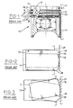
- the upper ring 11 (commonly called the top compression ring) is located approximately 5-6 millimetres below the piston crown 12 within a groove 13; the piston surface from the crown 12 to the top groove 13 is generally known as the top land 14.
- the axial clearance between the groove 13 and the ring 11 is around 40-50 microns (.002 inches).
- the clearance 17 between the top land 14 and the cylinder bore wall 16 is designed to prevent interference during cold starts or other conditions that induce rapid expansion of the piston crown ahead of the cylinder bore.
- the ring face 18 (the surface riding on the cylinder bore surface 16 and oil film 14) is of a barrel profile to promote rapid hydrodynamic film formation and easy glide during both upward as well as downward piston travel.
- the second ring 20 (also commonly called a scraper or second compression ring) is located in the second groove 21; the second groove 21 is located 4-5 millimetres below the top groove 13.
- the piston outer surface between the top ring 11 and the second ring 20 is referred to as the second land or middle land 22 (in the case of gasoline or spark ignition engines the ring pack usually consists of three rings, or four or more rings for diesel engines).
- the face 23 of the second ring face can be a tapered wedge profile, slightly rounded at the lower edge; this rounding facilitates scraping off the oil layer during the piston downward travel without incurring excessive friction losses. It also serves to scrape off the excessive oil to maintain a thin oil film.
- the ring-groove clearance is usually around 50 microns (.002 inches).
- the third ring 24 is the oil control ring, designed to maintain an oil film on the bore surface while scraping off and returning any excess oil to the sump.
- crevice volume is defined as remote spaces of the combustion chamber which trap the gas mixture charge during the compression stroke and effectively isolate the trapped charge from flame and thereby combustion. This trapped charge is released into the combustion chamber during the expansion stroke and is expelled along with the combustion products.
- the largest single constituent of crevice volume is the piston assembly. More specifically, this includes the top and second ring clearance volumes 29,30, and the piston land-bore annuli volumes 25,26 generated by the top and second ring lands.
- blow-by A significant part of blow-by results from the gas flow behind the rings through the ring-groove clearances. Blow-by is that portion of the gas mixture of the combustion chamber (mainly the charge during the compression stroke and the combustion products after ignition and during expansion strokes) that flow past the ring pack into the oil sump.
- Two adverse consequences of blow-by are (i) loss of engine power and fuel economy (normal blow-by is around .75-1% of the volume of the change ), and (ii) the boiling of oil due to contamination with acidified oil and contamination from combustion products.
- the rings Due to the large ring-groove clearance (29,30), the rings are permitted axial ring twist as shown in Figure 3.
- the twisting action also eventually wears away the corners (such as 27,28 of groove 13) during piston strokes.
- the twisting or ring flutter generates a pounding action and causes wear at the groove edges 27,28. This enhances peristaltic pumping action and increases oil consumption, hydrocarbon emissions and blow-by.
- the combustion gases can fill the crevice volume behind the rings 11,20 and during the compression stroke, can escape by being pumped past the rings into the crankcase. Conversely, the oil can migrate behind the rings in the groove during the exhaust stroke and be pumped upwards into the combustion chamber.
- each seal element 34 provides a piston assembly 36 that has, for each groove 31, radially outer regions 32,33 and for each seal element 34 has radially outer surface portions 35,37 of the side walls 39,40, all contoured with substantially tractrix surfaces.
- the tractrix mathematical relationship is one where a curve 41 is described by the locus of one end P of a tangent line 42 (of length L) as the other end Q is moved along the X axis. As the X coordinate exceeds the length of the tangent line, the curve becomes asymptotic to the X axis.
- the crown surface 43 of the seal element may also have essentially mirror image tractrix surfaces 43a,43b, one in the upper half and one in the lower half of the crown surface. Each tractrix surface can rotate or translate and still maintain contact with the other tractrix surface.
- X L cosh -1 (L/Y) - ⁇ (L 2 -Y 2 )
- the length of the tangent line is multiplied by the inverse hyperbole of the cosine of the length over Y less the square root of length squared minus y squared.
- X L cosh -1 (L/Y) - ⁇ (L 2 -Y 2 )
- the length of the tangent line is multiplied by the inverse hyperbole of the cosine of the length over Y less the square root of length squared minus y squared.
- the height of the groove influences the choice of Y intercept for the shoulders 43a and 43b of the element crown 43. It is desirable to merge or integrate the shoulders 43a, 43b with no straight or connecting surface therebetween.
- the reaction contact points A and B of the groove shoulders with the element side surfaces 35,37 form a triangle 52 with the load contact point C of the crown 43 on the film of the bore wall 47.
- the triangle will shift (see broken line triangle) and contacts will move to A', B' and C'.
- the load contact point will consistently stay at the bore wall allowing at most only about 0.0005 cm (0.0002 inch) spacing between the sealing element and bore wall. This permits a squeeze film of fluid (gas or oil) to reside therebetween enhancing the friction reduced sliding contact with the bore wall without allowing blow-by.
- the sealing assembly of this invention has a piston 45 with a side wall 46 moveable closely along a bore wall 47 with a controlled squeeze film gap 48 therebetween.
- the assembly defines surfaces in at least one of the bore wall 47 or piston 45 to form a groove 31 facing the other of the piston or bore wall, the groove having its outer radial regions 32,33 of the surfaces smoothly curved to form a pair of oppositely facing shoulders.
- the assembly further has a sealing element 34 with (i) smoothly curved side surfaces 35,37 mateable with the groove shoulders for supporting the element in the groove and (ii) a curved crown surface effective to tangentially contact the cylinder bore wall 47 while the side surfaces 35,37 each tangentially contact their respective mating groove shoulders 32,33.
- the pair of mating groove shoulders 32,33 and element side walls 35,37 each have defined curvatures as indicated above that are effective to maintain tangency and transfer any load in the element, resulting from the crown-cylinder bore wall contact, to the shoulders in a substantially equal manner regardless of articulation of the element with respect to the groove.
- the load at the contact points is virtually the same throughout because of the tractrix relationship and behaviour.
- the seal assembly may further incorporate a hollowing of the sealing element 34 at its base or root 55 and insertion of an elastomeric ring 56 into the hollow cavity 57 to exert a resilient pressure between the root 58 of the groove 31 and the walls of cavity 57.
- the elastomeric ring (that fills the hollow ring and groove space) should have a resilient compressibility of about 20% when installed; the elastomeric material should be stable up to a temperature of 300°F or higher. To prevent the material from rising above such temperature, means for splashing oil or other heat removing medium on the interior of the piston (proximate to the groove for the sealing element).
- the elastomeric ring will assist the inherent element tension to maintain contact [within 0.0005 cm (0,0002 inches)] with the bore wall even under extreme low or high temperature conditions.
- the hollowness of the ring promotes or defines thin flexible element flanges 59,60 which, as urged by the memory of the elastomeric material, flex the flanges to maintain contact with the shoulders 32,33 (an axial deflection vector).
- the piston, tractrix sealing element and bore wall are fabricated of a similar lightweight metal, such as aluminium. Thermal growth of each of such components will thus be essentially the same thereby enhancing the ability of the sealing element to maintain a friction reducing squeeze film along the bore wall.
- the sealing element is desirably an extruded aluminium alloy having a solid film lubricant coating impregnated into a prepared dimpled surface of such element. Extrudability facilitates making a hollow ring to receive the precompressed elastomer therein.
- the ring could be a soft steel that is continuously formed with a hollow shape by bellows expansion techniques where a charge is progressively exploded to form the metal strip to a continuous die.
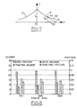
- Figure 8 shows the friction and blow-by using a conventional piston ring (commercially used in Ford Motor Company 1.9L-CUH engines) as the base, at different engine speeds.
- Figure 8 shows the friction and blow-by results of a piston assembly using the tractrix surfaces of this invention at various engine speeds for the same type of piston assembly. The comparison demonstrates friction is reduced from about .14 to .03-.045 and blow-by is reduced from 14-17 cubic centimetres to about 10-13 cubic centimetres.
Landscapes
- Engineering & Computer Science (AREA)
- General Engineering & Computer Science (AREA)
- Mechanical Engineering (AREA)
- Pistons, Piston Rings, And Cylinders (AREA)
Description
Claims (10)
- A sealing assembly for a cylinder bore wall having a piston (45) moveable closely along such wall (47) with a controlled gap therebetween, the assembly comprising:characterised in that (c) said pair of mating groove shoulders (32,33) and element side surfaces (35,37) each having defined curvatures effective to maintain tangency in the sense that the seal element is capable of articulating within said groove while said element side surfaces each tangentially contacts their respective mating groove surface and said curved crown surface maintains contact with the cylinder bore wall, so that any load imposed on the seal element (34) resulting from the crown-cylinder bore wall contact is transferred to the shoulders in a substantially equal manner regardless of articulation of the element (34) in said groove (31).(a) walls, in at least one of said cylinder bore wall (47) and piston (45), defining an annular groove (31) facing the other of said cylinder bore wall or piston, the outer radial regions (32,33) of said groove (31) being smoothly curved to form a pair of oppositely facing and diverging convex shoulders;(b) an annular sealing element (34) positioned in said groove (31) and having (i) smoothly curved and diverging concave side surfaces (35,37) mateable with said groove shoulders for supporting said element (34) in said groove (31) and (ii) a curved crown surface (43) effective to tangentially contact said cylinder bore wall (47)
- An assembly as claimed in claim 1, in which said defined curvatures are described, in X-Y coordinates, by one end point of a tangent line to the curvature as the other end of the tangent line is moved along the X axis.
- An assembly as claimed in claim 1, in which the curvature of said shoulders and element side surfaces adheres to a tractrix relationship whereby the tangential contact of a mating groove shoulder and element sidewall is free to shift along said define curvature as the element articulates.
- An assembly as claimed in any one of the preceding claims, in which said assembly has at least three of said sealing elements (34) and said grooves (31).
- An assembly as claimed in any one of the preceding claims, in which each of said shoulders and element side surfaces are coated with a thin film of solid lubricant in a polymer carrier.
- An assembly as claimed in claim 5, in which said solid film lubricant is selected from the group consisting of boron nitride, graphite and molybdenum disulphide.
- , An assembly as claimed in any one of the preceding claims, which further comprises means (56) to bias the sealing element into tangential contact with the cylinder bore wall.
- An assembly as claimed in claim 7, in which said means comprises an elastomer ring (56) acting between the root (55) of the groove (31) and the sealing element to carry out said bias.
- An assembly as claimed in claim 8, in which said means comprises a hollow cavity in said sealing element (34) defining flexible side flanges (59,60) in the sealing element (34) effective to flex in a lateral direction relative to the cylinder bore wall.
- A method of making a sealing assembly for a cylinder bore wall having a piston moveable therealong as claimed in any one of claims 1 to 9, comprising:(a) forming an annular groove in at least one of said cylinder bore wall and piston by electron discharge machining to provide a porous groove surface and to contour the exposed convex shoulders along the groove with a radius varying in an axial direction according to the relationship X = L cosh -1(L/Y) - √(L2 - Y2), where X and Y are coordinates of a point along tractrix surfaces 43a and 43b and L is the length of the tangent line 42;(b) forming a metallic split overlapping sealing ring having a trapezoidal cross section;(c) machining the outwardly facing surface of the sealing ring to a curvature defined by a radius varying according to said relationship, and machining the sides of said sealing ring to have a concave curvature with a radius varying according to said relationship;(d) machining the surface of the bore by electron discharge machining;(e) coating the grooves, ring and cylinder bore wall with a solid film lubricant carried in a polymer; and(f) positioning an elastomer insert operable between the groove root and the sealing ring.
Applications Claiming Priority (2)
| Application Number | Priority Date | Filing Date | Title |
|---|---|---|---|
| US08/213,335 US5695199A (en) | 1994-03-14 | 1994-03-14 | Piston sealing assembly |
| US213335 | 1994-03-14 |
Publications (2)
| Publication Number | Publication Date |
|---|---|
| EP0672849A1 EP0672849A1 (en) | 1995-09-20 |
| EP0672849B1 true EP0672849B1 (en) | 2001-07-11 |
Family
ID=22794704
Family Applications (1)
| Application Number | Title | Priority Date | Filing Date |
|---|---|---|---|
| EP95301445A Expired - Lifetime EP0672849B1 (en) | 1994-03-14 | 1995-03-06 | Piston sealing assembly |
Country Status (4)
| Country | Link |
|---|---|
| US (1) | US5695199A (en) |
| EP (1) | EP0672849B1 (en) |
| CA (1) | CA2144356A1 (en) |
| DE (1) | DE69521639D1 (en) |
Families Citing this family (15)
| Publication number | Priority date | Publication date | Assignee | Title |
|---|---|---|---|---|
| DE19908542A1 (en) | 1999-02-27 | 2000-08-31 | Mahle Gmbh | Piston with at least one annular groove and at least one piston ring |
| JP2002115759A (en) * | 2000-10-05 | 2002-04-19 | Hino Motors Ltd | Pressure piston ring |
| US6685193B2 (en) * | 2001-08-30 | 2004-02-03 | Illinois Tool Works Inc. | Self lubricating, non-sealing piston ring for an internal combustion fastener driving tool |
| DE102006058945A1 (en) * | 2006-02-07 | 2007-08-23 | Schaeffler Kg | Sealing ring for e.g. roller bearing, has sealing surface configured in form of tractrix surface to lead uniform loading of sealing surface during operation of ring, and sealing and counter surfaces provided with sealing effect |
| JP5293914B2 (en) * | 2006-02-21 | 2013-09-18 | Nok株式会社 | Reciprocating sealing ring |
| DE102007045465A1 (en) * | 2007-09-24 | 2009-04-02 | Federal-Mogul Nürnberg GmbH | Piston with oil supply channel for hub bores |
| WO2009089078A1 (en) * | 2008-01-11 | 2009-07-16 | Mcvan Aerospace, Llc | Reciprocating combustion engine |
| US8267821B2 (en) * | 2009-07-15 | 2012-09-18 | Schaeffler Technologies AG & Co. KG | Mechanical tensioner with damping mechanism |
| US8701620B2 (en) * | 2009-12-09 | 2014-04-22 | EcoMotors, International | Seal assembly for an internal combustion engine |
| JP6273277B2 (en) * | 2012-08-08 | 2018-01-31 | ヘニー・ペニー・コーポレーションHenny Penny Corporation | Lip seal for cookware and cookware with lip seal |
| DE102014108973A1 (en) * | 2014-06-26 | 2015-12-31 | Federal-Mogul Burscheid Gmbh | piston ring |
| CN106662246B (en) | 2014-06-27 | 2018-09-14 | 株式会社理研 | Piston ring |
| DE102018122258B3 (en) * | 2018-09-12 | 2019-12-24 | Federal-Mogul Burscheid Gmbh | PISTON RING AND PISTON WITH INSIDE GROOVE SEALING |
| US11060403B2 (en) | 2019-06-19 | 2021-07-13 | Achates Power, Inc. | Piston combinations for opposed-piston engines |
| WO2021230909A1 (en) * | 2020-05-11 | 2021-11-18 | Danfoss A/S | Floating ring seal for refrigerant compressor |
Family Cites Families (20)
| Publication number | Priority date | Publication date | Assignee | Title |
|---|---|---|---|---|
| US1532937A (en) * | 1922-06-03 | 1925-04-07 | Dock J Peeler | Piston for internal-combustion motors |
| US1901199A (en) * | 1931-12-11 | 1933-03-14 | Lyman M King Jr | Piston and ring therefor |
| DE1110480B (en) * | 1957-07-01 | 1961-07-06 | Goetzewerke | Sealing of reciprocating or rotatable cylindrical machine parts, in particular pistons, that can move relative to one another |
| US3727927A (en) * | 1968-09-06 | 1973-04-17 | Int Harvester Co | Ring manufacture, productive of line contact seal |
| US3907310A (en) * | 1971-02-25 | 1975-09-23 | Gas Dev Corp | Floating seal construction |
| US3751047A (en) * | 1971-06-10 | 1973-08-07 | Gould Inc | Piston ring assembly |
| US3806139A (en) * | 1972-03-30 | 1974-04-23 | Nippon Piston Ring Co Ltd | Piston ring |
| DE2417045C3 (en) * | 1973-05-21 | 1979-05-23 | Ramsey Corp., Manchester, Mo. (V.St.A.) | Internal combustion engine piston with a sealing ring with a U-profile |
| US4123072A (en) * | 1977-03-18 | 1978-10-31 | Dana Corporation | Piston ring assembly and method of making same |
| DE2854662C2 (en) * | 1978-12-18 | 1983-08-25 | WOCO Franz-Josef Wolf & Co, 6483 Bad Soden-Salmünster | Sealing ring for finned tubes |
| US4289264A (en) * | 1979-03-23 | 1981-09-15 | The United States Of America As Represented By The Secretary Of The Air Force | Uniform load piston ring |
| US4350352A (en) * | 1981-07-24 | 1982-09-21 | Mack Trucks, Inc. | Piston ring and groove assemblies |
| GB2117868A (en) * | 1982-04-08 | 1983-10-19 | Ae Plc | Improved piston ring seal |
| US4438937A (en) * | 1982-12-06 | 1984-03-27 | Moriarty Maurice J | Piston ring |
| US4890849A (en) * | 1983-05-17 | 1990-01-02 | James Walker & Company Limited | Shaft seals |
| US4846051A (en) * | 1988-02-23 | 1989-07-11 | Ford Motor Company | Uncooled oilless internal combustion engine having uniform gas squeeze film lubrication |
| JPH02118177U (en) * | 1989-03-09 | 1990-09-21 | ||
| US5275422A (en) * | 1989-03-31 | 1994-01-04 | Leber Corporation | Sealing assembly |
| DE3940301A1 (en) * | 1989-12-06 | 1991-06-13 | Friedhelm Stecher | Piston ring with gas seal - has depressurised underside, with active contact surface and cylindrical surface |
| US5169159A (en) * | 1991-09-30 | 1992-12-08 | General Electric Company | Effective sealing device for engine flowpath |
-
1994
- 1994-03-14 US US08/213,335 patent/US5695199A/en not_active Expired - Lifetime
-
1995
- 1995-03-06 EP EP95301445A patent/EP0672849B1/en not_active Expired - Lifetime
- 1995-03-06 DE DE69521639T patent/DE69521639D1/en not_active Expired - Lifetime
- 1995-03-10 CA CA002144356A patent/CA2144356A1/en not_active Abandoned
Also Published As
| Publication number | Publication date |
|---|---|
| US5695199A (en) | 1997-12-09 |
| CA2144356A1 (en) | 1995-09-15 |
| DE69521639D1 (en) | 2001-08-16 |
| EP0672849A1 (en) | 1995-09-20 |
Similar Documents
| Publication | Publication Date | Title |
|---|---|---|
| US5695199A (en) | Piston sealing assembly | |
| US6357341B1 (en) | Piston of internal combustion engine | |
| EP2045488B1 (en) | Piston ring of reciprocating engine | |
| EP0672850B1 (en) | A piston and ring assembly | |
| US5490445A (en) | Ultra low device volume piston system | |
| US5430938A (en) | Method of making and using a piston ring assembly | |
| CA1084548A (en) | Piston ring assembly and method of making same | |
| US7506575B2 (en) | Piston | |
| KR102639899B1 (en) | Cryogenic piston ring | |
| CA1118650A (en) | Low-friction piston | |
| KR950007629B1 (en) | Pistons for reciprocating machines using compressed gas and machines equipped with said pistons | |
| US6065438A (en) | Continuous piston rings for an internal combustion engine | |
| US6196179B1 (en) | Internal combustion engine | |
| JPS6236147B2 (en) | ||
| US4235447A (en) | Low friction oil control piston ring | |
| EP3115654B1 (en) | Piston ring configured to reduce friction | |
| US4230027A (en) | Reciprocating piston | |
| JP7393567B2 (en) | compression ring | |
| JPH06185620A (en) | piston ring | |
| EP1943444B2 (en) | Piston | |
| US20170299056A1 (en) | Oil Ring for a Piston Assembly | |
| JPH08261325A (en) | Oil ring with expander | |
| KR100409572B1 (en) | Piston ring structure | |
| RU2121591C1 (en) | Piston of internal combustion engine | |
| US4540185A (en) | Gas-lubricated seal for sealing between a piston and a cylinder wall |
Legal Events
| Date | Code | Title | Description |
|---|---|---|---|
| PUAI | Public reference made under article 153(3) epc to a published international application that has entered the european phase |
Free format text: ORIGINAL CODE: 0009012 |
|
| AK | Designated contracting states |
Kind code of ref document: A1 Designated state(s): DE FR GB |
|
| 17P | Request for examination filed |
Effective date: 19960205 |
|
| 17Q | First examination report despatched |
Effective date: 19990201 |
|
| GRAG | Despatch of communication of intention to grant |
Free format text: ORIGINAL CODE: EPIDOS AGRA |
|
| GRAG | Despatch of communication of intention to grant |
Free format text: ORIGINAL CODE: EPIDOS AGRA |
|
| GRAH | Despatch of communication of intention to grant a patent |
Free format text: ORIGINAL CODE: EPIDOS IGRA |
|
| GRAH | Despatch of communication of intention to grant a patent |
Free format text: ORIGINAL CODE: EPIDOS IGRA |
|
| GRAA | (expected) grant |
Free format text: ORIGINAL CODE: 0009210 |
|
| AK | Designated contracting states |
Kind code of ref document: B1 Designated state(s): DE FR GB |
|
| PG25 | Lapsed in a contracting state [announced via postgrant information from national office to epo] |
Ref country code: FR Free format text: LAPSE BECAUSE OF FAILURE TO SUBMIT A TRANSLATION OF THE DESCRIPTION OR TO PAY THE FEE WITHIN THE PRESCRIBED TIME-LIMIT Effective date: 20010711 |
|
| REF | Corresponds to: |
Ref document number: 69521639 Country of ref document: DE Date of ref document: 20010816 |
|
| PG25 | Lapsed in a contracting state [announced via postgrant information from national office to epo] |
Ref country code: DE Free format text: LAPSE BECAUSE OF FAILURE TO SUBMIT A TRANSLATION OF THE DESCRIPTION OR TO PAY THE FEE WITHIN THE PRESCRIBED TIME-LIMIT Effective date: 20011012 |
|
| EN | Fr: translation not filed | ||
| REG | Reference to a national code |
Ref country code: GB Ref legal event code: IF02 |
|
| PG25 | Lapsed in a contracting state [announced via postgrant information from national office to epo] |
Ref country code: GB Free format text: LAPSE BECAUSE OF NON-PAYMENT OF DUE FEES Effective date: 20020306 |
|
| PLBE | No opposition filed within time limit |
Free format text: ORIGINAL CODE: 0009261 |
|
| STAA | Information on the status of an ep patent application or granted ep patent |
Free format text: STATUS: NO OPPOSITION FILED WITHIN TIME LIMIT |
|
| 26N | No opposition filed | ||
| GBPC | Gb: european patent ceased through non-payment of renewal fee |
Effective date: 20020306 |