EP0672014B1 - Method and apparatus for forming rolls from strips of compressible material - Google Patents
Method and apparatus for forming rolls from strips of compressible material Download PDFInfo
- Publication number
- EP0672014B1 EP0672014B1 EP94903434A EP94903434A EP0672014B1 EP 0672014 B1 EP0672014 B1 EP 0672014B1 EP 94903434 A EP94903434 A EP 94903434A EP 94903434 A EP94903434 A EP 94903434A EP 0672014 B1 EP0672014 B1 EP 0672014B1
- Authority
- EP
- European Patent Office
- Prior art keywords
- endless belt
- belt conveyor
- strip
- compressible material
- roll
- Prior art date
- Legal status (The legal status is an assumption and is not a legal conclusion. Google has not performed a legal analysis and makes no representation as to the accuracy of the status listed.)
- Expired - Lifetime
Links
- 239000000463 material Substances 0.000 title claims abstract description 77
- 238000000034 method Methods 0.000 title claims abstract description 18
- 230000006835 compression Effects 0.000 claims abstract description 114
- 238000007906 compression Methods 0.000 claims abstract description 114
- 238000004804 winding Methods 0.000 claims abstract description 83
- 230000001154 acute effect Effects 0.000 claims abstract description 6
- 238000011144 upstream manufacturing Methods 0.000 claims description 11
- 230000015572 biosynthetic process Effects 0.000 claims description 5
- 230000002452 interceptive effect Effects 0.000 claims 1
- 238000009413 insulation Methods 0.000 description 18
- 239000003365 glass fiber Substances 0.000 description 8
- 238000011084 recovery Methods 0.000 description 8
- 238000004519 manufacturing process Methods 0.000 description 4
- 238000004806 packaging method and process Methods 0.000 description 4
- 230000001133 acceleration Effects 0.000 description 1
- 230000002411 adverse Effects 0.000 description 1
- 230000000977 initiatory effect Effects 0.000 description 1
- 238000009434 installation Methods 0.000 description 1
- 239000002557 mineral fiber Substances 0.000 description 1
- 230000001105 regulatory effect Effects 0.000 description 1
Images

Classifications
-
- B—PERFORMING OPERATIONS; TRANSPORTING
- B65—CONVEYING; PACKING; STORING; HANDLING THIN OR FILAMENTARY MATERIAL
- B65H—HANDLING THIN OR FILAMENTARY MATERIAL, e.g. SHEETS, WEBS, CABLES
- B65H18/00—Winding webs
- B65H18/08—Web-winding mechanisms
- B65H18/14—Mechanisms in which power is applied to web roll, e.g. to effect continuous advancement of web
- B65H18/22—Mechanisms in which power is applied to web roll, e.g. to effect continuous advancement of web by friction band
-
- B—PERFORMING OPERATIONS; TRANSPORTING
- B65—CONVEYING; PACKING; STORING; HANDLING THIN OR FILAMENTARY MATERIAL
- B65B—MACHINES, APPARATUS OR DEVICES FOR, OR METHODS OF, PACKAGING ARTICLES OR MATERIALS; UNPACKING
- B65B63/00—Auxiliary devices, not otherwise provided for, for operating on articles or materials to be packaged
- B65B63/02—Auxiliary devices, not otherwise provided for, for operating on articles or materials to be packaged for compressing or compacting articles or materials prior to wrapping or insertion in containers or receptacles
- B65B63/024—Auxiliary devices, not otherwise provided for, for operating on articles or materials to be packaged for compressing or compacting articles or materials prior to wrapping or insertion in containers or receptacles for compressing by winding
-
- B—PERFORMING OPERATIONS; TRANSPORTING
- B65—CONVEYING; PACKING; STORING; HANDLING THIN OR FILAMENTARY MATERIAL
- B65B—MACHINES, APPARATUS OR DEVICES FOR, OR METHODS OF, PACKAGING ARTICLES OR MATERIALS; UNPACKING
- B65B63/00—Auxiliary devices, not otherwise provided for, for operating on articles or materials to be packaged
- B65B63/04—Auxiliary devices, not otherwise provided for, for operating on articles or materials to be packaged for folding or winding articles, e.g. gloves or stockings
-
- B—PERFORMING OPERATIONS; TRANSPORTING
- B65—CONVEYING; PACKING; STORING; HANDLING THIN OR FILAMENTARY MATERIAL
- B65H—HANDLING THIN OR FILAMENTARY MATERIAL, e.g. SHEETS, WEBS, CABLES
- B65H18/00—Winding webs
- B65H18/08—Web-winding mechanisms
- B65H18/26—Mechanisms for controlling contact pressure on winding-web package, e.g. for regulating the quantity of air between web layers
-
- B—PERFORMING OPERATIONS; TRANSPORTING
- B65—CONVEYING; PACKING; STORING; HANDLING THIN OR FILAMENTARY MATERIAL
- B65H—HANDLING THIN OR FILAMENTARY MATERIAL, e.g. SHEETS, WEBS, CABLES
- B65H2301/00—Handling processes for sheets or webs
- B65H2301/40—Type of handling process
- B65H2301/41—Winding, unwinding
- B65H2301/413—Supporting web roll
- B65H2301/4137—Supporting web roll on its outer circumference
- B65H2301/4138—Supporting web roll on its outer circumference belt arrangement
-
- B—PERFORMING OPERATIONS; TRANSPORTING
- B65—CONVEYING; PACKING; STORING; HANDLING THIN OR FILAMENTARY MATERIAL
- B65H—HANDLING THIN OR FILAMENTARY MATERIAL, e.g. SHEETS, WEBS, CABLES
- B65H2701/00—Handled material; Storage means
- B65H2701/10—Handled articles or webs
- B65H2701/17—Nature of material
- B65H2701/177—Fibrous or compressible material
-
- B—PERFORMING OPERATIONS; TRANSPORTING
- B65—CONVEYING; PACKING; STORING; HANDLING THIN OR FILAMENTARY MATERIAL
- B65H—HANDLING THIN OR FILAMENTARY MATERIAL, e.g. SHEETS, WEBS, CABLES
- B65H2701/00—Handled material; Storage means
- B65H2701/10—Handled articles or webs
- B65H2701/18—Form of handled article or web
- B65H2701/184—Wound packages
- B65H2701/1846—Parts concerned
-
- B—PERFORMING OPERATIONS; TRANSPORTING
- B65—CONVEYING; PACKING; STORING; HANDLING THIN OR FILAMENTARY MATERIAL
- B65H—HANDLING THIN OR FILAMENTARY MATERIAL, e.g. SHEETS, WEBS, CABLES
- B65H2701/00—Handled material; Storage means
- B65H2701/10—Handled articles or webs
- B65H2701/19—Specific article or web
- B65H2701/1922—Specific article or web for covering surfaces such as carpets, roads, roofs or walls
-
- Y—GENERAL TAGGING OF NEW TECHNOLOGICAL DEVELOPMENTS; GENERAL TAGGING OF CROSS-SECTIONAL TECHNOLOGIES SPANNING OVER SEVERAL SECTIONS OF THE IPC; TECHNICAL SUBJECTS COVERED BY FORMER USPC CROSS-REFERENCE ART COLLECTIONS [XRACs] AND DIGESTS
- Y10—TECHNICAL SUBJECTS COVERED BY FORMER USPC
- Y10S—TECHNICAL SUBJECTS COVERED BY FORMER USPC CROSS-REFERENCE ART COLLECTIONS [XRACs] AND DIGESTS
- Y10S242/00—Winding, tensioning, or guiding
- Y10S242/03—Coreless coilers
Definitions
- This invention relates to an apparatus according to the preamble of claim 1 and method as defined in the preamble of claim 6 for forming spiral wound rolls from strips of compressible material. The strips are wound under compression and tension to minimize the diameter of the rolls.
- felts of mineral fibers such as fine diameter glass fibers
- These glass fiber felts are low in density and comprise fine glass fibers which entrap air in dead air pockets to achieve the thermal and acoustical insulating properties desired.
- the market demand for increasingly greater thermal and acoustical insulation performance has resulted in the production of increasingly thicker strips of insulation felts to achieve the insulation properties desired.
- For shipping and handling purposes it is desirable to compress these felts and form the strips into rolls for packaging wherein the strips are greatly reduced in volume from their normal uncompressed state e.g. up to a 9 to 1 compression ratio.
- the formation of the spiral wound roll must be accomplished without the formation of a hard center core or the telescoping of the roll. If the center core is too tightly wound in an attempt to form a smaller diameter roll, the portion of the felt strip forming the core will be excessively damaged affecting its recovery and insulating properties. The smaller diameter roll must also be obtained without causing the roll to telescope at its center thereby making the roll unsuitable for packaging. It is also important to form a roll of such dimensions that when it is packaged, the roll can be further compressed in one direction to form a readily stackable package when turned on its side. The rolls are packaged in such a way that advertising and other information appears on the circumference of the packaged roll. If the package formed from the roll is too narrow, the packages of the rolled strip insulation will not be stable for stacking and will be less acceptable in the market place where it is desirable to show the advertising and other information appearing on the circumference of the package.
- the winding space is defined by three members: an infeed conveyor, an inclined conveyor and a compression roll.
- the outer layer of the felt strip being wound onto the roll can expand after it passes the compression roll and before it passes inside the trailing portion of the felt strip being fed into the winding space.
- the roll can telescope and/or have too hard a core which adversely affects the recovery of the strip of compressible material.
- strips of compressible material are wound into rolls by compressing the strips under a moveable compression member and feeding the strips into a loop formed by an endless belt.
- the roll formed on the winding machine has a hollow core.
- the strip of compressible material is wound into a larger diameter, larger volume roll, than would be formed if the hollow core were eliminated, thereby requiring greater storage and shipping space.
- the object of the present invention is to provide for a method and an apparatus of the generic kind avoiding the shortcomings of the prior art.
- the present invention shall avoid damage of the material of the strips while the latter are wound to rolls.
- the present invention is an improved method and apparatus for forming spiral wound rolls from strips of compressible glass fiber insulation or other compressible strip materials.
- a first endless belt conveyor delivers the strips of compressible material into a winding space.
- the strip of compressible strip material As the strip of compressible strip material enters the winding space, the strip is compressed by a compression and slider plate assembly to the desired thickness for the layers of strip material in the spiral roll.
- the leading portion of the strip of compressible material successively contacts: an inclined second endless belt conveyor, a compression roll and a third endless belt conveyor which, together with the first endless belt conveyor, define the winding space.
- the second endless belt conveyor extends upwardly in an upstream direction at an acute angle to the first endless belt conveyor. As the strip of compressible material contacts the second conveyor, the second conveyor starts to turn the strip of compressible material back upon itself to form the spiral roll. The second conveyor, in cooperation with the other conveyors and the compression roll, maintains the strip in tension and compression as the strip is wound.
- the strip of compressible material next contacts the compression roll which is located intermediate the first and second conveyors.
- the compression roll continues to turn the strip of compressible material back upon itself to form the core of the roll while cooperating with the conveyors to maintain the strip of compressible material in tension and compression.
- the strip of compressible material is engaged by the third endless belt conveyor which is located intermediate the compression roll and the first endless belt conveyor.
- the third endless belt conveyor in cooperation with the other conveyors and the compression roll, maintains the strip of compressible material in compression and tension during the remainder of the winding cycle.
- the third endless belt conveyor guides leading portions of the strip of compressible material inside trailing portions of the strips being fed into the winding space by the first endless belt conveyor to complete the spiral winding of each layer of strip material in the roll.
- the compression roll and the third endless belt conveyor and compression and slider plate assembly are moved in a generally upstream direction as the roll is formed to enlarge the winding space as the diameter of the spiral roll of compressible material increases.
- the movement is regulated to keep the compression roll and the third endless belt conveyor properly located relative to the roll to maintain the strip in tension and compression while it is being wound.
- the expansion of the strip of compressible material after the strip passes the compression roll is minimized.
- This arrangement has enabled strips of compressible material to be formed into rolls having diameters of 66 cm (26 inches) as compared with 76 cm (30 inches) when not using the arrangement.
- strips of compressible material wound in accordance with the present invention form a roll having a volume about 25% less than those wound in accordance with the previous method and apparatus and exhibit the same recovery as strips wound with the previous method and apparatus.
- the rolls do not telescope when wound to this diameter and the center core is not as tightly wrapped as with the previous method and apparatus so that the core exhibits better recovery.
- the rolls formed from the present invention When the rolls formed from the present invention are packaged, the rolls can be compressed in one direction to flatten out the roll and form a roll 48 cm (19 inches) by 71 cm (28 inches). This compares with a flattened roll formed by the previous method and apparatus which had dimensions of 36 cm (14 inches) by 91 cm (36 inches). Accordingly, when the rolls made by the present invention are packaged, the resultant package is much more stable when placed on its side for display or storage.
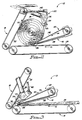
- FIG. 1 is a side elevation of the winding apparatus of the present invention as the winding of a roll is to be initiated.
- FIG. 2 is a side elevation of the winding apparatus of the invention as the winding of a roll is being completed.
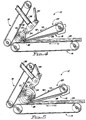
- FIG. 3 is a schematic side elevation view of the winding apparatus of the present invention as the winding of a roll is being initiated.
- FIG. 4 is a schematic side elevation view of the winding apparatus of the present invention about midway through the formation of a roll.
- FIG. 5 is a schematic side elevation view of the winding apparatus of the present invention as a roll is being completed.
- FIGS.1 and 2 the winding apparatus of the present invention is indicated at 12.
- the winding apparatus comprises a first endless belt conveyor 14, a compression and slider plate assembly 16, a second endless belt conveyor 18, a compression roll assembly 20 and a third endless belt conveyor 22.
- FIG. 1 illustrates the relative positions of the components of the winding apparatus 12 at the beginning of a winding cycle and
- FIG. 2 illustrates the relative positions of the components of the winding apparatus at the end of the winding cycle.
- the first endless belt conveyor has a substantially horizontal conveying surface 24 which conveys the strips of compressible material into a winding space defined by the first endless belt conveyor 14, the second endless belt conveyor 18, the compression roll assembly 20 and, after the core of the roll is formed, the third endless belt conveyor 22.
- the compression and slider plate assembly 16 Adjacent and above the conveying surface 24 is the compression and slider plate assembly 16.
- the compression and slider plate assembly 16 has a trailing portion 26 which extends substantially parallel to the conveying surface 24 of the conveyor 14.
- the compression and slider plate assembly has a leading portion 28 which extends upwardly from the trailing portion 26 in the upstream direction at an acute angle to the conveying surface 24 of the conveyor 14.
- the preferred angle of the leading portion 28 of the compression and slider plate assembly to the conveying surface 24 of the conveyor 14 is 14 degrees. However, the angle could be varied within certain limits determined by the amount of damage that can be tolerated in the product being wound. If the angle is too small, contact between the product and the compression and slider plate assembly 16 will cause excessive drag on the product and damage the product. If the angle is too large, the product may not feed smoothly under the compression and slider plate assembly 16. This would also cause excessive damage to the product.
- the compression and slider plate assembly 16 extends across the entire width of the production line having substantially the same width as the conveyor 14.
- the compression and slider plate assembly 16 is mounted on a frame 30 which moves parallel to the conveying surface 24 of the conveyor 14 as the roll of compressible strip material increases in diameter during the winding operation.
- the compression and slider plate assembly 16 is shown in its initial position for a winding cycle in FIG.1 and in its final position for a winding cycle in FIG.2.
- the second endless belt conveyor 18 is located at the downstream end of the first endless belt conveyor 14.
- the conveying surface 32 of the second endless belt conveyor 18 is the same width as conveying surface 24 and the conveying surface extends upwardly from the downstream end of the first conveyor 14 at an acute angle.
- the conveying surface of the second conveyor runs in an upward direction as shown in FIGS. 1 and 2.
- the angle of the conveying surface 32 of the second endless belt conveyor 18 to the conveying surface 24 of the first endless belt conveyor 14 is preferably 60 degrees.
- the angle between the conveying surfaces 32 and 24 could be varied from as little as 45 degrees to as much as 85 degrees and the winding apparatus 12 would still work.
- one purpose of the second endless belt conveyor 18 is to restrain the roll of compressible strip material being formed in the winding apparatus. Too low an angle would cause the roll being wound to move to far upstream in the winding space restricting the space for the third endless belt conveyor 22 and the compression and slider plate assembly 16. Too large an angle between the conveying surfaces 24 and 32 would cause the roll to lift out of the winding space as the velocity of the conveying surface 32 is greater than that of the conveying surface 24.
- the compression roll assembly 20 is located intermediate to the first endless belt conveyor 14 and the second endless belt conveyor 18.
- the compression roll assembly comprises a compression roll 34 which is substantially the same width as conveying surface 24 and is mounted on a frame 36 which is supported by pairs of arms 38 and 40. As shown in FIG. 1, the compression roll 34 rotates in a counter-clockwise direction.
- the conveying surface 24 of the first endless belt conveyor 14, the downstream end of portion 26 of the compression and slider plate assembly 16, the conveying surface of the second endless belt conveyor 18 and the compression roll 34 define the winding space at the initiation of the winding cycle.
- the outer layer of the roll is engaged by the third endless belt conveyor 22.
- FIG. 2 shows the location of the compression roll assembly at the end of the winding cycle.
- the compression roll 34 is moved from the position illustrated in FIG.1 to the position shown in FIG. 2, along a substantially straight line inclined at an angle of approximately 35 degrees to the conveying surface 24 of the first endless belt conveyor 14.
- the movement of the compression roll 34 during the winding operation in an upstream direction at an angle of 35 degrees to the conveying surface 24 maintains the compression roll properly positioned relative to the third endless belt conveyor 22.
- the third endless belt conveyor 22 is mounted on the compression and slider plate assembly frame 30 and moves with the compression and slider plate assembly in an upstream direction parallel to conveying surface 24 during the winding cycle.
- endless belt conveyors 14 and 18 are stationary.
- the compression roll assembly 20 and the compression and slider plate assembly 16 with the third endless belt conveyor 22 are moved upstream to enlarge the winding space as the roll increases in diameter.
- the third endless belt conveyor 22 is substantially the same width as the first endless belt conveyor 14. As shown in FIGS. 1 and 2, the third endless belt conveyor 22 moves in a counter-clockwise direction with the conveying surface 42 of the third endless belt conveyor in contact with the roll of compressible strip material causing the roll of compressible strip material to rotate in a clockwise direction.
- the positioning of the third endless belt conveyor intermediate the compression roll assembly 20 and the first endless belt conveyor 14 keeps the outer layer of the compressible strip material being wound onto the roll from expanding after it passes the compression roll 34 and before it passes inside a trailing portion of the strip material being fed into the winding space by the endless belt conveyor 14.
- the conveyor belt on the third endless conveyor 22 passes around a nosebar 44 at the downstream end of the conveyor.
- the use of the nosebar 44 rather than a roll enables the downstream end of the third conveyor to be positioned close to the compression roll 34, e.g. the nosebar can be about 13 mm (1/2 inch) in diameter by 3048 mm (120 inches) long.
- the third conveyor 22 tuck the portion of the strip of compressible material forming the outer layer of the roll tightly within the trailing portion of the strip of compressible material being fed into the winding space by the first conveyor 14.
- the positioning of the compression and slider plate assembly 16 between the third endless belt conveyor 22 and the strip of compressible material being fed into the winding space by the conveyor 14 keeps the return run of the conveyor 22 from contacting the upper surface of the portion of the strip of compressible material being fed into the winding space. This prevents the upper surface of the strip of compressible material from being damaged by the third endless belt conveyor 22.
- the first endless belt conveyor 14, the second endless belt conveyor 18, the compression roll 20 and the third endless belt conveyor 22 are all driven independently by conventional drives. With the drives for each of these components being separate, the velocities of the components can be independently set for optimum operation.
- the linear velocity (V2)of the second endless belt conveyor 18 is greater than the linear velocity (V1) of the first endless belt conveyor 14.
- the linear velocity (V3) of the compression roll 34 is greater than the linear velocity of the second endless belt conveyor 18.
- the linear velocity (V4) of the third endless belt conveyor 22 is greater than the linear velocity of the compression roll 34.
- the strip of compressible material which has a certain amount of drag exerted upon it by the compression and slider plate assembly 16 undergoes acceleration after it passes from beneath the compression and slider plate assembly 16 and is being wound onto the roll to keep the strip in tension and maintain the thickness of the strip constant during the winding operation.
- V2 is typically 105% to 110% of V1; V3 is typically 105% to 112% of V1; and V4 is typically 103% to 112% of V1.
- V2 is typically 108% to 115% of V1; V3 is typically 108% to 120% of V1; and V4 is typically 102% to 115% of V1.
- FIGS. 3, 4 and 5 schematically illustrate the winding process of the present invention.
- a strip of glass fiber insulation faced or unfaced and cut to a predetermined length, is fed longitudinally into the winding apparatus 12 from a production line which is not shown.
- the strip of glass fiber insulation is fed from the production line onto the endless belt conveyor 14 of the winding apparatus which feeds the strip into the winding space defined by the conveying surface 24 of conveyor 14, the downstream end of the trailing portion 26 of the compression and slider assembly 16, the conveying surface 32 of inclined conveyor 18 and the compression roll 34.
- the strip As the strip of insulation is fed beneath the compression and slider plate assembly 16, the strip is increasingly compressed by the leading portion 28 of the compression and slider plate assembly until the desired thickness for the strip is reached as defined by the spacing between the trailing portion 26 of the compression and slider plate assembly and the conveying surface 24 of the conveyor 14. As the compressed strip of insulation passes from beneath the trailing portion 26 of the compression and slider plate assembly into the winding space, the strip is contacted by the conveying surface 32 of the conveyor 18. The conveying surface 32, which is moving upward, begins to turn the strip back upon itself to form a spiral wound roll. The leading portion of the strip next contacts the compression roll 34 which turns the strip back upon itself to form the core of the spiral wound roll.
- the compression roll 34 is moved outwardly and the outer layer of the spiral wound roll is engaged by the third endless belt conveyor 22 as illustrated in FIG.4.
- the position of the conveying surface 42 of the third endless belt conveyor 22 relative to the compression roll 34 which is maintained throughout the winding cycle, prevents the strip of insulation from expanding after it passes the compression roll 34 and causes the leading portions of the strip to be tucked tightly inside the trailing portions of the strip being fed into the winding space by the first conveyor 14.
- the compression and slider plate assembly 16 and the third endless belt conveyor 22 are moved upstream to enlarge the winding space.
- the downstream end of the trailing portion 26 of the compression and slider plate assembly 16 is positioned at or slightly upstream from a line extending perpendicular to the conveying surface 24 of the first conveyor 14 and passing through the center of the spiral wound roll of insulation. This allows the insulation to flow smoothly into the roll from beneath the trailing portion 26 of the compression and slider plate assembly 16. If the downstream end of the trailing portion 26 is too far downstream of the roll center, the trailing portion 26 will cause the insulation passing from beneath the trailing portion into the roll to bulge out rather than smoothly passing into the roll. If the downstream end of the trailing portion 26 is too far upstream of the center of the roll, the insulation will re-expand before it reaches the roll nullifying the compression provided by the trailing portion 26 of the compression and slider plate assembly 16.
Landscapes
- Engineering & Computer Science (AREA)
- Mechanical Engineering (AREA)
- Winding Of Webs (AREA)
- Outside Dividers And Delivering Mechanisms For Harvesters (AREA)
- Registering, Tensioning, Guiding Webs, And Rollers Therefor (AREA)
- Press Drives And Press Lines (AREA)
Abstract
Description
- This invention relates to an apparatus according to the preamble of claim 1 and method as defined in the preamble of claim 6 for forming spiral wound rolls from strips of compressible material. The strips are wound under compression and tension to minimize the diameter of the rolls.
- In the insulation industry, felts of mineral fibers, such as fine diameter glass fibers, are formed into strips which are to be used for the thermal and/or acoustical insulation of buildings and other structures or apparatus. These glass fiber felts are low in density and comprise fine glass fibers which entrap air in dead air pockets to achieve the thermal and acoustical insulating properties desired. The market demand for increasingly greater thermal and acoustical insulation performance has resulted in the production of increasingly thicker strips of insulation felts to achieve the insulation properties desired. For shipping and handling purposes it is desirable to compress these felts and form the strips into rolls for packaging wherein the strips are greatly reduced in volume from their normal uncompressed state e.g. up to a 9 to 1 compression ratio. This reduction in volume saves on freight costs for the product and the resulting smaller diameter packages are easier to handle during shipment and at the job site. However, for insulating purposes, it is important that the strips of insulation recover to substantially their original thickness when released from the packages to thereby retain their insulating properties.
- It has been found that the repeated compression, expansion and recompression of these strips of glass fiber felts in the winding and packaging operation damages the felts so that the felts do not recover as fully. Thus, in a winding and packaging operation where the strips are allowed to expand even partially after their initial compression, the recovery will be affected and to obtain a smaller diameter roll with good recovery, it is necessary to minimize any expansion of the strips of felt once the strips have been initially compressed. Otherwise, to retain the desired recovery and insulating properties for the strips, it is necessary to form larger diameter rolls thereby increasing freight costs, requiring more storage space for the product and making the product harder to handle prior to installation.
- The formation of the spiral wound roll must be accomplished without the formation of a hard center core or the telescoping of the roll. If the center core is too tightly wound in an attempt to form a smaller diameter roll, the portion of the felt strip forming the core will be excessively damaged affecting its recovery and insulating properties. The smaller diameter roll must also be obtained without causing the roll to telescope at its center thereby making the roll unsuitable for packaging. It is also important to form a roll of such dimensions that when it is packaged, the roll can be further compressed in one direction to form a readily stackable package when turned on its side. The rolls are packaged in such a way that advertising and other information appears on the circumference of the packaged roll. If the package formed from the roll is too narrow, the packages of the rolled strip insulation will not be stable for stacking and will be less acceptable in the market place where it is desirable to show the advertising and other information appearing on the circumference of the package.
- In the winding machines of the prior art such as the winding machine shown and described in U.S. Patent 4,928,898, the winding space is defined by three members: an infeed conveyor, an inclined conveyor and a compression roll. With this arrangement, the outer layer of the felt strip being wound onto the roll can expand after it passes the compression roll and before it passes inside the trailing portion of the felt strip being fed into the winding space. This results in an additional expansion and recompression of the felt strip which causes damage to the glass fibers in the strip and requires the formation of a larger diameter roll, if the strip is to exhibit proper recovery, than would be required if the additional expansion and recompression were eliminated or minimized. In addition, should an attempt be made to wind a roll too small in diameter with such equipment, the roll can telescope and/or have too hard a core which adversely affects the recovery of the strip of compressible material.
- In another winding machine of prior art, shown and described in U.S. Patent No. 4,602,471, strips of compressible material are wound into rolls by compressing the strips under a moveable compression member and feeding the strips into a loop formed by an endless belt. As shown in Fig. 4 of this patent, the roll formed on the winding machine has a hollow core. Thus, the strip of compressible material is wound into a larger diameter, larger volume roll, than would be formed if the hollow core were eliminated, thereby requiring greater storage and shipping space.
- The object of the present invention is to provide for a method and an apparatus of the generic kind avoiding the shortcomings of the prior art. In particular the present invention shall avoid damage of the material of the strips while the latter are wound to rolls.
- This object is achieved by the method of claim 1 and the apparatus of claim 6 respectively. Accordingly, the present invention is an improved method and apparatus for forming spiral wound rolls from strips of compressible glass fiber insulation or other compressible strip materials. A first endless belt conveyor delivers the strips of compressible material into a winding space.
- As the strip of compressible strip material enters the winding space, the strip is compressed by a compression and slider plate assembly to the desired thickness for the layers of strip material in the spiral roll. The leading portion of the strip of compressible material successively contacts: an inclined second endless belt conveyor, a compression roll and a third endless belt conveyor which, together with the first endless belt conveyor, define the winding space.
- The second endless belt conveyor extends upwardly in an upstream direction at an acute angle to the first endless belt conveyor. As the strip of compressible material contacts the second conveyor, the second conveyor starts to turn the strip of compressible material back upon itself to form the spiral roll. The second conveyor, in cooperation with the other conveyors and the compression roll, maintains the strip in tension and compression as the strip is wound.
- The strip of compressible material next contacts the compression roll which is located intermediate the first and second conveyors. The compression roll continues to turn the strip of compressible material back upon itself to form the core of the roll while cooperating with the conveyors to maintain the strip of compressible material in tension and compression.
- After the core of the spiral wound roll is formed, the strip of compressible material is engaged by the third endless belt conveyor which is located intermediate the compression roll and the first endless belt conveyor. The third endless belt conveyor, in cooperation with the other conveyors and the compression roll, maintains the strip of compressible material in compression and tension during the remainder of the winding cycle. In addition, the third endless belt conveyor guides leading portions of the strip of compressible material inside trailing portions of the strips being fed into the winding space by the first endless belt conveyor to complete the spiral winding of each layer of strip material in the roll.
- The compression roll and the third endless belt conveyor and compression and slider plate assembly are moved in a generally upstream direction as the roll is formed to enlarge the winding space as the diameter of the spiral roll of compressible material increases. The movement is regulated to keep the compression roll and the third endless belt conveyor properly located relative to the roll to maintain the strip in tension and compression while it is being wound.
- With the addition of the third endless conveyor, intermediate the compression roll and the infeed conveyor and the outward movement of the compression roll in a substantially straight line rather than in a arc, the expansion of the strip of compressible material after the strip passes the compression roll is minimized. This arrangement has enabled strips of compressible material to be formed into rolls having diameters of 66 cm (26 inches) as compared with 76 cm (30 inches) when not using the arrangement. Thus, strips of compressible material wound in accordance with the present invention form a roll having a volume about 25% less than those wound in accordance with the previous method and apparatus and exhibit the same recovery as strips wound with the previous method and apparatus. Furthermore, the rolls do not telescope when wound to this diameter and the center core is not as tightly wrapped as with the previous method and apparatus so that the core exhibits better recovery.
- When the rolls formed from the present invention are packaged, the rolls can be compressed in one direction to flatten out the roll and form a roll 48 cm (19 inches) by 71 cm (28 inches). This compares with a flattened roll formed by the previous method and apparatus which had dimensions of 36 cm (14 inches) by 91 cm (36 inches). Accordingly, when the rolls made by the present invention are packaged, the resultant package is much more stable when placed on its side for display or storage.
- FIG. 1 is a side elevation of the winding apparatus of the present invention as the winding of a roll is to be initiated.
- FIG. 2 is a side elevation of the winding apparatus of the invention as the winding of a roll is being completed.
- FIG. 3 is a schematic side elevation view of the winding apparatus of the present invention as the winding of a roll is being initiated.
- FIG. 4 is a schematic side elevation view of the winding apparatus of the present invention about midway through the formation of a roll.
- FIG. 5 is a schematic side elevation view of the winding apparatus of the present invention as a roll is being completed.
- Referring to FIGS.1 and 2, the winding apparatus of the present invention is indicated at 12. The winding apparatus comprises a first
endless belt conveyor 14, a compression andslider plate assembly 16, a secondendless belt conveyor 18, acompression roll assembly 20 and a thirdendless belt conveyor 22. FIG. 1 illustrates the relative positions of the components of thewinding apparatus 12 at the beginning of a winding cycle and FIG. 2 illustrates the relative positions of the components of the winding apparatus at the end of the winding cycle. - As shown in FIGS. 1 and 2, the first endless belt conveyor has a substantially
horizontal conveying surface 24 which conveys the strips of compressible material into a winding space defined by the firstendless belt conveyor 14, the secondendless belt conveyor 18, thecompression roll assembly 20 and, after the core of the roll is formed, the thirdendless belt conveyor 22. - Adjacent and above the
conveying surface 24 is the compression andslider plate assembly 16. The compression andslider plate assembly 16 has atrailing portion 26 which extends substantially parallel to theconveying surface 24 of theconveyor 14. The compression and slider plate assembly has a leadingportion 28 which extends upwardly from thetrailing portion 26 in the upstream direction at an acute angle to theconveying surface 24 of theconveyor 14. - The preferred angle of the leading
portion 28 of the compression and slider plate assembly to the conveyingsurface 24 of theconveyor 14 is 14 degrees. However, the angle could be varied within certain limits determined by the amount of damage that can be tolerated in the product being wound. If the angle is too small, contact between the product and the compression andslider plate assembly 16 will cause excessive drag on the product and damage the product. If the angle is too large, the product may not feed smoothly under the compression andslider plate assembly 16. This would also cause excessive damage to the product. - The compression and
slider plate assembly 16 extends across the entire width of the production line having substantially the same width as theconveyor 14. The compression andslider plate assembly 16 is mounted on aframe 30 which moves parallel to the conveyingsurface 24 of theconveyor 14 as the roll of compressible strip material increases in diameter during the winding operation. The compression andslider plate assembly 16 is shown in its initial position for a winding cycle in FIG.1 and in its final position for a winding cycle in FIG.2. - The second
endless belt conveyor 18 is located at the downstream end of the firstendless belt conveyor 14. The conveyingsurface 32 of the secondendless belt conveyor 18 is the same width as conveyingsurface 24 and the conveying surface extends upwardly from the downstream end of thefirst conveyor 14 at an acute angle. The conveying surface of the second conveyor runs in an upward direction as shown in FIGS. 1 and 2. - The angle of the conveying
surface 32 of the secondendless belt conveyor 18 to the conveyingsurface 24 of the firstendless belt conveyor 14 is preferably 60 degrees. The angle between the conveyingsurfaces apparatus 12 would still work. However, one purpose of the secondendless belt conveyor 18 is to restrain the roll of compressible strip material being formed in the winding apparatus. Too low an angle would cause the roll being wound to move to far upstream in the winding space restricting the space for the thirdendless belt conveyor 22 and the compression andslider plate assembly 16. Too large an angle between the conveyingsurfaces surface 32 is greater than that of the conveyingsurface 24. - The
compression roll assembly 20 is located intermediate to the firstendless belt conveyor 14 and the secondendless belt conveyor 18. The compression roll assembly comprises acompression roll 34 which is substantially the same width as conveyingsurface 24 and is mounted on aframe 36 which is supported by pairs ofarms compression roll 34 rotates in a counter-clockwise direction. - As shown in FIG. 1, the conveying
surface 24 of the firstendless belt conveyor 14, the downstream end ofportion 26 of the compression andslider plate assembly 16, the conveying surface of the secondendless belt conveyor 18 and thecompression roll 34 define the winding space at the initiation of the winding cycle. After the core of the roll is formed, the outer layer of the roll is engaged by the thirdendless belt conveyor 22. - FIG. 2 shows the location of the compression roll assembly at the end of the winding cycle. With the use of the
support linkage arms compression roll 34 is moved from the position illustrated in FIG.1 to the position shown in FIG. 2, along a substantially straight line inclined at an angle of approximately 35 degrees to the conveyingsurface 24 of the firstendless belt conveyor 14. The movement of thecompression roll 34 during the winding operation in an upstream direction at an angle of 35 degrees to the conveyingsurface 24 maintains the compression roll properly positioned relative to the thirdendless belt conveyor 22. - As shown in FIGS. 1 and 2, the third
endless belt conveyor 22 is mounted on the compression and sliderplate assembly frame 30 and moves with the compression and slider plate assembly in an upstream direction parallel to conveyingsurface 24 during the winding cycle. During the winding cycle,endless belt conveyors compression roll assembly 20 and the compression andslider plate assembly 16 with the thirdendless belt conveyor 22 are moved upstream to enlarge the winding space as the roll increases in diameter. - The third
endless belt conveyor 22 is substantially the same width as the firstendless belt conveyor 14. As shown in FIGS. 1 and 2, the thirdendless belt conveyor 22 moves in a counter-clockwise direction with the conveyingsurface 42 of the third endless belt conveyor in contact with the roll of compressible strip material causing the roll of compressible strip material to rotate in a clockwise direction. The positioning of the third endless belt conveyor intermediate thecompression roll assembly 20 and the firstendless belt conveyor 14 keeps the outer layer of the compressible strip material being wound onto the roll from expanding after it passes thecompression roll 34 and before it passes inside a trailing portion of the strip material being fed into the winding space by theendless belt conveyor 14. - As shown in FIGS.1 and 2, the conveyor belt on the third
endless conveyor 22 passes around anosebar 44 at the downstream end of the conveyor. As shown in FIG.1, the use of thenosebar 44 rather than a roll enables the downstream end of the third conveyor to be positioned close to thecompression roll 34, e.g. the nosebar can be about 13 mm (1/2 inch) in diameter by 3048 mm (120 inches) long. This enables thethird conveyor 22 to tuck the portion of the strip of compressible material forming the outer layer of the roll tightly within the trailing portion of the strip of compressible material being fed into the winding space by thefirst conveyor 14. It also prevents the expansion of the strip of compressible material after it passes thecompression roll 34 and the resulting recompression of the strip as it is tucked inside the portion of the strip being fed into the winding space by theconveyor 14. With the use of the nosebar and the relatively short length of the conveyor when compared to its width, it is preferred to use sensors along each side of the conveyor belt to detect any tracking problems with the conveyor belt and continuously make any adjustments necessary to keep the conveyor belt on track. - The positioning of the compression and
slider plate assembly 16 between the thirdendless belt conveyor 22 and the strip of compressible material being fed into the winding space by theconveyor 14 keeps the return run of theconveyor 22 from contacting the upper surface of the portion of the strip of compressible material being fed into the winding space. This prevents the upper surface of the strip of compressible material from being damaged by the thirdendless belt conveyor 22. - The first
endless belt conveyor 14, the secondendless belt conveyor 18, thecompression roll 20 and the thirdendless belt conveyor 22 are all driven independently by conventional drives. With the drives for each of these components being separate, the velocities of the components can be independently set for optimum operation. In the preferred method of operation, the linear velocity (V2)of the secondendless belt conveyor 18 is greater than the linear velocity (V1) of the firstendless belt conveyor 14. The linear velocity (V3) of thecompression roll 34 is greater than the linear velocity of the secondendless belt conveyor 18. The linear velocity (V4) of the thirdendless belt conveyor 22 is greater than the linear velocity of thecompression roll 34. Thus, the strip of compressible material, which has a certain amount of drag exerted upon it by the compression andslider plate assembly 16 undergoes acceleration after it passes from beneath the compression andslider plate assembly 16 and is being wound onto the roll to keep the strip in tension and maintain the thickness of the strip constant during the winding operation. - As just mentioned, the velocities of the conveyors and the compression roll are adjusted for different products to keep the strip under tension and to minimize product damage. For faced products V2 is typically 105% to 110% of V1; V3 is typically 105% to 112% of V1; and V4 is typically 103% to 112% of V1. For unfaced products, V2 is typically 108% to 115% of V1; V3 is typically 108% to 120% of V1; and V4 is typically 102% to 115% of V1.
- FIGS. 3, 4 and 5 schematically illustrate the winding process of the present invention. As shown in FIG. 3, a strip of glass fiber insulation, faced or unfaced and cut to a predetermined length, is fed longitudinally into the winding
apparatus 12 from a production line which is not shown. The strip of glass fiber insulation is fed from the production line onto theendless belt conveyor 14 of the winding apparatus which feeds the strip into the winding space defined by the conveyingsurface 24 ofconveyor 14, the downstream end of the trailingportion 26 of the compression andslider assembly 16, the conveyingsurface 32 ofinclined conveyor 18 and thecompression roll 34. - As the strip of insulation is fed beneath the compression and
slider plate assembly 16, the strip is increasingly compressed by the leadingportion 28 of the compression and slider plate assembly until the desired thickness for the strip is reached as defined by the spacing between the trailingportion 26 of the compression and slider plate assembly and the conveyingsurface 24 of theconveyor 14. As the compressed strip of insulation passes from beneath the trailingportion 26 of the compression and slider plate assembly into the winding space, the strip is contacted by the conveyingsurface 32 of theconveyor 18. The conveyingsurface 32, which is moving upward, begins to turn the strip back upon itself to form a spiral wound roll. The leading portion of the strip next contacts thecompression roll 34 which turns the strip back upon itself to form the core of the spiral wound roll. - Once the core of the spiral wound roll is formed, the
compression roll 34 is moved outwardly and the outer layer of the spiral wound roll is engaged by the thirdendless belt conveyor 22 as illustrated in FIG.4. The position of the conveyingsurface 42 of the thirdendless belt conveyor 22 relative to thecompression roll 34, which is maintained throughout the winding cycle, prevents the strip of insulation from expanding after it passes thecompression roll 34 and causes the leading portions of the strip to be tucked tightly inside the trailing portions of the strip being fed into the winding space by thefirst conveyor 14. - As the spiral wound roll of insulation increases in diameter the
compression roll 34, the compression andslider plate assembly 16 and the thirdendless belt conveyor 22 are moved upstream to enlarge the winding space. As shown in FIGS. 3, 4 and 5, during the winding cycle, the downstream end of the trailingportion 26 of the compression andslider plate assembly 16 is positioned at or slightly upstream from a line extending perpendicular to the conveyingsurface 24 of thefirst conveyor 14 and passing through the center of the spiral wound roll of insulation. This allows the insulation to flow smoothly into the roll from beneath the trailingportion 26 of the compression andslider plate assembly 16. If the downstream end of the trailingportion 26 is too far downstream of the roll center, the trailingportion 26 will cause the insulation passing from beneath the trailing portion into the roll to bulge out rather than smoothly passing into the roll. If the downstream end of the trailingportion 26 is too far upstream of the center of the roll, the insulation will re-expand before it reaches the roll nullifying the compression provided by the trailingportion 26 of the compression andslider plate assembly 16.
Claims (16)
- A method for forming rolls from strips of compressible material by feeding a strip of compressible material to a winding space defined, in part, by a first driven, endless belt conveyor (14) which delivers the strip of compressible material to said winding space; a second driven, endless belt conveyor (18) extending upward at an acute angle from said first endless belt conveyor (14); and a driven compression roll (34) located intermediate said first driven, endless belt conveyor (14) and said second driven, endless belt conveyor (18); and by spirally winding the strip of compressible material into a roll, characterized in that:
the thickness of each layer of the strip of compressible material in the spirally wound roll is set by a compression and slider plate assembly (16) located above said first endless belt conveyor (14) as the strip of compressible material is fed into said winding space; the winding space is further defined by a third driven, endless belt conveyor (22) located intermediate said driven compression roll (34) and said first driven, endless belt conveyor (14); and the strip of compressible material is spirally wound into the roll by feeding the strip of compressible material from said first driven, endless belt conveyor (14) into successive contact with said second driven, endless belt conveyor (18), said driven compression roll (34), and said third driven, endless belt conveyor (22). - The method of claim 1, characterized in that: tension is applied to the strip of compressible material as the strip of compressible material is spirally wound into the roll.
- The method of claim 2, characterized in that: the tension is applied to the strip of compressible material by having the velocity of said second driven, endless belt conveyor (18) greater than the velocity of said first driven, endless belt conveyor (14); the velocity of said driven compression roll (34) greater than the velocity of said second driven, endless belt conveyor (18); and the velocity of said third driven, endless belt conveyor (22) greater than the velocity of said driven compression roll (34).
- The method of claim 1, characterized in that: said third driven, endless belt conveyor (22) guides a portion of the strip of compressible material forming the outer layer of the spirally wound roll inside a portion of the strip of compressible material being fed into said winding space by said first driven, endless belt conveyor (14).
- The method of claim 4, characterized in that: said third driven, endless belt conveyor (22) restricts the expansion of the outer layer of the spirally wound roll after the strip of compressible material passes said driven compression roll (34) and before the strip of compressible material passes inside the portion of the strip of compressible material being fed into said winding space by said first driven, endless belt conveyor (14).
- An apparatus for forming spirally wound rolls from strips of compressible material of the type comprising: a winding space within which spirally wound rolls are formed from strips of compressible material, said winding space being defined, in part, by a first endless belt conveyor (14), means for driving said first endless belt conveyor (14) to deliver the strips of compressible material to said winding space; a second endless belt conveyor (18), means for driving said second endless belt conveyor to cause the strips of compressible material to begin to turn in a spiral within said winding space; a compression roll (34) intermediate said first endless belt conveyor (14) and said second endless belt conveyor (18), means for driving said compression roll to cause the strips of compressible material to be turned further into the spiral within said winding space; characterized in that:said winding space is further defined by a third endless belt conveyor (22) having means for driving said third endless belt conveyor (22) to cause leading portions of the strips of compressible material to be tucked inside trailing portions of the strips of compressible material to complete the formation of each spiral layer of the spirally wound rolls within said winding space; anda compression and slider plate assembly (16) is located intermediate said third endless belt conveyor (22) and said first endless belt conveyor (14) to compress the strips of compressible material to a thickness substantially equal to the thickness of the compressible material in the spirally wound rolls and to prevent said third endless belt conveyor (22) from interfering with the delivery of the strips of compressible material to said winding space by said first endless belt conveyor (14).
- The apparatus of claim 6, characterized in that: said second endless belt conveyor (18) is driven at a velocity greater than the velocity of said first endless belt conveyor (14); said compression roll (34) is driven at a velocity greater than the velocity of said second endless belt conveyor (18); and said third endless belt conveyor (22) is driven at a velocity greater than the velocity of said compression roll (34) to maintain the strips of compressible material in tension as the strips of compressible material are being wound into the rolls.
- The apparatus of claim 7, characterized in that: said compression and slider plate assembly (16) is located relative to said first endless belt conveyor (14) to compress the strips of compressible material therebetween and to create a drag on the strips of compressible material to facilitate the tensioning of the strips of compressible material by said second endless belt conveyor (18), said compression roll (34) and said third endless belt conveyor (22) which are driven at higher velocities than said first endless belt conveyor (14).
- The apparatus of claim 8, characterized in that: means is provided for moving at least one of said first endless belt conveyor (14), said second endless belt conveyor (18), said compression roll (34) or said third endless belt conveyor (22) to enlarge said winding space as the spiral wound rolls of compressible material become greater in diameter during the winding process while maintaining the strips of compressible material in tension and compression.
- The apparatus of claim 9, characterized in that: said means for moving comprises a means (38, 40) for moving said compression roll (34) and a means (30) for moving said third endless belt conveyor (22) and said compression and slider plate assembly (16).
- The apparatus of claim 10, characterized in that: said means (38, 40) for moving said compression roll (34) moves said compression roll (34) outwardly from said first endless belt conveyor (14) and said second endless belt conveyor (18) in a substantially straight line.
- The apparatus of claim 10, characterized in that: said third endless belt conveyor (22) has a leading end which is in contact with the outer layer of said spirally wound roll of compressible material; and said means (30) for moving said third endless belt conveyor (22) and said compression and slider plate assembly (16) moves said third endless belt conveyor (22) and said compression and slider plate assembly (16) in a direction parallel to said first endless belt conveyor (14) to maintain a set spacing between said first endless belt conveyor (14) and said compression and slider plate assembly (16) as said spirally wound rolls grow in diameter and to maintain said leading end of said third endless belt conveyor (22) at or ahead of a line perpendicular to said first endless belt conveyor (14) and passing through the center of the spirally wound roll of compressible strip material being wound.
- The apparatus of claim 12, characterized in that: an endless belt of said third endless belt conveyor (22) passes around a nosebar (44) at the leading end of said third endless belt conveyor (22).
- The apparatus of claim 12, characterized in that: the acute angle between said first endless belt conveyor (14) and said second endless belt conveyor (18) is between 45° and 85°.
- The apparatus of claim 12, characterized in that: said means (38, 40) for moving said compression roll (34) moves said compression roll (34) outwardly from said first endless belt conveyor (14) and said second endless belt conveyor (18) in a substantially straight line at an angle of approximately 35° to the direction of travel of said first endless belt conveyor (14).
- The apparatus of claim 12, characterized in that: said compression and slider plate assembly (16) has a downstream product thickness setting portion (26) which extends parallel to the direction of travel of said first endless belt conveyor (14) and an upstream portion (28) which extends upwardly from the direction of travel of said first endless belt conveyor (14) at an angle of approximately 14°.
Applications Claiming Priority (3)
| Application Number | Priority Date | Filing Date | Title |
|---|---|---|---|
| US07/984,765 US5305963A (en) | 1992-12-03 | 1992-12-03 | Method and apparatus for forming rolls from strips of compressible material |
| US984765 | 1992-12-03 | ||
| PCT/US1993/011748 WO1994012417A1 (en) | 1992-12-03 | 1993-12-03 | Method and apparatus for forming rolls from strips of compressible material |
Publications (2)
| Publication Number | Publication Date |
|---|---|
| EP0672014A1 EP0672014A1 (en) | 1995-09-20 |
| EP0672014B1 true EP0672014B1 (en) | 1997-05-07 |
Family
ID=25530848
Family Applications (1)
| Application Number | Title | Priority Date | Filing Date |
|---|---|---|---|
| EP94903434A Expired - Lifetime EP0672014B1 (en) | 1992-12-03 | 1993-12-03 | Method and apparatus for forming rolls from strips of compressible material |
Country Status (7)
| Country | Link |
|---|---|
| US (1) | US5305963A (en) |
| EP (1) | EP0672014B1 (en) |
| AT (1) | ATE152694T1 (en) |
| AU (1) | AU5738694A (en) |
| DE (1) | DE69310542T2 (en) |
| ES (1) | ES2101496T3 (en) |
| WO (1) | WO1994012417A1 (en) |
Families Citing this family (21)
| Publication number | Priority date | Publication date | Assignee | Title |
|---|---|---|---|---|
| AU705679B2 (en) * | 1994-07-18 | 1999-05-27 | Strathayr Pty. Limited | Roll up tray |
| AUPM687394A0 (en) * | 1994-07-18 | 1994-08-11 | Strathayr Pty. Limited | Roll up tray |
| US5832696A (en) * | 1994-09-21 | 1998-11-10 | Owens Corning Fiberglas Technology, Inc. | Method and apparatus for packaging compressible insulation material |
| FR2731687B1 (en) * | 1995-03-17 | 1997-04-25 | Tictor Sa | REEL DEVICE FOR FORMING A COMPRESSED FIBROUS ROLL |
| FI100049B (en) * | 1995-06-14 | 1997-09-15 | Espe Oy | Method and apparatus for packaging open-cell cellular plastic |
| DE29604901U1 (en) * | 1996-03-16 | 1996-05-15 | Kaibel & Sieber GmbH, 67547 Worms | Device for winding a web of compressible material |
| ZA981514B (en) * | 1997-03-07 | 1998-08-28 | Saint Gobain Isover | Winding machine for fibrous mats |
| FR2809119A1 (en) * | 2000-05-17 | 2001-11-23 | Saint Gobain Isover | METHOD OF FORMING AND PACKAGING INSULATING FELTS AND ITS IMPLEMENTING DEVICE |
| US20040050988A1 (en) * | 2002-09-12 | 2004-03-18 | Kt Industries Llc | Method and apparatus for packing material under compression and the package made thereby |
| US7008588B2 (en) * | 2003-07-11 | 2006-03-07 | General Electric Company | Apparatus and method for forming panels from moldable material |
| US7100862B2 (en) * | 2003-09-03 | 2006-09-05 | Ottawa Fibre, Inc. | Roll-up machine and method |
| WO2006032154A1 (en) * | 2004-09-21 | 2006-03-30 | Strahm Textile Systems Ag | Device for uninterrupted winding of a continuously-fed textile material web |
| DE102007033794A1 (en) * | 2007-07-19 | 2009-01-22 | Saint-Gobain Isover G+H Ag | Method for producing a pipe shell made of mineral wool by a winding process as well as pipe shell produced therewith |
| WO2011005294A2 (en) * | 2009-06-23 | 2011-01-13 | Catbridge Machinery, Llc | Enveloper assembly for winding webs |
| RU2471699C1 (en) * | 2011-05-18 | 2013-01-10 | Государственное образовательное учреждение высшего профессионального образования "Ивановская государственная текстильная академия" (ИГТА) | Device to form cloth roll |
| FR2991301B1 (en) * | 2012-06-04 | 2014-05-23 | Saint Gobain Isover | ROLLER DEVICE |
| US9868605B2 (en) * | 2014-02-12 | 2018-01-16 | Andrew L. Bishop | Geotextile rolling apparatus |
| EP3115324A1 (en) * | 2015-07-06 | 2017-01-11 | Qubiqa Esbjerg A/S | A method and apparatus for making rolls from flexible material, such as mineral wool |
| US11045981B2 (en) | 2017-01-30 | 2021-06-29 | Ortho-Space Ltd. | Processing machine and methods for processing dip-molded articles |
| EP3753882B1 (en) | 2019-06-17 | 2022-04-27 | Handsaeme Machinery BVBA | Device and method for rolling strips of material |
| US11787655B2 (en) * | 2020-09-28 | 2023-10-17 | C3 Corporation | Variable roll cage machine and process |
Family Cites Families (10)
| Publication number | Priority date | Publication date | Assignee | Title |
|---|---|---|---|---|
| US2881984A (en) * | 1956-10-09 | 1959-04-14 | Charles P Dyken | Rolling machine |
| US3991538A (en) * | 1975-01-27 | 1976-11-16 | Owens-Corning Fiberglas Corporation | Packaging apparatus for compressible strips |
| US4164177A (en) * | 1978-09-07 | 1979-08-14 | Owens-Corning Fiberglas Corporation | Methods and apparatus for rolling material into a package |
| DE3128155A1 (en) * | 1981-07-16 | 1983-02-03 | Christian Maier GmbH & Co Maschinenfabrik, 7920 Heidenheim | Winding apparatus for web-like material for the production of winding rolls without a winding core |
| DE3314289C2 (en) * | 1983-04-20 | 1987-01-02 | Grünzweig + Hartmann und Glasfaser AG, 6700 Ludwigshafen | Method for wrapping a rotating bale of wrapping material, in particular of a laminated mineral fibre web, with a protective web for packaging, and device for carrying out the method |
| FR2553744B1 (en) * | 1983-10-21 | 1986-03-28 | Saint Gobain Isover | COMPRESSION COILER |
| US4602471A (en) * | 1985-05-28 | 1986-07-29 | Owens-Corning Fiberglas Corporation | Roll-up method and apparatus for mineral fiber pack |
| US4653397A (en) * | 1985-07-30 | 1987-03-31 | Owens-Corning Fiberglas Corporation | Apparatus for packaging insulation material |
| JPH0613380B2 (en) * | 1985-08-02 | 1994-02-23 | 産栄機設株式会社 | Winding compression method and device |
| FR2616137B1 (en) * | 1987-06-03 | 1990-08-03 | Saint Gobain Isover | IMPROVEMENTS ON COMPRESSION WINDING MACHINES OF COMPRESSIBLE MATERIALS |
-
1992
- 1992-12-03 US US07/984,765 patent/US5305963A/en not_active Expired - Lifetime
-
1993
- 1993-12-03 WO PCT/US1993/011748 patent/WO1994012417A1/en not_active Ceased
- 1993-12-03 AU AU57386/94A patent/AU5738694A/en not_active Abandoned
- 1993-12-03 AT AT94903434T patent/ATE152694T1/en not_active IP Right Cessation
- 1993-12-03 EP EP94903434A patent/EP0672014B1/en not_active Expired - Lifetime
- 1993-12-03 DE DE69310542T patent/DE69310542T2/en not_active Expired - Fee Related
- 1993-12-03 ES ES94903434T patent/ES2101496T3/en not_active Expired - Lifetime
Also Published As
| Publication number | Publication date |
|---|---|
| DE69310542D1 (en) | 1997-06-12 |
| US5305963A (en) | 1994-04-26 |
| EP0672014A1 (en) | 1995-09-20 |
| ATE152694T1 (en) | 1997-05-15 |
| WO1994012417A1 (en) | 1994-06-09 |
| ES2101496T3 (en) | 1997-07-01 |
| AU5738694A (en) | 1994-06-22 |
| DE69310542T2 (en) | 1997-11-27 |
Similar Documents
| Publication | Publication Date | Title |
|---|---|---|
| US5305963A (en) | Method and apparatus for forming rolls from strips of compressible material | |
| CN101062737B (en) | Winding machine for rolling thin sheet material on winding shaft and related winding method thereof | |
| US4494359A (en) | Method and apparatus for the long-term pressing of printed products especially newspapers | |
| CA2125744C (en) | Apparatus for winding stiffened coreless rolls and method | |
| HU214763B (en) | Apparatus for making roll from compressible strip of mineral fibers and roll making by it | |
| EP0978372A2 (en) | Method and apparatus for producing individual rolls of packing material | |
| PL302237A1 (en) | Method of and rewinding apparatus for winding up in coreless manner web materials into bales | |
| CA2158751A1 (en) | Rewinding machine and method for the formation of logs of web material with means for severing the web material | |
| FI104371B (en) | Apparatus for winding material webs, in particular paper or paperboard webs | |
| US6810643B1 (en) | Method of roll packing compressible materials | |
| CN1102393A (en) | A kind of winding method and its equipment | |
| US4550547A (en) | Method and apparatus for rolling and packaging convoluted foam pads | |
| US6321507B1 (en) | Apparatus for packaging insulation material | |
| CA1060417A (en) | Method and apparatus for forming convolute foam package | |
| US20080263997A1 (en) | Folding blade for insulation bagger | |
| US5240196A (en) | Cutting and feeding apparatus for webs of material on winding machines | |
| AU622728B2 (en) | Packing small mesh pieces | |
| CN210190680U (en) | Winding head device and rubber belt winding device | |
| CN108891966A (en) | A kind of coiler | |
| US20030024096A1 (en) | Method and device for producing reels consisting of a large number of flat objects | |
| CN115634960A (en) | Metal wire material receiving system | |
| CA2334778A1 (en) | Block formation system and method for controlling the folding of a block | |
| WO2025114485A1 (en) | A manufacturing device for manufacturing tobacco industry rods and a method of manufacturing tobacco industry rods | |
| EP0732991A1 (en) | Planar product of corrugated fibreboard and a method for its manufacture | |
| CA2708385C (en) | Foil roll with wound stiffening core, apparatus for winding the roll and method |
Legal Events
| Date | Code | Title | Description |
|---|---|---|---|
| PUAI | Public reference made under article 153(3) epc to a published international application that has entered the european phase |
Free format text: ORIGINAL CODE: 0009012 |
|
| 17P | Request for examination filed |
Effective date: 19950420 |
|
| AK | Designated contracting states |
Kind code of ref document: A1 Designated state(s): AT BE CH DE DK ES FR GB GR IE IT LI LU MC NL PT SE |
|
| RIN1 | Information on inventor provided before grant (corrected) |
Inventor name: TEAGUE, JO, MORGAN, III Inventor name: WEINSTEIN, LARRY, JOEL Inventor name: ALLWEIN, ROBERT, JOHN Inventor name: HARVEY, EMERSON, C., III |
|
| GRAG | Despatch of communication of intention to grant |
Free format text: ORIGINAL CODE: EPIDOS AGRA |
|
| 17Q | First examination report despatched |
Effective date: 19960820 |
|
| GRAH | Despatch of communication of intention to grant a patent |
Free format text: ORIGINAL CODE: EPIDOS IGRA |
|
| GRAH | Despatch of communication of intention to grant a patent |
Free format text: ORIGINAL CODE: EPIDOS IGRA |
|
| GRAA | (expected) grant |
Free format text: ORIGINAL CODE: 0009210 |
|
| AK | Designated contracting states |
Kind code of ref document: B1 Designated state(s): AT BE CH DE DK ES FR GB GR IE IT LI LU MC NL PT SE |
|
| PG25 | Lapsed in a contracting state [announced via postgrant information from national office to epo] |
Ref country code: NL Free format text: LAPSE BECAUSE OF FAILURE TO SUBMIT A TRANSLATION OF THE DESCRIPTION OR TO PAY THE FEE WITHIN THE PRESCRIBED TIME-LIMIT Effective date: 19970507 Ref country code: LI Effective date: 19970507 Ref country code: GR Free format text: LAPSE BECAUSE OF FAILURE TO SUBMIT A TRANSLATION OF THE DESCRIPTION OR TO PAY THE FEE WITHIN THE PRESCRIBED TIME-LIMIT Effective date: 19970507 Ref country code: DK Effective date: 19970507 Ref country code: CH Effective date: 19970507 |
|
| REF | Corresponds to: |
Ref document number: 152694 Country of ref document: AT Date of ref document: 19970515 Kind code of ref document: T |
|
| REG | Reference to a national code |
Ref country code: CH Ref legal event code: EP |
|
| ITF | It: translation for a ep patent filed | ||
| REF | Corresponds to: |
Ref document number: 69310542 Country of ref document: DE Date of ref document: 19970612 |
|
| REG | Reference to a national code |
Ref country code: ES Ref legal event code: FG2A Ref document number: 2101496 Country of ref document: ES Kind code of ref document: T3 |
|
| ET | Fr: translation filed | ||
| REG | Reference to a national code |
Ref country code: IE Ref legal event code: FG4D Free format text: 73833 |
|
| PG25 | Lapsed in a contracting state [announced via postgrant information from national office to epo] |
Ref country code: SE Effective date: 19970807 Ref country code: PT Effective date: 19970807 |
|
| NLV1 | Nl: lapsed or annulled due to failure to fulfill the requirements of art. 29p and 29m of the patents act | ||
| REG | Reference to a national code |
Ref country code: CH Ref legal event code: PL |
|
| PLBE | No opposition filed within time limit |
Free format text: ORIGINAL CODE: 0009261 |
|
| STAA | Information on the status of an ep patent application or granted ep patent |
Free format text: STATUS: NO OPPOSITION FILED WITHIN TIME LIMIT |
|
| 26N | No opposition filed | ||
| PGFP | Annual fee paid to national office [announced via postgrant information from national office to epo] |
Ref country code: IE Payment date: 19981207 Year of fee payment: 6 |
|
| PG25 | Lapsed in a contracting state [announced via postgrant information from national office to epo] |
Ref country code: IE Free format text: LAPSE BECAUSE OF NON-PAYMENT OF DUE FEES Effective date: 19991203 |
|
| REG | Reference to a national code |
Ref country code: IE Ref legal event code: MM4A |
|
| REG | Reference to a national code |
Ref country code: GB Ref legal event code: IF02 |
|
| PGFP | Annual fee paid to national office [announced via postgrant information from national office to epo] |
Ref country code: MC Payment date: 20061121 Year of fee payment: 14 Ref country code: AT Payment date: 20061121 Year of fee payment: 14 |
|
| PGFP | Annual fee paid to national office [announced via postgrant information from national office to epo] |
Ref country code: FR Payment date: 20061220 Year of fee payment: 14 |
|
| PGFP | Annual fee paid to national office [announced via postgrant information from national office to epo] |
Ref country code: GB Payment date: 20061222 Year of fee payment: 14 |
|
| PGFP | Annual fee paid to national office [announced via postgrant information from national office to epo] |
Ref country code: ES Payment date: 20061226 Year of fee payment: 14 |
|
| PGFP | Annual fee paid to national office [announced via postgrant information from national office to epo] |
Ref country code: IT Payment date: 20061231 Year of fee payment: 14 |
|
| PGFP | Annual fee paid to national office [announced via postgrant information from national office to epo] |
Ref country code: LU Payment date: 20070109 Year of fee payment: 14 |
|
| PGFP | Annual fee paid to national office [announced via postgrant information from national office to epo] |
Ref country code: DE Payment date: 20070131 Year of fee payment: 14 |
|
| PGFP | Annual fee paid to national office [announced via postgrant information from national office to epo] |
Ref country code: BE Payment date: 20070206 Year of fee payment: 14 |
|
| BERE | Be: lapsed |
Owner name: *SCHULLER INTERNATIONAL INC. Effective date: 20071231 |
|
| PG25 | Lapsed in a contracting state [announced via postgrant information from national office to epo] |
Ref country code: MC Free format text: LAPSE BECAUSE OF NON-PAYMENT OF DUE FEES Effective date: 20071231 |
|
| GBPC | Gb: european patent ceased through non-payment of renewal fee |
Effective date: 20071203 |
|
| PG25 | Lapsed in a contracting state [announced via postgrant information from national office to epo] |
Ref country code: AT Free format text: LAPSE BECAUSE OF NON-PAYMENT OF DUE FEES Effective date: 20071203 |
|
| PG25 | Lapsed in a contracting state [announced via postgrant information from national office to epo] |
Ref country code: BE Free format text: LAPSE BECAUSE OF NON-PAYMENT OF DUE FEES Effective date: 20071231 |
|
| PG25 | Lapsed in a contracting state [announced via postgrant information from national office to epo] |
Ref country code: DE Free format text: LAPSE BECAUSE OF NON-PAYMENT OF DUE FEES Effective date: 20080701 |
|
| REG | Reference to a national code |
Ref country code: FR Ref legal event code: ST Effective date: 20081020 |
|
| PG25 | Lapsed in a contracting state [announced via postgrant information from national office to epo] |
Ref country code: GB Free format text: LAPSE BECAUSE OF NON-PAYMENT OF DUE FEES Effective date: 20071203 |
|
| REG | Reference to a national code |
Ref country code: ES Ref legal event code: FD2A Effective date: 20071204 |
|
| PG25 | Lapsed in a contracting state [announced via postgrant information from national office to epo] |
Ref country code: FR Free format text: LAPSE BECAUSE OF NON-PAYMENT OF DUE FEES Effective date: 20071231 Ref country code: ES Free format text: LAPSE BECAUSE OF NON-PAYMENT OF DUE FEES Effective date: 20071204 |
|
| PG25 | Lapsed in a contracting state [announced via postgrant information from national office to epo] |
Ref country code: LU Free format text: LAPSE BECAUSE OF NON-PAYMENT OF DUE FEES Effective date: 20071203 Ref country code: IT Free format text: LAPSE BECAUSE OF NON-PAYMENT OF DUE FEES Effective date: 20071203 |