EP0671818A1 - Miniature receiver for reception of frequency or phase modulated RF signals - Google Patents
Miniature receiver for reception of frequency or phase modulated RF signals Download PDFInfo
- Publication number
- EP0671818A1 EP0671818A1 EP94810143A EP94810143A EP0671818A1 EP 0671818 A1 EP0671818 A1 EP 0671818A1 EP 94810143 A EP94810143 A EP 94810143A EP 94810143 A EP94810143 A EP 94810143A EP 0671818 A1 EP0671818 A1 EP 0671818A1
- Authority
- EP
- European Patent Office
- Prior art keywords
- receiver
- frequency
- receiver according
- low
- integrated circuit
- Prior art date
- Legal status (The legal status is an assumption and is not a legal conclusion. Google has not performed a legal analysis and makes no representation as to the accuracy of the status listed.)
- Granted
Links
Images


Classifications
-
- H—ELECTRICITY
- H04—ELECTRIC COMMUNICATION TECHNIQUE
- H04R—LOUDSPEAKERS, MICROPHONES, GRAMOPHONE PICK-UPS OR LIKE ACOUSTIC ELECTROMECHANICAL TRANSDUCERS; DEAF-AID SETS; PUBLIC ADDRESS SYSTEMS
- H04R25/00—Deaf-aid sets, i.e. electro-acoustic or electro-mechanical hearing aids; Electric tinnitus maskers providing an auditory perception
- H04R25/55—Deaf-aid sets, i.e. electro-acoustic or electro-mechanical hearing aids; Electric tinnitus maskers providing an auditory perception using an external connection, either wireless or wired
- H04R25/554—Deaf-aid sets, i.e. electro-acoustic or electro-mechanical hearing aids; Electric tinnitus maskers providing an auditory perception using an external connection, either wireless or wired using a wireless connection, e.g. between microphone and amplifier or using Tcoils
-
- H—ELECTRICITY
- H04—ELECTRIC COMMUNICATION TECHNIQUE
- H04B—TRANSMISSION
- H04B1/00—Details of transmission systems, not covered by a single one of groups H04B3/00 - H04B13/00; Details of transmission systems not characterised by the medium used for transmission
- H04B1/06—Receivers
- H04B1/16—Circuits
- H04B1/26—Circuits for superheterodyne receivers
- H04B1/28—Circuits for superheterodyne receivers the receiver comprising at least one semiconductor device having three or more electrodes
-
- H—ELECTRICITY
- H04—ELECTRIC COMMUNICATION TECHNIQUE
- H04R—LOUDSPEAKERS, MICROPHONES, GRAMOPHONE PICK-UPS OR LIKE ACOUSTIC ELECTROMECHANICAL TRANSDUCERS; DEAF-AID SETS; PUBLIC ADDRESS SYSTEMS
- H04R2225/00—Details of deaf aids covered by H04R25/00, not provided for in any of its subgroups
- H04R2225/51—Aspects of antennas or their circuitry in or for hearing aids
-
- H—ELECTRICITY
- H04—ELECTRIC COMMUNICATION TECHNIQUE
- H04R—LOUDSPEAKERS, MICROPHONES, GRAMOPHONE PICK-UPS OR LIKE ACOUSTIC ELECTROMECHANICAL TRANSDUCERS; DEAF-AID SETS; PUBLIC ADDRESS SYSTEMS
- H04R25/00—Deaf-aid sets, i.e. electro-acoustic or electro-mechanical hearing aids; Electric tinnitus maskers providing an auditory perception
- H04R25/55—Deaf-aid sets, i.e. electro-acoustic or electro-mechanical hearing aids; Electric tinnitus maskers providing an auditory perception using an external connection, either wireless or wired
- H04R25/556—External connectors, e.g. plugs or modules
Definitions
- the present invention relates to a miniature receiver for receiving a high-frequency frequency- or phase-modulated signal, the receiver determining at least the module oscillator, mixing stage, for mixing the high-frequency modulated signal supplied to the mixing stage with a signal generated by the oscillator and for generating an intermediate frequency signal is intermediate frequency part, demodulator and low-frequency amplifier, on which a low-frequency signal can be output, and an electrical source for supplying the above-mentioned modules with electrical energy is present.
- TDA 7000 an integrated circuit for producing a miniaturized receiver for receiving a high-frequency frequency-modulated signal has become known from the company Philips. Because of the required operating voltage of typically 4.5 volts and the relatively large current consumption of this integrated circuit of approximately 8 mA, this module is not suitable for building an extremely miniaturized FM receiver, because of the relatively large battery required. Furthermore, this also prevents the relatively large number of over 20 external components that are required to manufacture a receiver in addition to the integrated circuit. This is due in particular to the fact that the integrated circuit mentioned is constructed using pure bipolar technology. This technology practically excludes the possibility of integrating capacitors, which, among other things, does not allow the creation of fully integrated intermediate frequency filter arrangements and low frequency filters.
- the aim of the invention is to make a receiver of the type mentioned at the beginning so small build that he, with an energy source and an organ generating an acoustic signal, can be housed, for example, in the ear canal of a person.
- this object is achieved in that at least the modules oscillator, mixer, intermediate frequency filter arrangement, demodulator and low-frequency amplifier necessary for producing an FM receiver are contained in at most two integrated circuits and that the electrical energy source is a single-cell battery or a single-cell accumulator.
- CMOS technology This is because transistors with small threshold voltages and capacitors with relatively large capacities can be integrated with this technology.
- These advantages have been used to integrate modules that work in a low frequency range in this technology. By choosing a relatively low intermediate frequency (see further below) it has become possible to completely integrate the entire intermediate frequency part, including the intermediate frequency filter and intermediate frequency amplifier, without the presence of even a single external component.
- the modules that work in a high frequency range, such as high-frequency amplifiers, oscillators and mixers one integrates into bipolar technology.
- bipolar technology was chosen because components manufactured using CMOS technology are too slow for such applications. So that the higher threshold voltages of the transistors in bipolar technology do not have a disadvantageous effect, a voltage multiplier circuit has additionally been integrated in order to feed the modules created in bipolar technology with a higher operating voltage generated internally in the integrated circuit.
- a low-pass filter module and a muting or squelch module are preferably also present on the at most two integrated circuits.
- a preferred embodiment provides that all of the modules already mentioned, the functioning of which will be discussed further below, are contained in a single integrated circuit. This only integrated circuit is implemented in BiCMOS technology.
- a coil for forming a magnetically acting antenna is also assigned to the receiver. However, so that weaker signals can also be received, it is preferably provided to additionally couple an electrically acting wire, rod or coil antenna to the receiver.
- a preferred embodiment provides a switchable arrangement of the two antennas, in particular in the sense that when the electrically acting antenna is connected, the magnetically acting antenna becomes ineffective.
- the operating mode for receiving a high-frequency frequency-modulated or high-frequency phase-modulated signal can be adapted using a short-circuit bridge that can be used manually.
- the muting or squelch module monitors the size of the received amplified and demodulated signal. If this low-frequency signal is less than a certain predetermined value, the The bandwidth of the low-pass filter is reduced, which results in a better signal-to-noise ratio for small signals. If there is no low frequency signal or the low frequency signal is unusable, the low frequency amplifier is switched off.
- the number of additional external components required which are preferably all designed for surface mounting technology (SMD technology) is approximately half that of the input mentioned prior art have been reduced and that the operation of the receiver with a single hearing aid battery has become possible, a receiver volume has been reached, including all the above parts is less than 1 cm3.
- SMD technology surface mounting technology
- Such a receiver can be inserted into the ear canal of a person and is suitable, for example, in the event of a disaster, to coordinate individual disaster relief workers from one or more central offices, without the disaster relief workers having to carry a radio around and block a hand to operate the radio.
- a different type of use can, for example, be designed in such a way that a trainer directs his players' moves from the edge of the field during training or sporting events.
- hearing aids With hearing aids, it is known that, in addition to a microphone, they also have a so-called induction coil, it being possible to switch from microphone reception to induction coil reception by means of a switch.
- the main purpose of the induction coil reception is that a hearing aid wearer can follow certain occasions, for example church occasions, without the presence of disturbing environmental noises also recorded by the microphone.
- Laying induction loops in buildings is relatively complex and therefore rarely done. Disadvantageous is for the hearing aid wearer that he can hardly perceive the other people acoustically during the induction coil reception.
- the receiver according to the invention also opens up a new field of application here, namely when the receiver is designed in such a way that it can be coupled, for example, as an additive to a hearing aid. Functionally, the coupling must be both mechanical and electrical. However, it is not necessary for a receiver and a battery to be accommodated in the receiver add-on, since these parts are already present in the hearing aid. When using the receiver according to the invention, consideration is given above all to a hearing aid to be worn behind the ear or to hearing glasses.
- a receiver built as an addition to a hearing aid are available, for example, in schools for children with hearing loss and in the area of people wearing hearing aids. In schools for the hearing impaired, students can clearly and clearly hear the teacher.
- the receivers used up to now which correspond to the size of a cigarette box and which are worn around the waist and which are connected to the hearing aid of a student by means of cables, can be replaced. The student feels freer.
- the receiver add-on can be used to listen to the TV sound, the sound of the stereo system, the telephone or the bell. Small local transmitters are also required.
- the electrically-acting antenna already mentioned should preferably be able to be connected from the outside to the receiver accommodated in the housing.
- the magnetically acting antenna assigned to the receiver is switched off.
- a standby circuit is also preferably provided in the integrated circuit, which is only used as an additive when the receiver is used to a hearing aid. It allows the receiver to be switched on and off simultaneously with the hearing aid being switched on and off.
- connection points 16 which are denoted by a to r and which are connected to further components which are mounted on a circuit board which is not visible in this figure, preferably using SMD technology (surface-mounted device).
- the integrated circuit 11 is implemented in BiCMOS technology. Bipolar transistors in combination with integrated resistors and External inductors and capacitors are used to create circuits that process high frequencies. Transistors in CMOS technology are provided in order to implement the areas of the circuit which operate in a medium or low frequency range, for example the circuits for filtering and amplifying an intermediate frequency signal and a low frequency signal.
- CMOS technology also allows the integration of capacitors with a respectable capacitance per surface unit, which are suitable for producing both integrated RC filters and integrated filters with switched capacitors (switch capacitors).
- the integrated circuit 11 comprises a high-frequency amplifier 12, which is intended for preamplifying the high-frequency signal 1, which is received via an antenna 18, which is connected to the connection point a.
- the high-frequency amplifier 12 is designed as a selective amplifier.
- the means for frequency selection are available as external components.
- the pre-amplified and pre-filtered high-frequency signal 1 ' reaches a mixer stage 3.
- An oscillator signal 4 which is generated by a quartz-controlled oscillator 2, is also connected to this stage. To operate the oscillator, additional external components such as a quartz, coils and capacitors are necessary, which are connected to the connection points o, p, q and r.
- This signal 5 generated in the mixer has a frequency spectrum in the form of oscillator frequency ⁇ high-frequency signal, three times the oscillator frequency ⁇ high-frequency signal, five times the oscillator frequency ⁇ high-frequency signal, etc.
- This signal 5 is an intermediate frequency part 6, which intermediate frequency filter (RC filter) and intermediate frequency amplifier includes, supplied.
- RC filter intermediate frequency filter
- a selective amplification of the mixed product, oscillator frequency minus high-frequency signal, takes place in intermediate frequency part 6.
- This mixed product is referred to as intermediate frequency 5 '.
- the intermediate frequency part with its capacitors, resistors and transistors is fully integrable, it is necessary that it can be implemented in CMOS technology. Since transistors in this technology, as already mentioned in the introduction, are not suitable for higher frequencies, the oscillator frequency has been chosen so that the intermediate frequency signal only has a frequency that is between 15 and 50 kHz. The use of CMOS technology and the choice of the low intermediate frequency also has the advantage that the current consumption of the intermediate frequency part is extremely low.
- the receiver according to the invention is constructed as a superimposed receiver with a simple conversion of the received signal to the intermediate frequency signal with the very low selected intermediate frequency.
- the frequencies of the high-frequency signal intended for reception and the high-frequency signal with the image frequency are very close to one another.
- the reception of a high-frequency signal with the image frequency can be prevented on the one hand with a selectively designed high-frequency amplifier and on the other hand with a selective antenna.
- a complete rejection of the high-frequency signal with the image frequency has been dispensed with, because the choice of the very low intermediate frequency and the poor selectivity of the high-frequency amplifier mean that the circuit design focuses on the low power consumption and the smallest possible volume of the signal to be realized Receiver (few external components) have been placed.
- the distance between received user channels has been chosen to be large.
- the intermediate frequency signal 5 ' is fed to a demodulator 7, in which a low-frequency signal 9 is obtained from the intermediate frequency signal.
- This low-frequency signal 9 is fed to a low-pass filter arrangement 13, which comprises a low-pass filter 24 and has a sound correction element 25.
- the filtered and possibly sound-corrected low-frequency signal passes from the low-pass filter arrangement 13 to a low-frequency amplifier 8.
- This is designed as an output amplifier for the low-frequency signal, comprises a connection point I to which an externally adjustable resistor or a switchable resistor network for adjusting the volume can be connected.
- Three different types of outputs 26, 27, 28 of the output amplifier end at connection points h, i, k of the integrated circuit 11.
- an organ 19 for generating an acoustic signal for example an electromagnetic receiver, is described in detail later , connected to one of the three connection points mentioned.
- An amplified low-frequency signal 9 ′′ is fed to this receiver 19.
- the demodulator 7 also supplies a reference signal 20 for a muting or squelch module 14 which controls the low-pass filter 24 and the low-frequency amplifier 8 via connections 21, 22. If no high-frequency signal is received or if the signal-to-noise ratio of the low-frequency signal is too low, for example when reception is very weak, the low-frequency amplifier 14 is switched off via the connection 22.
- This function is well known as a squelch or squelch on FM receivers. In the present exemplary embodiment, the switch-off threshold of the squelch is fixed.
- a muting or noise attenuation function of the muting or squelch module 14 comes into effect, by means of which the connection width of the low-pass filter 24 is reduced via the connection 21 which increases the signal-to-noise ratio and improves the sensitivity of the receiver.
- the sound correction element 25 is connected to the two connection points n, m of the integrated circuit 11. If neither of the two connection points mentioned is connected to a circuit zero point, the reproduction curve of the sound correction element is flat. If the connection point n is connected to the circuit zero, which can be done, for example, with a jumper J1 or a similar means, such as an ordinary wire bridge, the sound correction element is given the function of a bandpass filter first Ranges with a lower cut-off frequency of approximately 200 Hz, which ensures correct reception of a phase-modulated signal. If the connection point n is open, the receiver is set to receive a frequency-modulated signal.
- the sound correction element has the function of a bandpass with cut-off frequencies at approximately 160 Hz and approximately 1,600 Hz, which allows the frequency response of a directional microphone of a hearing aid to be simulated. This is important when using the receiver as an addition to a hearing aid, since it can be achieved that the sound image of the hearing aid does not change if it receives a signal demodulated from the high-frequency signal via the directional microphone instead of acoustic signals. With a hearing aid that is equipped with a microphone without a pronounced directional characteristic, the reproduction curve of the microphone is flat.
- the frequency response of such a microphone can be simulated with the sound correction element 25 by disconnecting the connection m from the circuit zero.
- a voltage multiplier circuit 15, to which an external decoupling capacitor is connected via the connection point d, is provided to generate a higher voltage based on the voltage of a single-cell battery 10 or a single-cell accumulator 10 applied to the integrated circuit 11 between the connection points e, f in order to supply those modules of the integrated circuit that require a minimum operating voltage that is greater than 1 V (for example high-frequency amplifier 12) with electrical energy.
- a standby circuit 17 completes the integrated circuit 11 in the sense that a voltage applied at the connection point g is continuously monitored via a control signal connection 23. In the event of a low or no monitored voltage, the standby circuit 17 ensures that the receiver circuit is switched off, except for one of the standby circuit even extremely small residual current was consumed. When the monitored voltage reappears or becomes larger, the standby circuit 17 switches the receiver to normal operation.
- the supply voltage of a microphone from a hearing device can be considered as the monitored voltage, so that when the hearing device is switched off, the receiver according to the invention, which in this case is coupled to the hearing device, is switched to standby mode.
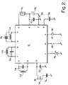
- FIG. 2 shows an electronic circuit with the previously described integrated circuit 11, which is suitable for realizing a complete FM receiver with a total volume of less than 1 cm 3. All external components shown in FIG. 2, such as capacitances Cn, inductances Ln, jumpers J1, J2, resistor R1, quartz Q1, battery B1 and receiver H1 are included in the volume mentioned.
- Such a miniature receiver if it is accommodated in a housing 33 (FIG. 3), can be worn invisibly in an auditory canal by people.
- a magnetically acting antenna 31 is connected to the connection point a of the integrated circuit 11.
- the antenna comprises a coil L1, one end of which is connected to the connection point a and the other end of which is connected in series with a capacitance C1, the other end of which is connected to the circuit zero point.
- a matching capacitor C2 is connected in parallel with the series circuit mentioned.
- the magnetically acting antenna 31 is adapted to a radio receiver that is worn in the ear canal of a person.
- the human body is an electrical conductor, on the surface of which the incident radio waves induce high-frequency currents, which in turn generate a high-frequency magnetic field immediately adjacent to the skin of the body, which is stronger than that which the incident waves themselves contain.
- the human body acts as a receiving antenna to which the magnetic antenna described above is coupled.
- the coil L2 and the capacitor C4, which represent a parallel resonant circuit, are integrated at the connection points b, c Switched circuit and are responsible for the selectivity of the high frequency amplifier.
- the coils L3, L4, the capacitance C5 and the quartz Q1 are connected to the oscillator circuit of the integrated circuit 11 via the connection points o, p, q and r and together with the latter generate the oscillator frequency already mentioned.
- the battery B1 is connected to the connection points e, f of the integrated circuit 11 via a switch S3. When the switch S3 is closed, a filter capacitor C7 is parallel to the battery B1.
- the connection point f of the integrated circuit which is connected to the negative pole of the battery when switch S3 is closed, forms the circuit zero point.
- connection point n which are connected to the sound correction element of the integrated circuit 11
- connection point n is connected to the circuit zero point by means 30, a wire bridge or the jumper J1.
- the variable resistor R1 which is present at connection point 1
- the connection point k is used to adjust the volume of the low-frequency signal output by the low-frequency amplifier at connection point k, which is made audible by the receiver H1, which is connected between the last-mentioned connection point and the positive pole of the battery.
- the connection point k at which one of the previously described three outputs of the low-frequency amplifier opens, has an output impedance which, for adapting the receiver H1, essentially corresponds to the impedance of the receiver H1.
- the capacitor C8 which is connected to the connection point d, is a decoupling capacitance for the voltage multiplier described above.
- FIG. 3 The structural design of a miniature receiver that can be worn in a person's ear canal can be seen essentially from FIG. 3.
- the largest elements within a housing 33 which essentially corresponds in shape and size to a housing of an in-the-ear hearing device, are the battery B1, the receiver H1 and one with the integrated circuit 11, the quartz Q1 and the other external components, of which only the coils L1 to L3 are visible, populated printed circuit board 34.
- this receiver could also be equipped with the aforementioned electrically acting antenna.
- connection points b, c, d, e, m, n, o, p, q and r correspond to those which have already been mentioned in the description of FIG. 2 and will not be described here described a second time.
- the receiver shown in this example when it is coupled to the hearing device 38, in this case a hearing device to be worn behind the ear, is supplied by the battery B1 arranged in the hearing device via electrically established connections.
- the battery is permanently switched on at the connection points e and f already described above, over which the filter capacity C7 lies.
- a connecting line between the hearing aid and the connection point g scans the screened microphone supply voltage of the hearing device and, in the event of an interrupted microphone supply voltage, ensures that the receiver is in standby mode.
- the receiver H1 which is likewise arranged in the hearing device 38, is connected via a coupling capacitance C6 and via a switch S2, either to the connection point h or to the connection point i of the integrated circuit 11.
- the two connection points, to each of which a low-frequency output of the previously described low-frequency amplifier is connected, differ in that the amplifier has a different output impedance.
- the hearing aid wearer By moving the switch S2 to one or the other position, the hearing aid wearer is given the prediction that the sound originating from the microphone of the hearing aid is attenuated compared to the sound received by the miniature receiver, or that in the other position the sound, which comes from the microphone, as well as the sound of the receiver are received at approximately the same volume.
- the magnetically acting antenna 31 described above can be switched to an electrically acting antenna 32, for example a wire, rod or coil antenna can be switched.
- FIG. 5 A constructive embodiment of a receiver designed as a hearing aid accessory can be seen from FIG. 5.
- the hearing aid accessory is accommodated in a separate housing 35 which can be detachably fastened to the housing 38 of the hearing aid by means of mechanical connecting means 36.
- the required electrical connections to the hearing aid are made via electrical connecting means 37, of which only a resilient pin, which makes contact with one pole of the battery, is visible in FIG. 5.
- the circuit board 34 is visible within the housing 35 of the receiver, on which only the quartz Q1, but not the integrated circuit and the other external components shown in FIG. 4, is drawn.
Landscapes
- Engineering & Computer Science (AREA)
- Computer Networks & Wireless Communication (AREA)
- Signal Processing (AREA)
- Otolaryngology (AREA)
- General Health & Medical Sciences (AREA)
- Neurosurgery (AREA)
- Health & Medical Sciences (AREA)
- Physics & Mathematics (AREA)
- Acoustics & Sound (AREA)
- Superheterodyne Receivers (AREA)
- Amplifiers (AREA)
- Circuits Of Receivers In General (AREA)
- Input Circuits Of Receivers And Coupling Of Receivers And Audio Equipment (AREA)
Abstract
Description
Die vorliegende Erfindung bezieht sich auf einen Miniaturempfänger zum Empfangen eines hochfrequenten frequenz- oder phasenmodulierten Signales, wobei der Empfänger wenigstens die Module Oszillator, Mischstufe, die zum Mischen des der Mischstufe zugeführten hochfrequenten modulierten Signales mit einem vom Oszillator erzeugten Signal und zum Generieren eines Zwischenfrequenzsignales bestimmt ist, Zwischenfrequenzteil, Demodulator sowie Niederfrequenzverstärker, an dem ein niederfrequentes Signal ausgebbar ist, umfasst und wobei eine elektrische Quelle zum Versorgen der obengenannten Module mit elektrischer Energie vorhanden ist.The present invention relates to a miniature receiver for receiving a high-frequency frequency- or phase-modulated signal, the receiver determining at least the module oscillator, mixing stage, for mixing the high-frequency modulated signal supplied to the mixing stage with a signal generated by the oscillator and for generating an intermediate frequency signal is intermediate frequency part, demodulator and low-frequency amplifier, on which a low-frequency signal can be output, and an electrical source for supplying the above-mentioned modules with electrical energy is present.
Mit der Bezeichnung TDA 7000 ist von der Firma Philips ein integrierter Schaltkreis zum Herstellen eines miniaturisierten Empfängers zum Empfangen eines hochfrequenten frequenzmodulierten Signales bekanntgeworden. Wegen der dazu geforderten Betriebsspannung von typisch 4,5 Volt und der relativ grossen Stromaufnahme dieses integrierten Schaltkreises von etwa 8 mA eignet sich dieser Baustein schon wegen der relativ grossen erforderlichen Batterie nicht dazu, einen extrem miniaturisierten FM-Empfänger zu bauen. Im weiteren verhindern dies auch die relativ grosse Zahl von über 20 externen Bauteilen, die zum Herstellen eines Empfängers zusätzlich zum integrierten Schaltkreis notwendig sind. Dies kommt insbesondere daher, dass der genannte integrierte Schaltkreis in reiner bipolarer Technologie aufgebaut ist. Diese Technologie schliesst die Möglichkeit, Kondensatoren zu integrieren, praktisch aus, wodurch unter anderem das Erstellen von vollständig integrierten Zwischenfrequenzfilteranordnungen und Niederfrequenzfilter nicht gegeben ist.With the designation TDA 7000, an integrated circuit for producing a miniaturized receiver for receiving a high-frequency frequency-modulated signal has become known from the company Philips. Because of the required operating voltage of typically 4.5 volts and the relatively large current consumption of this integrated circuit of approximately 8 mA, this module is not suitable for building an extremely miniaturized FM receiver, because of the relatively large battery required. Furthermore, this also prevents the relatively large number of over 20 external components that are required to manufacture a receiver in addition to the integrated circuit. This is due in particular to the fact that the integrated circuit mentioned is constructed using pure bipolar technology. This technology practically excludes the possibility of integrating capacitors, which, among other things, does not allow the creation of fully integrated intermediate frequency filter arrangements and low frequency filters.
Es ist deshalb die Aufgabe der vorliegenden Erfindung, zu versuchen, eine weitergehende Miniaturisierung bzw. eine extreme Miniaturisierung eines Empfängers zum Empfangen eines hochfrequenten frequenz- oder phasenmodulierten Signales zu erreichen, als dies mit der Verwendung des oben genannten integrierten Schaltkreises bisher möglich war. Das Ziel der Erfindung ist es, einen Empfänger der eingangs genannten Gattung derart klein zu bauen, dass er, mit einer Energiequelle und einem ein akustisches Signal erzeugenden Organ, beispielsweise im Gehörgang einer Person untergebracht werden kann.It is therefore the object of the present invention to attempt to achieve further miniaturization or extreme miniaturization of a receiver for receiving a high-frequency frequency- or phase-modulated signal than was previously possible with the use of the above-mentioned integrated circuit. The aim of the invention is to make a receiver of the type mentioned at the beginning so small build that he, with an energy source and an organ generating an acoustic signal, can be housed, for example, in the ear canal of a person.
Erfindungsgemäss wird diese Aufgabe dadurch gelöst, dass wenigstens die zum Herstellen eines FM-Empfängers notwendigen Module Oszillator, Mischstufe, Zwischenfrequenzfilteranordnung, Demodulator und Niederfrequenzverstärker in höchstens zwei integrierten Schaltkreisen enthalten sind und dass die elektrische Energiequelle eine einzellige Batterie oder ein einzelliger Akkumulator ist.According to the invention, this object is achieved in that at least the modules oscillator, mixer, intermediate frequency filter arrangement, demodulator and low-frequency amplifier necessary for producing an FM receiver are contained in at most two integrated circuits and that the electrical energy source is a single-cell battery or a single-cell accumulator.
Bei der Entwicklung der Schaltungen für die obengenannten Module und bei der Wahl der Integrationstechnologie für die einzelnen Module ist man davon ausgegangen, dass zum Betreiben der Module nur eine einzige Batterie- oder Akkumulatorenzelle notwendig ist, d.h., dass die Module mit einer Spannung von höchstens 1,8 V und mindestens 1,0 V betrieben werden können. Durch die Auslegung der Schaltungen zusätzlich in einer äusserst stromsparenden Technik hat man die Stromaufnahme des gesamten Empfängers in einen Bereich von etwa 1 mA reduzieren können. Die niedrige Betriebsspannung von typischerweise etwa 1,3 V und die kleine Stromaufnahme ermöglichen es, eine einzige Hörgerätebatterie zum Betreiben des Empfängers vorzusehen. Eine ausreichend lange Betriebsdauer des Empfängers für die weiter hinten genannten Anwendungen wird damit erreicht.When developing the circuits for the above-mentioned modules and choosing the integration technology for the individual modules, it was assumed that only one battery or accumulator cell is required to operate the modules, i.e. that the modules have a voltage of at most 1 , 8 V and at least 1.0 V can be operated. By designing the circuits additionally in an extremely energy-saving technology, it was possible to reduce the current consumption of the entire receiver to a range of approximately 1 mA. The low operating voltage of typically about 1.3 V and the small current consumption make it possible to provide a single hearing aid battery for operating the receiver. A sufficiently long operating time of the receiver for the applications mentioned below is thus achieved.
Mindestens ein Teil der Schaltungen der Empfängermodule ist in CMOS-Technologie ausgeführt worden. Dies, weil mit dieser Technologie Transistoren mit kleinen Schwellenspannungen und Kondensatoren mit relativ grossen Kapazitäten integrierbar sind. Diese Vorteile hat man genutzt, um vor allem Module, die in einem niedrigen Frequenzbereich arbeiten, in dieser Technologie zu integrieren. Durch die Wahl einer relativ tiefen Zwischenfrequenz (siehe weiter hinten) ist es möglich geworden, auch den gesamten Zwischenfrequenzteil, umfassend Zwischenfrequenzfilter und Zwischenfrequenzverstärker, ohne das Vorhandensein auch nur eines einzigen externen Bauelementes vollständig zu integrieren. Die in einem hohen Frequenzbereich arbeitenden Module, wie Hochfrequenzverstärker, Oszillator und Mischstufe, hat man in bipolarer Technologie integriert. Infolge der hohen in diesen Modulen zu verarbeitenden Frequenzen, die im vorliegenden Fall zwischen etwa 30 und etwa 200 MHz liegen, hat man die bipolare Technologie gewählt, weil Bauelemente, hergestellt in CMOS-Technik, für solche Anwendungen zu langsam sind. Damit sich die bei der bipolaren Technologie höheren Schwellenspannungen der Transistoren nicht nachteilig auswirken, ist zusätzlich eine Spannungsvervielfacherschaltung integriert worden, um die in bipolarer Technologie erstellten Module mit einer intern in der integrierten Schaltung erzeugten höheren Betriebsspannung zu speisen.At least some of the circuits of the receiver modules have been implemented using CMOS technology. This is because transistors with small threshold voltages and capacitors with relatively large capacities can be integrated with this technology. These advantages have been used to integrate modules that work in a low frequency range in this technology. By choosing a relatively low intermediate frequency (see further below) it has become possible to completely integrate the entire intermediate frequency part, including the intermediate frequency filter and intermediate frequency amplifier, without the presence of even a single external component. The modules that work in a high frequency range, such as high-frequency amplifiers, oscillators and mixers one integrates into bipolar technology. As a result of the high frequencies to be processed in these modules, which in the present case are between approximately 30 and approximately 200 MHz, bipolar technology was chosen because components manufactured using CMOS technology are too slow for such applications. So that the higher threshold voltages of the transistors in bipolar technology do not have a disadvantageous effect, a voltage multiplier circuit has additionally been integrated in order to feed the modules created in bipolar technology with a higher operating voltage generated internally in the integrated circuit.
Auf den höchstens zwei integrierten Schaltkreisen sind vorzugsweise ebenfalls ein Tiefpassfiltermodul und ein Muting- bzw. Squelchmodul vorhanden.A low-pass filter module and a muting or squelch module are preferably also present on the at most two integrated circuits.
Eine bevorzugte Ausführung sieht vor, dass sämtliche der bereits genannten Module, auf deren Funktionsweise weiter hinten eingegangen wird, in einer einzigen integrierten Schaltung enthalten sind. Diese einzige integrierte Schaltung ist in BiCMOS-Technik ausgeführt.A preferred embodiment provides that all of the modules already mentioned, the functioning of which will be discussed further below, are contained in a single integrated circuit. This only integrated circuit is implemented in BiCMOS technology.
Dem Empfänger zugeordnet ist ebenfalls eine Spule zum Bilden einer magnetisch wirkenden Antenne. Es ist vorzugsweise jedoch vorgesehen, damit auch schwächere Signale empfangen werden können, eine elektrisch wirkende Draht-, Stab- oder Spulenantenne zusätzlich an den Empfänger anzukoppeln. Eine bevorzugte Ausführung sieht eine umschaltbare Anordnung der beiden Antennen insbesondere in dem Sinne vor, dass beim Anschliessen der elektrisch wirkenden Antenne, die magnetisch wirkende Antenne unwirksam wird.A coil for forming a magnetically acting antenna is also assigned to the receiver. However, so that weaker signals can also be received, it is preferably provided to additionally couple an electrically acting wire, rod or coil antenna to the receiver. A preferred embodiment provides a switchable arrangement of the two antennas, in particular in the sense that when the electrically acting antenna is connected, the magnetically acting antenna becomes ineffective.
Das Anpassen der Betriebsart zum Empfangen eines hochfrequenten frequenzmodulierten oder hochfrequenten phasenmodulierten Signales kann mit einer manuell einsetzbaren Kurzschlussbrücke vollzogen werden.The operating mode for receiving a high-frequency frequency-modulated or high-frequency phase-modulated signal can be adapted using a short-circuit bridge that can be used manually.
Das Muting- oder Squelchmodul überwacht die Grösse des empfangenen verstärkten und demodulierten Signales. Ist dieses Niederfrequenzsignal kleiner als ein bestimmter vorgegebener Wert, wird automatisch die Bandbreite des Tiefpassfilters reduziert, wodurch sich für kleine Signale ein besseres Signal-Rausch-Verhältnis ergibt. Beim Fehlen oder bei einem unbrauchbar kleinen Niederfrequenzsignal wird der Niederfrequenzverstärker ausgeschaltet.The muting or squelch module monitors the size of the received amplified and demodulated signal. If this low-frequency signal is less than a certain predetermined value, the The bandwidth of the low-pass filter is reduced, which results in a better signal-to-noise ratio for small signals. If there is no low frequency signal or the low frequency signal is unusable, the low frequency amplifier is switched off.
Dank dem, dass es möglich geworden ist, einen extrem hohen Integrationsgrad für alle die vorgenannten Module zu erzielen, dass die Anzahl an zusätzlich benötigten externen Bauelementen, die vorzugsweise alle für Oberflächenmontagetechnik (SMD-Technik) ausgeführt sind, auf etwa die Hälfte gegenüber dem eingangs genannten Stand der Technik haben reduziert werden können und dass der Betrieb des Empfängers mit einer einzigen Hörgerätebatterie möglich geworden ist, hat man ein Empfängervolumen erreicht, das inklusive aller oben genannten Teile kleiner als 1 cm³ ist. Dadurch ist es möglich geworden, den Empfänger in einem Gehäuse einzusetzen, das dem eines in dem Ohr zu tragenden Hörgerätes gleichzusetzen ist und in dem zusätzlich zum Empfänger noch ein Hörer zum Abgeben eines akustischen Signales eingebaut ist. Ein solcher Empfänger lässt sich in den Gehörgang einer Person einsetzen und ist geeignet, beispielsweise bei einem Katastropheneinsatz einzelne Katastrophenhelfer koordiniert von einer oder mehreren Zentralstellen zu leiten, dies ohne dass die Katastrophenhelfer ein Funkgerät umgehängt mittragen und eine Hand zum Bedienen des Funkgerätes blockiert haben.Thanks to the fact that it has become possible to achieve an extremely high degree of integration for all of the aforementioned modules, the number of additional external components required, which are preferably all designed for surface mounting technology (SMD technology), is approximately half that of the input mentioned prior art have been reduced and that the operation of the receiver with a single hearing aid battery has become possible, a receiver volume has been reached, including all the above parts is less than 1 cm³. This has made it possible to use the receiver in a housing which is equivalent to that of a hearing device to be worn in the ear and in which, in addition to the receiver, a receiver is also installed for emitting an acoustic signal. Such a receiver can be inserted into the ear canal of a person and is suitable, for example, in the event of a disaster, to coordinate individual disaster relief workers from one or more central offices, without the disaster relief workers having to carry a radio around and block a hand to operate the radio.
Ein andersartiger Einsatz kann beispielsweise so gestaltet sein, dass ein Trainer bei Trainings oder Sportanlässen von einem Spielfeldrand die Spielzüge seiner Spieler leitet.A different type of use can, for example, be designed in such a way that a trainer directs his players' moves from the edge of the field during training or sporting events.
Bei Hörgeräten ist es bekannt, dass sie neben einem Mikrofon auch eine sogenannte Induktionsspule aufweisen, wobei mittels einem Schalter von einem Mikrofonempfang auf einen Induktionsspulenempfang umgeschaltet werden kann. Der Induktionsspulenempfang dient vor allem dazu, dass ein Hörgeräteträger bestimmte Anlässe, beispielsweise kirchliche Anlässe, ohne das Vorhandensein von vom Mikrofon ebenfalls aufgenommenen störenden Umweltgeräuschen verfolgen kann. Das Verlegen von Induktionsschleifen in Gebäuden ist relativ aufwendig und daher eher selten ausgeführt. Nachteilig für den Hörgeräteträger ist, dass er während dem Induktionsspulenempfang die übrigen Mitmenschen akustisch kaum mehr wahrnehmen kann.With hearing aids, it is known that, in addition to a microphone, they also have a so-called induction coil, it being possible to switch from microphone reception to induction coil reception by means of a switch. The main purpose of the induction coil reception is that a hearing aid wearer can follow certain occasions, for example church occasions, without the presence of disturbing environmental noises also recorded by the microphone. Laying induction loops in buildings is relatively complex and therefore rarely done. Disadvantageous is for the hearing aid wearer that he can hardly perceive the other people acoustically during the induction coil reception.
Mit dem erfindungsgemässen Empfänger erschliesst sich auch hier ein neues Anwendungsgebiet, nämlich dann, wenn der Empfänger so ausgeführt ist, dass er beispielsweise als Zusatz an ein Hörgerät angekoppelt werden kann. Funktionell muss die Kupplung sowohl mechanisch als auch elektrisch erfolgen. Es ist jedoch nicht erforderlich, dass im Empfängerzusatz ein Hörer und eine Batterie untergebracht sind, denn diese Teile sind im Hörgerät bereits vorhanden. Bei diesem Einsatz des erfindungsgemässen Empfängers wird vor allem an ein hinter dem Ohr zu tragendes Hörgerät oder an eine Hörbrille gedacht.The receiver according to the invention also opens up a new field of application here, namely when the receiver is designed in such a way that it can be coupled, for example, as an additive to a hearing aid. Functionally, the coupling must be both mechanical and electrical. However, it is not necessary for a receiver and a battery to be accommodated in the receiver add-on, since these parts are already present in the hearing aid. When using the receiver according to the invention, consideration is given above all to a hearing aid to be worn behind the ear or to hearing glasses.
Weitere Anwendungen für einen als Zusatz zu einem Hörgerät gebauten Empfänger sind beispielsweise in Schulen für schwerhörige Kinder sowie im Bereich hörgerätetragender Personen vorhanden. In Schwerhörigenschulen können die Schüler den Lehrer deutlich und klar hören. Die bisher verwendeten, etwa der Grösse einer Zigarettenschachtel entsprechenden verwendeten Empfänger, die um die Taille gegurtet getragen werden und die mittels Kabel mit dem Hörgerät eines Schülers verbunden sind, können ersetzt werden. Der Schüler fühlt sich dadurch freier. Im privaten Bereich kann der Empfängerzusatz zum Hören des Fernsehtones, des Tones der Stereoanlage, des Telefones oder der Klingel benutzt werden. Kleine örtlich angebrachte Sender sind dazu zusätzlich erforderlich.Further applications for a receiver built as an addition to a hearing aid are available, for example, in schools for children with hearing loss and in the area of people wearing hearing aids. In schools for the hearing impaired, students can clearly and clearly hear the teacher. The receivers used up to now, which correspond to the size of a cigarette box and which are worn around the waist and which are connected to the hearing aid of a student by means of cables, can be replaced. The student feels freer. In the private area, the receiver add-on can be used to listen to the TV sound, the sound of the stereo system, the telephone or the bell. Small local transmitters are also required.
Die bereits genannte elektrisch wirkende Antenne soll in beiden genannten Ausführungen vorzugsweise von aussen an den im Gehäuse untergebrachten Empfänger angeschaltet werden können. Optisch sieht das dann so aus, dass beispielsweise ein kurzer flexibler Draht aus dem Gehörgang, in dem der Empfänger getragen wird, herausragt, oder dass vom Hörgerät ein einige Zentimeter langer Draht herunterhängt, was absolut nicht störbar ist. Die dem Empfänger zugeordnete magnetisch wirkende Antenne wird dabei ausgeschaltet. In der integrierten Schaltung ist vorzugsweise ebenfalls ein Standby-Stromkreis vorgesehen, welcher lediglich beim Einsatz des Empfängers als Zusatz zu einem Hörgerät in Funktion tritt. Er erlaubt das Ein- und Ausschalten des Empfängers simultan mit dem Ein- und Ausschalten des Hörgerätes.In both of the above-mentioned versions, the electrically-acting antenna already mentioned should preferably be able to be connected from the outside to the receiver accommodated in the housing. Visually, this means that, for example, a short flexible wire protrudes from the ear canal in which the receiver is worn, or that a few centimeters long wire hangs from the hearing aid, which is absolutely not disturbing. The magnetically acting antenna assigned to the receiver is switched off. A standby circuit is also preferably provided in the integrated circuit, which is only used as an additive when the receiver is used to a hearing aid. It allows the receiver to be switched on and off simultaneously with the hearing aid being switched on and off.
Anhand von Figuren sind bevorzugte Ausführungsformen des erfindungsgemässen Miniaturempfängers nachstehend beispielsweise beschrieben. Es zeigen
- Fig. 1 blockschaltbildmässig den Aufbau des integrierten Schaltkreises für den Empfänger,
- Fig. 2 die Beschaltung des integrierten Schaltkreises gemäss der Fig. 1 mit externen Bauelementen zum Realisieren eines im Gehörgang einer Person zu tragenden Empfängers,
- Fig. 3 einen Vorschlag für die konstruktive Anordnung der einzelnen Bauteile zur Realisierung eines im Gehörgang einer Person zu tragenden Empfängers,
- Fig. 4 die Beschaltung des integrierten Schaltkreises gemäss der Fig. 1 mit externen Bauelementen zum Realisieren eines Zusatzes zu einem hinter dem Ohr zu tragenden Hörgerät, und
- Fig. 5 einen Vorschlag für die konstruktive Anordnung des Empfängers als Zusatz zu einem Hörgerät.
- 1 is a block diagram of the structure of the integrated circuit for the receiver,
- 2 shows the wiring of the integrated circuit according to FIG. 1 with external components for realizing a receiver to be worn in the ear canal of a person,
- 3 shows a proposal for the structural arrangement of the individual components for realizing a receiver to be worn in the ear canal of a person,
- 4 shows the wiring of the integrated circuit according to FIG. 1 with external components for realizing an addition to a hearing aid to be worn behind the ear, and
- Fig. 5 a proposal for the constructive arrangement of the receiver as an addition to a hearing aid.
In der Fig. 1 ist ein integrierter Schaltkreis 11 gezeigt, der zum Herstellen eines Miniaturempfängers zum Empfangen eines hochfrequenten Signales 1, das frequenz- oder phasenmoduliert ist, bestimmt ist. Der integrierte Schaltkreis 11 umfasst Anschlusspunkte 16, die mit a bis r bezeichnet sind und welche mit weiteren Bauelementen verbunden sind, die auf einer in dieser Figur nicht sichtbaren Leiterplatte, vorzugsweise in SMD-Technik (Surface-Mounted-Device), montiert sind.1 shows an
Der integrierte Schaltkreis 11 ist in BiCMOS-Technologie ausgeführt. Bipolare Transistoren in Verbindung mit integrierten Widerständen und externen Induktivitäten und Kapazitäten werden verwendet, um Stromkreise, die hohe Frequenzen verarbeiten, zu realisieren. Transistoren in CMOS-Technologie sind dazu vorgesehen, um die Bereiche der Schaltung zu realisieren, die in einem mittleren oder niedrigen Frequenzbereich arbeiten, beispielsweise die Stromkreise zum Filtern und Verstärken eines Zwischenfrequenzsignales und eines Niederfrequenzsignales. Die CMOS-Technologie erlaubt im übrigen die Integration von Kondensatoren mit einer pro Oberflächeneinheit respektablen Kapazität, welche dazu geeignet sind, sowohl integrierte RC-Filter als auch integrierte Filter mit geschalteten Kapazitäten (Switchet capaciter) herzustellen.The
Im gezeigten Ausführungsbeispiel umfasst der integrierte Schaltkreis 11 einen Hochfrequenzverstärker 12, der zum Vorverstärken des hochfrequenten Signales 1 bestimmt ist, welches über eine Antenne 18, die mit dem Anschlusspunkt a verbunden ist, empfangen wird. Der Hochfrequenzverstärker 12 ist als selektiver Verstärker ausgeführt. Die Mittel zur Frequenzselektion sind als externe Bauelemente vorhanden. Eine Induktivität und eine Kapazität, welche an die Anschlusspunkte b und c geschaltet sind, sind dazu vorgesehen. Das vorverstärkte und vorgefilterte hochfrequente Signal 1' gelangt zu einer Mischstufe 3. An diese ist ebenfalls ein Oszillatorsignal 4 geschaltet, welches von einem quarzgesteuerten Oszillator 2 erzeugt wird. Zum Betrieb des Oszillators sind weitere externe Bauelemente, wie ein Quarz, Spulen und Kapazitäten notwendig, die mit den Anschlusspunkten o, p, q und r verbunden sind.In the exemplary embodiment shown, the
In der Mischstufe 3 wird das Produkt der beiden zugeführten Signale, des hochfrequenten Signales 1' und des vom Oszillator 2 abgegebenen Signales 4 gebildet. Dieses in der Mischstufe erzeugte Signal 5 hat ein Frequenzspektrum der Form Oszillatorfrequenz ± hochfrequentes Signal, dreimal die Oszillatorfrequenz ± hochfrequentes Signal, fünfmal die Oszillatorfrequenz ± hochfrequentes Signal, etc. Dieses Signal 5 wird einem Zwischenfrequenzteil 6, welcher Zwischenfrequenzfilter (RC-Filter) und Zwischenfrequenzverstärker umfasst, zugeführt. Im Zwischenfrequenzteil 6 findet eine selektive Verstärkung des Mischproduktes, Oszillatorfrequenz minus hochfrequentes Signal statt. Dieses Mischprodukt ist als Zwischenfrequenz 5' bezeichnet. Damit der Zwischenfrequenzteil mit seinen Kapazitäten, Widerständen und Transistoren vollständig integrierbar ist, ist es erforderlich, dass er in CMOS-Technologie ausgeführt werden kann. Da Transistoren in dieser Technologie, wie einleitend bereits gesagt, für höhere Frequenzen nicht geeignet sind, hat man die Oszillatorfrequenz so gewählt, dass das Zwischenfrequenzsignal lediglich eine Frequenz aufweist, die zwischen 15 und 50 kHz liegt. Durch die Anwendung der CMOS-Technologie und die Wahl der tiefen Zwischenfrequenz hat man zusätzlich den Vorteil erreicht, dass die Stromaufnahme des Zwischenfrequenzteiles äusserst gering ist.The product of the two supplied signals, the high-
Der erfindungsgemässe Empfänger ist als Ueberlagerungsempfänger mit einer einfachen Umsetzung des empfangenen Signales auf das Zwischenfrequenzsignal mit der sehr tief gewählten Zwischenfrequenz aufgebaut.The receiver according to the invention is constructed as a superimposed receiver with a simple conversion of the received signal to the intermediate frequency signal with the very low selected intermediate frequency.
Wegen der niedrigen Zwischenfrequenz sind die Frequenzen des hochfrequenten, zum Empfang vorgesehenen Signales und des hochfrequenten Signales mit der Spiegelfrequenz sehr nahe beieinander. Der Empfang eines hochfrequenten Signales mit der Spiegelfrequenz kann einerseits mit einem selektiv ausgeführten Hochfrequenzverstärker und andererseits mit einer selektiven Antenne verhindert werden. Bei der vorliegenden Ausführung hat man auf eine vollständige Abweisung des hochfrequenten Signales mit der Spiegelfrequenz verzichtet, weil durch die Wahl der sehr tiefen Zwischenfrequenz und durch eine lediglich schwache Selektivität des Hochfrequenzverstärkers das Schwergewicht der Schaltungsauslegung auf den geringen Stromkonsum und auf das kleinstmögliche Volumen des zu realisierenden Empfängers (wenige externe Bauteile) gelegt worden sind. Um den Verlust durch die geringe Selektivität zu kompensieren, ist der Abstand empfangener Nutzkanäle gross gewählt worden.Because of the low intermediate frequency, the frequencies of the high-frequency signal intended for reception and the high-frequency signal with the image frequency are very close to one another. The reception of a high-frequency signal with the image frequency can be prevented on the one hand with a selectively designed high-frequency amplifier and on the other hand with a selective antenna. In the present embodiment, a complete rejection of the high-frequency signal with the image frequency has been dispensed with, because the choice of the very low intermediate frequency and the poor selectivity of the high-frequency amplifier mean that the circuit design focuses on the low power consumption and the smallest possible volume of the signal to be realized Receiver (few external components) have been placed. In order to compensate for the loss due to the low selectivity, the distance between received user channels has been chosen to be large.
Das Zwischenfrequenzsignal 5' wird einem Demodulator 7 zugeführt, in welchem aus dem Zwischenfrequenzsignal ein niederfrequentes Signal 9 gewonnen wird. Dieses niederfrequente Signal 9 wird einer Tiefpassfilteranordnung 13 zugeführt, welche ein Tiefpassfilter 24 umfasst und ein Klangkorrekturglied 25 aufweist. Das gefilterte und eventuell klangkorrigierte Niederfrequenzsignal gelangt von der Tiefpassfilteranordnung 13 an einen Niederfrequenzverstärker 8. Dieser ist als Ausgangsverstärker für das niederfrequente Signal konzipiert, umfasst einen Anschlusspunkt I, an welchen ein externer einstellbarer Widerstand oder ein schaltbares Widerstandsnetzwerk zum Einstellen der Lautstärke anschliessbar ist. Drei verschiedenartige Ausgänge 26, 27, 28 des Ausgangsverstärkers enden an Anschlusspunkten h, i, k des integrierten Schaltkreises 11. Je nach Anwendung und Einsatz der integrierten Schaltung wird ein Organ 19 zum Erzeugen eines akustischen Signales, beispielsweise ein elektromagnetischer Hörer, wie später umfassend beschrieben, an einen der drei genannten Anschlusspunkte geschaltet. Ein verstärktes niederfrequentes Signal 9'' wird diesem Hörer 19 zugeführt.The intermediate frequency signal 5 'is fed to a
Der Demodulator 7 liefert ebenfalls ein Referenzsignal 20 an für ein Muting- oder Squelch-Modul 14, welches über Verbindungen 21, 22 das Tiefpassfilter 24 und den Niederfrequenzverstärker 8 steuert. Wenn kein hochfrequentes Signal empfangen wird oder wenn das Signal-Rausch-Verhältnis des niederfrequenten Signales zu niedrig ist, beispielsweise bei einem sehr schwachen Empfang, wird der Niederfrequenzverstärker 14 über die Verbindung 22 ausgeschaltet. Diese Funktion ist als Squelch- oder Rauschsperre bei FM-Empfängern sehr wohl bekannt. Im vorliegenden Ausführungsbeispiel ist die Ausschaltschwelle des Squelch fest vorgegeben.The
Wenn ein empfangenes Signal schwächer wird, wobei das Signal-Rausch-Verhältnis des niederfrequenten Signales 9 kleiner wird, tritt eine Muting- oder Rauschdämpfungsfunktion des Muting- oder Squelch-Modules 14 in Kraft, durch welche über die Verbindung 21 die Durchlassbreite des Tiefpassfilters 24 reduziert wird, wodurch das Signal-Rausch-Verhältnis ansteigt und die Empfindlichkeit des Empfängers verbessert wird.If a received signal becomes weaker, the signal-to-noise ratio of the low-
Das Klangkorrekturglied 25 ist mit den zwei Anschlusspunkten n, m des integrierten Schaltkreises 11 verbunden. Wenn keiner der beiden genannten Anschlusspunkte mit einem Schaltungsnullpunkt verbunden ist, ist die Wiedergabekurve des Klangkorrekturgliedes flach. Wenn der Anschlusspunkt n mit dem Schaltungsnullpunkt verbunden ist, was beispielsweise mit einem Jumper J1 oder einem ähnlichen Mittel, wie einer gewöhnlichen Drahtbrücke geschehen kann, erhält das Klangkorrekturglied die Funktion eines Bandpasses ersten Ranges mit einer unteren Grenzfrequenz von ungefähr 200 Hz, wodurch ein korrekter Empfang eines phasenmodulierten Signales gewährleistet wird. Bei offenem Anschlusspunkt n ist der Empfänger zum Empfangen eines frequenzmodulierten Signales eingestellt.The
Wenn der Anschlusspunkt m (Jumper J2) mit dem Schaltungsnullpunkt verbunden wird, erhält das Klangkorrekturglied die Funktion eines Bandpasses mit Grenzfrequenzen bei etwa 160 Hz und etwa 1'600 Hz, was erlaubt, den Frequenzgang eines Richtmikrophones eines Hörgerätes nachzubilden. Bei der Anwendung des Empfängers als Zusatz zu einem Hörgerät ist dies wichtig, da dadurch erreicht werden kann, dass das Klangbild des Hörgerätes nicht ändert, wenn es anstelle von akustischen Signalen über das Richtmikrophon ein aus dem hochfrequenten Signal demoduliertes Signal erhält. Bei einem Hörgerät, das mit einem Mikrophon ohne ausgeprägte Richtcharakteristik ausgerüstet ist, ist die Wiedergabekurve des Mikrophones flach.If the connection point m (jumper J2) is connected to the circuit zero point, the sound correction element has the function of a bandpass with cut-off frequencies at approximately 160 Hz and approximately 1,600 Hz, which allows the frequency response of a directional microphone of a hearing aid to be simulated. This is important when using the receiver as an addition to a hearing aid, since it can be achieved that the sound image of the hearing aid does not change if it receives a signal demodulated from the high-frequency signal via the directional microphone instead of acoustic signals. With a hearing aid that is equipped with a microphone without a pronounced directional characteristic, the reproduction curve of the microphone is flat.
Der Frequenzgang eines solchen Mikrophones kann mit dem Klangkorrekturglied 25 durch Trennen des Anschlusses m vom Schaltungsnullpunkt nachgebildet werden.The frequency response of such a microphone can be simulated with the
Ein Spannungsvervielfacherstromkreis 15, an den über den Anschlusspunkt d ein externer Entkopplungskondensator angeschlossen ist, ist dazu vorgesehen, ausgehend von der an den integrierten Schaltkreis 11 zwischen den Anschlusspunkten e, f angelegten Spannung einer einzelligen Batterie 10 oder eines einzelligen Akkumulators 10 eine höhere Spannung zu erzeugen, um diejenigen genannten Module des integrierten Schaltkreises, die eine minimale Betriebsspannung benötigen, die grösser als 1 V ist (beispielsweise Hochfrequenzverstärker 12), mit elektrischer Energie zu versorgen.A
Ein Standby-Stromkreis 17 vervollständigt den integrierten Schaltkreis 11 in dem Sinne, dass eine am Anschlusspunkt g angelegte Spannung über eine Steuersignalverbindung 23 ständig überwacht wird. Bei einer kleinen oder fehlenden überwachten Spannung sorgt der Standby-Stromkreis 17 für ein Ausschalten des Empfängerstromkreises, bis auf einen vom Standby-Stromkreis selbst konsumierten äusserst kleinen Reststrom. Beim Wiederauftreten oder beim Grösserwerden der überwachten Spannung schaltet der Standby-Stromkreis 17 den Empfänger auf Normalbetrieb. Als überwachte Spannung kann beispielsweise die Speisespannung eines Mikrophones von einem Hörgerät in Frage kommen, wodurch beim Ausschalten des Hörgerätes der erfindungsgemässe Empfänger, der in diesem Fall mit dem Hörgerät gekoppelt ist, auf den Standby-Betrieb geschaltet wird.A
In der Fig. 2 ist eine elektronische Schaltung mit dem vorher beschriebenen integrierten Schaltkreis 11 gezeigt, welche geeignet ist, einen vollständigen FM-Empfänger mit einem totalen Volumen von weniger als 1 cm³ zu realisieren. Sämtliche in der Fig. 2 gezeigten externen Bauelemente, wie Kapazitäten Cn, Induktivitäten Ln, die Jumper J1, J2, der Widerstand R1, der Quarz Q1, die Batterie B1 sowie der Hörer H1 sind dabei im genannten Volumen eingeschlossen. Ein derartiger Miniaturempfänger kann, wenn er in einem Gehäuse 33 (Fig. 3) untergebracht ist, in einem Gehörgang von Personen unsichtbar getragen werden.2 shows an electronic circuit with the previously described
An den Anschlusspunkt a des integrierten Schaltkreises 11 ist eine magnetisch wirkende Antenne 31 angeschaltet. Die Antenne umfasst eine Spule L1, dessen eines Ende mit dem Anschlusspunkt a verbunden ist und dessen anderes Ende mit einer Kapazität C1 in Serie geschaltet ist, dessen anderer Anschluss an den Schaltungsnullpunkt geführt ist. Parallel zur genannten Serieschaltung ist ein Anpasskondensator C2 geschaltet. Die magnetisch wirkende Antenne 31 ist an einen Radioempfänger, der im Gehörgang einer Person getragen wird, angepasst. Der menschliche Körper stellt einen elektrischen Leiter dar, an dessen Oberfläche die auftreffenden Radiowellen hochfrequente Ströme induzieren, welche ihrerseits unmittelbar benachbart zur Haut des Körpers ein hochfrequentes magnetisches Feld erzeugen, das stärker ist als dasjenige, das die auftreffenden Wellen selbst beinhalten. Der menschliche Körper wirkt dabei als eine Empfangsantenne, an welche die oben beschriebene magnetisch wirkende Antenne gekoppelt ist.A magnetically acting
Die Spule L2 und der Kondensator C4, welche einen Parallelschwingkreis darstellen, sind an die Anschlusspunkte b, c des integrierten Schaltkreises geschaltet und sind für die Selektivität des Hochfrequenzverstärkers verantwortlich. Die Spulen L3, L4, die Kapazität C5 und der Quarz Q1 sind über die Anschlusspunkte o, p, q und r mit dem Oszillatorstromkreis des integrierten Schaltkreises 11 verbunden und erzeugen zusammen mit dem letzteren die bereits genannte Oszillatorfrequenz. Die Batterie B1 ist über einen Schalter S3 mit den Anschlusspunkten e, f des integrierten Schaltkreises 11 verbunden. Ein Siebkondensator C7 liegt bei geschlossenem Schalter S3 parallel zur Batterie B1. Der Anschlusspunkt f des integrierten Schaltkreises, der bei geschlossenem Schalter S3 mit dem Minuspol der Batterie verbunden ist, bildet den Schaltungsnullpunkt.The coil L2 and the capacitor C4, which represent a parallel resonant circuit, are integrated at the connection points b, c Switched circuit and are responsible for the selectivity of the high frequency amplifier. The coils L3, L4, the capacitance C5 and the quartz Q1 are connected to the oscillator circuit of the
Von den Anschlusspunkten m, n, die an das Klangkorrekturglied des integrierten Schaltkreises 11 geschaltet sind, ist einzig der Anschlusspunkt n mit einem Mittel 30, einer Drahtbrücke oder dem Jumper J1 mit dem Schaltungsnullpunkt verbunden. Dies, weil für den hier genannten vorgesehenen Anwendungsfall praktisch immer ein phasenmoduliertes Empfangssignal zu verarbeiten ist. Der veränderbare Widerstand R1, der am Anschlusspunkt 1 anliegt, dient zum Einstellen der Lautstärke des vom Niederfrequenzverstärker an den Anschlusspunkt k ausgegebenen niederfrequenten Signales, das vom Hörer H1, der zwischen dem zuletzt genannten Anschlusspunkt und dem Pluspol der Batterie geschaltet ist, hörbar gemacht wird. Der Anschlusspunkt k, an den einer der vorher beschriebenen drei Ausgänge des Niederfrequenzverstärkers mündet, weist eine Ausgangsimpedanz auf, die zum Anpassen des Hörers H1 im wesentlichen der Impedanz des Hörers H1 entspricht.Of the connection points m, n, which are connected to the sound correction element of the
Der Kondensator C8, der mit dem Anschlusspunkt d verbunden ist, ist eine Entkopplungskapazität für den vorher beschriebenen Spannungsvervielfacher.The capacitor C8, which is connected to the connection point d, is a decoupling capacitance for the voltage multiplier described above.
Den konstruktiven Aufbau eines Miniaturempfängers, der in einem Gehörgang einer Person getragen werden kann, ist aus der Fig. 3 im wesentlichen ersichtlich. Die grössten Elemente innerhalb eines Gehäuses 33, welches im wesentlichen in Form und Grösse einem Gehäuse von einem In-dem-Ohr-Hörgerät entspricht, sind dabei die Batterie B1, der Hörer H1 sowie eine mit der integrierten Schaltung 11, dem Quarz Q1 und den übrigen externen Bauelementen, von denen lediglich die Spulen L1 bis L3 sichtbar sind, bestückten Leiterplatte 34. Obschon hier nicht gezeigt, könnte dieser Empfänger auch mit der vorgenannten elektrisch wirkenden Antenne zusätzlich ausrüstbar ausgeführt sein.The structural design of a miniature receiver that can be worn in a person's ear canal can be seen essentially from FIG. 3. The largest elements within a
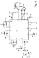
In der Fig. 4 ist eine Schaltung mit dem integrierten Schaltkreis 11 gezeigt, welche einen Miniaturempfänger bildet, der als Zusatz mit einem Hörgerät 38 sowohl mechanisch als auch elektrisch verbindbar ist. Die externen Bauelemente, die mit den Anschlusspunkten b, c, d, e, m, n, o, p, q und r verbunden sind, entsprechen dabei denjenigen, die bereits vorgängig anlässlich der Beschreibung der Figur 2 genannt worden sind und werden hier nicht ein zweites mal beschrieben. Der in diesem Beispiel gezeigte Empfänger wird, wenn er an das Hörgerät 38, in diesem Fall ein hinter dem Ohr zu tragendes Hörgerät, angekoppelt ist, über elektrisch erstellte Verbindungen von der im Hörgerät angeordneten Batterie B1 gespiesen. Die Batterie ist an die bereits vorgängig beschriebenen Anschlusspunkte e und f, über die die Siebkapazität C7 liegt, dauernd angeschaltet. Eine Verbindungsleitung zwischen dem Hörgerät und dem Anschlusspunkt g tastet, wie bereits gesagt, die gesiebte Mikrophonspeisespannung des Hörgerätes ab und sorgt bei einer unterbrochenen Mikrophonspeisespannung für einen Standby-Betrieb des Empfängers. Der Hörer H1, der ebenfalls im Hörgerät 38 angeordnet ist, ist über eine Kopplungskapazität C6 und über einen Schalter S2, entweder mit dem Anschlusspunkt h oder mit dem Anschlusspunkt i der integrierten Schaltung 11 verbunden. Die beiden Anschlusspunkte, an die je ein Niederfrequenzausgang des vorher beschriebenen Niederfrequenzverstärkers geschaltet ist, unterscheiden sich durch eine unterschiedliche Ausgangsimpedanz des Verstärkers. Durch Umlegen des Schalters S2 in die eine oder in die andere Stellung wird dem Hörgeräteträger vorgegeben, dass der Ton, der vom Mikrophon der Hörhilfe herrührt, abgeschwächt ist gegenüber dem Ton, der vom Miniaturempfänger empfangen wird oder dass in der anderen Stellung sowohl der Ton, der vom Mikrophon herrührt, als auch der Ton des Empfängers in etwa gleicher Lautstärke empfangen werden.4 shows a circuit with the
Mit einem weiteren Schalter S1 kann von der vorgängig beschriebenen magnetisch wirkenden Antenne 31 auf eine elektrisch wirkende Antenne 32, beispielsweise eine Draht-, Stab- oder Spulenantenne umgeschaltet werden.With a further switch S1, the magnetically acting
Ein konstruktives Ausführungsbeispiel eines als Hörgerätezusatz konzipierten Empfängers ist aus der Fig. 5 ersichtlich. Mit 38 ist der untere Teil des Gehäuses eines Hinter-dem-Ohr-Hörgerätes, in welchem üblicherweise die Batterie B1 in einer Batterieschublade angeordnet ist, gezeigt. Der Hörgerätezusatz ist in einem separaten Gehäuse 35 untergebracht, welches mittels mechanischen Verbindungsmitteln 36 am Gehäuse 38 des Hörgerätes lösbar befestigbar ist. Die erforderlichen elektrischen Verbindungen zum Hörgerät werden über elektrische Verbindungsmittel 37 hergestellt, wovon in der Fig. 5 lediglich ein federnder Stift, der den Kontakt zum einen Pol der Batterie herstellt, sichtbar ist. Innerhalb des Gehäuses 35 des Empfängers ist die Leiterplatte 34 sichtbar, auf welcher lediglich der Quarz Q1, nicht aber der integrierte Schaltkreis und die übrigen, in der Fig. 4 dargestellten externen Bauelemente gezeichnet ist. An dem dem Hörgerätegehäuse 38 abgewandten Ende des Gehäuses 35 ist eine Oeffnung vorhanden, durch welche die elektrisch wirkende Antenne 32 mit einem Anschlussstift 40 in eine Antennenbuchse 39, welche ebenfalls auf der Leiterplatte 34 montiert ist, einführbar ist. Bei eingeführter elektrisch wirkender Antenne 32 wird die Wirkung der magnetischen Antenne 31 unterbunden.A constructive embodiment of a receiver designed as a hearing aid accessory can be seen from FIG. 5. The lower part of the housing of a behind-the-ear hearing device, in which the battery B1 is usually arranged in a battery drawer, is shown at 38. The hearing aid accessory is accommodated in a
Claims (14)
Priority Applications (5)
| Application Number | Priority Date | Filing Date | Title |
|---|---|---|---|
| DE59410418T DE59410418D1 (en) | 1994-03-07 | 1994-03-07 | Miniature receiver for receiving a high frequency frequency or phase modulated signal |
| EP94810143A EP0671818B1 (en) | 1994-03-07 | 1994-03-07 | Miniature receiver for reception of frequency or phase modulated RF signals |
| DK94810143T DK0671818T3 (en) | 1994-03-07 | 1994-03-07 | Miniature receiver for receiving a high frequency frequency or phase modulated signal |
| AT94810143T ATE311694T1 (en) | 1994-03-07 | 1994-03-07 | MINIATURE RECEIVER FOR RECEIVING A HIGH FREQUENCY FREQUENCY OR PHASE MODULATED SIGNAL |
| US08/399,586 US5734976A (en) | 1994-03-07 | 1995-03-07 | Micro-receiver for receiving a high frequency frequency-modulated or phase-modulated signal |
Applications Claiming Priority (1)
| Application Number | Priority Date | Filing Date | Title |
|---|---|---|---|
| EP94810143A EP0671818B1 (en) | 1994-03-07 | 1994-03-07 | Miniature receiver for reception of frequency or phase modulated RF signals |
Publications (2)
| Publication Number | Publication Date |
|---|---|
| EP0671818A1 true EP0671818A1 (en) | 1995-09-13 |
| EP0671818B1 EP0671818B1 (en) | 2005-11-30 |
Family
ID=8218221
Family Applications (1)
| Application Number | Title | Priority Date | Filing Date |
|---|---|---|---|
| EP94810143A Expired - Lifetime EP0671818B1 (en) | 1994-03-07 | 1994-03-07 | Miniature receiver for reception of frequency or phase modulated RF signals |
Country Status (5)
| Country | Link |
|---|---|
| US (1) | US5734976A (en) |
| EP (1) | EP0671818B1 (en) |
| AT (1) | ATE311694T1 (en) |
| DE (1) | DE59410418D1 (en) |
| DK (1) | DK0671818T3 (en) |
Cited By (5)
| Publication number | Priority date | Publication date | Assignee | Title |
|---|---|---|---|---|
| WO1998037639A1 (en) | 1997-02-20 | 1998-08-27 | Telefonaktiebolaget Lm Ericsson (Publ) | Radio transceiver on a chip |
| CH691944A5 (en) * | 1997-10-07 | 2001-11-30 | Phonak Comm Ag | Hearing aid with external FM transmitter includes receiver mounted behind ear, and amplifier and speaker accommodated within ear |
| US6537200B2 (en) | 2000-03-28 | 2003-03-25 | Cochlear Limited | Partially or fully implantable hearing system |
| DE10361954A1 (en) * | 2003-12-23 | 2005-07-21 | Oliver Klammt | Hearing system and method for establishing such, and corresponding computer programs and corresponding computer-readable storage media |
| DE102009012753A1 (en) * | 2009-03-12 | 2010-09-16 | Rohde & Schwarz Gmbh & Co. Kg | Compensation of the degree of modulation dependence of a squelch for digital radio frequency receivers |
Families Citing this family (62)
| Publication number | Priority date | Publication date | Assignee | Title |
|---|---|---|---|---|
| US6978159B2 (en) | 1996-06-19 | 2005-12-20 | Board Of Trustees Of The University Of Illinois | Binaural signal processing using multiple acoustic sensors and digital filtering |
| US6987856B1 (en) | 1996-06-19 | 2006-01-17 | Board Of Trustees Of The University Of Illinois | Binaural signal processing techniques |
| US5937341A (en) * | 1996-09-13 | 1999-08-10 | University Of Washington | Simplified high frequency tuner and tuning method |
| US6249541B1 (en) * | 1996-11-29 | 2001-06-19 | Mitsubishi Denki Kabushiki Kaisha | Apparatus for removing shared waves |
| US6684063B2 (en) * | 1997-05-02 | 2004-01-27 | Siemens Information & Communication Networks, Inc. | Intergrated hearing aid for telecommunications devices |
| US6167246A (en) * | 1997-05-09 | 2000-12-26 | Micrel Incorporated | Fully integrated all-CMOS AM receiver |
| FR2787636B1 (en) | 1998-12-17 | 2001-03-16 | St Microelectronics Sa | SEMICONDUCTOR DEVICE WITH NOISE DECOUPLING BICMOS TYPE SUBSTRATE |
| EP1204980A4 (en) * | 1999-07-12 | 2006-01-18 | Energy Storage Systems Pty Ltd | An energy storage device |
| AU2001261344A1 (en) | 2000-05-10 | 2001-11-20 | The Board Of Trustees Of The University Of Illinois | Interference suppression techniques |
| US6313712B1 (en) | 2000-06-13 | 2001-11-06 | International Business Machines Corporation | Low power crystal oscillator having improved long term and short term stability |
| AU2000269773B2 (en) * | 2000-09-18 | 2006-03-02 | Phonak Ag | Method for controlling a transmission system, use of this method, transmission system, receiving unit and hearing aid |
| US7596237B1 (en) * | 2000-09-18 | 2009-09-29 | Phonak Ag | Method for controlling a transmission system, application of the method, a transmission system, a receiver and a hearing aid |
| US6794989B2 (en) * | 2001-06-25 | 2004-09-21 | Kara Jean Naegely | Sports signalling device for hearing impaired persons |
| JP2003018030A (en) * | 2001-06-29 | 2003-01-17 | Niigata Seimitsu Kk | Receiver |
| GB2379121A (en) * | 2001-08-07 | 2003-02-26 | James Edward Aman | Hands-free kit with inductive link |
| US6591786B1 (en) | 2002-02-13 | 2003-07-15 | Eric R. Davis | Device and method for safely inserting an electronic device in an ear of a four-legged non-human trained animal |
| US7369671B2 (en) | 2002-09-16 | 2008-05-06 | Starkey, Laboratories, Inc. | Switching structures for hearing aid |
| US7512448B2 (en) | 2003-01-10 | 2009-03-31 | Phonak Ag | Electrode placement for wireless intrabody communication between components of a hearing system |
| US7945064B2 (en) * | 2003-04-09 | 2011-05-17 | Board Of Trustees Of The University Of Illinois | Intrabody communication with ultrasound |
| US7076072B2 (en) * | 2003-04-09 | 2006-07-11 | Board Of Trustees For The University Of Illinois | Systems and methods for interference-suppression with directional sensing patterns |
| DK1627552T3 (en) * | 2003-05-09 | 2008-03-17 | Widex As | Hearing aid system, a hearing aid and a method for processing audio signals |
| US20050026587A1 (en) * | 2003-07-29 | 2005-02-03 | Miskho Michael S. | Radio frequency communication between devices via a power plane on a circuit board |
| DK1719384T3 (en) | 2004-02-19 | 2011-07-11 | Oticon As | Hearing aid with antenna for receiving and transmitting electromagnetic signals and shielding battery |
| US7272375B2 (en) | 2004-06-30 | 2007-09-18 | Silicon Laboratories Inc. | Integrated low-IF terrestrial audio broadcast receiver and associated method |
| US20060020454A1 (en) * | 2004-07-21 | 2006-01-26 | Phonak Ag | Method and system for noise suppression in inductive receivers |
| EP1619926A1 (en) * | 2004-07-21 | 2006-01-25 | Phonak Ag | Method and system for noise suppression in inductive receivers |
| US7593538B2 (en) | 2005-03-28 | 2009-09-22 | Starkey Laboratories, Inc. | Antennas for hearing aids |
| US9774961B2 (en) | 2005-06-05 | 2017-09-26 | Starkey Laboratories, Inc. | Hearing assistance device ear-to-ear communication using an intermediate device |
| US8041066B2 (en) | 2007-01-03 | 2011-10-18 | Starkey Laboratories, Inc. | Wireless system for hearing communication devices providing wireless stereo reception modes |
| EP1922899A1 (en) * | 2005-07-26 | 2008-05-21 | Abolghasem Chizari | Digital wireless information delivery system |
| DE102005046169A1 (en) | 2005-09-27 | 2007-04-05 | Siemens Audiologische Technik Gmbh | Hearing aid with an antenna |
| DE602006009063D1 (en) | 2006-02-13 | 2009-10-22 | Phonak Comm Ag | Method and system for providing hearing aid to a user |
| EP1821571A1 (en) * | 2006-02-15 | 2007-08-22 | Oticon A/S | Loop antenna for in the ear audio device |
| EP1843467B1 (en) * | 2006-04-07 | 2010-05-26 | Rohde & Schwarz GmbH & Co. KG | Method and apparatus for squelch gating a receiving signal |
| US20070258613A1 (en) * | 2006-05-03 | 2007-11-08 | Wright Kenneth A | Wearable personal sound delivery apparatus |
| US20070282392A1 (en) * | 2006-05-30 | 2007-12-06 | Phonak Ag | Method and system for providing hearing assistance to a user |
| US7738666B2 (en) * | 2006-06-01 | 2010-06-15 | Phonak Ag | Method for adjusting a system for providing hearing assistance to a user |
| US8208642B2 (en) | 2006-07-10 | 2012-06-26 | Starkey Laboratories, Inc. | Method and apparatus for a binaural hearing assistance system using monaural audio signals |
| US7940945B2 (en) * | 2006-07-06 | 2011-05-10 | Phonak Ag | Method for operating a wireless audio signal receiver unit and system for providing hearing assistance to a user |
| US20080102906A1 (en) * | 2006-10-30 | 2008-05-01 | Phonak Ag | Communication system and method of operating the same |
| US8934984B2 (en) * | 2007-05-31 | 2015-01-13 | Cochlear Limited | Behind-the-ear (BTE) prosthetic device with antenna |
| WO2009089136A1 (en) * | 2008-01-07 | 2009-07-16 | Etymotic Research, Inc. | Two-way communication device with detachable boom |
| US8737658B2 (en) | 2008-12-19 | 2014-05-27 | Starkey Laboratories, Inc. | Three dimensional substrate for hearing assistance devices |
| US10142747B2 (en) | 2008-12-19 | 2018-11-27 | Starkey Laboratories, Inc. | Three dimensional substrate for hearing assistance devices |
| US8565457B2 (en) | 2008-12-19 | 2013-10-22 | Starkey Laboratories, Inc. | Antennas for standard fit hearing assistance devices |
| US8699733B2 (en) | 2008-12-19 | 2014-04-15 | Starkey Laboratories, Inc. | Parallel antennas for standard fit hearing assistance devices |
| US8494197B2 (en) | 2008-12-19 | 2013-07-23 | Starkey Laboratories, Inc. | Antennas for custom fit hearing assistance devices |
| GB0912774D0 (en) | 2009-07-22 | 2009-08-26 | Sensorcom Ltd | Communications system |
| US9986347B2 (en) * | 2009-09-29 | 2018-05-29 | Starkey Laboratories, Inc. | Radio frequency MEMS devices for improved wireless performance for hearing assistance devices |
| US9420385B2 (en) | 2009-12-21 | 2016-08-16 | Starkey Laboratories, Inc. | Low power intermittent messaging for hearing assistance devices |
| US8737653B2 (en) | 2009-12-30 | 2014-05-27 | Starkey Laboratories, Inc. | Noise reduction system for hearing assistance devices |
| WO2011159349A1 (en) | 2010-06-14 | 2011-12-22 | Audiotoniq, Inc. | Hearing aid system |
| US9167339B2 (en) | 2010-07-07 | 2015-10-20 | Iii Holdings 4, Llc | Hearing damage limiting headphones |
| US8515110B2 (en) | 2010-09-30 | 2013-08-20 | Audiotoniq, Inc. | Hearing aid with automatic mode change capabilities |
| US8712083B2 (en) | 2010-10-11 | 2014-04-29 | Starkey Laboratories, Inc. | Method and apparatus for monitoring wireless communication in hearing assistance systems |
| US10687150B2 (en) * | 2010-11-23 | 2020-06-16 | Audiotoniq, Inc. | Battery life monitor system and method |
| US20120189140A1 (en) * | 2011-01-21 | 2012-07-26 | Apple Inc. | Audio-sharing network |
| US8929559B2 (en) * | 2011-03-01 | 2015-01-06 | Starkey Laboratories, Inc. | Method and apparatus for selecting right and left circuit configurations of hearing assistance devices |
| US9191756B2 (en) | 2012-01-06 | 2015-11-17 | Iii Holdings 4, Llc | System and method for locating a hearing aid |
| US10003379B2 (en) | 2014-05-06 | 2018-06-19 | Starkey Laboratories, Inc. | Wireless communication with probing bandwidth |
| EP3257265B1 (en) | 2015-02-09 | 2020-03-11 | Starkey Laboratories, Inc. | Ear-to-ear communication using an intermediate device |
| US10084625B2 (en) | 2017-02-18 | 2018-09-25 | Orest Fedan | Miniature wireless communication system |
Citations (2)
| Publication number | Priority date | Publication date | Assignee | Title |
|---|---|---|---|---|
| DE3032311A1 (en) * | 1979-08-30 | 1981-03-26 | Phonak AG für Elektro-Akustik, Feldmeilen | HOERING DEVICE WITH RECEIVER |
| DE3826294A1 (en) * | 1988-08-03 | 1990-02-08 | Bosch Gmbh Robert | Hands-free device for communications systems |
Family Cites Families (9)
| Publication number | Priority date | Publication date | Assignee | Title |
|---|---|---|---|---|
| US3979679A (en) * | 1975-06-30 | 1976-09-07 | California Microwave, Inc. | FM demodulator having squelch circuit using bucket brigade delay line |
| US4207590A (en) * | 1979-03-14 | 1980-06-10 | Rca Corporation | Combined phase shift filter network in a color video signal processing system employing dynamic flesh tone control |
| US4332032A (en) * | 1979-05-24 | 1982-05-25 | Lockheed Corporation | Adaptive hybrid antenna system |
| US4761829A (en) * | 1985-11-27 | 1988-08-02 | Motorola Inc. | Adaptive signal strength and/or ambient noise driven audio shaping system |
| US4873527A (en) * | 1988-01-07 | 1989-10-10 | Motorola, Inc. | Antenna system for a wrist carried paging receiver |
| JP2546331B2 (en) * | 1988-04-26 | 1996-10-23 | ソニー株式会社 | FM / AM receiver |
| FR2669802B1 (en) * | 1990-11-23 | 1993-06-18 | Intrason France | ELECTRONIC DEVICE FORMING MINIATURE PROGRAMMABLE HEARING AID, PARTICULARLY OF THE INTRA-DUCT TYPE. |
| US5498885A (en) * | 1994-09-26 | 1996-03-12 | Northern Telecom Limited | Modulation circuit |
| US5519762A (en) * | 1994-12-21 | 1996-05-21 | At&T Corp. | Adaptive power cycling for a cordless telephone |
-
1994
- 1994-03-07 DK DK94810143T patent/DK0671818T3/en active
- 1994-03-07 DE DE59410418T patent/DE59410418D1/en not_active Expired - Lifetime
- 1994-03-07 AT AT94810143T patent/ATE311694T1/en not_active IP Right Cessation
- 1994-03-07 EP EP94810143A patent/EP0671818B1/en not_active Expired - Lifetime
-
1995
- 1995-03-07 US US08/399,586 patent/US5734976A/en not_active Expired - Fee Related
Patent Citations (2)
| Publication number | Priority date | Publication date | Assignee | Title |
|---|---|---|---|---|
| DE3032311A1 (en) * | 1979-08-30 | 1981-03-26 | Phonak AG für Elektro-Akustik, Feldmeilen | HOERING DEVICE WITH RECEIVER |
| DE3826294A1 (en) * | 1988-08-03 | 1990-02-08 | Bosch Gmbh Robert | Hands-free device for communications systems |
Non-Patent Citations (2)
| Title |
|---|
| SONG ET AL: "A CMOS Double Heterodyne FM Receiver", IEEE JOURNAL OF SOLID STATE CIRCUITS, vol. SC-21, no. 6, December 1986 (1986-12-01), NEW YORK,US, pages 916 - 923, XP000816887, DOI: doi:10.1109/JSSC.1986.1052630 * |
| VAN DOOREMOLEN ET AL: "A Complete FM Radio on a Chip", ELECTRONIC COMPONENTS & APPLICATIONS, vol. 5, no. 3, June 1983 (1983-06-01), EINDHOVEN,NL, pages 159 - 170, XP000817014 * |
Cited By (9)
| Publication number | Priority date | Publication date | Assignee | Title |
|---|---|---|---|---|
| WO1998037639A1 (en) | 1997-02-20 | 1998-08-27 | Telefonaktiebolaget Lm Ericsson (Publ) | Radio transceiver on a chip |
| EP1524776A2 (en) | 1997-02-20 | 2005-04-20 | Telefonaktiebolaget LM Ericsson (publ) | Radio transceiver on a chip |
| EP1524776A3 (en) * | 1997-02-20 | 2005-09-21 | Telefonaktiebolaget LM Ericsson (publ) | Radio transceiver on a chip |
| EP1524777A3 (en) * | 1997-02-20 | 2005-09-21 | Telefonaktiebolaget LM Ericsson (publ) | Radio transceiver on a chip |
| CH691944A5 (en) * | 1997-10-07 | 2001-11-30 | Phonak Comm Ag | Hearing aid with external FM transmitter includes receiver mounted behind ear, and amplifier and speaker accommodated within ear |
| US6537200B2 (en) | 2000-03-28 | 2003-03-25 | Cochlear Limited | Partially or fully implantable hearing system |
| DE10361954A1 (en) * | 2003-12-23 | 2005-07-21 | Oliver Klammt | Hearing system and method for establishing such, and corresponding computer programs and corresponding computer-readable storage media |
| DE10361954B4 (en) * | 2003-12-23 | 2007-08-30 | Oliver Klammt | Hearing system and method for setting such a method for the detection of characteristic sound spectra, and corresponding computer programs and corresponding computer-readable storage media |
| DE102009012753A1 (en) * | 2009-03-12 | 2010-09-16 | Rohde & Schwarz Gmbh & Co. Kg | Compensation of the degree of modulation dependence of a squelch for digital radio frequency receivers |
Also Published As
| Publication number | Publication date |
|---|---|
| DK0671818T3 (en) | 2006-04-03 |
| US5734976A (en) | 1998-03-31 |
| ATE311694T1 (en) | 2005-12-15 |
| DE59410418D1 (en) | 2006-01-05 |
| EP0671818B1 (en) | 2005-11-30 |
Similar Documents
| Publication | Publication Date | Title |
|---|---|---|
| EP0671818B1 (en) | Miniature receiver for reception of frequency or phase modulated RF signals | |
| DE69132959T2 (en) | HEARING AID SYSTEM | |
| DE602004008962T2 (en) | TRANSMISSION RECEIVAL SWITCHING IN WIRELESS HEARING AID | |
| DE3109049C2 (en) | ||
| DE3512999A1 (en) | DIFFERENTIAL HEARING AID WITH PROGRAMMABLE FREQUENCY GEAR | |
| DE102013217545B4 (en) | SYSTEM AND METHOD FOR SENDING A HIGH FREQUENCY SIGNAL BY A SPEAKER COIL | |
| DE69122923T2 (en) | Stereo FM radio receiver in a television receiver | |
| DE1933150A1 (en) | Antenna for miniaturized radio equipment | |
| DE112013001294T5 (en) | Transducer with motion control | |
| DE3406899A1 (en) | MICROPHONE | |
| DE69016466T2 (en) | FM receiver and transmission system containing it. | |
| EP0089078B1 (en) | Circuit arrangement for an fm receiver | |
| EP1503612A2 (en) | Hearing aid and method for operating a hearing aid with a microphone system in which different directional characteristics are selectable | |
| DE60130006T2 (en) | HEARING DEVICE WITH A HIGH FREQUENCY RECEIVER | |
| DE69124311T2 (en) | Mono FM radio receiver in a television receiver | |
| EP0485357B1 (en) | Hearing aid with filter circuit | |
| DE69122332T2 (en) | Broadcast information reception in a television receiver by synthesis of the central frequency alone | |
| EP0821483B1 (en) | SC-filter with intrinsic anti-aliasing function and audio signal processor provided with the same | |
| DE69522568T2 (en) | hearing aid | |
| DE2931604C2 (en) | Noise-compensated microphone circuit | |
| EP0821479B1 (en) | Filter circuit and audio signal processor comprising the same | |
| AT403978B (en) | SINGLE CHANNEL CIRCUIT FOR A HEARING AID | |
| CH689887A5 (en) | Apparatus for hearing assistance. | |
| DE4125379C1 (en) | Hearing aid device with amplitude limitation - has limiting circuit inserted in feedback path for amplifier stage for matching frequency characteristic to each individual user | |
| DE69022702T2 (en) | Acoustic device. |
Legal Events
| Date | Code | Title | Description |
|---|---|---|---|
| PUAI | Public reference made under article 153(3) epc to a published international application that has entered the european phase |
Free format text: ORIGINAL CODE: 0009012 |
|
| AK | Designated contracting states |
Kind code of ref document: A1 Designated state(s): AT BE CH DE DK ES FR GB IT LI NL |
|
| 17P | Request for examination filed |
Effective date: 19951016 |
|
| 17Q | First examination report despatched |
Effective date: 20020305 |
|
| GRAP | Despatch of communication of intention to grant a patent |
Free format text: ORIGINAL CODE: EPIDOSNIGR1 |
|
| GRAS | Grant fee paid |
Free format text: ORIGINAL CODE: EPIDOSNIGR3 |
|
| GRAA | (expected) grant |
Free format text: ORIGINAL CODE: 0009210 |
|
| AK | Designated contracting states |
Kind code of ref document: B1 Designated state(s): AT BE CH DE DK ES FR GB IT LI NL |
|
| PG25 | Lapsed in a contracting state [announced via postgrant information from national office to epo] |
Ref country code: NL Free format text: LAPSE BECAUSE OF FAILURE TO SUBMIT A TRANSLATION OF THE DESCRIPTION OR TO PAY THE FEE WITHIN THE PRESCRIBED TIME-LIMIT Effective date: 20051130 Ref country code: IT Free format text: LAPSE BECAUSE OF FAILURE TO SUBMIT A TRANSLATION OF THE DESCRIPTION OR TO PAY THE FEE WITHIN THE PRE;WARNING: LAPSES OF ITALIAN PATENTS WITH EFFECTIVE DATE BEFORE 2007 MAY HAVE OCCURRED AT ANY TIME BEFORE 2007. THE CORRECT EFFECTIVE DATE MAY BE DIFFERENT FROM THE ONE RECORDED.SCRIBED TIME-LIMIT Effective date: 20051130 Ref country code: GB Free format text: LAPSE BECAUSE OF FAILURE TO SUBMIT A TRANSLATION OF THE DESCRIPTION OR TO PAY THE FEE WITHIN THE PRESCRIBED TIME-LIMIT Effective date: 20051130 |
|
| REG | Reference to a national code |
Ref country code: CH Ref legal event code: NV Representative=s name: BOVARD AG PATENTANWAELTE Ref country code: GB Ref legal event code: FG4D Free format text: NOT ENGLISH Ref country code: CH Ref legal event code: EP |
|
| REF | Corresponds to: |
Ref document number: 59410418 Country of ref document: DE Date of ref document: 20060105 Kind code of ref document: P |
|
| PG25 | Lapsed in a contracting state [announced via postgrant information from national office to epo] |
Ref country code: AT Free format text: LAPSE BECAUSE OF NON-PAYMENT OF DUE FEES Effective date: 20060307 |
|
| PG25 | Lapsed in a contracting state [announced via postgrant information from national office to epo] |
Ref country code: ES Free format text: LAPSE BECAUSE OF FAILURE TO SUBMIT A TRANSLATION OF THE DESCRIPTION OR TO PAY THE FEE WITHIN THE PRESCRIBED TIME-LIMIT Effective date: 20060313 |
|
| PG25 | Lapsed in a contracting state [announced via postgrant information from national office to epo] |
Ref country code: BE Free format text: LAPSE BECAUSE OF NON-PAYMENT OF DUE FEES Effective date: 20060331 |
|
| REG | Reference to a national code |
Ref country code: DK Ref legal event code: T3 |
|
| NLV1 | Nl: lapsed or annulled due to failure to fulfill the requirements of art. 29p and 29m of the patents act | ||
| GBV | Gb: ep patent (uk) treated as always having been void in accordance with gb section 77(7)/1977 [no translation filed] |
Effective date: 20051130 |
|
| PLBE | No opposition filed within time limit |
Free format text: ORIGINAL CODE: 0009261 |
|
| STAA | Information on the status of an ep patent application or granted ep patent |
Free format text: STATUS: NO OPPOSITION FILED WITHIN TIME LIMIT |
|
| 26N | No opposition filed |
Effective date: 20060831 |
|
| EN | Fr: translation not filed | ||
| BERE | Be: lapsed |
Owner name: PHONAK COMMUNICATIONS A.G. Effective date: 20060331 |
|
| PG25 | Lapsed in a contracting state [announced via postgrant information from national office to epo] |
Ref country code: FR Free format text: LAPSE BECAUSE OF FAILURE TO SUBMIT A TRANSLATION OF THE DESCRIPTION OR TO PAY THE FEE WITHIN THE PRESCRIBED TIME-LIMIT Effective date: 20070119 |
|
| PG25 | Lapsed in a contracting state [announced via postgrant information from national office to epo] |
Ref country code: FR Free format text: LAPSE BECAUSE OF FAILURE TO SUBMIT A TRANSLATION OF THE DESCRIPTION OR TO PAY THE FEE WITHIN THE PRESCRIBED TIME-LIMIT Effective date: 20060331 |
|
| PG25 | Lapsed in a contracting state [announced via postgrant information from national office to epo] |
Ref country code: FR Free format text: LAPSE BECAUSE OF FAILURE TO SUBMIT A TRANSLATION OF THE DESCRIPTION OR TO PAY THE FEE WITHIN THE PRESCRIBED TIME-LIMIT Effective date: 20051130 |
|
| PGFP | Annual fee paid to national office [announced via postgrant information from national office to epo] |
Ref country code: DK Payment date: 20100610 Year of fee payment: 17 |
|
| PGFP | Annual fee paid to national office [announced via postgrant information from national office to epo] |
Ref country code: DE Payment date: 20100525 Year of fee payment: 17 |
|
| PGFP | Annual fee paid to national office [announced via postgrant information from national office to epo] |
Ref country code: CH Payment date: 20100531 Year of fee payment: 17 |
|
| REG | Reference to a national code |
Ref country code: CH Ref legal event code: PFA Owner name: PHONAK COMMUNICATIONS AG Free format text: PHONAK COMMUNICATIONS AG#LAENGGASSE 17#1796 COURGEVAUX (CH) -TRANSFER TO- PHONAK COMMUNICATIONS AG#LAENGGASSE 17#1796 COURGEVAUX (CH) |
|
| REG | Reference to a national code |
Ref country code: CH Ref legal event code: PL Ref country code: DK Ref legal event code: EBP |
|
| PG25 | Lapsed in a contracting state [announced via postgrant information from national office to epo] |
Ref country code: DE Free format text: LAPSE BECAUSE OF NON-PAYMENT OF DUE FEES Effective date: 20111001 Ref country code: CH Free format text: LAPSE BECAUSE OF NON-PAYMENT OF DUE FEES Effective date: 20110331 Ref country code: LI Free format text: LAPSE BECAUSE OF NON-PAYMENT OF DUE FEES Effective date: 20110331 |
|
| REG | Reference to a national code |
Ref country code: DE Ref legal event code: R119 Ref document number: 59410418 Country of ref document: DE Effective date: 20111001 |
|
| PG25 | Lapsed in a contracting state [announced via postgrant information from national office to epo] |
Ref country code: DK Free format text: LAPSE BECAUSE OF NON-PAYMENT OF DUE FEES Effective date: 20110331 |