EP0671053B1 - An electric switch - Google Patents
An electric switch Download PDFInfo
- Publication number
- EP0671053B1 EP0671053B1 EP94900777A EP94900777A EP0671053B1 EP 0671053 B1 EP0671053 B1 EP 0671053B1 EP 94900777 A EP94900777 A EP 94900777A EP 94900777 A EP94900777 A EP 94900777A EP 0671053 B1 EP0671053 B1 EP 0671053B1
- Authority
- EP
- European Patent Office
- Prior art keywords
- rotatable member
- lever
- electric
- electric switch
- switch
- Prior art date
- Legal status (The legal status is an assumption and is not a legal conclusion. Google has not performed a legal analysis and makes no representation as to the accuracy of the status listed.)
- Expired - Lifetime
Links
- 230000008878 coupling Effects 0.000 claims abstract description 16
- 238000010168 coupling process Methods 0.000 claims abstract description 16
- 238000005859 coupling reaction Methods 0.000 claims abstract description 16
- 239000004020 conductor Substances 0.000 claims description 5
- 238000010586 diagram Methods 0.000 description 9
- 238000010276 construction Methods 0.000 description 3
- 229910052751 metal Inorganic materials 0.000 description 2
- 230000000717 retained effect Effects 0.000 description 2
- 230000004913 activation Effects 0.000 description 1
- 230000001419 dependent effect Effects 0.000 description 1
- 230000014759 maintenance of location Effects 0.000 description 1
- 238000000034 method Methods 0.000 description 1
- 230000000284 resting effect Effects 0.000 description 1
Images


Classifications
-
- A—HUMAN NECESSITIES
- A63—SPORTS; GAMES; AMUSEMENTS
- A63H—TOYS, e.g. TOPS, DOLLS, HOOPS OR BUILDING BLOCKS
- A63H33/00—Other toys
- A63H33/04—Building blocks, strips, or similar building parts
- A63H33/042—Mechanical, electrical, optical, pneumatic or hydraulic arrangements; Motors
-
- H—ELECTRICITY
- H01—ELECTRIC ELEMENTS
- H01H—ELECTRIC SWITCHES; RELAYS; SELECTORS; EMERGENCY PROTECTIVE DEVICES
- H01H11/00—Apparatus or processes specially adapted for the manufacture of electric switches
- H01H11/0006—Apparatus or processes specially adapted for the manufacture of electric switches for converting electric switches
- H01H11/0018—Apparatus or processes specially adapted for the manufacture of electric switches for converting electric switches for allowing different operating parts
-
- H—ELECTRICITY
- H01—ELECTRIC ELEMENTS
- H01H—ELECTRIC SWITCHES; RELAYS; SELECTORS; EMERGENCY PROTECTIVE DEVICES
- H01H19/00—Switches operated by an operating part which is rotatable about a longitudinal axis thereof and which is acted upon directly by a solid body external to the switch, e.g. by a hand
- H01H19/54—Switches operated by an operating part which is rotatable about a longitudinal axis thereof and which is acted upon directly by a solid body external to the switch, e.g. by a hand the operating part having at least five or an unspecified number of operative positions
- H01H19/56—Angularly-movable actuating part carrying contacts, e.g. drum switch
-
- H—ELECTRICITY
- H01—ELECTRIC ELEMENTS
- H01H—ELECTRIC SWITCHES; RELAYS; SELECTORS; EMERGENCY PROTECTIVE DEVICES
- H01H2223/00—Casings
- H01H2223/03—Separate key housing
- H01H2223/032—Separate key housing with formations for assembling similar housings
-
- H—ELECTRICITY
- H01—ELECTRIC ELEMENTS
- H01H—ELECTRIC SWITCHES; RELAYS; SELECTORS; EMERGENCY PROTECTIVE DEVICES
- H01H3/00—Mechanisms for operating contacts
- H01H3/02—Operating parts, i.e. for operating driving mechanism by a mechanical force external to the switch
- H01H3/16—Operating parts, i.e. for operating driving mechanism by a mechanical force external to the switch adapted for actuation at a limit or other predetermined position in the path of a body, the relative movement of switch and body being primarily for a purpose other than the actuation of the switch, e.g. for a door switch, a limit switch, a floor-levelling switch of a lift
- H01H3/161—Operating parts, i.e. for operating driving mechanism by a mechanical force external to the switch adapted for actuation at a limit or other predetermined position in the path of a body, the relative movement of switch and body being primarily for a purpose other than the actuation of the switch, e.g. for a door switch, a limit switch, a floor-levelling switch of a lift for actuation by moving a closing member, e.g. door, cover or lid
- H01H3/162—Operating parts, i.e. for operating driving mechanism by a mechanical force external to the switch adapted for actuation at a limit or other predetermined position in the path of a body, the relative movement of switch and body being primarily for a purpose other than the actuation of the switch, e.g. for a door switch, a limit switch, a floor-levelling switch of a lift for actuation by moving a closing member, e.g. door, cover or lid associated with a hinge of the closing member
Definitions
- the invention concerns an electric switch for toys and comprising a stationary member and a member rotatable with respect to the stationary member, said stationary member having a plurality of electric connections which are broken and made by rotation of the rotatable member.
- US patent specification 3 480 752 discloses a contact or switch having a removable, protruding lever. A coupling is established between this lever and the rotatable shaft of the contact, permitting the lever to be assembled and removed without the switch being loaded critically. The shown switch can be moved between two extreme positions, and it is not explained how the electric connections of the contact are actually made.
- US patent specification 4 313 041 discloses a switch for mounting on a printed circuit board. Here it is often of interest to break and make several circuits at the same time. Such printed circuit boards are often encased in a housing or a box and are therefore not very accessible. With the technique described in the patent specification several switches can be coupled together axially by means of a through shaft. When a switch is operated, the shaft coupling brings along the other switches incorporated in the coupling. The contact is established by means of a rocking body in the form of a rocker spring by means of which a contact point can be connected with two alternative contact points.
- US patent 4 313 041 discloses a switch according to the preamble of claim 1. Such a switch is only capable of performing simple on/off operations or switchings but no sequences of opening and closing the switch elements.
- the object of the invention is to provide an electric switch for use in connection with toys, which can be employed for performing a plurality of switching functions, e.g. as an on/off element, a pole reverser or a sequence device, depending upon the coupling.
- a plurality of switching functions e.g. as an on/off element, a pole reverser or a sequence device, depending upon the coupling.
- an electric switch here constructed as stated in the characterizing portion of claim 1.
- the electric connections of the stationary member can be actuated by moving the lever from one position to another, causing the rotatable member to be rotated.
- the protruding lever is removed from the rotatable member, this can be driven by an external drive, so that the contacts are actuated periodically by the rotation of the rotatable member.
- the electric connections are hereby broken and made sequentially.
- the pattern of the made contacts runs through a sequence by rotation of the rotatable member, and this sequence may be divided into a plurality of subsequences which are symmetrical, i.e.
- the make pattern is the same in clockwise as well as counterclockwise rotation, it being possible to arrange the coupling means on the rotatable member such that the protruding lever can be mounted in a number of positions corresponding to the number of subsequences multiplied by two. Then, when the lever is in its one extreme position in the slot, it will hereby be possible to remove the lever and to mount it in the coupling means at the other end of the slot. Exactly the same sequence portion will hereby be run through when the arm is moved in the slot, as when the arm was in the first position; but the run-through will be directed opposite to the run-through of the first position. When the switch is used in an on/off function, it will thus be possible to reverse the on/off positions merely be moving the lever.
- the terminal parts on the electric connections of the stationary member may advantageously be constructed as stated in claim 3, the terminal parts being constructed as leaf springs which overlap each other over part of their longitudinal direction.
- the two terminal parts When one of the leaf springs of a terminal part deflects, the two terminal parts will be contacted with each other, and this can take place in that radially protruding bosses are provided on the rotating member which, upon rotation of the rotatable member, bring the leaf springs into contact with each other when the bosses pass them.
- the length of the bosses in the circumference of the rotatable member may be varied from just a few degrees to a considerable portion of the circumference of the rotatable member, thereby also changing the part of the period of the rotatable member in which the connection is made.
- the terminal parts may be constructed as stated in claim 4, since the conducting material on one of the paths may be used for making several electric connections.
- the collector shoes are expediently provided on a leaf spring, so that the collector shoes engage a rotating member and press against the path with a force well-defined in advance.
- the switch of claim 5 is unique in that precisely two identical subsequences are run through by rotation of the rotatable member, it being possible to mount the protruding lever in four positions.
- This switch is particularly useful as a pole reverser, which is stated in claim 10.
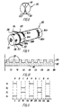
- Fig. 1 shows a switch according to the invention, which is generally designated by the reference numeral 10.
- the switch 10 has a rotating member 16 which is mounted between the lower part 12 and the upper part 13 of a stationary member.
- the upper part 13 of the stationary member is formed with coupling studs 14 on its upper side for connection with the other building elements of a construction building set, said coupling studs 14 being formed with conductive contact faces 15 along part of their side faces.
- the rotating member 16 has an axial passage 20, which preferably extends therethrough, and in which a shaft member 11 is to be received and retained by friction.
- the through passage 20 is here formed with a cruciform cross-section, so that it has a cross-section which corresponds to one of the existing elements of the construction building set.
- the coupling studs 14 on one side of the rotating member 16 serve as input terminals.
- the coupling studs on the other side of the rotating member 16 then serve as output terminals.
- the design of the coupling studs 14 and their electric and mechanical connection with other components of the toy building set are described in US patent specification 4 552 541.
- the preferred embodiment includes a first and a second input terminal 15a and 15b and a first and a second output terminal 15c and 15d.
- the stationary member includes a plurality of electric connections which are made and broken when the shaft 11 rotates.
- the electric connections between the terminal parts 15a-b and 15c-d of the input and output ends will be broken and made periodically.
- An arched portion 21 in the upper part 13 is shown with a slot 21 through which the rotating member 16 with a cruciform hole 18 is visible.
- Notches 17, whose function will be explained in connection with fig. 2 are provided along the rim of the slot 22.
- Fig. 2 shows the switch of fig. 1 in which the cruciform shaft 11 is replaced by a lever 19, which is received in the slot 22 on the arched portion 21, said lever 19 being introduced into the cruciform hole 18 on the rotating member 16. Reception and retention take place by friction, and when the lever 19 is moved in the directions shown by the arrow, it is possible to rotate the rotating member 16, so that, when replacing the shaft 11 with a radially protruding lover 19, the switch of fig. 1, which periodically runs through a make pattern, can be converted to a switch which makes it possible to select between a plurality of the make states.
- the notches 17 along the slot 22 serve as marked positions of the lever 19, which has a width such that the stationary member is subjected to small internal stresses when the lever 19 is not aligned with the notches 17, but is at rest when the lever 19 is aligned with a notch 17.
- a notch 17 corresponds to a switch position and thus to an intended connection between the input and output terminals of the switch.
- Fig. 3 is an exploded view of the switch of fig. 2, and it will be seen that the protruding lever 19 has a cruciform shaft part as well as a head in which a cruciform shaft can be received transversely.
- the upper part 13, which is substantially shaped as an ⁇ , will be explained more fully in connection with fig. 4.
- the rotatable member 16 is substantially cylindrical and has two ring-shaped faces 25 at its respective ends, said faces 25 resting on bearing faces 30 on the lower portion of the stationary part.
- the rotatable member has four sets of bosses 23, 24, each set consisting of two bosses located diametrically in pairs.
- the bosses 23, 24 are rounded in the circumferential direction of the rotatable member.
- the bosses 23 and 24 are arranged 90° offset with respect to each other, and their extent in the circumferential direction corresponds to an angle of about 45°.
- the actual contact between the input terminals 15a-b and the output terminals 15c-d of the switch is established by means of four conductive and resilient metal elements 26-29.
- Each of the elements 26-29 has a coupling part 26a-29a by means of which contact is established with the terminals 15a-d on the coupling studs 14 when the switch has been assembled.
- the elements 26-29 branch in a number of branches corresponding to the number of input/output terminals - here two. Two of the branches on the elements 28 and 29 intersect each other, so that the branches 26b-29b are caused to overlap each other in a manner such that the branches 26b on the element 26 overlap branches 28b and 29b on the elements 28 and 29, respectively.
- the branches 27b on the element 27 overlap a respective branch 28b and 29b on the elements 28 and 29. Since the mutual overlap of the branches 26b-29b creates an air gap between the overlapping portions, contact between the input terminals 15a-b and the output terminals 15a-d can be established by pressing selected branches 26b-27b against the branches 28b-29b.
- the lower part 12 of the stationary member has two upright wall portions 30 which serve as bearings for the rotating member 16.
- the lower part 12 interiorly has eight projections 31, by means of which the conducting elements 26-29 are fixed with respect to the upper part 13 of the stationary member.
- the lower part 12 has two lower projections 32 which cooperate with corresponding projections on the underside of the upper part 13 to retain the branches 26b-29b in a predetermined well-defined mutually spaced relation.
- Fig. 4 shows the upper part 13 of the stationary member, and it will be seen that the conducting metal elements 26-28 are arranged such that the branches 26b-29b overlap each other. Also the ring-shaped faces 25 on the rotatable member 16 are visible. It will be seen that flaps 35 protrude from the elements 26-29 substantially at right angles from said elements. The function of the flaps 35 is to retain the conducting elements 26-29 in their position, and the flaps thus serve the same purpose as the projections 31.
- each of the elements 26-29 is formed with a slot 36 in which a protruding flap in contact with the terminals 15a-15d ensures electric connection with the conducting elements 26-29. The flaps in the slot 36 are retained by friction.
- Fig. 5 shows the circuit diagram of the switch of figs. 1-4.
- Four nodes 126-129 are connected to respective electric terminals 15a-15d, and it will be seen that the diagram of the electric circuit contains four contacts K1-K4.
- the contacts K1-K4 are made in pairs, which means that K1 and K4 are made at the same time, and that K2 and K3 are made at the same time.
- K1 and K4 have been made, the node 128 is connected to the node 127, and the node 129 is connected to the node 126.
- K2 and K3 are made, the node 128 is connected to the node 126, while the node 129 is connected to the node 127.
- the chosen bosses enable the establishment of a make pattern having a number of states, which can e.g. correspond to a rotation of 45° each.
- the state A indicates that the node 127 is connected to the node 128, and that the node 126 is connected to the node 129.
- the state B indicates that there is no contact between the nodes 126, 127 and the nodes 128, 129.
- the state C indicates that the node 126 is connected to the node 128, and that the node 127 is connected to the node 129.
- rotation of the rotating member 16 results in run-through of a make sequence ABCBABCBA when the rotating member 16 is rotated a full revolution.
- this sequence is formed by two subsequences ABCBA, which is utilized with the embodiment shown in fig. 2, it being here possible e.g. to place the bushings 18 in the rotating member 16 (fig. 3) in positions which correspond to the angular positions 0°, 90°, 180°, 270° (fig. 11).
- state A may be established in one extreme position and state C in the other extreme position, while state B (where the output terminals are isolated from the input terminals) is obtained in the central position.
- state B where the output terminals are isolated from the input terminals
- Fig. 6 shows an alternative embodiment of an electric circuit diagram that can be achieved with a switch of the type shown in figs. 1-4.
- This embodiment includes three different input terminals 130-132 that can be connected to the output terminals 133-135. This is done by making the contacts in the same manner as explained in connection with fig. 5, the contacts K1, K4 and K7 being made at the same time, which also applies to the contacts K2, K5, and K8 and K3, K6, and K9, respectively.
- the node 133 is hereby successively brought into contact with the nodes 132, 131, 130, while the node 134 is similarly successively brought into contact with the nodes 131, 130 and 132, and the node 135 is successively brought into contact with the nodes 130, 132 and 131.
- the make pattern upon rotation of the rotating member 16 will be as follows ADBDCDADBD..., when D indicates the state where there is no contact between any of the terminals 130-132 and the terminals 133-135. It will be appreciated that the subsequences do not have the same symmetry as the one obtained in connection with fig. 11; but this is merely a question of adapting the position of the bosses on the rotating member such that the desired symmetry can be obtained.
- Fig. 7 shows a further electrical diagram of a switch according to the invention, in which four inputs 136-139 can be connected to respective outputs 140-143 when the contacts K1-K4 are made.
- the switch is extremely simple, since the electric connection between an input terminal and an output terminal is broken and made as a consequence of the rotation of a rotatable member.
- the nodes 140-143 are connected to the same source of voltage, the nodes 136-139 can represent a digital signal consisting of 4 bits.
- the actual value of the digital signal represented on the nodes 136-139 is dependent on the position of the contacts K1-K4.
- the bosses of the rotating member can be constructed such that the digital signal is counted up from zero to fifteen, and then down to zero again.
- Fig. 9 shows an alternative embodiment of a rotatable member for a switch according to the invention.
- the rotatable member is generally designated by the reference numeral 150, and it will be seen that it is substantially cylindrical and provided with an axial passage 151 to receive a shaft part and with a plurality of radially extending passages 156 in which radially extending levers can be mounted. It is noted that the passages 156 are provided at one end of the rotatable member. Both the shafts (not shown) and the extending levers can of course be received in manners known per se by friction or by snaplocking or the like.
- each path 160a-160N being formed with one or more path segments 161a-161N which are coated with conductive material.
- a plurality of collector shoes 152-155 of an electrically conductive material are pressed against and are in contact with each of the paths 160a-160N during the rotation of the rotatable member 150. There will thus be electric contact between two collector shoes when both of these are in contact with the same conductive segment 161a-161N.
- the number of collector shoes 152-155 in contact with the same path 160a-160N is at least two.
- Fig. 8 schematically shows a rotatable member 150 having two collector shoes 152, 153. These are arranged at a certain mutual distance, which, in terms of angle, corresponds to an angular distance ⁇ .
- Conductive material is provided along an angular segment 161 corresponding to an angle ⁇ of the entire circumference.
- the angle ⁇ lust be greater than the angle ⁇ .
- a path 160 (fig. 9) can be replaced by a path 180 which is shown in fig. 10.
- the path 180 is conductive along the entire circumference of the rotating body 140, and it has a plurality of protruding branches 181. The two collector shoes are then displaced mutually in the axial direction of the rotatable body, so that one collector shoe, e.g.
- the one to which an input voltage is applied sweeps over part of the path corresponding to the one marked in dashed lines 182.
- the other collector shoe which is connected to the output terminal in this case, is caused to sweep over the part of the path marked in dashed lines 183.
- voltage will be applied to the conducting path part 180, 181 all the time, while the collector show on the output side will be in contact with the conducting path only when it passes the protruding branches 181.
- a damper may be incorporated to dampen electric noise, as will be well-known to a skilled person.
- the rotating member is not necessarily shaped as a drum, but may assume other forms suitable for the purpose.
- the rotating member shown in fig. 2 may be disc-shaped, and the partly conductive paths may be arranged to extend around the circular end faces of the member.
- the member may also be pully-shaped with end flanges, with the actuation means located between the flanges.
- projections may be provided on- the end faces of the rotating member, and these projections, like the projections shown in figs. 1-4, break and make the electric connections of the stationary member.
Landscapes
- Engineering & Computer Science (AREA)
- Manufacturing & Machinery (AREA)
- Rotary Switch, Piano Key Switch, And Lever Switch (AREA)
Abstract
Description
Claims (5)
- An electric switch comprising a stationary member (12, 13) having a plurality of electric switch elements (26-29), and a rotatable member (16) mounted rotatably with respect to the stationary member, the rotatable member having actuation means (23, 161) which upon rotation of the rotatable member is capable of electrically opening and closing the electric switch elements (26-29), the rotatable member further having an axial opening (20) for receiving a drive shaft (11) for rotating the rotatable member (16), and coupling means (18) for detachably mounting a radially protruding lever (19) for rotating the rotatable member (16), a slot (22) being provided in the stationary member (12, 13) for receiving the lever (19) and restricting the mobility of the lever (19) when received in the slot (22), characterized in that upon rotation of the rotatable member (16) the opening and closing pattern of the electric switch elements (26-29) runs through a sequence consisting of a plurality of symmetrical subsequences (ABCBA), the opening and closing pattern being the same when rotating the rotatable member (16) in either direction, and that the rotatable member (16) has a number of angularly spaced mounting positions for the lever (19) corresponding to twice the number of subsequences per revolution, and that the extent of the slot is such that half a subsequence (ABC, CBA) is run through upon movement of the lever (19) between two extreme positions.
- A switch according to claim 1 characterized in that the coupling means (18) and the axial opening (20) have cruciform cross-sections.
- A switch according to claim 1-2 characterized in that the electric switch elements (26-29) have terminal parts (26b-29b; 152-155) in the form of overlapping, but spaced leaf springs, which upon rotation of the rotatable member (16) are pressed against each other by radially protruding bosses (23, 24) on the rotatable member (16) and thereby establishing electric connections between terminal parts (26b-29b; 152-155).
- A switch according to claim 1-2 characterized in that the electric switch elements (26-29) have collector shoes (151-155) which are in sliding contact with the rotatable member (150) along annular paths (160a-160n) thereon, and that electric connection is established in that the paths (160a-160n) on part (161a-161n) of their circumference are coated with conductive material which interconnects the terminal parts during rotation of the rotatable member (150).
- A switch according to claim 1-4 characterized in that the opening and closing pattern runs through a sequence consisting of two identical subsequences (ABCBA), and that the slot (22) extends along one quarter of the circumference of the rotatable member (16).
Applications Claiming Priority (4)
| Application Number | Priority Date | Filing Date | Title |
|---|---|---|---|
| DK921408A DK140892D0 (en) | 1992-11-24 | 1992-11-24 | ELECTRICAL SWITCHES |
| DK1408/92 | 1992-11-24 | ||
| DK140892 | 1992-11-24 | ||
| PCT/DK1993/000381 WO1994013001A1 (en) | 1992-11-24 | 1993-11-23 | An electric switch |
Publications (2)
| Publication Number | Publication Date |
|---|---|
| EP0671053A1 EP0671053A1 (en) | 1995-09-13 |
| EP0671053B1 true EP0671053B1 (en) | 1998-01-21 |
Family
ID=8104513
Family Applications (1)
| Application Number | Title | Priority Date | Filing Date |
|---|---|---|---|
| EP94900777A Expired - Lifetime EP0671053B1 (en) | 1992-11-24 | 1993-11-23 | An electric switch |
Country Status (7)
| Country | Link |
|---|---|
| US (1) | US5596181A (en) |
| EP (1) | EP0671053B1 (en) |
| JP (1) | JPH08505489A (en) |
| AU (1) | AU5560994A (en) |
| DE (1) | DE69316650T2 (en) |
| DK (1) | DK140892D0 (en) |
| WO (1) | WO1994013001A1 (en) |
Families Citing this family (23)
| Publication number | Priority date | Publication date | Assignee | Title |
|---|---|---|---|---|
| DE19703962C1 (en) * | 1997-02-03 | 1998-06-10 | Siemens Ag | Circuit breaker for switching electrical circuits |
| US5924905A (en) * | 1997-09-24 | 1999-07-20 | Parvia Corporation | Modular terrain for a toy building set |
| US5951356A (en) * | 1997-10-27 | 1999-09-14 | Parvia Corporation | Modular lattice substructure for a toy building set having columns and foundations |
| US6129605A (en) * | 1997-09-24 | 2000-10-10 | Parvia Corporation | Modular base units for a toy building set |
| US5947787A (en) * | 1997-09-24 | 1999-09-07 | Parvia Corporation | Modular lattice substructure for a toy building set |
| US5993283A (en) * | 1997-09-30 | 1999-11-30 | Parvia Corporation | Modular buildings for a toy building set |
| US6007401A (en) * | 1997-10-03 | 1999-12-28 | Parvia Corporation | Optoelectric remote control apparatus for guiding toy vehicles |
| US6102770A (en) * | 1997-10-03 | 2000-08-15 | Parvia Corporation | Toy vehicular electromechanical guidance apparatus |
| US5865661A (en) * | 1997-10-03 | 1999-02-02 | Parvia Corporation | Toy vehicular drive apparatus |
| US6012957A (en) * | 1997-10-27 | 2000-01-11 | Parvia Corporation | Single beam optoelectric remote control apparatus for control of toys |
| JP3428532B2 (en) * | 1999-10-22 | 2003-07-22 | 日本電気株式会社 | Opening / closing angle detecting device and folding device |
| US7197860B2 (en) * | 2003-11-17 | 2007-04-03 | Vacnseal Holdings, Llc | Method and apparatus for vacuum sealing |
| US7525533B2 (en) * | 2005-09-29 | 2009-04-28 | Sony Corporation | Audio communication device and audio communication method |
| US8015657B2 (en) * | 2007-02-09 | 2011-09-13 | Black & Decker Inc. | Vacuum electronic power tool sense |
| US7962994B2 (en) * | 2007-10-11 | 2011-06-21 | Black & Decker Inc. | Vacuum electronic switch detection system |
| US8516650B2 (en) * | 2007-10-11 | 2013-08-27 | Black & Decker Inc. | Vacuum electronic water sense circuit |
| US7644469B2 (en) * | 2007-10-11 | 2010-01-12 | Black & Decker Inc. | Vacuum electronics isolation method |
| US8690631B2 (en) * | 2008-09-12 | 2014-04-08 | Texas Instruments Incorporated | Toy building block with embedded integrated circuit |
| US8872053B2 (en) * | 2010-05-27 | 2014-10-28 | Apple Inc. | Sliding button with rotating shaft |
| US20130217294A1 (en) * | 2012-02-17 | 2013-08-22 | Arjuna Ragunath Karunaratne | Toy brick with sensing, actuation and control |
| WO2013122798A1 (en) | 2012-02-17 | 2013-08-22 | Technology One, Inc. | Baseplate assembly for use with toy pieces |
| CA3275029A1 (en) | 2014-05-15 | 2025-10-30 | Lego A/S | A toy construction system with function construction elements |
| FR3032303B1 (en) * | 2015-02-03 | 2018-04-27 | Legrand France | TRAINER FOR AN ELECTRIC SWITCH AND ELECTRIC SWITCH COMPRISING SUCH A TRAINER |
Family Cites Families (8)
| Publication number | Priority date | Publication date | Assignee | Title |
|---|---|---|---|---|
| US3480752A (en) * | 1968-07-26 | 1969-11-25 | Cherry Electrical Prod | Switch actuator |
| US3617676A (en) * | 1970-06-24 | 1971-11-02 | Arrow Hart Inc | Switch handle for field assembly |
| DE2225066A1 (en) * | 1971-06-22 | 1974-06-27 | Febana | MINIATURE STEP TURN SWITCH |
| FR2389988A1 (en) * | 1977-05-05 | 1978-12-01 | Neiman Sa | Lockable rotary switch with multiple contacts - has cylinder lock freeing rotating contact barrel |
| US4133990A (en) * | 1977-06-27 | 1979-01-09 | Globe-Union Inc. | Rotary switch |
| US4272658A (en) * | 1978-11-16 | 1981-06-09 | Beckman Instruments, Inc. | Multi-contact rotary switch |
| US4313041A (en) * | 1978-12-25 | 1982-01-26 | Shigeo Ohashi | Small switch |
| US4855541A (en) * | 1986-10-08 | 1989-08-08 | Omron Tateisi Electronics Co. | Electronic component having improved rotary switch detent spring construction and improved terminal seal structure |
-
1992
- 1992-11-24 DK DK921408A patent/DK140892D0/en not_active Application Discontinuation
-
1993
- 1993-11-23 US US08/433,418 patent/US5596181A/en not_active Expired - Fee Related
- 1993-11-23 EP EP94900777A patent/EP0671053B1/en not_active Expired - Lifetime
- 1993-11-23 JP JP6512664A patent/JPH08505489A/en active Pending
- 1993-11-23 WO PCT/DK1993/000381 patent/WO1994013001A1/en not_active Ceased
- 1993-11-23 DE DE69316650T patent/DE69316650T2/en not_active Expired - Fee Related
- 1993-11-23 AU AU55609/94A patent/AU5560994A/en not_active Abandoned
Also Published As
| Publication number | Publication date |
|---|---|
| AU5560994A (en) | 1994-06-22 |
| EP0671053A1 (en) | 1995-09-13 |
| JPH08505489A (en) | 1996-06-11 |
| DK140892D0 (en) | 1992-11-24 |
| US5596181A (en) | 1997-01-21 |
| DE69316650T2 (en) | 1998-06-18 |
| DE69316650D1 (en) | 1998-02-26 |
| WO1994013001A1 (en) | 1994-06-09 |
Similar Documents
| Publication | Publication Date | Title |
|---|---|---|
| US5596181A (en) | Electric switch | |
| US4133990A (en) | Rotary switch | |
| US4625084A (en) | Rotary switch construction and method of making the same | |
| US4728755A (en) | Rotary switch construction and method of making the same | |
| US6087607A (en) | Position signalling device | |
| US3734869A (en) | Rotary switch assembly with adjustable programming limit mechanism | |
| US4495387A (en) | Rotary selector switch | |
| US5838222A (en) | Multiturn potentiometer | |
| FR2796755B1 (en) | ELECTRIC SWITCH WITH SINGLE ROTARY AND AXIAL ACTUATOR | |
| GB2134729A (en) | A switch apparatus for controlling the power supply to electrical apparatus | |
| US4241244A (en) | Electric switches | |
| US2642506A (en) | Switch | |
| JPS6031140Y2 (en) | Multi-stage changeover switch | |
| US3123682A (en) | Rotary programming switch | |
| JPH0125464Y2 (en) | ||
| JP3932778B2 (en) | Rotary encoder with push switch | |
| AU2021427544B2 (en) | Monostable or bistable electric push button switch | |
| JP2003217403A (en) | Multidirectional operation switch | |
| US3514555A (en) | Programming device | |
| JPH06280973A (en) | Position signal generating device | |
| US1076026A (en) | Lamp-socket. | |
| KR100293425B1 (en) | cam switch for control circuit | |
| EP0036263A1 (en) | Electrical switch | |
| SU849323A1 (en) | Multiposition rotary change-over switch | |
| JPS581938Y2 (en) | Switch for 2-lamp lighting equipment |
Legal Events
| Date | Code | Title | Description |
|---|---|---|---|
| PUAI | Public reference made under article 153(3) epc to a published international application that has entered the european phase |
Free format text: ORIGINAL CODE: 0009012 |
|
| 17P | Request for examination filed |
Effective date: 19950519 |
|
| AK | Designated contracting states |
Kind code of ref document: A1 Designated state(s): CH DE GB LI |
|
| 17Q | First examination report despatched |
Effective date: 19960624 |
|
| GRAG | Despatch of communication of intention to grant |
Free format text: ORIGINAL CODE: EPIDOS AGRA |
|
| GRAH | Despatch of communication of intention to grant a patent |
Free format text: ORIGINAL CODE: EPIDOS IGRA |
|
| GRAH | Despatch of communication of intention to grant a patent |
Free format text: ORIGINAL CODE: EPIDOS IGRA |
|
| GRAA | (expected) grant |
Free format text: ORIGINAL CODE: 0009210 |
|
| AK | Designated contracting states |
Kind code of ref document: B1 Designated state(s): CH DE GB LI |
|
| REG | Reference to a national code |
Ref country code: CH Ref legal event code: NV Representative=s name: ISLER & PEDRAZZINI AG Ref country code: CH Ref legal event code: EP |
|
| REF | Corresponds to: |
Ref document number: 69316650 Country of ref document: DE Date of ref document: 19980226 |
|
| PLBE | No opposition filed within time limit |
Free format text: ORIGINAL CODE: 0009261 |
|
| STAA | Information on the status of an ep patent application or granted ep patent |
Free format text: STATUS: NO OPPOSITION FILED WITHIN TIME LIMIT |
|
| 26N | No opposition filed | ||
| REG | Reference to a national code |
Ref country code: GB Ref legal event code: IF02 |
|
| REG | Reference to a national code |
Ref country code: CH Ref legal event code: PCAR Free format text: ISLER & PEDRAZZINI AG;POSTFACH 1772;8027 ZUERICH (CH) |
|
| REG | Reference to a national code |
Ref country code: GB Ref legal event code: 732E |
|
| PGFP | Annual fee paid to national office [announced via postgrant information from national office to epo] |
Ref country code: DE Payment date: 20071115 Year of fee payment: 15 |
|
| PGFP | Annual fee paid to national office [announced via postgrant information from national office to epo] |
Ref country code: CH Payment date: 20071114 Year of fee payment: 15 |
|
| PGFP | Annual fee paid to national office [announced via postgrant information from national office to epo] |
Ref country code: GB Payment date: 20071121 Year of fee payment: 15 |
|
| REG | Reference to a national code |
Ref country code: CH Ref legal event code: PL |
|
| GBPC | Gb: european patent ceased through non-payment of renewal fee |
Effective date: 20081123 |
|
| PG25 | Lapsed in a contracting state [announced via postgrant information from national office to epo] |
Ref country code: LI Free format text: LAPSE BECAUSE OF NON-PAYMENT OF DUE FEES Effective date: 20081130 Ref country code: DE Free format text: LAPSE BECAUSE OF NON-PAYMENT OF DUE FEES Effective date: 20090603 Ref country code: CH Free format text: LAPSE BECAUSE OF NON-PAYMENT OF DUE FEES Effective date: 20081130 |
|
| PG25 | Lapsed in a contracting state [announced via postgrant information from national office to epo] |
Ref country code: GB Free format text: LAPSE BECAUSE OF NON-PAYMENT OF DUE FEES Effective date: 20081123 |