EP0670605B1 - Prismatic high rate cell - Google Patents
Prismatic high rate cell Download PDFInfo
- Publication number
- EP0670605B1 EP0670605B1 EP95301341A EP95301341A EP0670605B1 EP 0670605 B1 EP0670605 B1 EP 0670605B1 EP 95301341 A EP95301341 A EP 95301341A EP 95301341 A EP95301341 A EP 95301341A EP 0670605 B1 EP0670605 B1 EP 0670605B1
- Authority
- EP
- European Patent Office
- Prior art keywords
- cathode
- anode
- casing
- separator
- cell
- Prior art date
- Legal status (The legal status is an assumption and is not a legal conclusion. Google has not performed a legal analysis and makes no representation as to the accuracy of the status listed.)
- Expired - Lifetime
Links
Images

Classifications
-
- H—ELECTRICITY
- H01—ELECTRIC ELEMENTS
- H01M—PROCESSES OR MEANS, e.g. BATTERIES, FOR THE DIRECT CONVERSION OF CHEMICAL ENERGY INTO ELECTRICAL ENERGY
- H01M6/00—Primary cells; Manufacture thereof
- H01M6/04—Cells with aqueous electrolyte
- H01M6/06—Dry cells, i.e. cells wherein the electrolyte is rendered non-fluid
- H01M6/10—Dry cells, i.e. cells wherein the electrolyte is rendered non-fluid with wound or folded electrodes
-
- H—ELECTRICITY
- H01—ELECTRIC ELEMENTS
- H01M—PROCESSES OR MEANS, e.g. BATTERIES, FOR THE DIRECT CONVERSION OF CHEMICAL ENERGY INTO ELECTRICAL ENERGY
- H01M50/00—Constructional details or processes of manufacture of the non-active parts of electrochemical cells other than fuel cells, e.g. hybrid cells
- H01M50/10—Primary casings; Jackets or wrappings
- H01M50/102—Primary casings; Jackets or wrappings characterised by their shape or physical structure
- H01M50/103—Primary casings; Jackets or wrappings characterised by their shape or physical structure prismatic or rectangular
-
- H—ELECTRICITY
- H01—ELECTRIC ELEMENTS
- H01M—PROCESSES OR MEANS, e.g. BATTERIES, FOR THE DIRECT CONVERSION OF CHEMICAL ENERGY INTO ELECTRICAL ENERGY
- H01M6/00—Primary cells; Manufacture thereof
- H01M6/14—Cells with non-aqueous electrolyte
- H01M6/16—Cells with non-aqueous electrolyte with organic electrolyte
-
- Y—GENERAL TAGGING OF NEW TECHNOLOGICAL DEVELOPMENTS; GENERAL TAGGING OF CROSS-SECTIONAL TECHNOLOGIES SPANNING OVER SEVERAL SECTIONS OF THE IPC; TECHNICAL SUBJECTS COVERED BY FORMER USPC CROSS-REFERENCE ART COLLECTIONS [XRACs] AND DIGESTS
- Y02—TECHNOLOGIES OR APPLICATIONS FOR MITIGATION OR ADAPTATION AGAINST CLIMATE CHANGE
- Y02E—REDUCTION OF GREENHOUSE GAS [GHG] EMISSIONS, RELATED TO ENERGY GENERATION, TRANSMISSION OR DISTRIBUTION
- Y02E60/00—Enabling technologies; Technologies with a potential or indirect contribution to GHG emissions mitigation
- Y02E60/10—Energy storage using batteries
-
- Y—GENERAL TAGGING OF NEW TECHNOLOGICAL DEVELOPMENTS; GENERAL TAGGING OF CROSS-SECTIONAL TECHNOLOGIES SPANNING OVER SEVERAL SECTIONS OF THE IPC; TECHNICAL SUBJECTS COVERED BY FORMER USPC CROSS-REFERENCE ART COLLECTIONS [XRACs] AND DIGESTS
- Y02—TECHNOLOGIES OR APPLICATIONS FOR MITIGATION OR ADAPTATION AGAINST CLIMATE CHANGE
- Y02P—CLIMATE CHANGE MITIGATION TECHNOLOGIES IN THE PRODUCTION OR PROCESSING OF GOODS
- Y02P70/00—Climate change mitigation technologies in the production process for final industrial or consumer products
- Y02P70/50—Manufacturing or production processes characterised by the final manufactured product
-
- Y—GENERAL TAGGING OF NEW TECHNOLOGICAL DEVELOPMENTS; GENERAL TAGGING OF CROSS-SECTIONAL TECHNOLOGIES SPANNING OVER SEVERAL SECTIONS OF THE IPC; TECHNICAL SUBJECTS COVERED BY FORMER USPC CROSS-REFERENCE ART COLLECTIONS [XRACs] AND DIGESTS
- Y10—TECHNICAL SUBJECTS COVERED BY FORMER USPC
- Y10T—TECHNICAL SUBJECTS COVERED BY FORMER US CLASSIFICATION
- Y10T29/00—Metal working
- Y10T29/49—Method of mechanical manufacture
- Y10T29/49002—Electrical device making
- Y10T29/49108—Electric battery cell making
- Y10T29/4911—Electric battery cell making including sealing
Definitions
- Manufacture of the cell stack assembly thereof includes, briefly, folding the anode to form a serpentine-like structure, placing individual cathode plates between the folds of the anode structure, and then making electrical connection including welding operations to individual leads of each of the plurality of cathode plates.
- the liquid electrolyte is preferably an organic electrolyte.
- Tabs 48, 50 are relatively thin so that when installed as shown in Fig. 5 the outer surfaces of tabs 48,50 are substantially flush with the outer surface of cathode body 46. While two tabs 48,50 are shown, this is by way of illustration. Cathode 44 could have only one electrical lead or tab or even more than two, depending upon the size of the electrochemical cell in which the cathode 44 is to be included.
- Cathode 44' includes an elongaced, strip-like body 47', a portion of which is broken away in Fig. 6 to show the cathode current collector 54 embedded therein.
- Cathode 44' is provided with a pair of electrical leads or tabs 48',50'attached to current collector 54' substantially flush with body 47' in a manner similar to cabs 48,50 in Fig. 5 and extending from one side edge thereof in a manner identical to that of cathode 44 shown in Fig. 5.
- Cathode 44' of Fig. 6 is contained or encased in an envelope of separator material generally designated 58.
- One method for encasing cathode 44' includes providing a strip of separator material somewhat longer than cathode 44' and twice as wide.
- the anode assembly 42 is provided with an electrical lead or tab 72 for making electrical connection thereto.
- Tab 72 is located at one end of assembly 42, i.e. the end opposite the end having both lithium strips 64,66 and is attached to the exposed current collector 68 such as by spot welding.
- Tab 72 is disposed in the plane of anode assembly 42 and extends outwardly from one side edge thereof.
- anode tab 92 extends from an outermost surface of the anode-cathode subassembly and is available for connection to cell casing 12 in a suitable manner such as by welding. Also, the outer surface of one of the lithium anode strips is exposed around the periphery of the subassembly for contact with casing 12 to augment the electrical connection of anode 42 to cell casing 12 in this illustrative case negative electrical configuration.
- cathode 82 is provided with a single electrical lead or tab 98 which extends from the subassembly for making electrical connection to terminal pin 28 in a manner which will be described.
- Fig. 10 also illustrates the reason for having one of the anode strips, i.e. anode strip 64, shorter in length than the other anode strip 66 as previously described in connection with Figs. 7 and 8.
- anode strip 64 Around the periphery of the anode-cathode subassembly as shown in Fig. 10 there is only one surface of cathode 82 available for operative contact with anode 80. Therefore, this portion of the length of anode 80 requires only one lithium strip.
- opposed surfaces of cathode 82 are available for operative contact with anode 80 and this therefore requires two lithium strips on opposite surfaces of the anode current collector.
- This form of anode structure advantageously reduces the amount of lithium required which, in turn, yields savings in cost and size for the resulting cell.
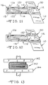
- Fig. 11 it illustrates the initial stage of the method which includes one wrap of the anode-cathode-separator combination around a mandrel 110 of rectangular cross-section.
- cathode 112 is similar to cathode 44' shown in Fig. 6 which is encased or encapsulated in separator material and anode 114 is similar to anode 42 shown in Figs. 7 and 8.
- Fig. 112 is similar to cathode 44' shown in Fig. 6 which is encased or encapsulated in separator material and anode 114 is similar to anode 42 shown in Figs. 7 and 8.
- FIG. 11 illustrates cathode 112 with parts removed to show cathode current collector 115, cathode material 118, cathode lead 120 and separator material 122 enveloping the same in a manner somewhat similar to that of Fig. 6.
- Anode 114 has a lead 126 extending therefrom in a manner similar to that shown in Figs. 7 and 8.
- an insulating layer 130 can be provided around mandrel 110 between the mandrel and the anode-cathode-separator combination.
- Fig. 12 shows the arrangement of Fig. 11 wherein the anode-cathode-separator combination has been wrapped more than once around mandrel 110. A section of the cathode portion wrapped around mandrel 110 has been removed to show the anode portion wrapped around mandrel 110. Once the wrapping is completed, mandrel 110 is removed from the combination.
- lid 24 is welded to casing 12 to provide an hermetic seal in a known manner
- liquid electrolyte such as that disclosed in Patent 4,830,940 is introduced through the fill opening in lid 24 to the subassembly 150, whereupon cap 32 is welded to lid 24 to complete the hermetic seal in a known manner.
- Figs. 14 and 15 show a prismatic, high rate cell 210 including an electrically conductive casing 212 of metal such as stainless steel including a pair of flat-faced sidewalls 214,216 in opposed, substantially mutually parallel relation joined by a curved bottom wall 218.
- a pair of end walls 220,222 meet the sidewalls 214,216 at substantially rounded corners. If desired, end walls 220,222 also could be curved.
- Casing 212 is completed by a conductive lid 224 which is hermetically sealed thereto such as by welding.
- the anode and cathode electrodes together with the separator are provided with a scalloped formation along one edge thereof, as compared to the rectangular shaped anode and cathode electrodes and separator of cell 10 where both the edges are straight.
- anode 250 which, like anode 42 comprises a pair of thin elongated alkali metal or lithium strips 252,254 on opposite surfaces of a screen 256 of metal such as nickel.
- the anode assembly 250 is provided with electrical tabs or leads 258 for making electrical connection thereto.
- anode 250 is formed to include a plurality of scallops 262 along one edge thereof. The scallops 262 are equal in size and degree of curvature, and each scallop 262 has a curvature substantially equal to the curvature of surface 242 of subassembly 240.
- Fig. 17 shows a cathode 270 which, like cathode 44, comprises an elongated strip of cathode active material 272 with a cathode current collector 274 embedded therein, collector 274 being a thin screen of metal such as titanium.
- the cathode assembly 270 is provided with electrical leads or cabs 276 for making electrical connection thereto.
- cathode 270 is formed to include a plurality of scallops 278 along one edge thereof.
- the scallops 278 are equal in size and degree of curvature, and each scallop 278 has a curvature substantially equal to the curvature of surface 242 of subassembly 240.
- cathode 270 when cathode 270 along with the anode and separator are wound to form subassembly 240 in a manner similar to that of subassembly 40, the scallops 278 are substantially in registry with each other.
- cathode 270 can be encapsulated in separator material, or a separate elongated strip of separator material can be provided.
- separacor 286 is formed to include a plurality of scallops 288 along one edge thereof.
- the scallops 288 are equal in size and degree of curvature, and each scallop 288 has a curvature substantially equal to the curvature of surface 242 of subassembly 240.
- separator 286 along with the anode and cathode are wound to form subassembly 240 in a manner similar co that of subassembly 40, the scallops 288 are substantially in registry with each other.
- Manufacture of the cell stack assembly thereof includes, briefly, folding the anode to form a serpentine-like structure, placing individual cathode plates between the folds of the anode structure, and then making electrical connection including welding operations to individual leads of each of the plurality of cathode plates.
- a method of making a solid cathode, liquid electrolyte, alkali metal high rate cell comprising the steps of:
- the present invention provides a solid cathode, liquid electrolyte, alkali metal,high rate cell as claimed in claim 14 wherein a combination of an elongated alkali metal anode and elongated solid cathode with separator therebetween is wound co form an anode-cathode subassembly having a jellyroll type configuration and wherein the combination is shaped so that the resulting sub-assembly has a substantially rectangular cross-section, the shaping of the combination being done either simultaneously with or subsequent to the winding thereof.
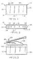
- Figs. 1 and 2 show a prismatic, high rate cell 10 according to the present invention.
- Cell 10 includes an electrically conductive casing 12 of metal such as stainless steel.
- Casing 12 includes a pair of flat-faced sidewalls 14,16 in opposed, substantially mutually parallel relation joined by a bottom wall 18 and a pair of end walls 20,22 which meet the sidewalls 14,16 at substantially rounded corners.
- Casing 12 is completed by a conductive lid 24 which is hermetically sealed thereto such as by welding.
- prismatic it is meant that the cell casing includes flat faces on the side walls, wherein if desired the bottom and end walls can be curved in a manner which will be described.
- the method of the present invention begins by providing a combination of an elongated alkali metal anode, an elongated solid cathode and separator therebetween in a face-to-face relationship.
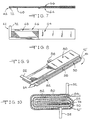
- One such combination is shown in Fig. 9 and includes an elongated lithium anode generally designated 80, an elongated solid cathode generally designated 82 and an elongated separator 84 therebetween in face-to-face relation with and between the anode 80 and cathode 82.
- FIG. 10 illustrates the role of separator strip 90 providing added insulation over the one end edge of cachode 82.
- the opposite end edge of cathode 82 is sealed or protected by folding an extending end portion 102 of separator 84 over the end of cathode 82 in the manner shown in Fig. 10.
- the conduccive casing 212 serves as one electrical terminal of cell 210 in a known manner.
- the opposite polarity terminal of cell 210 is provided by a terminal pin 228 extending outwardly from lid 224 and electrically insulated therefrom by an insulator element 230.
- Lid 224 is provided with a fill opening for supplying liquid electrolyte to the interior of casing 212 in a manner like that described for cell 10, and this opening is sealed closed by a cap or closure 232 welded co lid 224 in a known manner.
- the two prismatic cells 10 and 210 are identical.
- the cell 210 of Figs. 14 and 15 includes an anode-cathode subassembly 240 which is substantially similar to the anode-cathode subassembly 40 of the cell 10, i.e. has a substantially rectangular cross-section, and is provided with a curved surface 242 to accommodate the curved bottom wall 218 of cell casing 212.
- the anode and cathode electrodes together with the separator are provided with a scalloped formation along one edge thereof, as compared to the rectangular shaped anode and cathode electrodes and separator of cell 10 where both the edges are straight.
- anode 250 when anode 250 along with the cathode and separator are wound to form subassembly 240 in a manner similar to that of subassembly 40, the scallops 262 are substantially in registry with each other.
- anode 250 can be encapsulated in separator material, or a separate elongated strip of separator material can be provided.
- cathode 270 when cathode 270 along with the anode and separator are wound to form subassembly 240 in a manner similar to that of subassembly 40, the scallops 278 are substantially in registry with each other.
- cathode 270 can be encapsulated in separator material, or a separate elongated scrip of separator material can be provided.
- anode 250 and cathode 270 are placed in face-to-face relation with the scallops 262 and 278, respectively, in registry with each other. If neither anode 250 nor cathode 270 is encapsulated in separator material, separator strip 286 is sandwiched therebetween with the scallops 288 thereof in registry with the scallops 262 and 278. Then the combination is wound and shaped co have a rectangular cross-section in a manner similar to the embodiment of Figs. 1-13.
Landscapes
- Engineering & Computer Science (AREA)
- Manufacturing & Machinery (AREA)
- Chemical & Material Sciences (AREA)
- Chemical Kinetics & Catalysis (AREA)
- Electrochemistry (AREA)
- General Chemical & Material Sciences (AREA)
- Primary Cells (AREA)
- Secondary Cells (AREA)
- Sealing Battery Cases Or Jackets (AREA)
- Cell Separators (AREA)
- Immobilizing And Processing Of Enzymes And Microorganisms (AREA)
- Preparation Of Compounds By Using Micro-Organisms (AREA)
Abstract
Description
- This invention relates to the art of lithium batteries, and more particularly to a new and improved solid cathode, liquid organic electrolyte lithium battery for delivering high current pulses.
- One area of use of the present invention is a battery for operating an implantable cardiac defibrillator, although the principles of the present invention can be variously applied. The purpose of the implantable defibrillator is to prevent sudden death from lethal arrhythmia, and in operation the device continuously monitors the heart rate of the patient, is able to recognize ventricular fibrillation, and subsequently delivers a high energy shock to defibrillate the heart. In order to power this device, implantable high rate batteries have been developed which have the ability to deliver a current pulse and rapidly recover the open circuit voltage.
- An example of a battery having high capacity, low self-discharge and good pulsing behavior at all levels is shown and described in United States Patent No. 4,830,940. Manufacture of the cell stack assembly thereof includes, briefly, folding the anode to form a serpentine-like structure, placing individual cathode plates between the folds of the anode structure, and then making electrical connection including welding operations to individual leads of each of the plurality of cathode plates.
- It would, therefore, be highly desirable to provide a new and improved high rate battery which reduces the time required to manufacture the cell stack assembly while maintaining the requisite safety and reliability standards in operation.
- EP - A - 0 655 793, which was filed after the priority date of the present application and which designates Germany, France and The Netherlands describes an electrochemical cell in which an anode and a cathode, of a different length to the anode, are wound together in a unidirectional winding such that the winding will fit in a prismatic cell.
- JP - A - 57163965 relates to a battery including an elliptically spiral electrode assembly which may be fitted in an elliptical case.
- It is, therefore, a primary object of the present invention to provide a new and improved solid cathode, liquid electrolyte, alkali metal, high rate battery and method of making the same.
- It is a more particular object of the present invention to provide such a battery and method of making the same wherein the time required to manufacture the cell stack assembly is reduced significantly.
- It is a further object of this invention to provide such a battery and method wherein manufacturing time is reduced while at the same time the requisite safety, performance and reliability standards in battery operation are maintained.
- According to the present invention there is provided a method of making a solid cathode, liquid electrolyte, alkali metal high rate cell comprising the steps of:
- (a) providing a combination of an elongated alkali metal anode, elongated solid cathode and separator therebetween in a face-to-face relationship, the separator preventing direct contact between the anode and the cathode;
- (b) winding the combination to form an anode-cathode subassembly having a jellyroll type configuration;
- (c) shaping the combination so that the resulting sub-assembly has a substantially rectangular cross-section;
- (d) placing the anode-cathode sub-assembly in a conductive cell casing of prismatic shape having opposed flat faces;
- (e) attaching a lead of one of the anode or cathode to the cell casing and connecting a lead of the other of the anode or cathode to an electrical connector means extending through the casing in an insulated manner;
- (f) introducing liquid electrolyte to said anode-cathode sub-assembly in said casing; and
- (g) sealing said casing.
-
- The present invention provides a solid cathode, liquid electrolyte, alkali metal,high rate cell wherein a combination of an elongated alkali metal anode and elongated solid cathode with separator therebetween is wound to form an anode-cathode subassembly having a jellyroll type configuration and wherein the combination is shaped so that the resulting sub-assembly has a substantially rectangular cross-section, the shaping of the combination being done either simultaneously with or subsequent to the winding thereof. The anode-cathode sub-assembly is placed in a conductive cell casing of prismatic shape having opposed flat faces, a lead of either the anode or cathode is attached to the cell casing depending upon whether case positive or case negative electrical configuration is desired and a lead of the other of the anode or cathode is connected to an electrical connector means extending through the casing in an insulated manner. Liquid electrolyte is introduced to the anode-cathode sub-assembly in the casing whereupon the casing then is sealed closed. The foregoing provides a new and improved prismatic high rate battery which significantly reduces the time required to manufacture the cell stack assembly while maintaining the requisite safety and reliability standards in operation.
- The liquid electrolyte is preferably an organic electrolyte.
- The foregoing and additional advantages and characterizing features of the present invention will become clearly apparent upon a reading of the ensuing detailed description together with the included drawings wherein:
-
- Fig. 1 is a side elevational view of a solid cathode, liquid organic electrolyte, alkali metal, high rate battery according to one embodiment the present invention;
- Fig. 2 is a top plan view thereof;
- Fig. 3 is a developed view illustrating one of the final assembly stages in the manufacture of the cell of Figs. 1 and 2;
- Fig. 4 is a top plan view of the cell casing of Fig. 3 with the lid assembly removed to show an anode-cathode subassembly therefor;
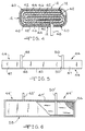
- Fig. 5 is a side elevational view of one form of cathode assembly for the cell of Figs. 1-4;
- Fig. 6 is a side elevational view with parts broken away of another form of cathode assembly for the cell of Figs. 1-4;
- Fig. 7 is a side elevational view of an anode assembly for the cell of Figs. 1-4;
- Fig. 8 is a top plan view of the anode assembly of Fig. 7;
- Fig. 9 is a perspective view illustrating the method of the present invention at a beginning stage chereof;
- Fig. 10 is a top plan view of a cell stack assembly formed by the method of the present invention;
- Fig. 11 is a perspective view with parts removed illustrating the shaping step of the method of the present invention at an initial stage thereof;
- Fig. 12 is a perspective view illustrating the method of Fig. 11 at a subsequent stage thereof;
- Fig. 13 is a diagrammatic view of an alternative mode of shaping in the method of the present invention;
- Fig. 14 is a side elevational view of a solid cathode liquid organic electrolyte alkali metal high rate battery according to another embodiment of the present invention;
- Fig. 15 is a top plan view thereof;
- Fig. 16 is a side elevational view with a portion broken away of an anode assembly for the cell of Figs. 14 and 15;
- Fig. 17 is a side elevational view with a portion broken away of a cathode assembly for the cell of Figs. 14 and 15; and
- Fig. 18 is a side elevational view of a separacor for use in the cell of Figs. 14 and 15.
-
- Figs. 1 and 2 show a prismatic,
high rate cell 10 according to the present invention.Cell 10 includes an electricallyconductive casing 12 of metal such as stainless steel.Casing 12 includes a pair of flat-faced sidewalls bottom wall 18 and a pair ofend walls sidewalls Casing 12 is completed by aconductive lid 24 which is hermetically sealed thereto such as by welding. By prismatic it is meant that the cell casing includes flat faces on the side walls, wherein if desired the bottom and end walls can be curved in a manner which will be described. - The
conductive casing 12 serves as one electrical terminal ofcell 10 in a known manner. The opposite polarity terminal ofcell 10 is provided by aterminal pin 28 extending outwardly fromlid 24 and electrically insulated therefrom by aninsulator element 30.Lid 24 is provided with a fill opening for supplying liquid electrolyte to the interior ofcasing 12 in a manner which will be described, and this opening is sealed closed by a cap orclosure 32 welded tolid 24 in a known manner. - Referring now to Figs. 3 and 4, the
cell 10 of the present invention comprises an anode-cathode subassembly generally designated 40 which is in a jellyroll type configuration as known to those skilled in the art and which additionally, and in accordance with the present invention, is shaped to have a substantially rectangular cross-section. As will be described in detail presently, the jellyroll configuration of the anode-cathode subassembly advantageously simplifies the structure of and reduces the manufacturing time for the anode-cathode subassembly, and the rectangular cross-section of the anode-cathode subassembly enables it to be incorporated in a prismatic cell casing. - Briefly, the anode-
cathode subassembly 40 comprises the combination of an elongatedalkali metal anode 42, an elongatedsolid cathode 44 andseparator 46 therebetween in a face-to-face relationship which combination is wound to form the anode-cathode subassembly 40 of jellyroll type configuration and which combination is shaped according to the present invention to have a substantially rectangular cross-section. One form ofcathode 44 is shown in detail in Fig. 5. - In particular,
cathode 44 comprises abody 47 of cathode active material in the form of an elongated strip having a length many times greater than the width thereof and which is relatively thin. Cathodeactive material 47 can have various forms, and one exemplary material contains silver vanadium oxide. For a more detailed description of this illustrative cathode material and a method of making the same, reference may be made to United States Patent No. 4,830,940 issued May 16, 1989 entitled "Non-Aqueous Lithium Battery", the disclosure of which is hereby incorporated by reference.Cathode 44 further comprises a cathode current collector (not shown in Fig. 5) in the form of a thin sheet of metal screen, for example of titanium, which extends along substantially the entire length and width of thecathode material 47 and is entirely embedded therein. Thecathode 44 shown in Fig. 5 is provided with a pair of tabs orelectrical leads tabs cathode material 46 wheretabs tabs Tabs cathode body 47 and extend outwardly from one side edge ofbody 47 in substantially mutually parallel relation.Tabs tabs cathode body 46. While twotabs Cathode 44 could have only one electrical lead or tab or even more than two, depending upon the size of the electrochemical cell in which thecathode 44 is to be included. - The form of
cathode 44 shown in Fig. 5 is for use in an anode-cathode subassembly wherein a separate strip of separator material is sandwiched between the anode and cathode strips or wherein the anode is encased in separator material. Fig. 6 shows another form of cathode 44' which is encased or encapsulated in separator material. In Fig. 6 components of the cathode assembly which are identical to the components of the cathode assembly 44' shown in Fig. 5 are identified by the same reference numeral provided with a prime designation. Thus cathode assembly 44' in Fig. 6 includes an elongaced, strip-like body 47', a portion of which is broken away in Fig. 6 to show the cathodecurrent collector 54 embedded therein. Cathode 44' is provided with a pair of electrical leads or tabs 48',50'attached to current collector 54' substantially flush with body 47' in a manner similar tocabs cathode 44 shown in Fig. 5. Cathode 44' of Fig. 6 is contained or encased in an envelope of separator material generally designated 58. One method for encasing cathode 44' includes providing a strip of separator material somewhat longer than cathode 44' and twice as wide. The separator strip is folded along the long axis. Cathode 44' is placed into the fold with the side edge thereof opposite extending tabs 48',50' abutting the fold. The three open edges of the separator are bonded by heat sealing which melts the separator and allows the upper layer to bond with the lower layer. A portion of the envelope ofseparator material 58 is broken away in Fig. 6 to show cathode body 47' inside and to show the heat sealed edges ofseparator 58. The material ofseparator 58 is of the type which does not block the flow of ions therethrough, and examples of suitable separator material are polypropylene and polyethylene such as Celgard 2400 separator material. - The
anode 42 ofsubassembly 40 is shown in detail in Figs. 7 and 8 and comprises a pair of elongatedalkali metal elements current collector 68 in the form of a screen of metal such as nickel. In particular,lithium scrip 66 has a length many times the width thereof, andcurrent collector 68 has a length slightly less than the length oflithium strip 66 and a width somewhat less than the width ofscrip 66.Lithium strip 64 extends from one end of theanode assembly 42, i.e. from the right-hand end as viewed in Figs. 7 and 8, and terminates slightly beyond the midpoint of the length ofanode assembly 42. The provision of one lithium anode strip being significantly shorter in length than the other is for a purpose which will be described presently. Theanode assembly 42 is provided with an electrical lead ortab 72 for making electrical connection thereto.Tab 72 is located at one end ofassembly 42, i.e. the end opposite the end having both lithium strips 64,66 and is attached to the exposedcurrent collector 68 such as by spot welding.Tab 72 is disposed in the plane ofanode assembly 42 and extends outwardly from one side edge thereof. - The form of
anode assembly 42 shown in Figs. 7 and 8 is for use in an anode-cathode subassembly wherein a separate strip of separator material is sandwiched between the anode and cathode strips or wherein the cathode is encased in separator material in a manner similar to that of cathode assembly 44' shown in Fig. 6. - The method of the present invention begins by providing a combination of an elongated alkali metal anode, an elongated solid cathode and separator therebetween in a face-to-face relationship. One such combination is shown in Fig. 9 and includes an elongated lithium anode generally designated 80, an elongated solid cathode generally designated 82 and an
elongated separator 84 therebetween in face-to-face relation with and between theanode 80 andcathode 82.Separator 84 is in the form of a strip of suitable separator material such as the aforementioned Celgard 2400 material, having a length about twice that of eitheranode 80 orcathode 82, and in the present illustration is folded aboutcathode 82 so thatcathode 82 is withinseparator 84 as shown in Fig. 9. In other words,separator 84 is folded at a location about mid-way between the ends thereof and so as to be folded endwise ofcathode 82 with thefold 86 ofseparator 84 being adjacent one end ofcathode 82. Alternatively,separator 84 could be folded aboutanode 80 in a similar manner. - In the embodiment of the present invention illustrated in Fig. 9, there is provided an additional
elongated separator 90 of relatively shorter length as compared toseparator 84 and on the end ofcathode 82 withinfold 86 ofseparacor 84.Separator 90 is a strip of suitable material, typically the same material asseparator 84, and serves to provide extra insulation over the edge ofcathode 82 in this embodiment wherein the separate ordiscrete separator strip 84 is provided rather than the cathode being encased in separator material.Separacor 90 is folded at a location about one-quarter of the distance between the ends thereof and so as to be folded endwise ofcathode 82 with the fold 92' ofseparator 90 being adjacent the end ofcathode 82. In the alternative arrangement whereinseparator 84 is folded aboutanode 80,separator 90 likewise would be folded aboutanode 80. - The next step in the method of the present invention is winding the combination to form an anode-cathode subassembly having a jelly roll type or coiled configuration. The combination is wound or rolled in a suitable manner, and one illustrative technique will be described in detail presently. The method of the present invention is characterized by shaping the combination so that the resulting anode-cathode subassembly has a substantially rectangular cross-section. The step of shaping the combination can be performed simultaneously with the step of winding the combination. Alternatively, after the combination is wound or coiled it can be shaped to have the substantially rectangular cross-section. In any event, Fig. 10 shows the anode-cathode subassembly after being wound in a jelly-roll type configuration and shaped to have a substantially rectangular cross-section.
- In particular, and referring to Fig. 10,
anode tab 92 extends from an outermost surface of the anode-cathode subassembly and is available for connection tocell casing 12 in a suitable manner such as by welding. Also, the outer surface of one of the lithium anode strips is exposed around the periphery of the subassembly for contact withcasing 12 to augment the electrical connection ofanode 42 tocell casing 12 in this illustrative case negative electrical configuration. In this embodiment of the present invention,cathode 82 is provided with a single electrical lead ortab 98 which extends from the subassembly for making electrical connection toterminal pin 28 in a manner which will be described. Fig. 10 illustrates the role ofseparator strip 90 providing added insulation over the one end edge ofcathode 82. The opposite end edge ofcathode 82 is sealed or protected by folding an extendingend portion 102 ofseparacor 84 over the end ofcathode 82 in the manner shown in Fig. 10. - Fig. 10 also illustrates the reason for having one of the anode strips, i.e. anode
strip 64, shorter in length than theother anode strip 66 as previously described in connection with Figs. 7 and 8. Around the periphery of the anode-cathode subassembly as shown in Fig. 10 there is only one surface ofcathode 82 available for operative contact withanode 80. Therefore, this portion of the length ofanode 80 requires only one lithium strip. Within the subassembly of Fig. 10 it is seen that opposed surfaces ofcathode 82 are available for operative contact withanode 80 and this therefore requires two lithium strips on opposite surfaces of the anode current collector. This form of anode structure advantageously reduces the amount of lithium required which, in turn, yields savings in cost and size for the resulting cell. - The anode-cathode subassembly shown in Fig. 10 is placed in the
conductive cell casing 12, theleads terminal pin 28, respectively, liquid electrolyte is introduced to the subassembly incasing 12 and the casing is hermetically sealed, all in a manner which will be described in further detail presently. - As previously described, the method of the present invention is characterized by shaping the combination of anode, cathode and separator so that the resulting anode-cathode subassembly has a substantially rectangular cross-section wherein the shaping can be performed simultaneously with winding or coiling the combination or performed after the combination has been wound or coiled. Figs. 11 and 12 illustrate the method of the present invention wherein the step of shaping the combination is performed simultaneously with the step of winding or coiling the combination. One way of carrying out this embodiment of the present invention is by using a mandrel of substantially rectangular configuration, i.e. cross-section, about which the combination is wound.
- Referring first to Fig. 11 it illustrates the initial stage of the method which includes one wrap of the anode-cathode-separator combination around a
mandrel 110 of rectangular cross-section. In the anode-cathode-separator combination shown in Fig. 11,cathode 112 is similar to cathode 44' shown in Fig. 6 which is encased or encapsulated in separator material andanode 114 is similar toanode 42 shown in Figs. 7 and 8. In particular, Fig. 11 illustratescathode 112 with parts removed to show cathode current collector 115,cathode material 118,cathode lead 120 andseparator material 122 enveloping the same in a manner somewhat similar to that of Fig. 6.Anode 114 has a lead 126 extending therefrom in a manner similar to that shown in Figs. 7 and 8. As shown in Fig. 11, an insulatinglayer 130 can be provided aroundmandrel 110 between the mandrel and the anode-cathode-separator combination. - Fig. 12 shows the arrangement of Fig. 11 wherein the anode-cathode-separator combination has been wrapped more than once around
mandrel 110. A section of the cathode portion wrapped aroundmandrel 110 has been removed to show the anode portion wrapped aroundmandrel 110. Once the wrapping is completed,mandrel 110 is removed from the combination. - Thus, Figs. 11 and 12 show the method of the present invention wherein the shaping of the combination to provide an anode-cathode subassembly of substantially rectangular cross-section is performed simultaneously with winding or coiling the combination. Alternatively, the shaping can be performed after the combination has been wound or coiled and this is illustrated diagrammatically in Fig. 13 wherein a previously spirally wound or coiled anode-cathode-
separator combination 140 is placed in a suitable pressing fixture including jaws or pressing members 142,144 which act on opposite surface portions ofcombination 140 to force or shape the combination to have a substantially rectangular cross-section. - As previously described, the anode-cathode subassembly formed by the method of the present invention is placed in the
cell casing 12, and the substantially rectangular cross-section of the subassembly enables it to be properly received in aprismatic casing 12 of the type shown in Figs. 1-3. The anode lead from the subassembly is connected to casing 12 by welding and the exposed grid surface or the anode contacts the inner surface ofcasing 12. Fig. 3 shows an anode-cathode subassembly 150 which has been so placed incasing 12 and where the anode lead (not shown) has been welded to casing 12 as described. The cathode leads, one shown at 152 in Fig. 3 are welded to a connectinglead 154 which, in turn, is welded to anextension 156 ofterminal pin 28 which is insulated fromlid 24 by aninsulator structure 30 in a known manner. Accordingly, the relatively few leads requiring welding operations for making electrical connections and the manner of making the connections result in a significant simplification and reduction in time of this portion of the manufacture of the cell. - After the foregoing operation is completed,
lid 24 is welded to casing 12 to provide an hermetic seal in a known manner, liquid electrolyte such as that disclosed in Patent 4,830,940 is introduced through the fill opening inlid 24 to the subassembly 150, whereupon cap 32 is welded tolid 24 to complete the hermetic seal in a known manner. - Figs. 14 and 15 show a prismatic,
high rate cell 210 including an electricallyconductive casing 212 of metal such as stainless steel including a pair of flat-faced sidewalls 214,216 in opposed, substantially mutually parallel relation joined by acurved bottom wall 218. A pair of end walls 220,222 meet the sidewalls 214,216 at substantially rounded corners. If desired, end walls 220,222 also could be curved. Casing 212 is completed by aconductive lid 224 which is hermetically sealed thereto such as by welding. - The
conductive casing 212 serves as one electrical terminal ofcell 210 in a known manner. The opposite polarity terminal ofcell 210 is provided by a terminal pin 228 extending outwardly fromlid 224 and electrically insulated therefrom by an insulator element 230.Lid 224 is provided with a fill opening for supplying liquid electrolyte to the interior ofcasing 212 in a manner like that described forcell 10, and this opening is sealed closed by a cap orclosure 232 welded tolid 224 in a known manner. - Except for the
curved bottom wall 218 ofcell 210 and theflac bottom wall 18 ofcell 10, the twoprismatic cells cell 10, thecell 210 of Figs. 14 and 15 includes an anode-cathode subassembly 240 which is substantially similar to the anode-cathode subassembly 40 of thecell 10, i.e. has a substantially rectangular cross-section, and is provided with acurved surface 242 to accommodate thecurved bottom wall 218 ofcell casing 212. In order to provide thecurved surface 242 ofsubassembly 240, the anode and cathode electrodes together with the separator are provided with a scalloped formation along one edge thereof, as compared to the rectangular shaped anode and cathode electrodes and separator ofcell 10 where both the edges are straight. - In particular, and referring now to Fig. 16, there is shown an
anode 250 which, likeanode 42 comprises a pair of thin elongated alkali metal or lithium strips 252,254 on opposite surfaces of ascreen 256 of metal such as nickel. Theanode assembly 250 is provided with electrical tabs or leads 258 for making electrical connection thereto. In accordance with this embodiment of the present invention,anode 250 is formed to include a plurality ofscallops 262 along one edge thereof. Thescallops 262 are equal in size and degree of curvature, and eachscallop 262 has a curvature substantially equal to the curvature ofsurface 242 ofsubassembly 240. Thus, whenanode 250 along with the cathode and separator are wound to form subassembly 240 in a manner similar to that ofsubassembly 40, thescallops 262 are substantially in registry with each other. As in the previous embodiment,anode 250 can be encapsulated in separator material, or a separate elongated strip of separator material can be provided. - Fig. 17 shows a
cathode 270 which, likecathode 44, comprises an elongated strip of cathodeactive material 272 with a cathodecurrent collector 274 embedded therein,collector 274 being a thin screen of metal such as titanium. Thecathode assembly 270 is provided with electrical leads orcabs 276 for making electrical connection thereto. In accordance with this embodiment of the present invention,cathode 270 is formed to include a plurality ofscallops 278 along one edge thereof. Thescallops 278 are equal in size and degree of curvature, and eachscallop 278 has a curvature substantially equal to the curvature ofsurface 242 ofsubassembly 240. Thus whencathode 270 along with the anode and separator are wound to form subassembly 240 in a manner similar to that ofsubassembly 40, thescallops 278 are substantially in registry with each other. As in the previous embodiment,cathode 270 can be encapsulated in separator material, or a separate elongated strip of separator material can be provided. - Referring now co Fig. 18 there is shown the
elongated strip 286 of separator material mentioned hereinabove and which is the same material as the separacor incell 10. In accordance with this embodiment of the present invention,separacor 286 is formed to include a plurality ofscallops 288 along one edge thereof. Thescallops 288 are equal in size and degree of curvature, and eachscallop 288 has a curvature substantially equal to the curvature ofsurface 242 ofsubassembly 240. Thus, whenseparator 286 along with the anode and cathode are wound to form subassembly 240 in a manner similar co that ofsubassembly 40, thescallops 288 are substantially in registry with each other. - In order to form
subassembly 240,anode 250 andcathode 270 are placed in face-to-face relation with thescallops anode 250 norcathode 270 is encapsulated in separacor material,separator strip 286 is sandwiched therebetween with thescallops 288 thereof in registry with thescallops - It is therefore apparent that the present invention accomplishes its intended objects. While embodiments of the present invention have been described in detail, that is for the purpose of illustration, not limitation.
- This invention relates to the art of lithium batteries, and more particularly to a new and improved solid cathode, liquid organic electrolyte lithium battery for delivering high current pulses.
- One area of use of the present invention is a battery for operating an implantable cardiac defibrillator, although the principles of the present invention can be variously applied. The purpose of the implantable defibrillator is to prevent sudden death from lethal arrhythmia, and in operation the device continuously monitors the heart rate of the patient, is able to recognize ventricular fibrillation, and subsequently delivers a high energy shock to defibrillate the heart. In order to power this device, implantable high rate batteries have been developed which have the ability to deliver a current pulse and rapidly recover the open circuit voltage.
- An example of a battery having high capacity, low self-discharge and good pulsing behavior at all levels is shown and described in United States Patent No. 4,830,940. Manufacture of the cell stack assembly thereof includes, briefly, folding the anode to form a serpentine-like structure, placing individual cathode plates between the folds of the anode structure, and then making electrical connection including welding operations to individual leads of each of the plurality of cathode plates.
- It would, therefore, be highly desirable to provide a new and improved high rate battery which reduces the time required co manufacture the cell stack assembly while maintaining the requisite safety and reliability standards in operation.
- EP - A - 0 655 793, which was filed after the priority date of the present application and which designates Germany, France and The Netherlands describes an electrochemical cell in which an anode and a cathode, of a different length to the anode, are wound together in a unidirectional winding such that the winding will fit in a prismatic cell.
- JP - A - 57163965 relates to a battery including an elliptically spiral electrode assembly which may be fitted in an elliptical case.
- It is, therefore, a primary object of the present invention to provide a new and improved solid cathode, liquid electrolyte, alkali metal, high rate battery and method of making the same.
- It is a more particular object of the present invention to provide such a battery and method of making the same wherein the time required to manufacture the cell stack assembly is reduced significantly.
- It is a further object of this invention to provide such a battery and method wherein manufacturing time is reduced while at the same time the requisite safety, performance and reliability standards in battery operation are maintained.
- According to the present invention there is provided a method of making a solid cathode, liquid electrolyte, alkali metal high rate cell comprising the steps of:
- (a) providing a combination of an elongated alkali metal anode, elongated solid cathode and separator therebetween in a face-to-face relationship, the separator preventing direct contact between the anode and the cathode;
- (b) winding the combination to form an anode-cathode subassembly having a jellyroll type configuration;
- (c) shaping the combination so that the resulting sub-assembly has a substantially rectangular cross-section;
- (d) placing the anode-cathode sub-assembly in a conductive cell casing of prismatic shape having opposed flat faces;
- (e) attaching a lead of one of the anode or cathode to the cell casing and connecting a lead of the other of the anode or cathode to an electrical connector means extending through the casing in an insulated manner;
- (f) introducing liquid electrolyte to said anode-cathode sub-assembly in said casing; and
- (g) sealing said casing with the proviso that the elongated anode and the elongated cathode and separator therebetween in a face-to-face relationship along substantially each of the entire lengths thereof.
-
- The present invention provides a solid cathode, liquid electrolyte, alkali metal,high rate cell as claimed in
claim 14 wherein a combination of an elongated alkali metal anode and elongated solid cathode with separator therebetween is wound co form an anode-cathode subassembly having a jellyroll type configuration and wherein the combination is shaped so that the resulting sub-assembly has a substantially rectangular cross-section, the shaping of the combination being done either simultaneously with or subsequent to the winding thereof. The anode-cathode sub-assembly is placed in a conductive cell casing of prismatic shape having opposed flat faces, a lead of etcher the anode or cathode is attached to the cell casing depending upon whether case positive or case negative electrical configuration is desired and a lead of the other of the anode or cathode is connected to an electrical connector means extending through the casing in an insulated manner. Liquid electrolyte is introduced to the anode-cathode sub-assembly in the casing whereupon the casing then is sealed closed. The foregoing provides a new and improved prismatic high rate battery which significantly reduces the time required to manufacture the cell stack assembly while maintaining the requisite safety and reliability standards in operation. - The liquid electrolyte is preferably an organic electrolyte.
- The foregoing and additional advantages and characterizing features of the present invention will become clearly apparent upon a reading of the ensuing detailed description together with the included drawings wherein:
-
- Fig. 1 is a side elevational view of a solid cathode, liquid organic electrolyte,alkali metal, high rate battery according to one embodiment the present invention;
- Fig. 2 is a top plan view thereof;
- Fig. 3 is a developed view illustrating one of the final assembly stages in the manufacture of the cell of Figs. 1 and 2;
- Fig. 4 is a top plan view of the cell casing of Fig. 3 with the lid assembly removed to show an anode-cathode subassembly therefor;
- Fig. 5 is a side elevational view of one form of cathode assembly for the cell of Figs. 1-4;
- Fig. 6 is a side elevational view with parts broken away of another form of cathode assembly for the cell of Figs. 1-4;
- Fig. 7 is a side elevational view of an anode assembly for the cell of Figs. 1-4;
- Fig. 8 is a top plan view of the anode assembly of Fig. 7;
- Fig. 9 is a perspective view illustrating the method of the present invention at a beginning stage thereof;
- Fig. 10 is a cop plan view of a cell stack assembly formed by the method of the present invention;
- Fig. 11 is a perspective view with parts removed illustrating the shaping step of the method of the present invention at an initial stage thereof;
- Fig. 12 is a perspective view illustrating the method of Fig. 11 at a subsequent stage thereof;
- Fig. 13 is a diagrammatic view of an alternative mode of shaping in the method of the present invention;
- Fig. 14 is a side elevational view of a solid cathode liquid organic electrolyte alkali metal high rate battery according to another embodiment of the present invention;
- Fig. 15 is a top plan view thereof;
- Fig. 16 is a side elevational view with a portion broken away of an anode assembly for the cell of Figs. 14 and 15;
- Fig. 17 is a side elevational view with a portion broken away of a cathode assembly for the cell of Figs. 14 and 15; and
- Fig. 18 is a side elevational view of a separator for use in the cell of Figs. 14 and 15.
-
- Figs. 1 and 2 show a prismatic,
high rate cell 10 according to the present invention.Cell 10 includes an electricallyconductive casing 12 of metal such as stainless steel.Casing 12 includes a pair of flat-faced sidewalls bottom wall 18 and a pair ofend walls sidewalls Casing 12 is completed by aconductive lid 24 which is hermetically sealed thereto such as by welding. By prismatic it is meant that the cell casing includes flat faces on the side walls, wherein if desired the bottom and end walls can be curved in a manner which will be described. - The
conductive casing 12 serves as one electrical terminal ofcell 10 in a known manner. The opposite polarity terminal ofcell 10 is provided by aterminal pin 28 extending outwardly fromlid 24 and electrically insulated therefrom by aninsulator element 30.Lid 24 is provided with a fill opening for supplying liquid electrolyte to the interior of casing 12 in a manner which will be described, and this opening is sealed closed by a cap orclosure 32 welded tolid 24 in a known manner. - Referring now to Figs. 3 and 4, the
cell 10 of the present invention comprises an anode-cathode subassembly generally designated 40 which is in a jellyroll type configuration as known to those skilled in the art and which additionally, and in accordance with the present invention, is shaped to have a substantially rectangular cross-section. As will be described in detail presently, the jellyroll configuration of the anode-cathode subassembly advantageously simplifies the structure of and reduces the manufacturing time for the anode-cathode subassembly, and the rectangular cross-section of the anode-cathode subassembly enables it to be incorporated in a prismacic cell casing. - Briefly, the anode-
cathode subassembly 40 comprises the combination of an elongatedalkali metal anode 42, an elongacedsolid cachode 44 andseparator 46 therebetween in a face-to-face relationship which combination is wound to form the anode-cathode subassembly 40 of jellyroll type configuration and which combination is shaped according to the present invention to have a substantially rectangular cross-section. One form ofcathode 44 is shown in detail in Fig. 5. - In particular,
cathode 44 comprises abody 47 of cathode active material in the form of an elongated strip having a length many times greater than the width thereof and which is relatively thin. Cathodeactive material 47 can have various forms, and one exemplary material contains silver vanadium oxide. For a more detailed description of this illustrative cathode material and a method of making the same, reference may be made to United States Patent No. 4,830,940 issued May 16, 1989 entitled "Non- Aqueous Lithium Battery", the disclosure of which is hereby incorporated by reference.Cathode 44 further comprises a cathode current collector (not shown in Fig. 5) in the form of a thin sheet of metal screen, for example of titanium, which extends along substantially the entire length and width of thecathode material 47 and is entirely embedded therein. Thecathode 44 shown in Fig. 5 is provided with a pair of tabs orelectrical leads tabs cathode material 46 wheretabs tabs Tabs cathode body 47 and extend outwardly from one side edge ofbody 47 in substantially mutually parallel relation.Tabs tabs cathode body 46. While twotabs Cathode 44 could have only one electrical lead or tab or even more than two, depending upon the size of the electrochemical cell in which thecathode 44 is to be included. - The form of
cathode 44 shown in Fig. 5 is for use in an anode-cathode subassembly wherein a separate strip of separator material is sandwiched between the anode and cachode strips or wherein the anode is encased in separator material. Fig. 6 shows another form of cathode 44' which is encased or encapsulated in separator material. In Fig. 6 components of the cathode assembly which are identical to the components of the cathode assembly 44' shown in Fig. 5 are identified by the same reference numeral provided with a prime designation. Thus cathode assembly 44' in Fig. 6 includes an elongaced, strip-like body 47', a portion of which is broken away in Fig. 6 to show the cathodecurrent collector 54 embedded therein. Cathode 44' is provided with a pair of electrical leads or tabs 48',50'attached to current collector 54' substantially flush with body 47' in a manner similar totabs cathode 44 shown in Fig. 5. Cathode 44' of Fig. 6 is contained or encased in an envelope of separator macerial generally designated 58. One method for encasing cachode 44' includes providing a strip of separator material somewhat longer than cathode 44' and twice as wide. The separator strip is folded along the long axis. Cathode 44' is placed into the fold with the side edge thereof opposite extending tabs 48',50' abutting the fold. The three open edges of the separator are bonded by heat sealing which melts the separator and allows the upper layer to bond with the lower layer. A portion of the envelope orseparator material 58 is broken away in Fig. 6 to show cathode body 47' inside and to show the heat sealed edges ofseparator 58. The material ofseparator 58 is of the type which does not block the flow of ions therethrough, and examples of suitable separator material are polypropylene and polyethylene such as Celgard 2400 separator material. - The
anode 42 ofsubassembly 40 is shown in detail in Figs. 7 and 8 and comprises a pair of elongatedalkali metal elements current collector 68 in the form of a screen of mecal such as nickel. In particular,lithium strip 66 has a length many times the width thereof, andcurrent collector 68 has a length slightly less than the length oflithium strip 66 and a width somewhat less than the width ofstrip 66.Lithium strip 64 extends from one end of theanode assembly 42, i.e. from the right-hand end as viewed in Figs. 7 and 8, and terminates slightly beyond the midpoint of the length ofanode assembly 42. The provision of one lithium anode strip being significantly shorter in length than the other is for a purpose which will be described presently. Theanode assembly 42 is provided with an electrical lead ortab 72 for making electrical connection thereto.Tab 72 is located at one end ofassembly 42, i.e. the end opposite the end having both lithium strips 64,66 and is attached to the exposedcurrent collector 68 such as by spot welding.Tab 72 is disposed in the plane ofanode assembly 42 and extends outwardly from one side edge thereof. - The form of
anode assembly 42 shown in Figs. 7 and 8 is for use in an anode-cathode subassembly wherein a separate strip of separator material is sandwiched between the anode and cathode strips or wherein the cathode is encased in separator material in a manner similar to that of cathode assembly 44' shown in Fig. 6. - The method of the present invention begins by providing a combination of an elongated alkali metal anode, an elongated solid cathode and separator therebetween in a face-to-face relationship. One such combination is shown in Fig. 9 and includes an elongated lithium anode generally designated 80, an elongated solid cathode generally designated 82 and an
elongated separator 84 therebetween in face-to-face relation with and between theanode 80 andcathode 82.Separator 84 is in the form of a strip of suitable separator material such as the aforementioned Celgard 2400 material, having a length about twice that of eitheranode 80 orcathode 82, and in the present illustration is folded aboutcathode 82 so thatcathode 82 is withinseparator 84 as shown in Fig. 9. In other words,separator 84 is folded at a location about mid-way between the ends thereof and so as to be folded endwise ofcathode 82 with thefold 86 ofseparator 84 being adjacent one end ofcathode 82. Alternatively,separator 84 could be folded aboutanode 80 in a similar manner. - In the embodiment of the present invention illustrated in Fig. 9, there is provided an additional
elongated separator 90 of relatively shorter length as compared toseparator 84 and on the end ofcathode 82 withinfold 86 ofseparator 84.Separator 90 is a strip of suitable material, typically the same material asseparator 84, and serves to provide extra insulation over the edge ofcathode 82 in this embodiment wherein the separate ordiscrete separator strip 84 is provided rather than the cathode being encased in separator material.Separator 90 is folded at a location about one-quarter of the distance between the ends thereof and so as to be folded endwise ofcathode 82 with the fold 92' ofseparator 90 being adjacent the end ofcathode 82. In the alternative arrangement whereinseparator 84 is folded aboutanode 80,separator 90 likewise would be folded aboutanode 80. - The next step in the method of the present invention is winding the combination to form an anode-cathode subassembly having a jelly roll type or coiled configuration. The combination is wound or rolled in a suitable manner, and one illustrative technique will be described in detail presently. The method of the present invention is characterized by shaping the combination so that the resulting anode-cathode subassembly has a substantially rectangular cross-section. The step of shaping the combination can be performed simultaneously with the step of winding the combination. Alternatively, after the combination is wound or coiled it can be shaped to have the substantially rectangular cross-section. In any event, Fig. 10 shows the anode-cathode subassembly after being wound in a jelly-roll type configuration and shaped to have a substantially rectangular cross-section.
- In particular, and referring to Fig. 10,
anode tab 92 extends from an outermost surface of the anode-cathode subassembly and is available for connection tocell casing 12 in a suitable manner such as by welding. Also, the outer surface of one of the lithium anode strips is exposed around the periphery of the subassembly for contact withcasing 12 to augment the electrical connection ofanode 42 tocell casing 12 in this illustrative case negative electrical configuration. In this embodiment of the present invention,cathode 82 is provided with a single electrical lead ortab 98 which extends from the subassembly for making electrical connection toterminal pin 28 in a manner which will be described. Fig. 10 illustrates the role ofseparator strip 90 providing added insulation over the one end edge ofcachode 82. The opposite end edge ofcathode 82 is sealed or protected by folding an extendingend portion 102 ofseparator 84 over the end ofcathode 82 in the manner shown in Fig. 10. - Fig. 10 also illustrates the reason for having one of the anode strips, i.e. anode
strip 64, shorter in length than theother anode strip 66 as previously described in connection with Figs. 7 and 8. Around the periphery of the anode-cathode subassembly as shown in Fig. 10 there is only one surface ofcathode 82 available for operative contact withanode 80. Therefore, this portion of the length ofanode 80 requires only one lithium strip. Within the subassembly of Fig. 10 it is seen that opposed surfaces ofcathode 82 are available for operative contact withanode 80 and this therefore requires two lithium strips on opposite surfaces of the anode current collector. This form of anode structure advantageously reduces the amount of lithium required which, in turn, yields savings in cost and size for the resulting cell. - The anode-cathode subassembly shown in Fig. 10 is placed in the
conductive cell casing 12, theleads terminal pin 28, respectively, liquid electrolyte is introduced to the subassembly incasing 12 and the casing is hermetically sealed, all in a manner which will be described in further detail presently. - As previously described, the method of the present invention is characterized by shaping the combination of anode, cathode and separator so that the resulting anode-cathode subassembly has a substantially rectangular cross-section wherein the shaping can be performed simultaneously with winding or coiling the combination or performed after the combination has been wound or coiled. Figs. 11 and 12 illustrate the method of the present invention wherein the step of shaping the combination is performed simultaneously with the step of winding or coiling the combination. One way of carrying out this embodiment of the present invention is by using a mandrel of substantially rectangular configuration, i.e. cross-section, about which the combination is wound.
- Referring first to Fig. 11 it illustrates the initial stage of the method which includes one wrap of the anode-cathode-separator combination around a
mandrel 110 of rectangular cross-section. In the anode-cathode-separator combination shown in Fig. 11,cathode 112 is similar to cathode 44' shown in Fig. 6 which is encased or encapsulated in separator material andanode 114 is similar toanode 42 shown in Figs. 7 and 8. In particular, Fig. 11 illustratescathode 112 with parts removed to show cathode current collector 115,cathode material 118,cathode lead 120 andseparator material 122 enveloping the same in a manner somewhat similar to that of Fig. 6.Anode 114 has a lead 126 extending therefrom in a manner similar to that shown in Figs. 7 and 8. As shown in Fig. 11, an insulatinglayer 130 can be provided aroundmandrel 110 between the mandrel and the anode-cathode-separator combination. - Fig. 12 shows the arrangement of Fig. 11 wherein the anode-cathode-separator combination has been wrapped more than once around
mandrel 110. A section of the cathode portion wrapped aroundmandrel 110 has been removed to show the anode portion wrapped aroundmandrel 110. Once the wrapping is completed,mandrel 110 is removed from the combination. - Thus, Figs. 11 and 12 show the method of the present invention wherein the shaping of the combination to provide an anode-cathode subassembly of substantially rectangular cross-section is performed simultaneously with winding or coiling the combination. Alternatively, the shaping can be performed after the combination has been wound or coiled and this is illustrated diagrammatically in Fig. 13 wherein a previously spirally wound or coiled anode-cathode-
separator combination 140 is placed in a suitable pressing fixture including jaws or pressing members 142,144 which act on opposite surface portions ofcombination 140 to force or shape the combination to have a substantially rectangular cross-section. - As previously described, the anode-cathode subassembly formed by the method of the present invention is placed in the
cell casing 12, and the substantially rectangular cross-section of the subassembly enables it to be properly received in aprismatic casing 12 of the type shown in Figs. 1-3. The anode lead from the subassembly is connected to casing 12 by welding and the exposed grid surface of the anode contacts the inner surface ofcasing 12. Fig. 3 shows an anode-cathode subassembly 150 which has been so placed incasing 12 and where the anode lead (not shown) has been welded to casing 12 as described. The cathode leads, one shown at 152 in Fig. 3 are welded to a connectinglead 154 which, in turn, is welded to anextension 156 ofterminal pin 28 which is insulated fromlid 24 by aninsulator structure 30 in a known manner. Accordingly, the relatively few leads requiring welding operations for making electrical connections and the manner of making the connections result in a significant simplification and reduction in time of this portion of the manufacture of the cell. - After the foregoing operation is completed,
lid 24 is welded to casing 12 to provide an hermetic seal in a known manner, liquid electrolyte such as that disclosed in Patent 4,830,940 is introduced through the fill opening inlid 24 to the subassembly 150, whereupon cap 32 is welded tolid 24 to complete the hermetic seal in a known manner. - Figs. 14 and 15 show a prismatic,
high race cell 210 including an electricallyconduccive casing 212 of metal such as stainless steel including a pair of flat-faced sidewalls 214,216 in opposed, substantially mutually parallel relation joined by acurved bottom wall 218. A pair of end walls 220,222 meet the sidewalls 214,216 at substantially rounded corners. If desired, end walls 220,222 also could be curved. Casing 212 is completed by aconductive lid 224 which is hermetically sealed thereto such as by welding. - The
conduccive casing 212 serves as one electrical terminal ofcell 210 in a known manner. The opposite polarity terminal ofcell 210 is provided by a terminal pin 228 extending outwardly fromlid 224 and electrically insulated therefrom by an insulator element 230.Lid 224 is provided with a fill opening for supplying liquid electrolyte to the interior ofcasing 212 in a manner like that described forcell 10, and this opening is sealed closed by a cap orclosure 232 weldedco lid 224 in a known manner. - Except for the
curved bottom wall 218 ofcell 210 and theflat bottom wall 18 ofcell 10, the twoprismatic cells cell 10, thecell 210 of Figs. 14 and 15 includes an anode-cathode subassembly 240 which is substantially similar to the anode-cathode subassembly 40 of thecell 10, i.e. has a substantially rectangular cross-section, and is provided with acurved surface 242 to accommodate thecurved bottom wall 218 ofcell casing 212. In order to provide thecurved surface 242 ofsubassembly 240, the anode and cathode electrodes together with the separator are provided with a scalloped formation along one edge thereof, as compared to the rectangular shaped anode and cathode electrodes and separator ofcell 10 where both the edges are straight. - In particular, and referring now to Fig. 16, there is shown an
anode 250 which, likeanode 42 comprises a pair of thin elongated alkali metal or lithium strips 252,254 on opposite surfaces of ascreen 256 of metal such as nickel. Theanode assembly 250 is provided with electrical tabs or leads 258 for making electrical connection thereto. In accordance with this embodiment of the present invention,anode 250 is formed to include a plurality ofscallops 262 along one edge thereof. Thescallops 262 are equal in size and degree of curvature, and eachscallop 262 has a curvature substantially equal to the curvature ofsurface 242 ofsubassembly 240. Thus, whenanode 250 along with the cathode and separator are wound to form subassembly 240 in a manner similar to that ofsubassembly 40, thescallops 262 are substantially in registry with each other. As in the previous embodiment,anode 250 can be encapsulated in separator material, or a separate elongated strip of separator material can be provided. - Fig. 17 shows a
cathode 270 which, likecathode 44, comprises an elongated strip of cathodeactive material 272 with a cathodecurrent collector 274 embedded therein,collector 274 being a thin screen of metal such as titanium. Thecathode assembly 270 is provided with electrical leads ortabs 276 for making electrical connection thereto. In accordance with this embodiment of the present invention,cathode 270 is formed to include a plurality ofscallops 278 along one edge thereof. Thescallops 278 are equal in size and degree of curvature, and eachscallop 278 has a curvature substantially equal to the curvature ofsurface 242 ofsubassembly 240. Thus whencathode 270 along with the anode and separator are wound to form subassembly 240 in a manner similar to that ofsubassembly 40, thescallops 278 are substantially in registry with each other. As in the previous embodiment,cathode 270 can be encapsulated in separator material, or a separate elongated scrip of separator material can be provided. - Referring now to Fig. 18 there is shown the
elongated strip 286 of separator material mentioned hereinabove and which is the same material as the separator incell 10. In accordance with this embodiment of the present invention,separator 286 is formed to include a plurality ofscallops 288 along one edge thereof. Thescallops 288 are equal in size and degree of curvature, and eachscallop 288 has a curvature substantially equal to the curvature ofsurface 242 ofsubassembly 240. Thus, whenseparator 286 along with the anode and cathode are wound to form subassembly 240 in a manner similar to that ofsubassembly 40, thescallops 288 are substantially in registry with each other. - In order to form
subassembly 240,anode 250 andcathode 270 are placed in face-to-face relation with thescallops anode 250 norcathode 270 is encapsulated in separator material,separator strip 286 is sandwiched therebetween with thescallops 288 thereof in registry with thescallops - It is therefore apparent that the present invention accomplishes its intended objects. While embodiments of the present invention have been described in detail, that is for the purpose of illustration, not limitation.
Claims (20)
- A method of making a solid cathode, liquid electrolyte, alkali metal high rate cell comprising the steps of:(a) providing a combination of an elongated alkali metal anode, elongated solid cathode and separator therebetween in a face-to-face relationship, the separator preventing direct contact between the anode and the cathode;(b) winding the combination to form an anode-cathode subassembly having a jellyroll type configuration;(c) shaping the combination so that the resulting sub-assembly has a substantially rectangular cross-section;(d) placing the anode-cathode sub-assembly in a conductive cell casing of prismatic shape having opposed flat faces;(e) attaching a lead of one of the anode or cathode to the cell casing and connecting a lead of the other of the anode or cathode to an electrical connector means extending through the casing in an insulated manner;(f) introducing liquid electrolyte to said anode-cathode sub-assembly in said casing; and(g) sealing said casing.
- The method according to Claim 1, wherein said step of shaping the combination is performed simultaneously with said step of winding the combination.
- The method according to Claim 2, wherein said step of winding the combination is performed by using a mandrel of substantially rectangular configuration about which the combination is wound.
- The method according to Claim 1, wherein said step of shaping the combination is performed subsequent to said step of winding the combination.
- The method according to Claim 4, wherein said step of shaping comprises pressing the combination into a shape having a substantially rectangular cross-section.
- The method according to any one of claims 1 to 5, wherein said step of providing the anode and cachode with separacor therebetween comprises encasing at least one of the anode and cathode in separator material.
- The method according to claim 6, wherein both of the anode and cathode are encased in separator material.
- The method according to any one of claims 1 to 5, wherein said step of providing the anode and cathode with separator therebetween comprises providing an elongated separator in face-to-face relation with and between the anode and cathode.
- The method according to claim 8, wherein said elongated separator has a length greater than either of said anode or cathode and is folded about said anode or cathode so that said anode or cathode is within said folded separator.
- The method according to claim 9, wherein said separator is folded endwise of said anode or cathode with the fold thereof adjacent one end of said anode or cathode.
- The method according to claim 10, further including providing an additional elongaced separator of relatively short length on said end of said anode or cathode and within said separator of greater length.
- The method according to claim 1, wherein said casing has a curved wall between the opposed flat faces thereof and wherein said anode-cathode subassembly is formed to have a curved surface which conforms to said curved wall of said casing.
- The method according to Claim 12, wherein each of said anode, cathode and separator is provided with a plurality of scallops along one edge thereof wherein each of said scallops has a curvature corresponding to said curved surface of said anode-cathode subassembly.
- A solid cathode liquid electrolyte alkali metal high rate cell comprising:(a) a casing of electrically conductive material and of prismatic shape having opposed flat faces;(b) an alkali metal anode and a solid cathode wound in a jellyroll type configuration and shaped in a substantially rectangular cross-section to provide an anode-cathode subassembly which is contained in the casing;(c) a separator located between the anode and the cathode to prevent direct contact therebetween;(d) a non-aqueous liquid electrolyte in said casing and operatively contacting said anode and said cathode;(e) means for electrically contacting one of said anode or cathode to said casing;(f) means for electrically connecting the other of said anode or cathode to an electrical connector means extending through said casing in an insulated manner; and(g) means for hermetically sealing said casing.
- A cell according to Claim 14, wherein said anode is of lithium.
- A cell according to Claim 14 or 15, wherein the said anode-cathode subassembly is provided by an elongated anode and an elongated cathode having a separator therebetween and wound into said jellyroll configuration.
- A cell according to any one of claims 14 to 16, wherein said anode is connected electrically to said casing to provide a cell of case negative electrical configuration.
- A cell according to any one of claims 14 to 17, wherein said casing has a curved wall between the opposed flat faces thereof and wherein said anode-cathode subassembly has a curved surface which conforms to said curved wall of said casing.
- A cell according to claim 18, wherein each of said anode and cathode has a plurality of scallops along one edge thereof wherein each of said scallops has a curvature corresponding to said curved surface of said anode-cathode subassembly.
- A cell according to claim 19, further including an elongated separator between said anode and cathode and having a plurality of scallops along one edge thereof wherein each of said scallops has a curvature corresponding to said curved surface of said anode-cathode subassembly.
Applications Claiming Priority (2)
| Application Number | Priority Date | Filing Date | Title |
|---|---|---|---|
| US08/205,874 US5549717A (en) | 1994-03-03 | 1994-03-03 | Method of making prismatic cell |
| US205874 | 1998-12-04 |
Publications (2)
| Publication Number | Publication Date |
|---|---|
| EP0670605A1 EP0670605A1 (en) | 1995-09-06 |
| EP0670605B1 true EP0670605B1 (en) | 2002-01-09 |
Family
ID=22764008
Family Applications (1)
| Application Number | Title | Priority Date | Filing Date |
|---|---|---|---|
| EP95301341A Expired - Lifetime EP0670605B1 (en) | 1994-03-03 | 1995-03-02 | Prismatic high rate cell |
Country Status (6)
| Country | Link |
|---|---|
| US (1) | US5549717A (en) |
| EP (1) | EP0670605B1 (en) |
| JP (1) | JP3737835B2 (en) |
| AT (1) | ATE211858T1 (en) |
| AU (1) | AU705228B2 (en) |
| DE (1) | DE69524894T2 (en) |
Families Citing this family (83)
| Publication number | Priority date | Publication date | Assignee | Title |
|---|---|---|---|---|
| US6893772B2 (en) * | 1993-11-19 | 2005-05-17 | Medtronic, Inc. | Current collector for lithium electrode |
| ES2135012T3 (en) * | 1994-05-30 | 1999-10-16 | Canon Kk | RECHARGEABLE BATTERIES. |
| JPH08203539A (en) * | 1994-12-13 | 1996-08-09 | Pioneer Electron Corp | Laminated type battery |
| JP3005493B2 (en) * | 1997-04-24 | 2000-01-31 | 日本電気株式会社 | Method for manufacturing prismatic battery |
| US6040082A (en) * | 1997-07-30 | 2000-03-21 | Medtronic, Inc. | Volumetrically efficient battery for implantable medical devices |
| US6951576B1 (en) * | 1997-10-21 | 2005-10-04 | Wilson Greatbatch Ltd. | Wound element electrode assembly design for use in prismatic case electrochemical cells |
| EP0973211A4 (en) * | 1997-11-07 | 2004-05-26 | Sony Corp | SQUARE CLOSED BATTERY |
| US6238819B1 (en) | 1998-01-23 | 2001-05-29 | Stork, N.V. | Metal foam support, electrode and method of making same |
| US5958088A (en) * | 1998-03-04 | 1999-09-28 | Duracell, Inc. | Prismatic cell construction |
| US6001504A (en) * | 1998-03-11 | 1999-12-14 | Duracell Inc. | Prismatic battery housing |
| US6445948B1 (en) | 1998-04-03 | 2002-09-03 | Medtronic, Inc. | Implantable medical device having a substantially flat battery |
| US6459566B1 (en) | 1998-06-24 | 2002-10-01 | Medtronic, Inc. | Implantable medical device having flat electrolytic capacitor with laser welded cover |
| US6190426B1 (en) | 1998-12-17 | 2001-02-20 | Moltech Corporation | Methods of preparing prismatic cells |
| KR100337539B1 (en) * | 1998-12-24 | 2002-07-18 | 성재갑 | Lithium ion battery using square cans containing cotton containing depressions |
| US6678559B1 (en) | 1999-03-23 | 2004-01-13 | Medtronic, Inc. | Implantable medical device having a capacitor assembly with liner |
| KR100289542B1 (en) * | 1999-04-09 | 2001-05-02 | 김순택 | Method for manufacturing lithium secondary battery of prismatic type |
| WO2001039294A2 (en) | 1999-11-23 | 2001-05-31 | Moltech Corporation | Methods of preparing electrochemical cells |
| US7066971B1 (en) | 1999-11-23 | 2006-06-27 | Sion Power Corporation | Methods of preparing electrochemical cells |
| US6635381B2 (en) * | 2000-05-11 | 2003-10-21 | Wilson Greatbatch Ltd. | Electrochemical lithium ion secondary cell having a scalloped electrode assembly |
| US6488721B1 (en) | 2000-06-09 | 2002-12-03 | Moltech Corporation | Methods of preparing electrochemical cells |
| US6509588B1 (en) | 2000-11-03 | 2003-01-21 | Cardiac Pacemakers, Inc. | Method for interconnecting anodes and cathodes in a flat capacitor |
| US7163762B2 (en) | 2000-11-21 | 2007-01-16 | Sony Corporation | Polymer electrolyte battery and method of producing same |
| US6716552B2 (en) * | 2000-11-30 | 2004-04-06 | Celgard Inc. | Secondary lithium battery construction for improved heat transfer |
| US6622046B2 (en) | 2001-05-07 | 2003-09-16 | Medtronic, Inc. | Subcutaneous sensing feedthrough/electrode assembly |
| US6650942B2 (en) | 2001-05-30 | 2003-11-18 | Medtronic, Inc. | Implantable medical device with dual cell power source |
| US7191008B2 (en) | 2001-05-30 | 2007-03-13 | Medtronic, Inc. | Implantable medical device with a dual power source |
| US7337001B2 (en) * | 2001-05-30 | 2008-02-26 | Medtronic, Inc. | Implantable medical device and method with a dual power source incorporating electrolyte additive 2,2,2-trifluoroacetamide |
| US7807300B2 (en) * | 2006-01-31 | 2010-10-05 | Medtronic, Inc. | Resistance-stabilizing additives for electrolyte |
| ATE460753T1 (en) * | 2001-07-19 | 2010-03-15 | Greatbatch Ltd | CURVED HOUSING FOR AN IMPLANTABLE MEDICAL DEVICE |
| US6977124B2 (en) | 2001-07-19 | 2005-12-20 | Wilson Greatbatch Technologies, Inc. | Contoured casing for an electrochemical cell |
| US20040054425A1 (en) * | 2002-05-13 | 2004-03-18 | Glenn Elmore | Method and apparatus for information conveyance and distribution |
| US6881516B2 (en) * | 2002-09-30 | 2005-04-19 | Medtronic, Inc. | Contoured battery for implantable medical devices and method of manufacture |
| US20040064163A1 (en) * | 2002-09-30 | 2004-04-01 | Aamodt Paul B. | Contoured battery for implantable medical devices and method of manufacture |
| US8065006B2 (en) * | 2002-09-30 | 2011-11-22 | Medtronic, Inc. | Electrochemical cell for implantable medical devices |
| US20040062985A1 (en) | 2002-09-30 | 2004-04-01 | Aamodt Paul B. | Contoured battery for implantable medical devices and method of manufacture |
| US7479349B2 (en) | 2002-12-31 | 2009-01-20 | Cardiac Pacemakers, Inc. | Batteries including a flat plate design |
| US7951479B2 (en) * | 2005-05-11 | 2011-05-31 | Cardiac Pacemakers, Inc. | Method and apparatus for porous insulative film for insulating energy source layers |
| US8691418B2 (en) * | 2003-02-07 | 2014-04-08 | Cardiac Pacemakers, Inc. | Insulative member on battery cathode |
| US20040161671A1 (en) * | 2003-02-13 | 2004-08-19 | Medtronic, Inc. | Liquid electrolyte for an electrochemical cell |
| US7273674B1 (en) | 2003-02-27 | 2007-09-25 | Greatbatch Ltd. | Primary electrochemical cell having scalloped electrodes |
| US7209784B2 (en) * | 2003-03-31 | 2007-04-24 | Medtronic, Inc. | High power implantable battery with improved safety and method of manufacture |
| US8027728B2 (en) * | 2003-03-31 | 2011-09-27 | Medtronic, Inc. | High power implantable battery with improved safety and method of manufacture |
| JP4846984B2 (en) * | 2003-07-01 | 2011-12-28 | パナソニック株式会社 | Square cylindrical battery and method for manufacturing the same |
| US8945753B2 (en) * | 2005-01-26 | 2015-02-03 | Medtronic, Inc. | Implantable battery having thermal shutdown separator |
| US20060166088A1 (en) * | 2005-01-26 | 2006-07-27 | Hokanson Karl E | Electrode connector tabs |
| US7556886B2 (en) * | 2005-03-31 | 2009-07-07 | Medtronic, Inc. | Hinged electrode cup and methods of fabrication for medical grade electrochemical cells |
| US7544220B2 (en) * | 2005-03-31 | 2009-06-09 | Medtronic, Inc. | Welding methods and apparatus for batteries |
| US7718027B2 (en) * | 2005-05-11 | 2010-05-18 | Cardiac Pacemakers, Inc. | Method and apparatus for concurrent welding and excise of battery separator |
| US20070077488A1 (en) * | 2005-10-04 | 2007-04-05 | Kaimin Chen | Power capability of a cathode |
| US7901808B2 (en) | 2005-11-02 | 2011-03-08 | Cardiac Pacemakers, Inc. | System and method for sealing battery separator |
| US7824805B2 (en) * | 2006-01-17 | 2010-11-02 | Medtronic, Inc. | Implantable medical device battery |
| US20070176151A1 (en) * | 2006-01-31 | 2007-08-02 | Kaimin Chen | Electrolyte additive for performance stability of batteries |
| US8883354B2 (en) * | 2006-02-15 | 2014-11-11 | Optodot Corporation | Separators for electrochemical cells |
| US7869868B2 (en) | 2007-01-11 | 2011-01-11 | Medtronic, Inc. | Diverse capacitor packaging for maximizing volumetric efficiency for medical devices |
| US20090197170A1 (en) * | 2008-01-31 | 2009-08-06 | Viavattine Joseph J | Maximization of active material to collector interfacial area |
| RU2513988C2 (en) | 2009-05-26 | 2014-04-27 | Оптодот Корпорейшн | Battery having electrodes in form of coating deposited directly on nanoporous separators |
| CN102318128B (en) * | 2010-01-13 | 2014-05-07 | 松下电器产业株式会社 | Lithium ion secondary battery and production method for same |
| US9054387B2 (en) | 2010-04-07 | 2015-06-09 | Medtronic, Inc. | Electrode assembly including mandrel having removable portion |
| US8685557B2 (en) | 2010-04-07 | 2014-04-01 | Medtronic, Inc. | Electrode assembly including mandrel having a removable portion |
| PL2596538T3 (en) | 2010-07-19 | 2019-06-28 | Optodot Corporation | Separators for electrochemical cells |
| US9299971B2 (en) | 2010-10-06 | 2016-03-29 | Medtronic, Inc. | Common carrier for the integrated mandrel battery assembly |
| US8832914B2 (en) | 2010-10-06 | 2014-09-16 | Medtronic, Inc | Coiling device for making an electrode assembly and methods of use |
| US9083053B2 (en) | 2011-12-21 | 2015-07-14 | Medtronic, Inc. | Through weld interconnect joint |
| US9005802B2 (en) | 2011-12-21 | 2015-04-14 | Medtronic, Inc. | Electrode assembly with hybrid weld |
| KR101617495B1 (en) * | 2013-03-04 | 2016-05-03 | 주식회사 엘지화학 | Method for Preparing a Jelly-Roll Type Electrode Assembly and a Secondary Battery |
| WO2014179355A1 (en) | 2013-04-29 | 2014-11-06 | Madico, Inc. | Nanoporous composite separators with increased thermal conductivity |
| DE102013225350A1 (en) * | 2013-12-10 | 2015-06-11 | Robert Bosch Gmbh | Connection of a battery cell to a housing |
| US9604071B2 (en) | 2014-09-08 | 2017-03-28 | Medtronic, Inc. | Implantable medical devices having multi-cell power sources |
| US9579517B2 (en) | 2014-09-08 | 2017-02-28 | Medtronic, Inc. | Transformer-based charging circuits for implantable medical devices |
| US9643025B2 (en) | 2014-09-08 | 2017-05-09 | Medtronic, Inc. | Multi-primary transformer charging circuits for implantable medical devices |
| US9539435B2 (en) | 2014-09-08 | 2017-01-10 | Medtronic, Inc. | Transthoracic protection circuit for implantable medical devices |
| US9861828B2 (en) | 2014-09-08 | 2018-01-09 | Medtronic, Inc. | Monitoring multi-cell power source of an implantable medical device |
| US9861827B2 (en) | 2014-09-08 | 2018-01-09 | Medtronic, Inc. | Implantable medical devices having multi-cell power sources |
| US9724528B2 (en) | 2014-09-08 | 2017-08-08 | Medtronic, Inc. | Multiple transformer charging circuits for implantable medical devices |
| US10381623B2 (en) | 2015-07-09 | 2019-08-13 | Optodot Corporation | Nanoporous separators for batteries and related manufacturing methods |
| US12040506B2 (en) | 2015-04-15 | 2024-07-16 | Lg Energy Solution, Ltd. | Nanoporous separators for batteries and related manufacturing methods |
| KR101976174B1 (en) | 2016-02-24 | 2019-05-09 | 주식회사 엘지화학 | Electrode assembly for lithium secondary battery and electrode module |
| JP6635196B2 (en) | 2016-05-31 | 2020-01-22 | 株式会社村田製作所 | Battery and manufacturing method thereof |
| US10930917B2 (en) * | 2018-12-27 | 2021-02-23 | Sf Motors, Inc. | Electric vehicle battery cell having multiple stack structures |
| KR20240005710A (en) | 2021-04-29 | 2024-01-12 | 24엠 테크놀로지즈, 인크. | Electrochemical cell having multiple separators and method for producing the same |
| EP4175027A1 (en) * | 2021-11-02 | 2023-05-03 | Volvo Car Corporation | Battery cell having a prismatic conductive housing |
| TW202443944A (en) | 2022-12-16 | 2024-11-01 | 美商24M科技公司 | Systems and methods for minimizing and preventing dendrite formation in electrochemical cells |
| US12431545B1 (en) | 2024-03-26 | 2025-09-30 | 24M Technologies, Inc. | Systems and methods for minimizing and preventing dendrite formation in electrochemical cells |
Family Cites Families (17)
| Publication number | Priority date | Publication date | Assignee | Title |
|---|---|---|---|---|
| US2474716A (en) * | 1944-09-18 | 1949-06-28 | Submarine Signal Co | Salt-water battery |
| BE556874A (en) * | 1956-04-20 | |||
| US3174880A (en) * | 1962-06-26 | 1965-03-23 | Thomas J Buitkus | Dual electrolyte battery cells |
| FR1372047A (en) * | 1963-08-02 | 1964-09-11 | Accumulateurs Fixes | Improvements to accumulators with spiral wound electrodes |
| JPS57163965A (en) * | 1981-04-01 | 1982-10-08 | Sanyo Electric Co Ltd | Battery |
| JPS6056376A (en) * | 1983-09-06 | 1985-04-01 | Sanyo Electric Co Ltd | Production process for non-perfectly cylindrical battery |
| JPS62147661A (en) * | 1985-12-23 | 1987-07-01 | Sanyo Electric Co Ltd | Manufacturing method of spiral electrode body |
| US4830940A (en) * | 1986-01-14 | 1989-05-16 | Wilson Greatbatch Ltd. | Non-agueous lithium battery |
| US4963446A (en) * | 1989-04-05 | 1990-10-16 | Eveready Battery Co., Inc. | Inwardly indented edge electrode assembly |
| US4997043A (en) * | 1990-05-04 | 1991-03-05 | Camco International Inc. | Well landing nipple and method of operation |
| US5116698A (en) * | 1990-07-11 | 1992-05-26 | Eveready Battery Company, Inc. | Bifold separator |
| US5250373A (en) * | 1991-09-10 | 1993-10-05 | Wilson Greatbatch Ltd. | Internal electrode and assembly method for electrochemical cells |
| JP3073809B2 (en) * | 1991-09-13 | 2000-08-07 | 旭化成工業株式会社 | High capacity secondary battery |
| JPH0656376A (en) * | 1992-08-04 | 1994-03-01 | Hitachi Building Syst Eng & Service Co Ltd | Door controller of elevator |
| JPH0696802A (en) * | 1992-09-11 | 1994-04-08 | Matsushita Electric Ind Co Ltd | Thin non-aqueous electrolyte battery |
| JPH06260172A (en) * | 1993-03-02 | 1994-09-16 | Japan Storage Battery Co Ltd | Square form lithium battery |
| EP0655793B1 (en) * | 1993-11-19 | 2003-04-02 | Medtronic, Inc. | High-reliability electrochemical cell and electrode assembly therefor |
-
1994
- 1994-03-03 US US08/205,874 patent/US5549717A/en not_active Expired - Lifetime
-
1995
- 1995-02-28 JP JP04042895A patent/JP3737835B2/en not_active Expired - Fee Related
- 1995-03-02 DE DE69524894T patent/DE69524894T2/en not_active Expired - Lifetime
- 1995-03-02 AT AT95301341T patent/ATE211858T1/en not_active IP Right Cessation
- 1995-03-02 EP EP95301341A patent/EP0670605B1/en not_active Expired - Lifetime
- 1995-03-02 AU AU13609/95A patent/AU705228B2/en not_active Ceased
Also Published As
| Publication number | Publication date |
|---|---|
| JPH0837010A (en) | 1996-02-06 |
| JP3737835B2 (en) | 2006-01-25 |
| AU705228B2 (en) | 1999-05-20 |
| US5549717A (en) | 1996-08-27 |
| ATE211858T1 (en) | 2002-01-15 |
| AU1360995A (en) | 1995-09-14 |
| EP0670605A1 (en) | 1995-09-06 |
| DE69524894D1 (en) | 2002-02-14 |
| DE69524894T2 (en) | 2002-08-29 |
Similar Documents
| Publication | Publication Date | Title |
|---|---|---|
| EP0670605B1 (en) | Prismatic high rate cell | |
| US6951576B1 (en) | Wound element electrode assembly design for use in prismatic case electrochemical cells | |
| US5439760A (en) | High reliability electrochemical cell and electrode assembly therefor | |
| US5486215A (en) | Electrode assembly and method | |
| US5434017A (en) | Isolated connection for an electrochemical cell | |
| US7488553B2 (en) | Electric storage battery construction and method of manufacture | |
| US7813107B1 (en) | Wet tantalum capacitor with multiple anode connections | |
| US6893772B2 (en) | Current collector for lithium electrode | |
| US6569558B1 (en) | Prismatic high rate cell | |
| JP3215936B2 (en) | Electrode assembly, manufacturing method thereof, and electrochemical cell | |
| JP5705408B2 (en) | Battery cell structure and assembly method thereof | |
| EP0237146B1 (en) | Non-aqueous alkali metal cell | |
| US6805719B2 (en) | Balanced anode electrode | |
| CA2087024A1 (en) | Energy storage device | |
| US6159253A (en) | Thermally formed tab slots in a separator for a spirally-wound electrochemical cell | |
| CA2413179A1 (en) | Electrochemical cell current collector having openings of progressively larger sizes converging at a tab | |
| US7592097B2 (en) | Electrochemical cell designs with anode plates and connections which facilitate heat dissipation | |
| US7335440B2 (en) | Lithium-limited anode subassembly with solid anode current collector and spacer | |
| JP2000243372A (en) | Rechargeable battery | |
| US20020150817A1 (en) | Low profile battery termination | |
| JPH11204115A (en) | Electrochemical battery | |
| US7482094B2 (en) | Spacer separator subassembly |
Legal Events
| Date | Code | Title | Description |
|---|---|---|---|
| PUAI | Public reference made under article 153(3) epc to a published international application that has entered the european phase |
Free format text: ORIGINAL CODE: 0009012 |
|
| AK | Designated contracting states |
Kind code of ref document: A1 Designated state(s): AT BE CH DE DK ES FR GB GR IE IT LI NL PT SE |
|
| 17P | Request for examination filed |
Effective date: 19960306 |
|
| 17Q | First examination report despatched |
Effective date: 19960808 |
|
| GRAG | Despatch of communication of intention to grant |
Free format text: ORIGINAL CODE: EPIDOS AGRA |
|
| GRAG | Despatch of communication of intention to grant |
Free format text: ORIGINAL CODE: EPIDOS AGRA |
|
| GRAH | Despatch of communication of intention to grant a patent |
Free format text: ORIGINAL CODE: EPIDOS IGRA |
|
| GRAH | Despatch of communication of intention to grant a patent |
Free format text: ORIGINAL CODE: EPIDOS IGRA |
|
| GRAA | (expected) grant |
Free format text: ORIGINAL CODE: 0009210 |
|
| REG | Reference to a national code |
Ref country code: GB Ref legal event code: IF02 |
|
| AK | Designated contracting states |
Kind code of ref document: B1 Designated state(s): AT BE CH DE DK ES FR GB GR IE IT LI NL PT SE |
|
| PG25 | Lapsed in a contracting state [announced via postgrant information from national office to epo] |
Ref country code: GR Free format text: LAPSE BECAUSE OF FAILURE TO SUBMIT A TRANSLATION OF THE DESCRIPTION OR TO PAY THE FEE WITHIN THE PRESCRIBED TIME-LIMIT Effective date: 20020109 Ref country code: BE Free format text: LAPSE BECAUSE OF FAILURE TO SUBMIT A TRANSLATION OF THE DESCRIPTION OR TO PAY THE FEE WITHIN THE PRESCRIBED TIME-LIMIT Effective date: 20020109 Ref country code: AT Free format text: LAPSE BECAUSE OF FAILURE TO SUBMIT A TRANSLATION OF THE DESCRIPTION OR TO PAY THE FEE WITHIN THE PRESCRIBED TIME-LIMIT Effective date: 20020109 |
|
| REF | Corresponds to: |
Ref document number: 211858 Country of ref document: AT Date of ref document: 20020115 Kind code of ref document: T |
|
| REG | Reference to a national code |
Ref country code: CH Ref legal event code: EP |
|
| REG | Reference to a national code |
Ref country code: IE Ref legal event code: FG4D |
|
| REF | Corresponds to: |
Ref document number: 69524894 Country of ref document: DE Date of ref document: 20020214 |
|
| PG25 | Lapsed in a contracting state [announced via postgrant information from national office to epo] |
Ref country code: PT Free format text: LAPSE BECAUSE OF FAILURE TO SUBMIT A TRANSLATION OF THE DESCRIPTION OR TO PAY THE FEE WITHIN THE PRESCRIBED TIME-LIMIT Effective date: 20020409 Ref country code: DK Free format text: LAPSE BECAUSE OF FAILURE TO SUBMIT A TRANSLATION OF THE DESCRIPTION OR TO PAY THE FEE WITHIN THE PRESCRIBED TIME-LIMIT Effective date: 20020409 |
|
| REG | Reference to a national code |
Ref country code: CH Ref legal event code: NV Representative=s name: ISLER & PEDRAZZINI AG |
|
| ET | Fr: translation filed | ||
| PG25 | Lapsed in a contracting state [announced via postgrant information from national office to epo] |
Ref country code: ES Free format text: LAPSE BECAUSE OF FAILURE TO SUBMIT A TRANSLATION OF THE DESCRIPTION OR TO PAY THE FEE WITHIN THE PRESCRIBED TIME-LIMIT Effective date: 20020730 |
|
| PLBE | No opposition filed within time limit |
Free format text: ORIGINAL CODE: 0009261 |
|
| STAA | Information on the status of an ep patent application or granted ep patent |
Free format text: STATUS: NO OPPOSITION FILED WITHIN TIME LIMIT |
|
| 26N | No opposition filed | ||
| PGFP | Annual fee paid to national office [announced via postgrant information from national office to epo] |
Ref country code: IE Payment date: 20050303 Year of fee payment: 11 |
|
| PGFP | Annual fee paid to national office [announced via postgrant information from national office to epo] |
Ref country code: NL Payment date: 20050316 Year of fee payment: 11 |
|
| PGFP | Annual fee paid to national office [announced via postgrant information from national office to epo] |
Ref country code: CH Payment date: 20050324 Year of fee payment: 11 |
|
| PG25 | Lapsed in a contracting state [announced via postgrant information from national office to epo] |
Ref country code: IE Free format text: LAPSE BECAUSE OF NON-PAYMENT OF DUE FEES Effective date: 20060302 |
|
| PGFP | Annual fee paid to national office [announced via postgrant information from national office to epo] |
Ref country code: SE Payment date: 20060329 Year of fee payment: 12 Ref country code: GB Payment date: 20060329 Year of fee payment: 12 |
|
| PG25 | Lapsed in a contracting state [announced via postgrant information from national office to epo] |
Ref country code: LI Free format text: LAPSE BECAUSE OF NON-PAYMENT OF DUE FEES Effective date: 20060331 Ref country code: CH Free format text: LAPSE BECAUSE OF NON-PAYMENT OF DUE FEES Effective date: 20060331 |
|
| PGFP | Annual fee paid to national office [announced via postgrant information from national office to epo] |
Ref country code: IT Payment date: 20060331 Year of fee payment: 12 |
|
| PG25 | Lapsed in a contracting state [announced via postgrant information from national office to epo] |
Ref country code: NL Free format text: LAPSE BECAUSE OF NON-PAYMENT OF DUE FEES Effective date: 20061001 |
|
| REG | Reference to a national code |
Ref country code: CH Ref legal event code: PL |
|
| NLV4 | Nl: lapsed or anulled due to non-payment of the annual fee |
Effective date: 20061001 |
|
| REG | Reference to a national code |
Ref country code: IE Ref legal event code: MM4A |
|
| PG25 | Lapsed in a contracting state [announced via postgrant information from national office to epo] |
Ref country code: SE Free format text: LAPSE BECAUSE OF NON-PAYMENT OF DUE FEES Effective date: 20070303 |
|
| EUG | Se: european patent has lapsed | ||
| GBPC | Gb: european patent ceased through non-payment of renewal fee |
Effective date: 20070302 |
|
| PG25 | Lapsed in a contracting state [announced via postgrant information from national office to epo] |
Ref country code: GB Free format text: LAPSE BECAUSE OF NON-PAYMENT OF DUE FEES Effective date: 20070302 |
|
| PG25 | Lapsed in a contracting state [announced via postgrant information from national office to epo] |
Ref country code: IT Free format text: LAPSE BECAUSE OF NON-PAYMENT OF DUE FEES Effective date: 20070302 |
|
| PGFP | Annual fee paid to national office [announced via postgrant information from national office to epo] |
Ref country code: FR Payment date: 20140311 Year of fee payment: 20 |
|
| PGFP | Annual fee paid to national office [announced via postgrant information from national office to epo] |
Ref country code: DE Payment date: 20140417 Year of fee payment: 20 |
|
| REG | Reference to a national code |
Ref country code: DE Ref legal event code: R071 Ref document number: 69524894 Country of ref document: DE |