EP0670043B1 - Ligand assay using interference modulation - Google Patents
Ligand assay using interference modulation Download PDFInfo
- Publication number
- EP0670043B1 EP0670043B1 EP92925374A EP92925374A EP0670043B1 EP 0670043 B1 EP0670043 B1 EP 0670043B1 EP 92925374 A EP92925374 A EP 92925374A EP 92925374 A EP92925374 A EP 92925374A EP 0670043 B1 EP0670043 B1 EP 0670043B1
- Authority
- EP
- European Patent Office
- Prior art keywords
- ligand
- change
- slits
- interference pattern
- concentration
- Prior art date
- Legal status (The legal status is an assumption and is not a legal conclusion. Google has not performed a legal analysis and makes no representation as to the accuracy of the status listed.)
- Expired - Lifetime
Links
- 239000003446 ligand Substances 0.000 title claims description 105
- 238000003556 assay Methods 0.000 title claims description 73
- 230000008859 change Effects 0.000 claims description 65
- 238000000034 method Methods 0.000 claims description 59
- 230000003287 optical effect Effects 0.000 claims description 41
- 239000000758 substrate Substances 0.000 claims description 36
- 238000002835 absorbance Methods 0.000 claims description 19
- 238000001514 detection method Methods 0.000 claims description 18
- 238000003018 immunoassay Methods 0.000 claims description 13
- 230000010287 polarization Effects 0.000 claims description 5
- 239000002245 particle Substances 0.000 claims description 4
- 230000004044 response Effects 0.000 claims description 4
- 230000001419 dependent effect Effects 0.000 claims description 3
- 239000012530 fluid Substances 0.000 claims description 3
- 230000003100 immobilizing effect Effects 0.000 claims description 3
- 239000002184 metal Substances 0.000 claims description 3
- 229910052751 metal Inorganic materials 0.000 claims description 3
- 241000894006 Bacteria Species 0.000 claims description 2
- 230000005693 optoelectronics Effects 0.000 claims description 2
- 230000005540 biological transmission Effects 0.000 description 39
- 230000006870 function Effects 0.000 description 22
- 238000009739 binding Methods 0.000 description 18
- 239000000427 antigen Substances 0.000 description 17
- 102000036639 antigens Human genes 0.000 description 16
- 108091007433 antigens Proteins 0.000 description 16
- PCHJSUWPFVWCPO-UHFFFAOYSA-N gold Chemical compound [Au] PCHJSUWPFVWCPO-UHFFFAOYSA-N 0.000 description 16
- 230000027455 binding Effects 0.000 description 15
- 239000012491 analyte Substances 0.000 description 14
- 230000005855 radiation Effects 0.000 description 14
- 238000006243 chemical reaction Methods 0.000 description 13
- 230000035945 sensitivity Effects 0.000 description 12
- BQCADISMDOOEFD-UHFFFAOYSA-N Silver Chemical compound [Ag] BQCADISMDOOEFD-UHFFFAOYSA-N 0.000 description 11
- 238000005259 measurement Methods 0.000 description 11
- 229910052709 silver Inorganic materials 0.000 description 11
- 239000004332 silver Substances 0.000 description 11
- 239000011521 glass Substances 0.000 description 10
- 239000011888 foil Substances 0.000 description 8
- 239000000463 material Substances 0.000 description 8
- 238000012360 testing method Methods 0.000 description 8
- 102000004190 Enzymes Human genes 0.000 description 7
- 108090000790 Enzymes Proteins 0.000 description 7
- 239000003153 chemical reaction reagent Substances 0.000 description 7
- 230000007423 decrease Effects 0.000 description 7
- 238000011534 incubation Methods 0.000 description 7
- 238000001556 precipitation Methods 0.000 description 7
- YXFVVABEGXRONW-UHFFFAOYSA-N Toluene Chemical compound CC1=CC=CC=C1 YXFVVABEGXRONW-UHFFFAOYSA-N 0.000 description 6
- 239000003814 drug Substances 0.000 description 6
- 238000000926 separation method Methods 0.000 description 6
- 238000013459 approach Methods 0.000 description 5
- 150000001875 compounds Chemical class 0.000 description 5
- 238000010586 diagram Methods 0.000 description 5
- 229940079593 drug Drugs 0.000 description 5
- 102000004169 proteins and genes Human genes 0.000 description 5
- 108090000623 proteins and genes Proteins 0.000 description 5
- 241000894007 species Species 0.000 description 5
- LMDZBCPBFSXMTL-UHFFFAOYSA-N 1-Ethyl-3-(3-dimethylaminopropyl)carbodiimide Substances CCN=C=NCCCN(C)C LMDZBCPBFSXMTL-UHFFFAOYSA-N 0.000 description 4
- FPQQSJJWHUJYPU-UHFFFAOYSA-N 3-(dimethylamino)propyliminomethylidene-ethylazanium;chloride Chemical compound Cl.CCN=C=NCCCN(C)C FPQQSJJWHUJYPU-UHFFFAOYSA-N 0.000 description 4
- JUJWROOIHBZHMG-UHFFFAOYSA-N Pyridine Chemical compound C1=CC=NC=C1 JUJWROOIHBZHMG-UHFFFAOYSA-N 0.000 description 4
- 230000015572 biosynthetic process Effects 0.000 description 4
- 239000000872 buffer Substances 0.000 description 4
- 150000001718 carbodiimides Chemical class 0.000 description 4
- 230000000670 limiting effect Effects 0.000 description 4
- 230000008569 process Effects 0.000 description 4
- 239000007787 solid Substances 0.000 description 4
- BTBUEUYNUDRHOZ-UHFFFAOYSA-N Borate Chemical compound [O-]B([O-])[O-] BTBUEUYNUDRHOZ-UHFFFAOYSA-N 0.000 description 3
- YMWUJEATGCHHMB-UHFFFAOYSA-N Dichloromethane Chemical compound ClCCl YMWUJEATGCHHMB-UHFFFAOYSA-N 0.000 description 3
- OKKJLVBELUTLKV-UHFFFAOYSA-N Methanol Chemical compound OC OKKJLVBELUTLKV-UHFFFAOYSA-N 0.000 description 3
- 238000004458 analytical method Methods 0.000 description 3
- 230000007246 mechanism Effects 0.000 description 3
- 239000000123 paper Substances 0.000 description 3
- 239000008363 phosphate buffer Substances 0.000 description 3
- 230000003595 spectral effect Effects 0.000 description 3
- 238000004611 spectroscopical analysis Methods 0.000 description 3
- 230000026683 transduction Effects 0.000 description 3
- 238000010361 transduction Methods 0.000 description 3
- FALRKNHUBBKYCC-UHFFFAOYSA-N 2-(chloromethyl)pyridine-3-carbonitrile Chemical compound ClCC1=NC=CC=C1C#N FALRKNHUBBKYCC-UHFFFAOYSA-N 0.000 description 2
- HZAXFHJVJLSVMW-UHFFFAOYSA-N 2-Aminoethan-1-ol Chemical compound NCCO HZAXFHJVJLSVMW-UHFFFAOYSA-N 0.000 description 2
- VHYFNPMBLIVWCW-UHFFFAOYSA-N 4-Dimethylaminopyridine Chemical compound CN(C)C1=CC=NC=C1 VHYFNPMBLIVWCW-UHFFFAOYSA-N 0.000 description 2
- 0 C[S+]*=CCCNC(CCC(OC(N*)=N*)=O)=O Chemical compound C[S+]*=CCCNC(CCC(OC(N*)=N*)=O)=O 0.000 description 2
- 241000283707 Capra Species 0.000 description 2
- RTZKZFJDLAIYFH-UHFFFAOYSA-N Diethyl ether Chemical compound CCOCC RTZKZFJDLAIYFH-UHFFFAOYSA-N 0.000 description 2
- 241000283973 Oryctolagus cuniculus Species 0.000 description 2
- 238000000862 absorption spectrum Methods 0.000 description 2
- 230000004075 alteration Effects 0.000 description 2
- 230000008901 benefit Effects 0.000 description 2
- 238000005119 centrifugation Methods 0.000 description 2
- 239000003086 colorant Substances 0.000 description 2
- 230000002860 competitive effect Effects 0.000 description 2
- 230000002596 correlated effect Effects 0.000 description 2
- 230000000875 corresponding effect Effects 0.000 description 2
- 230000003247 decreasing effect Effects 0.000 description 2
- 238000000151 deposition Methods 0.000 description 2
- 230000008021 deposition Effects 0.000 description 2
- 230000000694 effects Effects 0.000 description 2
- 238000005516 engineering process Methods 0.000 description 2
- 238000002474 experimental method Methods 0.000 description 2
- MHMNJMPURVTYEJ-UHFFFAOYSA-N fluorescein-5-isothiocyanate Chemical compound O1C(=O)C2=CC(N=C=S)=CC=C2C21C1=CC=C(O)C=C1OC1=CC(O)=CC=C21 MHMNJMPURVTYEJ-UHFFFAOYSA-N 0.000 description 2
- 239000010931 gold Substances 0.000 description 2
- 229910052737 gold Inorganic materials 0.000 description 2
- 239000005556 hormone Substances 0.000 description 2
- 229940088597 hormone Drugs 0.000 description 2
- 230000002452 interceptive effect Effects 0.000 description 2
- 239000011159 matrix material Substances 0.000 description 2
- 230000007935 neutral effect Effects 0.000 description 2
- 239000013307 optical fiber Substances 0.000 description 2
- 229920003023 plastic Polymers 0.000 description 2
- 229920000642 polymer Polymers 0.000 description 2
- UMJSCPRVCHMLSP-UHFFFAOYSA-N pyridine Natural products COC1=CC=CN=C1 UMJSCPRVCHMLSP-UHFFFAOYSA-N 0.000 description 2
- 238000003127 radioimmunoassay Methods 0.000 description 2
- 230000009467 reduction Effects 0.000 description 2
- 238000002310 reflectometry Methods 0.000 description 2
- 230000007261 regionalization Effects 0.000 description 2
- 239000000126 substance Substances 0.000 description 2
- 229940014800 succinic anhydride Drugs 0.000 description 2
- 238000005406 washing Methods 0.000 description 2
- PWBAVKPRGWNWOJ-UHFFFAOYSA-N 3-[diethoxy(propyl)silyl]oxybutan-1-amine Chemical compound CCC[Si](OCC)(OCC)OC(C)CCN PWBAVKPRGWNWOJ-UHFFFAOYSA-N 0.000 description 1
- BVKZGUZCCUSVTD-UHFFFAOYSA-L Carbonate Chemical compound [O-]C([O-])=O BVKZGUZCCUSVTD-UHFFFAOYSA-L 0.000 description 1
- 229920000858 Cyclodextrin Polymers 0.000 description 1
- RWSOTUBLDIXVET-UHFFFAOYSA-N Dihydrogen sulfide Chemical compound S RWSOTUBLDIXVET-UHFFFAOYSA-N 0.000 description 1
- 238000002965 ELISA Methods 0.000 description 1
- 238000004566 IR spectroscopy Methods 0.000 description 1
- 235000000177 Indigofera tinctoria Nutrition 0.000 description 1
- 206010028980 Neoplasm Diseases 0.000 description 1
- 238000001069 Raman spectroscopy Methods 0.000 description 1
- XUIMIQQOPSSXEZ-UHFFFAOYSA-N Silicon Chemical compound [Si] XUIMIQQOPSSXEZ-UHFFFAOYSA-N 0.000 description 1
- 238000011481 absorbance measurement Methods 0.000 description 1
- 238000010521 absorption reaction Methods 0.000 description 1
- 239000002253 acid Substances 0.000 description 1
- 230000004913 activation Effects 0.000 description 1
- 230000001919 adrenal effect Effects 0.000 description 1
- 150000003973 alkyl amines Chemical group 0.000 description 1
- 150000001408 amides Chemical class 0.000 description 1
- 150000001412 amines Chemical class 0.000 description 1
- 238000002820 assay format Methods 0.000 description 1
- 238000003149 assay kit Methods 0.000 description 1
- 230000001580 bacterial effect Effects 0.000 description 1
- 239000011324 bead Substances 0.000 description 1
- 235000013405 beer Nutrition 0.000 description 1
- 230000008033 biological extinction Effects 0.000 description 1
- 238000005415 bioluminescence Methods 0.000 description 1
- 230000029918 bioluminescence Effects 0.000 description 1
- 230000000903 blocking effect Effects 0.000 description 1
- 239000008280 blood Substances 0.000 description 1
- 210000004369 blood Anatomy 0.000 description 1
- 238000004364 calculation method Methods 0.000 description 1
- 150000007942 carboxylates Chemical group 0.000 description 1
- 125000002843 carboxylic acid group Chemical group 0.000 description 1
- 230000002925 chemical effect Effects 0.000 description 1
- 239000007795 chemical reaction product Substances 0.000 description 1
- 238000000978 circular dichroism spectroscopy Methods 0.000 description 1
- 230000001427 coherent effect Effects 0.000 description 1
- 239000000084 colloidal system Substances 0.000 description 1
- 239000000356 contaminant Substances 0.000 description 1
- 238000011109 contamination Methods 0.000 description 1
- LBJNMUFDOHXDFG-UHFFFAOYSA-N copper;hydrate Chemical compound O.[Cu].[Cu] LBJNMUFDOHXDFG-UHFFFAOYSA-N 0.000 description 1
- 230000008878 coupling Effects 0.000 description 1
- 238000010168 coupling process Methods 0.000 description 1
- 238000005859 coupling reaction Methods 0.000 description 1
- 239000013078 crystal Substances 0.000 description 1
- 229940097362 cyclodextrins Drugs 0.000 description 1
- 238000007405 data analysis Methods 0.000 description 1
- 238000013461 design Methods 0.000 description 1
- 238000011161 development Methods 0.000 description 1
- 230000018109 developmental process Effects 0.000 description 1
- 239000006185 dispersion Substances 0.000 description 1
- 230000007613 environmental effect Effects 0.000 description 1
- 230000002255 enzymatic effect Effects 0.000 description 1
- 230000005284 excitation Effects 0.000 description 1
- 238000013401 experimental design Methods 0.000 description 1
- GNBHRKFJIUUOQI-UHFFFAOYSA-N fluorescein Chemical compound O1C(=O)C2=CC=CC=C2C21C1=CC=C(O)C=C1OC1=CC(O)=CC=C21 GNBHRKFJIUUOQI-UHFFFAOYSA-N 0.000 description 1
- 238000000198 fluorescence anisotropy Methods 0.000 description 1
- 238000002875 fluorescence polarization Methods 0.000 description 1
- 238000001506 fluorescence spectroscopy Methods 0.000 description 1
- 239000007850 fluorescent dye Substances 0.000 description 1
- 229910000037 hydrogen sulfide Inorganic materials 0.000 description 1
- 229940127121 immunoconjugate Drugs 0.000 description 1
- 229940097275 indigo Drugs 0.000 description 1
- COHYTHOBJLSHDF-UHFFFAOYSA-N indigo powder Natural products N1C2=CC=CC=C2C(=O)C1=C1C(=O)C2=CC=CC=C2N1 COHYTHOBJLSHDF-UHFFFAOYSA-N 0.000 description 1
- 239000012678 infectious agent Substances 0.000 description 1
- 238000003780 insertion Methods 0.000 description 1
- 230000037431 insertion Effects 0.000 description 1
- 230000003993 interaction Effects 0.000 description 1
- 150000002500 ions Chemical class 0.000 description 1
- 230000000155 isotopic effect Effects 0.000 description 1
- IYRMWMYZSQPJKC-UHFFFAOYSA-N kaempferol Chemical compound C1=CC(O)=CC=C1C1=C(O)C(=O)C2=C(O)C=C(O)C=C2O1 IYRMWMYZSQPJKC-UHFFFAOYSA-N 0.000 description 1
- SQEHCNOBYLQFTG-UHFFFAOYSA-M lithium;thiophene-2-carboxylate Chemical compound [Li+].[O-]C(=O)C1=CC=CS1 SQEHCNOBYLQFTG-UHFFFAOYSA-M 0.000 description 1
- 230000004807 localization Effects 0.000 description 1
- 238000004020 luminiscence type Methods 0.000 description 1
- 239000012528 membrane Substances 0.000 description 1
- 239000011859 microparticle Substances 0.000 description 1
- 239000000203 mixture Substances 0.000 description 1
- 239000002808 molecular sieve Substances 0.000 description 1
- 238000012544 monitoring process Methods 0.000 description 1
- 230000009871 nonspecific binding Effects 0.000 description 1
- 102000039446 nucleic acids Human genes 0.000 description 1
- 108020004707 nucleic acids Proteins 0.000 description 1
- 150000007523 nucleic acids Chemical class 0.000 description 1
- 150000002894 organic compounds Chemical class 0.000 description 1
- 230000036961 partial effect Effects 0.000 description 1
- 238000004735 phosphorescence spectroscopy Methods 0.000 description 1
- 230000000704 physical effect Effects 0.000 description 1
- 239000000049 pigment Substances 0.000 description 1
- 239000004033 plastic Substances 0.000 description 1
- 238000006116 polymerization reaction Methods 0.000 description 1
- 102000004196 processed proteins & peptides Human genes 0.000 description 1
- 108090000765 processed proteins & peptides Proteins 0.000 description 1
- 238000012545 processing Methods 0.000 description 1
- 238000011002 quantification Methods 0.000 description 1
- 230000002829 reductive effect Effects 0.000 description 1
- 238000011160 research Methods 0.000 description 1
- 230000000717 retained effect Effects 0.000 description 1
- 238000004062 sedimentation Methods 0.000 description 1
- 230000019491 signal transduction Effects 0.000 description 1
- 125000005372 silanol group Chemical group 0.000 description 1
- 229910052710 silicon Inorganic materials 0.000 description 1
- 239000010703 silicon Substances 0.000 description 1
- URGAHOPLAPQHLN-UHFFFAOYSA-N sodium aluminosilicate Chemical compound [Na+].[Al+3].[O-][Si]([O-])=O.[O-][Si]([O-])=O URGAHOPLAPQHLN-UHFFFAOYSA-N 0.000 description 1
- 238000001228 spectrum Methods 0.000 description 1
- 239000012536 storage buffer Substances 0.000 description 1
- 238000006467 substitution reaction Methods 0.000 description 1
- 239000006228 supernatant Substances 0.000 description 1
- 230000009897 systematic effect Effects 0.000 description 1
- 230000001225 therapeutic effect Effects 0.000 description 1
- SWGJCIMEBVHMTA-UHFFFAOYSA-K trisodium;6-oxido-4-sulfo-5-[(4-sulfonatonaphthalen-1-yl)diazenyl]naphthalene-2-sulfonate Chemical compound [Na+].[Na+].[Na+].C1=CC=C2C(N=NC3=C4C(=CC(=CC4=CC=C3O)S([O-])(=O)=O)S([O-])(=O)=O)=CC=C(S([O-])(=O)=O)C2=C1 SWGJCIMEBVHMTA-UHFFFAOYSA-K 0.000 description 1
- 210000002700 urine Anatomy 0.000 description 1
- 238000001429 visible spectrum Methods 0.000 description 1
- 229910052724 xenon Inorganic materials 0.000 description 1
- FHNFHKCVQCLJFQ-UHFFFAOYSA-N xenon atom Chemical compound [Xe] FHNFHKCVQCLJFQ-UHFFFAOYSA-N 0.000 description 1
Images




Classifications
-
- G—PHYSICS
- G01—MEASURING; TESTING
- G01N—INVESTIGATING OR ANALYSING MATERIALS BY DETERMINING THEIR CHEMICAL OR PHYSICAL PROPERTIES
- G01N33/00—Investigating or analysing materials by specific methods not covered by groups G01N1/00 - G01N31/00
- G01N33/48—Biological material, e.g. blood, urine; Haemocytometers
- G01N33/50—Chemical analysis of biological material, e.g. blood, urine; Testing involving biospecific ligand binding methods; Immunological testing
- G01N33/53—Immunoassay; Biospecific binding assay; Materials therefor
- G01N33/543—Immunoassay; Biospecific binding assay; Materials therefor with an insoluble carrier for immobilising immunochemicals
- G01N33/54366—Apparatus specially adapted for solid-phase testing
- G01N33/54373—Apparatus specially adapted for solid-phase testing involving physiochemical end-point determination, e.g. wave-guides, FETS, gratings
-
- G—PHYSICS
- G01—MEASURING; TESTING
- G01N—INVESTIGATING OR ANALYSING MATERIALS BY DETERMINING THEIR CHEMICAL OR PHYSICAL PROPERTIES
- G01N21/00—Investigating or analysing materials by the use of optical means, i.e. using sub-millimetre waves, infrared, visible or ultraviolet light
- G01N21/17—Systems in which incident light is modified in accordance with the properties of the material investigated
- G01N21/47—Scattering, i.e. diffuse reflection
- G01N21/4788—Diffraction
-
- G—PHYSICS
- G01—MEASURING; TESTING
- G01N—INVESTIGATING OR ANALYSING MATERIALS BY DETERMINING THEIR CHEMICAL OR PHYSICAL PROPERTIES
- G01N33/00—Investigating or analysing materials by specific methods not covered by groups G01N1/00 - G01N31/00
- G01N33/48—Biological material, e.g. blood, urine; Haemocytometers
- G01N33/50—Chemical analysis of biological material, e.g. blood, urine; Testing involving biospecific ligand binding methods; Immunological testing
- G01N33/58—Chemical analysis of biological material, e.g. blood, urine; Testing involving biospecific ligand binding methods; Immunological testing involving labelled substances
- G01N33/585—Chemical analysis of biological material, e.g. blood, urine; Testing involving biospecific ligand binding methods; Immunological testing involving labelled substances with a particulate label, e.g. coloured latex
Definitions
- the immunoassay in which detection of a given molecular species, referred to generally as the ligand, is accomplished through the use of a second molecular species, often called the antiligand, or the receptor, which specifically binds to the first compound of interest.
- the presence of the ligand of interest is detected by measuring, or inferring, either directly or indirectly, the extent of binding of ligand to antiligand.
- the ligand may be either monoepitopic or poly epitopic and is generally defined to be any organic molecule for which there exists another molecule (i.e.
- the antiligand which specifically bonds to said ligand, owing to the recognition of some portion of said ligand.
- ligands include macromolecular antigens and haptens (e.g. drugs).
- the antiligand, or receptor is usually an antibody, which either exists naturally or can be prepared artificially.
- the ligand and antiligand together form a homologous pair.
- antigen and antibody which represent typical examples, are used interchangeably with the terms ligand and antiligand, respectively, but such usage does not signify any loss of generality. In some cases, the antibody would be the ligand and the antigen the antiligand, if the presence of the antibody is to be detected.
- a detectable signal which is related to the extent of antigen-antibody binding which occurs upon the reaction of the analyte with various assay reagents.
- a detectable signal is provided for by a label which is conjugated to either the ligand or the antiligand, depending on the mode of operation of the immunoassay.
- Any label which provides a stable, conveniently detectable signal is an acceptable candidate.
- Physical or chemical effects which produce detectable signals, and for which suitable labels exist, include radioactivity, fluorescence, chemiluminescence, phosphorescence and enzymatic activity, to name a few.
- immunoassays fall into two general categories - heterogeneous and homogeneous.
- the purpose of the label is simply to establish the location of the molecule to which it conjugates - i.e. to establish whether the labeled molecule is free in solution or is part of a bound complex.
- Heterogeneous assays generally function by explicitly separating bound antigen-antibody complexes from the remaining free antigen and/or antibody.
- a method which is frequently employed consists of attaching one of the members of the homologous pair to a solid surface by covalent binding, physical absorption, or some other means.
- the resulting bound complexes remain attached to this solid surface (composed of any suitable inert material such as plastic, paper, glass, metal, polymer gel, etc.), allowing for separation of free antigen and/or antibody in the surrounding solution by a wash step.
- a variation on this method consists of using small (typically 0.05 to 20 microns) suspendable particles to provide the solid surface onto which either antigen or antibody is immobilized. Separation is effected by centrifugation of the solution of sample, reagents and suspendable beads at an appropriate speed, resulting in selective sedimentation of the support particles together with the bound complexes.
- the signal obtained from the labeled ligand or antiligand is modified, or modulated, in some systematic, recognizable way when ligand-antiligand binding occurs. Consequently, separation of the labeled bound complexes from the free labeled molecules is no longer required.
- the analyte In the competitive mode, the analyte, assumed to be antigen, is allowed to compete with a known concentration of labeled antigen (provided in reagent form in the assay kit) for binding to a limited number of antibody molecules which are attached to a solid matrix. Following an appropriate incubation period, the reacting solution is washed away, ideally leaving just labeled antigen-antibody complexes attached to the binding surface, thereby permitting the signal from the labels to be quantitated.
- a known concentration of labeled antigen provided in reagent form in the assay kit
- the analyte again assumed to be antigen, reacts with an excess of surface-immobilized antibody molecules. After a suitable incubation period, an excess of label-conjugated antibody is added to the system to react with another bonding site on the antigen. After this reaction has gone to essential completion, a wash step removes unbound labeled antibody and other sources of contamination, permitting measurement of the signal produced by labels which are attached to antibody-antigen-antibody complexes. Any non-specific bonding of the labeled antibody to the surface will, however, contribute to the signal.
- the analyte in yet another approach, called the indirect mode, is allowed to bind to surface-immobilized antigen which is in excess. The binding surface is then washed and allowed to react with label-conjugated antibody. After a suitable incubation period the surface is washed again, removing free labeled antibody and permitting measurement of the signal due to bound labeled antibody. The resulting signal strength varies inversely with the concentration of the starting (unknown) antibody, since labeled antibody can bind only to those immobilized antigen molecules which have not already complexed to the analyte.
- RIA radioimmunoassay
- Fluorescence provides a potentially attractive alternative to radioactivity as a suitable label for immunoassays.
- fluorescein usually in the form of fluorescein isothiocyanate, or "FITC”
- FITC fluorescein isothiocyanate
- Fluorescent molecules have the property that they absorb light over a certain range of wavelengths and (after a delay ranging form 10- 9 to 10- 4 seconds) emit light over a range of longer wavelengths.
- EIA enzyme immunoassays
- ELISA useful enzyme immunoassays
- a sandwich-type reaction in which the ligand of interest, assumed here to be antigen, binds to surface-immobilized specific antibody and then to an enzyme-antibody conjugate. After suitable incubation, any remaining free enzyme conjugate is eliminated by a wash or centrifugation step.
- a suitable substrate for the enzyme is then brought into contact with the surface containing the bound complexes.
- the enzyme-substrate pair is chosen to provide a reaction product which yields a readily detectable signal, such as a color change or a fluorescence emission.
- the use of an enzyme as a label serves to effectively amplify the contribution of a single labeled bound complex to the measured signal, because many substrate molecules can be converted by a single enzyme molecule.
- the signal is collected and measured by a detection apparatus which monitors the phenomenon as it occurs within the sample's molecular population.
- the measurement is a function of the intensity or degree of change occurring within the sample.
- optical detection techniques which may comprise a new and fourth class of optical methods based on spatial patterns produced by the interaction of radiation with the ligand or anti-ligand.
- this class of optical detection techniques the optical signal is collected outside of the sample, as a pattern or an intensity measured at more than one geometrically defined spatial position.
- the following descriptions are representative of this new class of optical detection methods.
- PCT Application No. PCT/GB85/00427 describes the use of fluorescently tagged molecules binding to a substrate pattern so that the fluorescence emission is organized into a narrow cone of angles instead of being uniform in all directions.
- the detected signal is produced by light interacting with analytes that have been entrapped on a surface in a geometric manner, and the detectable signal is characterized by both amplitude and pattern formation.
- the present invention provides methods for detecting the presence of a ligand in a sample, and for determining its concentration.
- a method of optical detection of the presence of a ligand in a sample in which the ligand is attached to an assay substrate and reacted with an antiligand to form a complex of the ligand and the antiligand on the assay substrate, the optical characteristics of which complex are distinct from those of the ligand, comprising the steps of:
- the invention provides a method for providing an optical indication of the relative concentration of a ligand and an antiligand, e.g. a metal-labeled antiligand, in a sample comprising the following steps:
- the invention provides a method of providing an optical indication of the presence of a ligand or an antiligand in a sample comprising the following steps:
- the invention provides a method of determining the concentration of a ligand in a sample comprising the steps of:
- the present invention provides apparatus for use in the aforementioned methods.
- the invention provides an apparatus for detecting the presence or concentration of a ligand on a substrate comprising:
- the present invention provides an apparatus wherein the openings are formed on the assay substrate on which the ligand and antiligand react.
- the invention comprises a method of modulating an interference pattern created by interference between two or more light beams by reacting a ligand with an antiligand in an assay to cause a change in the optical characteristics of the ligand.
- This change in optical characteristics is used to disturb the interference pattern by placing the reacted ligand in the path of one or more of the light beams creating the interference pattern.
- the resultant change in the interference pattern is dependent on the concentration of the ligand and can be used to detect the presence of the ligand and its concentration in the sample being assayed.
- an interference pattern is formed by projecting light through a mask having at least two narrow parallel slits, having a width which can be very small but remains larger than the wavelength of the source light, and separated by a distance which exceeds the slit width.
- the light is thereby diffracted into two or more light beams which interfere and form an interference pattern, which may, for example, be visualized by projection on a screen.
- One or more of the slits may then be blocked to produce a different interference pattern.
- An assay surface with a ligand which when reacted with an anti-ligand reduces the transparency of the assay surface is then placed on or over a slit or slits, causing the interference pattern to change to a pattern which is intermediate between the standard pattern formed by the uncovered multi-slit and the standard pattern formed when the slit or slits relevant to the assay surface are completely obscured.
- the change in the interference pattern compared to the standard is measured and related to the concentration of the assayed ligand.
- a source of monochromatic light such as a laser, is used to project light through multi-slit openings formed on a foil mask.
- An assay substrate is mounted adjacent to the foil to obstruct one or more slits.
- a lens may be used to magnify the interference pattern so that it can be projected onto a screen and photographed.
- the resultant photographs are then analyzed by a densitometer to determine the intensity of the light at certain points on the pattern before and after the slit is covered, thereby to determine the presence of the ligand and its concentration in the sample being assayed.
- the intensity of the pattern can be analyzed in real time using an array of pixels formed by photodetectors to form electrical signals corresponding to each pixel and processing these signals in a computer.
- Fig. 1 is a diagram of light interference produced by a two-slit mask to illustrate the theory behind the invention.
- Fig. 2 is a diagram illustrating in curve (a) the diffraction pattern when only one slit (S 1 ) is open and in curve (b) the interference pattern when both slits (S 1 & S 2 ) are open.
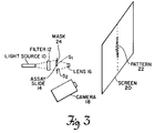
- Fig. 3 is a schematic diagram of a preferred embodiment of the invention.
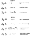
- Fig. 4 is a flow chart of the important steps in forming a colloidal gold-labeled antibody (Au-antibody) complex for use in the apparatus of the invention.
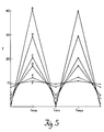
- Fig. 5 is a plot of the intensity of two adjacent maxima of double-slit interference pattern showing the change caused by varying the transmission through one slit.
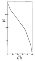
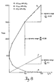
- Fig. 6 are plots of intensity I versus transmission T for changes in I max (curve ⁇ I max ) and changes in transmission (curve ⁇ T).
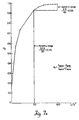
- Fig. 7(a) is a plot of the visibility V 2 of the fringe pattern as a function of the percent of transmission (I 2 %) through the second slit S 2 .
- Fig. 7(b) is a plot of the -log V 2 x 1,000 versus ⁇ % I 2 .
- Fig. 8 is a plot of the change in I max and I min as a function of change in transmission I 2 through slit S 2 .
- Fig. 9a-9d is a schematic flow diagram of an alternate embodiment of the invention.
- Fig. 10 is a schematic of yet another alternate embodiment.
- Fig. 11 is a schematic of an alternate embodiment in which the double-slit pattern is produced by a virtual slit S 2 and an actual slit S 1 and a mirror M.
- Fig. 12 is a schematic of a Fresnel's mirror embodiment of the invention.
- Fig. 13 is a schematic of a bi-prism embodiment of the invention.
- Fig. 14 is a schematic of a Billet's split lens embodiment of the invention.
- Fig. 15 is a schematic of a flow cell embodiment.
- Fig. 16 is a schematic of an alternate flow cell embodiment.
- Fig. 19 is a plot of the intensity of the principle maxima I o versus the number of slits.
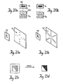
- Fig. 20(a)-20(b) is an alternate embodiment of a two or more slit embodiment in which the assay substrate is formed with slits.
- Fig. 21(a) is an alternate embodiment in which the slit opening is replaced by a square opening.
- Fig. 21(b) is an alternate embodiment of Fig. 20(a) wherein the slit opening is triangular in shape.
- Figs. 21(c) and (d) illustrate formation of an assay on a diagonal half of a square slit to form a triangular based diffraction pattern.
- FIG. 1 A diagram of the optical configuration used by Young is shown in Figure 1.
- a light source (S) is incident on two narrow, parallel slits (S 1 and S 2 ).
- Each slit has a width (D) which can be very small but remain larger than the wavelength of light.
- the slits are separated by a distance (a), which exceeds D.
- the light passing through the slits is diffracted and emerges as two wavefronts with identical wavelength and phase.
- the two wavefronts interfere and produce a visible interference pattern on the screen 20.
- the pattern consists of a series of bright and dark parallel bands which are typically referred to as fringes.
- the overall light amplitude at any given point in the interference pattern is the result of the superposition of the two wave amplitudes from S 1 and S 2 .
- the central fringe, located on the symmetry axis, is called the zero-order maximum.
- the minima are located exactly halfway between the maxima and are completely dark only when the two slits provide equal intensities.
- the assay method of the invention is based on a transduction mechanism of double-slit or multi-slit interference modulation.
- complete loss of transmission through only one slit in a double-slit interference configuration will produce a collapse of the fringe pattern to the single-slit diffraction band.
- a partial loss of transmission produces an intermediate pattern where the amplitudes of the interference maxima and minima are moving towards the condition of the diffraction band envelope. Therefore, any method of reducing the transparency of a slit can be related to a loss of fringe pattern.
- One way to convert this process to an assay method is to provide a complex which produces a localized coverage over one slit which is opaque enough to reduce the transmission of light through the slit.
- the reduction of light through the slit decreases the intensity of light available for interference with light emanating from the other slit, and thus decreases the formation of the resulting fringe pattern.
- the surface coverage due to the complex is equated with a predictable change of fringe pattern.
- the complex for producing loss of transmission through a slit can involve the temporary or permanent localization on the surface of the slit of any optically dense molecule or material which will cause a scattering or absorbance of the incident radiation from a source.
- Any physical phenomena that can alter or attenuate radiation transmission can affect the interference fringe formation. Therefore, any chemical phenomena producing one or more of these physical phenomena can potentially be detected by this technology.
- the physical phenomena may comprise a change in reflectance, absorbance, phase, refraction, or polarization of light impinging on an assay surface.
- Items capable of behaving thusly include colloidal gold-labeled molecules, colorimetric labels and pigments, bacteria, polymeric particles, cells, Langmuir-Blodgett films, as well as other polymeric films.
- An absorbance-modulated interference system may also be used to detect multiple analytes in a sample with a variable, incoherent source, such as a Xenon arc lamp and a scanning monochromater.
- a scanning spectrophotometer measures an absorbance spectrum as a function of the frequency of the incident radiation it may also be possible to measure the interference patterns produced by the transmissions at different frequencies. In this way, one could analyze a sample containing a variety of molecules with non-overlapping absorbance spectra; at a radiation wavelength coinciding with the absorbance maximum of a particular molecule in the sample the decrease of the interference pattern would be due to the attenuation resulting from the concentration of the molecule.
- FIG. 3 the apparatus for a first embodiment of the invention will be described in connection therewith.
- a light source 10 is disposed on a track (not shown) of an optical bench adjacent and in line with a foil mask 24 which is also mounted on the track.
- Mask 24 is formed with at least two narrow vertical slits S 1 and S 2 .
- An assay complex is formed on assay slide 14 which is positioned on mask 24 so as to cover slit S 1 .
- filter 12 is disposed on the track between source 10 and mask 24. If source 10 is a laser emitting highly intense monochromatic light, filter 12 may be a neutral density filter used to adjust the intensity of the light. If source 10 is a broad band moderately intense light source, filter 12 may be used to filter all but the desired wavelength for projection on the mask 24.
- a fringe pattern 22 which is magnified by lens 16 and projected onto screen 20.
- a second lens (not shown) may be disposed on the side of the mask nearest the source to increase the distribution of the pattern at the origin O.
- Camera 18 is used to photographically record the image of the pattern. This image may then be processed by converting the fringe patterns to intensity graphs using a densitometer and analyzing the intensity graphs produced with and without the slit covered by the assay slide to determine the concentration of the ligand in the sample.
- the double-slit mask component 24 is a critical item in this process and must be of high quality.
- the mask is cut out of foil by a laser process.
- Three different sizes have been experimented with as shown in Table 2 below. Those skilled in the art will appreciate that the dimensions indicated have been arbitrarily selected from a continuum of suitable values, and are exemplary rather than limiting on the invention.
- Foil #2 produces the most intense and distinct fringe patterns in the current format.
- the fringe separation (Y) for this foil when placed at X distance from a screen are determined from Eq. 1 and are listed in Table 3 below.
- the foil mask is secured on a magnetic mount (not shown) which is then placed on a magnetic strip attached to an X-Y-Z positioner in line with the light source 10.
- the assay method requires positioning of the assay slide over one slit and this must be done so that the slide edge remains between two slits and does not cause any diffraction of the light beam transmitting through the uncovered slit.
- the light source comprised a HeNe laser (Uniphase, 2mW), generating monochromatic light at 633 nm.
- Neutral density filters were used to reduce the laser intensity.
- the fringe patterns were recorded on film (Polaroid film #667, 3000ASA) and subsequently converted to intensity graphs by a video densitometer (PFGplus 640-3-U-RT PCVision Plus Frame Grabber with a 640x480 Display, OPTIMAS - Optical Measurement & Analysis Software, PVM-1342Q Sony Trinatron 13" color monitor with multiple inputs, Logimouse Plus - Logitech Mechanical Mouse, SYS/386-80-color-1 IBM Compatible 386 20 Mhz with EGA Color Monitor and 80 Megabyte Hard Drive) using a video camera (815-2000-0000 Cohu Series 4800 High Resolution CCD Monochrome Camera) focused on the illuminated photographs. To make a tracing the cursor was positioned at the top of a fringe pattern or diffraction envelope with the single-slit, and then drawn through the center of the pattern and terminated at the opposing side.
- a video densitometer PGplus 640-3-U-RT PCVision Plus Frame Grabber with a 640
- FIGs. 4a-g A flow chart of a first embodiment of the assay chemistry of the invention followed by the optical test is summarized in Figs. 4a-g.
- the ligand is rabbit IgG which is incubated with a coverslip 14 (Fig. 4a) coated with anti-rabbit IgG, followed by incubation with a colloidal gold-labeled anti-ligand, such as, goat anti-rabbit IgG 40 (Fig. 4b).
- a silver enhancement step wherein the gold colloid nucleates precipitation of silver from a solution 42 as it comes into contact with the labeled antibody (Fig. 4c)
- the coverslip exhibits a deposition of darkly stained antibody-antigen complex.
- Insertion of this treated assay coverslip over one slit S 2 of a double-slit configuration produces loss of transparency through slit S 2 (Fig. 4d) resulting in loss of intensity I 2 of light from S 2 (Fig. 4e) and an observable, measurable loss of interference fringes (Fig. 4f). This loss in amplitude of fringes is then related to analyte concentration (Fig. 4g) in the quantification procedure described later in Section E.
- the objective of the immobilization chemistry is covalent attachment of the anti-ligand, in this case a protein, which will selectively bind the target ligand or analyte.
- the coverslip is acid treated to produce reactive silanol groups:
- a 2% solution (v/v) of APTES was prepared by mixing 200 ul of APTES in 9.8 ml toluene (dried over molecular sieves). The coverslips were soaked for 2 h, and rinsed in dry toluene. (see Weetal, H.H., "Methods of Enzymology", Mosach, K., Ed., Academic Press: New York, 1976, Vol. XLIV, pp 139).
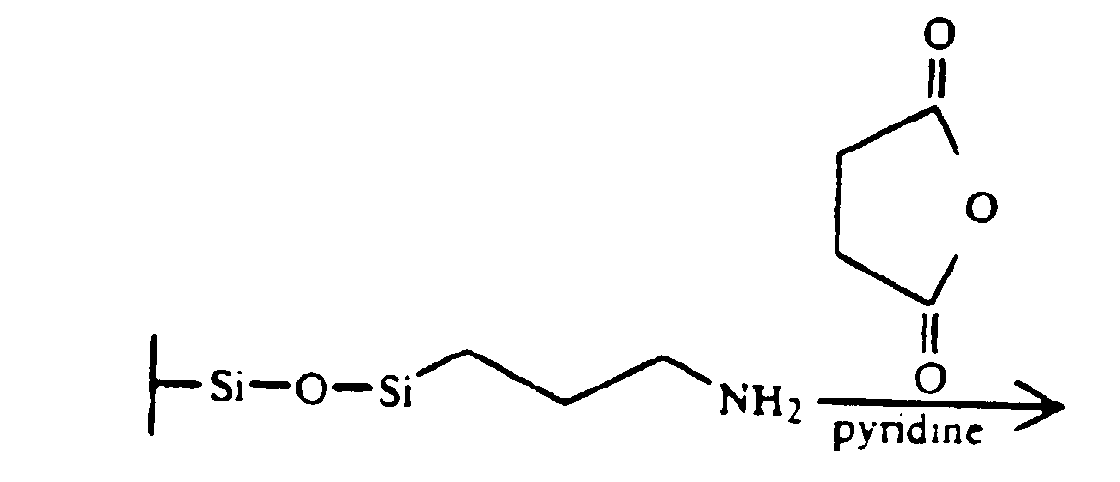
- the next step is the reaction of the amine derivatized glass with succinic anhydride to produce a carboxylic acid group on the surface:
- a solution of 0.20 g (2 mmol) succinic anhydride was combined with 40 mg (0.33 mmol) 4-dimethylaminopyridine in 6 ml anhydrous pyridine and divided into test tubes.
- the amine-derivatized glass coverslips were placed into the tubes, which were then sealed and shaken at room temperature for 16-20 hours. Coverslips were removed, rinsed with pyridine, methylene chloride and ether. If stored, they were placed in a desiccator over P 2 O 5 .
- a 0.6 ml phosphate buffer was placed in test tubes with prepared coverslips.
- a 2% solution of carbodiimide solution was prepared by mixing 75.0 mg EDC with 3.75 ml phosphate buffer.
- 0.6 ml EDC solution was added, dropwise, to each of the test tubes containing the coverslips, and capped tightly.
- the solutions were shaken for 3.5 - 4 hours at room temperature.
- the coverslips were then removed and shaken in borate buffer (Bottle #4) for 5 min. followed by two more rinsings with borate buffer.
- the activated surface is then reacted with the alkylamine functional groups of the protein (anti-rabbit IgG) to be immobilized, forming an amide linkage:
- a 0.05 mg/ml solution of anti-rabbit IgG was prepared by adding 73 ul of anti-rabbit IgG (4.1 mg/ml; commercially available from Sigma) to 6 ml borate buffer, which was then aliquotted into 6 test tubes.
- the coverslips were immersed, the test tubes were sealed and rocked gently overnight. The coverslips were removed and the supernatant was retained for absorbance measurements.
- the covers lips were then added to test tubes containing 1 ml 0.1 M ethanolamine (Bottle #5) and gently mixed for 30 min.
- the coverslips were then transferred to 1 ml of BSA solution (Bottle #6) and gently mixed for 30 min.
- the coverslips were then rinsed in PBS and stored in storage buffer (Bottle #7) or PBS, 4 - 6 degrees C.
- the protein used as the anti-ligand can also be immobilized to a transparent plastic substrate that has been coated with a polymer containing residual carboxylate groups (Sera-Coat, Seradyn) for carbodiimide coupling.
- a polymer containing residual carboxylate groups Sera-Coat, Seradyn
- rabbit IgG was incubated with the anti-rabbit IgG coverslips, rinsed with PBS, and then treated with gold-labeled anti-rabbit IgG, and the silver enhancement step.
- coverslip were rinsed with PBS two times.
- a coverslip was positioned in the outer groove of a disposable cuvette and 20-40 ul of colloidal gold(30nm)-labeled Goat anti-rabbit IgG (AuroProbe EM GAR G30, Amersham) was pipetted onto the surface and left for 60 min.
- the coverslip was then placed inside the same cuvette and rinsed thoroughly three times with PBS followed by three rinses with H 2 O.
- a silver enhancement step follows which produces a more dramatic decrease in the transparency of the reacted assay substrate.
- the gold nucleates precipitation of silver from a solution in the region of the labeled antibody:
- Equations have been derived for describing the dependency of the interference fringes on the luminescence intensities produced by the slits, and those equations can be employed in this detection method for quantifying the results of an assay.
- 1 is a coherency limit for a laser source.
- Table 4 contains values for a model system where the intensity (I 1 and I 2 ) through each slit are assigned a value of 10.
- the intensity is identical through each slit the upper value of 1.0 exists for V 2 ; as the intensity, I 2 , is decreased the V 2 decreases towards 0.0.
- V 2 1.0
- the fringe pattern has the maximum amplitude of I max and a complete loss of amplitude at I min .
- V 2 moves towards 0.0 the fringe pattern collapses to the diffraction envelope.
- a graph of two adjacent fringes is shown in Figure 5.
- the line labeled A describes the intensities of I max and I min formed by two equal, unobstructed slits.
- the lines B through F show the change in amplitudes as the intensity through one slit is decreased. At the I max for line F the intensity amplitude is almost 10, which is the intensity of light passing through the unobstructed slit, or I 1 .
- the existing formulas which govern absorbance spectroscopy can be linked with the formulas used for evaluating interference phenomena since both methodologies are based on transmission intensity of a source and the resultant intensity due to passing the radiation through a sample.
- I 2 transmission intensity
- the ⁇ I max function would be more than 2 times as sensitive as the ⁇ T function.
- the increased dynamic range results form the fact that Eq. 13 contains two terms which change as a function of absorbance modulation. Since sensitivity of spectroscopic analysis is defined by the magnitude of absorptivity as well as the minimum absorbance which can be measured with the required degree of certainty, the ⁇ I max function would provide greater spectrophotometric sensitivity.
- the V 2 (Eq. 3) is plotted in Figure 7(a) as a function of the percent of transmission (I 2 %) through the second slit (S 2 ) (Table 4). At 100% transmission, equal intensities pass through two identical slits and the fringe pattern has the most defined fringes, where I max is at its highest value and I min is zero. At 0% complete loss of the fringe pattern occurs and only the diffraction envelope remains. On the graph shown in Figure 7(a) one can arbitrarily assign 40 units on the visibility scale. In the assay method, the change in transmission through S 2 is a function of the concentration of analyte bound to the coverslip, and therefore the I 2 % is the concentration component.
- Dynamic range ⁇ V 2 ⁇ I 2 %
- a loss of 50% transmission in I 2 produces a visibility change from 1.0 to 0.94, or 2.5 units of signal.
- a loss of transmission in I 2 from 50% to 0% produces a visibility change from 0.94 to 0.0, or 37.5 units of signal, and an increase of dynamic range to 0.75.
- a more linear plot of the Visibility (V 2 ) data can be generated by plotting -logV 2 x 1000 against ⁇ %I 2 , which is shown in Figure 7(b).
- the change in fringe visibility is not the only useful function for calculating a dynamic response.
- the slit format in principle, is more sensitive than straight optical density. This enhanced sensitivity can be appreciated by comparing the relative resolutions of the measurements.
- Resolution is conventionally taken as the inverse of the dynamic range. For a dynamic range of 0.10, as calculated for the linear loss of transmission, the resolution, or number that can be measured with certainty, would be 10.00. For a dynamic range of 0.22, as calculated for the change in I max from 100 to 50% loss of transmission, the resolution would be 4.54, meaning that the certainty of the measured value would be to a smaller number than the preceding case, and thus more accurate.
- a dynamic range of 0.75 has a resolution of 1.33, providing even more accuracy.
- the sensitivity of this assay method is defined by the number of target molecules required to obstruct the transmission through S 2 to produce a measurable change in the fringe pattern. Several factors will contribute to the ultimate sensitivity:
- the detection method of the invention possesses a number of substantial advantages.
- the signal output is in the form of both an amplitude parameter and a pattern formation which offers greater information content for data analysis over a system based only on intensity measurement.
- the signal in the form of the entire interference pattern, may be stored in computer memory and compared with a computer standard so that a microscopic alteration to the standard pattern, detectable only through computerized treatment, could deliver an extraordinarly sensitive diagnostic.
- Another advantage of the transduction method of the invention is that the amplitude component in the form of I max has been increased fourfold over a direct measurement of intensity, due to the contribution of the two individual wavefronts as well as the constructively interfering electromagnetic waves. Again, this increases the information content of the potential signal which should increase the dynamic range and thus the sensitivity of the method. A sensitivity of less than 10 5 molecules is possible which would equal or exceed the sensitivity of isotopic methods.
- a compact bench top instrument should be easily manufacturable, with the assay chemistry incorporated into a disposable dipstick.
- the dipstick would require incubations with sample, gold-labeled antibody, and silver enhancement solutions, which could be accomplished in 1 - 2 hours.
- simple incubation with the sample, followed by rinsing would complete the procedure. (It may be possible that as few as 2 - 3 bound cells would suffice to alter the fringe pattern).
- the slit number and shape may be varied.
- the present preferred embodiment is a double-slit formed of two identical, parallel slits, but predictable interference phenomena can be produced by other numbers of identical slits. With more than two slits it would be possible to assign individual assays to a different slit or test assays in each slit would be for multiple analytes with a single procedure.
- holes may be used in place of slits to form a circular interference pattern.
- two pinholes will also produce interference fringes and can be precision made to about 2 ⁇ m in diameter, which would give a smaller total surface area than the proposed slits (and thus enhance sensitivity).
- the assay chemistry could be performed as drops on the pinhole, therefore using very minute sample volumes.
- the assay complex occurring on the glass coverslip 50 could also serve to produce two slits S 1 and S 2 from a single slit S 0 as shown in Fig. 9a-9d.
- the anti-ligand S 2 is immobilized on an edge of the coverslip (Fig. 9(b)).
- the complex would darken the edge of the coverslip, Fig. 9(c), which would then be positioned over the single slit S 0 Fig. 9(a) as shown in Fig. 9(d) forming two slits S 1 and S 2 .
- the assay chemistry could be centralized on a glass slit 90 so that gold-labeled antibody complex forms a double slit 92 as shown in Fig. 10.
- light rays from a single slit S 1 pass to the screen 80 via two paths, one of which is direct, A-A, and the other of which is an indirect path, B-B, created by reflection from a mirror M placed in the center line C/L so as to produce a reflection which would appear to emanate from a slit S 2 located equidistant from center line C/L.
- the source is therefore viewed by two paths, one direct and one reflected at a glancing angle in a mirror. The reflection reverses the phase 180°, but otherwise the analysis and the fringes are the same.
- the area of reflection on the mirror would be the location of the assay complex, which would cause appearance or loss of reflection.
- a Fresnel's mirror can be used as in Fig. 12 to produce two virtual slits which are formed with a point source S projected on two plane mirrors, M 1 and M 2 , mutually inclined at a small angle.
- S 1 and S 2 act as coherent sources.
- the prisms thus form two virtual slit images, S 1 and S 2 .
- a so-called Billet's split lens arrangement formed by two convex lens can form two images, both of which are real as shown in Fig. 14.
- interference fringes are formed in the region defined by the diverging cones from the sources S 1 and S 2 .
- Assay formats could be developed which altered the optical arrangement, thus altering fringe patterns.
- application to the Lloyd's mirror (Fig. 11) or Fresnel's mirror (Fig. 12) configurations would require location of the assay complex in the region of reflection on the mirror, which produces the virtual slit. If the assay chemistry resulted in a loss of reflectivity of the mirror's surface the intensity of reflected light would decrease and the interference pattern would be modulated.
- Application to the Fresnel bi-prism (Fig. 13) or Billet's split lens (Fig. 14) would require location of the assay complex on one of the prisms or lenses so that the intensity of diffracted radiation after formation of the assay complex would no longer equal the intensity diffracted by the other optical unit in the pair.
- reactions could be monitored by use of a transport flow-cell microcell 94 which would build up an interfering absorbance on screen 96.
- B is a reference cuvette
- A is an assay cuvette
- C the cuvette separation
- Another configuration would have slits S 1 and S 2 incorporated into a transport flow cell 86 as in Fig. 16.
- the cell 86 is disposed opposite a Source 85.
- Antiligand would be immobilized on S 1 and buildup of ligand on its surface would alter the fringe pattern as seen by the detector 87.
- the dynamic range of the detection system may be enhanced not only by increasing the number of slits, but by increasing the number of slits covered by the assay.
- Table 6 shows how the intensity of the principle maxima increases as a function of N 2 times the intensity I o of one slit.
- I I o 10 1 I o 10 2 4I o 40 3 9I o 90 4 16I o 160 5 25I o 250 6 36I o 360 7 49I o 490
- Fig. 19 is a plot of the data from Table 6. As shown in Fig.
- the assay substrate 60 could also contain the slits S 1 and S 2 (Fig. 20(a)) with the anti-ligand 62 immobilized to one of the slits (i.e. S 1 ).
- the assay reaction causes slit S 1 to become less transparent (Fig. 20b).
- the optical radiation is passed through identical slit material, preserving the symmetrical phases of the two wavefronts. Also, any nonspecific binding of protein from the sample would occur equally in the regions of S 1 and S 2 , again preserving the symmetry of I 1 and I 2 since both intensities would be identically altered by the contaminating material.
- Fig. 21(a) and 21(b) illustrates alternate embodiments in which the mask or assay slit 70/70' is square shaped (Fig. 21a) or triangular (Fig. 21(b)) in shape.
- a single square slit will produce an interference pattern 72 as shown in Fig. 21(a).
- a single triangular shaped slit 70' produces the pattern 72' of Fig. 21(b).
- the square slit 70 becomes a triangular slit Fig. 21(d), and a triangular based diffraction pattern 72' occurs Fig. 21(b).
- a detector (not shown) monitors the appearance of the new diffraction pattern 72' to determine the presence and concentration of the ligand.
Landscapes
- Health & Medical Sciences (AREA)
- Life Sciences & Earth Sciences (AREA)
- Immunology (AREA)
- Engineering & Computer Science (AREA)
- Chemical & Material Sciences (AREA)
- Molecular Biology (AREA)
- Biomedical Technology (AREA)
- Hematology (AREA)
- Urology & Nephrology (AREA)
- Analytical Chemistry (AREA)
- Physics & Mathematics (AREA)
- Biochemistry (AREA)
- General Health & Medical Sciences (AREA)
- General Physics & Mathematics (AREA)
- Pathology (AREA)
- Microbiology (AREA)
- Cell Biology (AREA)
- Food Science & Technology (AREA)
- Medicinal Chemistry (AREA)
- Biotechnology (AREA)
- Investigating Or Analysing Materials By The Use Of Chemical Reactions (AREA)
- Investigating Or Analysing Materials By Optical Means (AREA)
Description
| COLORS OF COMPOUNDS, SPECTRAL COLORS AND WAVELENGTHS | ||
| Color of Compound | Spectral color absorbed | Approx. wavelength (nm) |
| Colorless | Ultraviolet | <400 |
| Lemon Yellow | Violet | 410 |
| Yellow | Indigo | 430 |
| Orange | Blue | 480 |
| Red | Blue-green | 500 |
| Purple | Green | 530 |
| Violet | Lemon yellow | 560 |
| Indigo | Yellow | 580 |
| Blue | Orange | 610 |
| Blue-green | Red | 680 |
| Green | Purple-red | 720 |
| Colorless | Infrared | >720 |
| DIMENSIONS OF AIR SLITS | |||
| Foil # | Slit width (µm) | Slit separ. (µm) | Slit length (mm) |
| 1 | 100 | 500 | 10 |
| 2 | 50 | 500 | 2 |
| 3 | 50 | 1000 | 2 |
| CALCULATED FRINGE SEPARATIONS FOR FOIL #2 AT VARYING DISTANCES BETWEEN SLITS AND SCREEN | |||
| X (cm) | a (µm) | λ (µm) | Y (µm) |
| 50 | 550 | 0.633 | 575.4 |
| 40 | 550 | 0.633 | 460.4 |
| 30 | 550 | 0.633 | 345.2 |
| 20 | 550 | 0.633 | 230.2 |
| 10 | 550 | 0.633 | 115.1 |
| 5 | 550 | 0.633 | 57.5 |




| THE CHANGES IN IMAX AND IMIN WITH LOSS OF TRANSMISSION THROUGH ONE SLIT | |||||
| I1 | I2 | Imax | Imin | | Graph |
| 10 | 10 | 40.0 | 0 | 1.0 | A |
| 10 | 9.5 | 38.99 | 0.006 | 0.999 | |
| 10 | 9.0 | 37.97 | 0.026 | 0.998 | |
| 10 | 8.0 | 35.88 | 0.111 | 0.993 | |
| 10 | 7.0 | 33.73 | 0.266 | 0.984 | |
| 10 | 6.0 | 31.49 | 0.508 | 0.968 | |
| 10 | 5.0 | 29.14 | 0.86 | 0.94 | B |
| 10 | 2.0 | 20.94 | 3.05 | 0.74 | C |
| 10 | 1.0 | 17.32 | 4.68 | 0.57 | D |
| 10 | 0.1 | 12.10 | 8.10 | 0.19 | E |
| 10 | 0.01 | 1.64 | 9.38 | 0.063 | F |
| IMAX VALUES CALCULATED FROM AN ABSORBANCE SERIES | ||||
| εbc | T = 10-εbc | | I0 | Imax |
| .01 | 0.977 | 1.976 | 1.0 | 3.95 |
| .1 | 0.794 | 1.782 | 1.0 | 3.57 |
| .2 | 0.630 | 1.587 | 1.0 | 3.21 |
| .3 | 0.501 | 1.415 | 1.0 | 2.91 |
| .4 | 0.398 | 1.261 | 1.0 | 2.66 |
| .5 | 0.316 | 1.124 | 1.0 | 2.44 |
| 1.0 | 0.100 | 0.632 | 1.0 | 1.73 |
| 1.5 | 0.031 | 0.352 | 1.0 | 1.38 |
| 2.0 | 0.010 | 0.200 | 1.0 | 1.21 |
| Coverslip | Optical Fiber | |
| Area | 968 mm2 | 74 mm2 |
| Antibody immobilized | 638±134ng | 71±3ng |
| (0.66 ng/mm2, 4 fmol/mm2) | (0.96 ng/mm2, 6 fmol/mm2) | |
| Specific antigen | 350±50 ng | 27±4ng |
| binding | (0.36 ng/mm2) | (0.36 ng/mm2) |
Antigen capture (50%) = 0.001 fmol
= 6 X 10⁵ molecules
Labeled antibody capture (50%) = 0.0005 fmol
= 3 X 10⁵ molecules
| INTENSITY OF PRINCIPAL MAXIMA FROM N SLITS IS N2 X Io | ||
| # Slits | I | Io = 10 |
| 1 | Io | 10 |
| 2 | 4Io | 40 |
| 3 | 9Io | 90 |
| 4 | 16Io | 160 |
| 5 | 25Io | 250 |
| 6 | 36Io | 360 |
| 7 | 49Io | 490 |

Claims (22)
- A method of optical detection of the presence of a ligand in a sample in which the ligand is attached to an assay substrate and reacted with an antiligand to form a complex of the ligand and the antiligand on the assay substrate, the optical characteristics of which complex are distinct from those of the ligand, comprising the steps of:a) forming an interference pattern by projecting light through openings in a mask disposed in the path of the light so that the diffracted beams emerging from the openings interfere with one another to create said pattern;b) disturbing at least one, but not all, such diffracted beams with the complex, which is positioned in the path of at least one, but not all, such diffracted beams thereby changing the interference pattern; andc) observing the change in the pattern to determine the presence of the ligand.
- The method of claim 1 wherein the change in the interference pattern results from a phenomenon selected from scattering, absorbance, phase change, refraction or polarization of the incident light, and/or wherein the change in the pattern is dependent on the concentration of the ligand in the assay and the method includes the step of correlating the change to determine such concentration.
- A method for providing an optical indication of the relative concentration of a ligand and an antiligand, e.g. a metal-labeled antiligand, in a sample comprising the following steps:and optionally the points in step (c) are substantially all points within a range of points within the interference pattern.a) forming an interference pattern by projecting light through a mask having N slits wherein N is an integer greater than one;b) covering N-X slits with a complex attached to an assay substrate, wherein the complex includes said ligand and said antiligand, wherein the complex results in change in an optical characteristic of the covered slits and a resultant change in the interference pattern, and wherein X is an integer less than N; andc) determining the concentration by measuring the change in the optical characteristic of one or more points on the interference pattern before and after the N-X slits are covered;
- The method of claim 3 wherein either the ligand or antiligand is an optically dense molecule which causes a scattering, absorbance, phase change, refraction or polarization change of incident light.
- The method of claim 3 wherein N = 6 and X = 5, or N = 2 and X = 1.
- The method of claim 3 wherein the concentration is measured by determining a visibility parameter and comparing the determined visibility to a reference curve of visibility versus concentration.
- A method of providing an optical indication of the presence of a ligand or an antiligand in a sample comprising the following steps:a) forming an interference pattern by projecting light through a mask having N slits wherein N is an integer greater than one,b) covering N - X slits with the sample, where the sample includes said ligand and said antiligand, where the sample is disposed on an assay substrate, and where X is an integer less than N; andc) reacting the ligand and antiligand to produce a loss in transparency through the N - X covered slits indicating the presence of the ligand or antiligand.
- A method of determining the concentration of a ligand in a sample comprising the steps of:a) generating an interference pattern between two or more electromagnetic waves, e.g. light waves, said waves resulting from the passage of a beam of electromagnetic energy through a mask containing openings transparent to the electromagnetic energy;b) immobilizing the ligand on an assay substrate;c) reacting the ligand with an antiligand to cause a change in the response of the ligand to the waves;d) modulating the interference pattern by disposing the immobilized and reacted ligand in the path of at least one, but not all, of the waves; ande) determining the ligand concentration by the change in the interference pattern, e.g. using a densitometer.
- The method of claim 8 wherein the change in the interference pattern is a change resulting from scattering, absorbance, polarization or refraction.
- The method of claim 8 wherein the interference results from passing the waves through N slits formed in a mask wherein N is an integer greater than one.
- The method of claim 10 wherein the slits are square shaped or triangular shaped.
- The method of claim 10 wherein the mask is formed on the assay substrate on which the ligand and antiligand react.
- The method of claim 12 wherein X slits are covered by the assay, where X is an integer less than N.
- The method of claim 8 wherein the change in the interference pattern is determined by calculating the visibility parameter of the pattern and the concentration of the ligand is determined by comparing the visibility parameter with a reference curve of visibility versus ligand concentration.
- The method of claim 8 wherein one or more of the slits is a virtual slit which e.g. is/are produced by a device from the class comprising a Lloyd's mirror, a Fresnel's mirror, a Fresnel biprism, or a Billet's split lens.
- The method of claim 10 wherein the slits are transparent regions in an otherwise substantially opaque surface of a flow cell, and wherein the antiligand is immobilized on at least one, but not all of the slits.
- Apparatus for detecting the presence or concentration of a ligand on a substrate comprising:a) a light source such as a laser for emitting a beam of light:b) a beam splitter comprising a mask having at least two openings for causing the beam of light to split into at least two split beams, which split beams interfere with one another to form an interference pattern;c) the substrate;d) at least one ligand disposed on the substrate and positioned in the path of at least one of the split beams, wherein the ligand is for modulating one of the split beams to change the interference pattern in a manner related to the concentration of ligand on the substrate; ande) detecting means such as an optoelectronic detector for quantifying the pattern change produced by the ligand(s) and determining therefore the concentration of ligand.
- Apparatus for determining the concentration of a ligand in a fluid by an assay methodology, e.g. an immunoassay comprising:a) an interferometer for generating an interference pattern, said interferometer comprising a mask with two or more openings, whereby waves such as light waves passing through said openings are diffracted to produce an interference pattern;b) at least one ligand from the fluid disposed on a substrate in the path of one of the waves so as to modulate the interference pattern;c) an antiligand, which when reacted with the ligand, causes a ligand-concentration-dependent change in the interference pattern; andd) detector means for detecting changes in the interference pattern caused by the modulations and correlating the detected changes with ligand concentration.
- The apparatus of claim 18, wherein the modulation results from scattering, absorbance, polarization or refraction of the light waves.
- The apparatus of claim 18 wherein the openings are formed on the assay substrate on which the ligand and antiligand react.
- The apparatus of claim 18 wherein the ligand is taken from the group comprising: molecules, bacteria, polymeric particles, cells and films.
- The apparatus of claim 18 wherein the ligand absorbs light in a predetermined frequency range and the apparatus further includes a light source that generates a beam of light waves within that range.
Applications Claiming Priority (2)
| Application Number | Priority Date | Filing Date | Title |
|---|---|---|---|
| US07/706,772 US5196350A (en) | 1991-05-29 | 1991-05-29 | Ligand assay using interference modulation |
| PCT/US1992/010072 WO1994012882A1 (en) | 1991-05-29 | 1992-11-24 | Ligand assay using interference modulation |
Publications (3)
| Publication Number | Publication Date |
|---|---|
| EP0670043A1 EP0670043A1 (en) | 1995-09-06 |
| EP0670043A4 EP0670043A4 (en) | 1996-10-09 |
| EP0670043B1 true EP0670043B1 (en) | 1999-01-27 |
Family
ID=26785190
Family Applications (1)
| Application Number | Title | Priority Date | Filing Date |
|---|---|---|---|
| EP92925374A Expired - Lifetime EP0670043B1 (en) | 1991-05-29 | 1992-11-24 | Ligand assay using interference modulation |
Country Status (4)
| Country | Link |
|---|---|
| US (1) | US5196350A (en) |
| EP (1) | EP0670043B1 (en) |
| DE (1) | DE69228325T2 (en) |
| WO (1) | WO1994012882A1 (en) |
Families Citing this family (102)
| Publication number | Priority date | Publication date | Assignee | Title |
|---|---|---|---|---|
| GB2273772A (en) * | 1992-12-16 | 1994-06-29 | Granta Lab Ltd | Detection of macromolecules utilising light diffraction |
| US5413939A (en) * | 1993-06-29 | 1995-05-09 | First Medical, Inc. | Solid-phase binding assay system for interferometrically measuring analytes bound to an active receptor |
| US5638459A (en) * | 1994-09-20 | 1997-06-10 | Neopath, Inc. | Method and apparatus for detecting a microscope slide coverslip |
| US5715327A (en) * | 1994-09-20 | 1998-02-03 | Neopath, Inc. | Method and apparatus for detection of unsuitable conditions for automated cytology scoring |
| US5679579A (en) * | 1996-01-29 | 1997-10-21 | First Medical, Inc. | Immunofluorescence measurement of analytes bound to a substrate and apparatus therefor |
| US6582921B2 (en) * | 1996-07-29 | 2003-06-24 | Nanosphere, Inc. | Nanoparticles having oligonucleotides attached thereto and uses thereof |
| US5922550A (en) * | 1996-12-18 | 1999-07-13 | Kimberly-Clark Worldwide, Inc. | Biosensing devices which produce diffraction images |
| US5958704A (en) | 1997-03-12 | 1999-09-28 | Ddx, Inc. | Sensing system for specific substance and molecule detection |
| US6060256A (en) * | 1997-12-16 | 2000-05-09 | Kimberly-Clark Worldwide, Inc. | Optical diffraction biosensor |
| US6221579B1 (en) | 1998-12-11 | 2001-04-24 | Kimberly-Clark Worldwide, Inc. | Patterned binding of functionalized microspheres for optical diffraction-based biosensors |
| US6579673B2 (en) | 1998-12-17 | 2003-06-17 | Kimberly-Clark Worldwide, Inc. | Patterned deposition of antibody binding protein for optical diffraction-based biosensors |
| US20030096321A1 (en) * | 1999-05-19 | 2003-05-22 | Jose Remacle | Method for the identification and/or the quantification of a target compound obtained from a biological sample upon chips |
| US7167615B1 (en) | 1999-11-05 | 2007-01-23 | Board Of Regents, The University Of Texas System | Resonant waveguide-grating filters and sensors and methods for making and using same |
| US6399295B1 (en) | 1999-12-17 | 2002-06-04 | Kimberly-Clark Worldwide, Inc. | Use of wicking agent to eliminate wash steps for optical diffraction-based biosensors |
| WO2001071322A2 (en) * | 2000-03-22 | 2001-09-27 | Goh M Cynthia | Method and apparatus for multiple-analyte assay |
| JP4554205B2 (en) * | 2001-09-13 | 2010-09-29 | アクセラ インコーポレーテッド | Method and apparatus for calibration based on diffraction of light |
| US7098041B2 (en) * | 2001-12-11 | 2006-08-29 | Kimberly-Clark Worldwide, Inc. | Methods to view and analyze the results from diffraction-based diagnostics |
| US7102752B2 (en) * | 2001-12-11 | 2006-09-05 | Kimberly-Clark Worldwide, Inc. | Systems to view and analyze the results from diffraction-based diagnostics |
| US7384598B2 (en) * | 2001-12-21 | 2008-06-10 | Kimberly-Clark Worldwide, Inc. | Diagnostic device |
| US7244393B2 (en) * | 2001-12-21 | 2007-07-17 | Kimberly-Clark Worldwide, Inc. | Diagnostic device and system |
| US8367013B2 (en) * | 2001-12-24 | 2013-02-05 | Kimberly-Clark Worldwide, Inc. | Reading device, method, and system for conducting lateral flow assays |
| US20030119203A1 (en) * | 2001-12-24 | 2003-06-26 | Kimberly-Clark Worldwide, Inc. | Lateral flow assay devices and methods for conducting assays |
| US7771922B2 (en) * | 2002-05-03 | 2010-08-10 | Kimberly-Clark Worldwide, Inc. | Biomolecule diagnostic device |
| US7223368B2 (en) * | 2002-05-03 | 2007-05-29 | Kimberly-Clark Worldwide, Inc. | Diffraction-based diagnostic devices |
| US7118855B2 (en) * | 2002-05-03 | 2006-10-10 | Kimberly-Clark Worldwide, Inc. | Diffraction-based diagnostic devices |
| US7223534B2 (en) * | 2002-05-03 | 2007-05-29 | Kimberly-Clark Worldwide, Inc. | Diffraction-based diagnostic devices |
| US7485453B2 (en) * | 2002-05-03 | 2009-02-03 | Kimberly-Clark Worldwide, Inc. | Diffraction-based diagnostic devices |
| US7214530B2 (en) * | 2002-05-03 | 2007-05-08 | Kimberly-Clark Worldwide, Inc. | Biomolecule diagnostic devices and method for producing biomolecule diagnostic devices |
| US7091049B2 (en) * | 2002-06-26 | 2006-08-15 | Kimberly-Clark Worldwide, Inc. | Enhanced diffraction-based biosensor devices |
| EP1535241A1 (en) * | 2002-08-20 | 2005-06-01 | Cyvera Corporation | Diffraction grating-based optical identification element |
| US7901630B2 (en) * | 2002-08-20 | 2011-03-08 | Illumina, Inc. | Diffraction grating-based encoded microparticle assay stick |
| US7900836B2 (en) * | 2002-08-20 | 2011-03-08 | Illumina, Inc. | Optical reader system for substrates having an optically readable code |
| US7923260B2 (en) | 2002-08-20 | 2011-04-12 | Illumina, Inc. | Method of reading encoded particles |
| US7872804B2 (en) * | 2002-08-20 | 2011-01-18 | Illumina, Inc. | Encoded particle having a grating with variations in the refractive index |
| US7164533B2 (en) * | 2003-01-22 | 2007-01-16 | Cyvera Corporation | Hybrid random bead/chip based microarray |
| US7441703B2 (en) * | 2002-08-20 | 2008-10-28 | Illumina, Inc. | Optical reader for diffraction grating-based encoded optical identification elements |
| WO2004019277A1 (en) * | 2002-08-20 | 2004-03-04 | Cyvera Corporation | Diffraction grating-based encoded micro-particles for multiplexed experiments |
| US7619819B2 (en) | 2002-08-20 | 2009-11-17 | Illumina, Inc. | Method and apparatus for drug product tracking using encoded optical identification elements |
| US20050227252A1 (en) * | 2002-08-20 | 2005-10-13 | Moon John A | Diffraction grating-based encoded articles for multiplexed experiments |
| US7508608B2 (en) * | 2004-11-17 | 2009-03-24 | Illumina, Inc. | Lithographically fabricated holographic optical identification element |
| US7432105B2 (en) * | 2002-08-27 | 2008-10-07 | Kimberly-Clark Worldwide, Inc. | Self-calibration system for a magnetic binding assay |
| US7285424B2 (en) * | 2002-08-27 | 2007-10-23 | Kimberly-Clark Worldwide, Inc. | Membrane-based assay devices |
| US7314763B2 (en) * | 2002-08-27 | 2008-01-01 | Kimberly-Clark Worldwide, Inc. | Fluidics-based assay devices |
| EP1552475A1 (en) * | 2002-09-12 | 2005-07-13 | Cyvera Corporation | Chemical synthesis using diffraction grating-based encoded optical elements |
| WO2004025560A1 (en) * | 2002-09-12 | 2004-03-25 | Cyvera Corporation | Assay stick comprising coded microbeads |
| AU2003270726A1 (en) * | 2002-09-12 | 2004-04-30 | Cidra Corporation | Diffraction grating-based encoded micro-particles for multiplexed experiments |
| US7092160B2 (en) * | 2002-09-12 | 2006-08-15 | Illumina, Inc. | Method of manufacturing of diffraction grating-based optical identification element |
| CA2499037A1 (en) * | 2002-09-12 | 2004-03-25 | Cyvera Corporation | Method and apparatus for labelling using diffraction grating-based encoded optical identification elements |
| EP1575707A1 (en) * | 2002-09-12 | 2005-09-21 | Cyvera Corporation | Method and apparatus for aligning elongated microbeads in order to interrogate the same |
| US20100255603A9 (en) | 2002-09-12 | 2010-10-07 | Putnam Martin A | Method and apparatus for aligning microbeads in order to interrogate the same |
| US7169550B2 (en) * | 2002-09-26 | 2007-01-30 | Kimberly-Clark Worldwide, Inc. | Diffraction-based diagnostic devices |
| US7781172B2 (en) * | 2003-11-21 | 2010-08-24 | Kimberly-Clark Worldwide, Inc. | Method for extending the dynamic detection range of assay devices |
| US20040106190A1 (en) * | 2002-12-03 | 2004-06-03 | Kimberly-Clark Worldwide, Inc. | Flow-through assay devices |
| US20040121334A1 (en) * | 2002-12-19 | 2004-06-24 | Kimberly-Clark Worldwide, Inc. | Self-calibrated flow-through assay devices |
| US7247500B2 (en) | 2002-12-19 | 2007-07-24 | Kimberly-Clark Worldwide, Inc. | Reduction of the hook effect in membrane-based assay devices |
| US8081792B2 (en) * | 2003-08-20 | 2011-12-20 | Illumina, Inc. | Fourier scattering methods for encoding microbeads and methods and apparatus for reading the same |
| US7027163B2 (en) * | 2003-01-24 | 2006-04-11 | General Dynamics Advanced Information Systems, Inc. | Grating sensor |
| US7445938B2 (en) * | 2003-01-24 | 2008-11-04 | General Dynamics Advanced Information Systems, Inc. | System and method for detecting presence of analytes using gratings |
| US7851209B2 (en) * | 2003-04-03 | 2010-12-14 | Kimberly-Clark Worldwide, Inc. | Reduction of the hook effect in assay devices |
| US20040197819A1 (en) * | 2003-04-03 | 2004-10-07 | Kimberly-Clark Worldwide, Inc. | Assay devices that utilize hollow particles |
| US20060057729A1 (en) * | 2003-09-12 | 2006-03-16 | Illumina, Inc. | Diffraction grating-based encoded element having a substance disposed thereon |
| US7713748B2 (en) * | 2003-11-21 | 2010-05-11 | Kimberly-Clark Worldwide, Inc. | Method of reducing the sensitivity of assay devices |
| US20050112703A1 (en) | 2003-11-21 | 2005-05-26 | Kimberly-Clark Worldwide, Inc. | Membrane-based lateral flow assay devices that utilize phosphorescent detection |
| US7943395B2 (en) * | 2003-11-21 | 2011-05-17 | Kimberly-Clark Worldwide, Inc. | Extension of the dynamic detection range of assay devices |
| US20050136550A1 (en) * | 2003-12-19 | 2005-06-23 | Kimberly-Clark Worldwide, Inc. | Flow control of electrochemical-based assay devices |
| US7943089B2 (en) * | 2003-12-19 | 2011-05-17 | Kimberly-Clark Worldwide, Inc. | Laminated assay devices |
| US7433123B2 (en) * | 2004-02-19 | 2008-10-07 | Illumina, Inc. | Optical identification element having non-waveguide photosensitive substrate with diffraction grating therein |
| US7815854B2 (en) * | 2004-04-30 | 2010-10-19 | Kimberly-Clark Worldwide, Inc. | Electroluminescent illumination source for optical detection systems |
| US20060019265A1 (en) * | 2004-04-30 | 2006-01-26 | Kimberly-Clark Worldwide, Inc. | Transmission-based luminescent detection systems |
| US20050244953A1 (en) * | 2004-04-30 | 2005-11-03 | Kimberly-Clark Worldwide, Inc. | Techniques for controlling the optical properties of assay devices |
| US7796266B2 (en) * | 2004-04-30 | 2010-09-14 | Kimberly-Clark Worldwide, Inc. | Optical detection system using electromagnetic radiation to detect presence or quantity of analyte |
| US7521226B2 (en) * | 2004-06-30 | 2009-04-21 | Kimberly-Clark Worldwide, Inc. | One-step enzymatic and amine detection technique |
| US20060106117A1 (en) * | 2004-11-12 | 2006-05-18 | Kimberly-Clark Worldwide, Inc. | Compound and method for prevention and/or treatment of vaginal infections |
| US20060217446A1 (en) * | 2005-03-28 | 2006-09-28 | Kimberly-Clark Worldwide, Inc. | Method for preventing and/or treating trichomonas vaginitis |
| US7619008B2 (en) * | 2004-11-12 | 2009-11-17 | Kimberly-Clark Worldwide, Inc. | Xylitol for treatment of vaginal infections |
| US7604173B2 (en) * | 2004-11-16 | 2009-10-20 | Illumina, Inc. | Holographically encoded elements for microarray and other tagging labeling applications, and method and apparatus for making and reading the same |
| US7602952B2 (en) | 2004-11-16 | 2009-10-13 | Illumina, Inc. | Scanner having spatial light modulator |
| US20070121113A1 (en) * | 2004-12-22 | 2007-05-31 | Cohen David S | Transmission-based optical detection systems |
| KR100793962B1 (en) * | 2005-01-03 | 2008-01-16 | 삼성전자주식회사 | Biomolecule Detection Device and Biomolecule Detection Method Using the Same |
| US20060217443A1 (en) * | 2005-03-28 | 2006-09-28 | Kimberly-Clark Worldwide, Inc. | Method for preventing and/or treating vaginal and vulval infections |
| US20060223765A1 (en) * | 2005-03-30 | 2006-10-05 | Kimberly-Clark Worldwide, Inc. | Method for inhibiting and/or treating vaginal infection |
| US7786176B2 (en) | 2005-07-29 | 2010-08-31 | Kimberly-Clark Worldwide, Inc. | Vaginal treatment composition containing xylitol |
| US7623624B2 (en) * | 2005-11-22 | 2009-11-24 | Illumina, Inc. | Method and apparatus for labeling using optical identification elements characterized by X-ray diffraction |
| JP4724558B2 (en) * | 2005-12-27 | 2011-07-13 | キヤノン株式会社 | Measuring method and apparatus, exposure apparatus |
| JP2007180152A (en) * | 2005-12-27 | 2007-07-12 | Canon Inc | Measuring method and apparatus, exposure apparatus, and device manufacturing method |
| US7830575B2 (en) * | 2006-04-10 | 2010-11-09 | Illumina, Inc. | Optical scanner with improved scan time |
| US8189204B2 (en) * | 2006-05-02 | 2012-05-29 | California Institute Of Technology | Surface wave enabled darkfield aperture |
| US9041938B2 (en) | 2006-05-02 | 2015-05-26 | California Institute Of Technology | Surface wave assisted structures and systems |
| US7768654B2 (en) * | 2006-05-02 | 2010-08-03 | California Institute Of Technology | On-chip phase microscope/beam profiler based on differential interference contrast and/or surface plasmon assisted interference |
| US8822894B2 (en) | 2011-01-07 | 2014-09-02 | California Institute Of Technology | Light-field pixel for detecting a wavefront based on a first intensity normalized by a second intensity |
| JP2008192855A (en) * | 2007-02-05 | 2008-08-21 | Canon Inc | Measuring apparatus, exposure apparatus, and device manufacturing method |
| EP2250485A1 (en) * | 2008-03-04 | 2010-11-17 | California Institute of Technology | Methods of using optofluidic microscope devices |
| US8325349B2 (en) * | 2008-03-04 | 2012-12-04 | California Institute Of Technology | Focal plane adjustment by back propagation in optofluidic microscope devices |
| US8314933B2 (en) * | 2008-03-04 | 2012-11-20 | California Institute Of Technology | Optofluidic microscope device with photosensor array |
| US8039776B2 (en) | 2008-05-05 | 2011-10-18 | California Institute Of Technology | Quantitative differential interference contrast (DIC) microscopy and photography based on wavefront sensors |
| CN102292662A (en) * | 2009-01-21 | 2011-12-21 | 加州理工学院 | Quantitative Differential Interference Contrast (DIC) Device for Computing Depth Slices |
| US20100197508A1 (en) * | 2009-02-03 | 2010-08-05 | The Administrator of the National Aeronautics and Space Administration, United States of America | Integrated Universal Chemical Detector with Selective Diffraction Array |
| US8416400B2 (en) * | 2009-06-03 | 2013-04-09 | California Institute Of Technology | Wavefront imaging sensor |
| EP2550522B1 (en) | 2010-03-23 | 2016-11-02 | California Institute of Technology | Super resolution optofluidic microscopes for 2d and 3d imaging |
| WO2012033957A2 (en) | 2010-09-09 | 2012-03-15 | California Institute Of Technology | Delayed emission detection devices and methods |
| US10830778B2 (en) * | 2018-05-24 | 2020-11-10 | C Technologies, Inc. | Slope spectroscopy standards |
| TWI773553B (en) * | 2021-10-02 | 2022-08-01 | 國立虎尾科技大學 | High-precision and portable instrument for billet half lens |
Family Cites Families (12)
| Publication number | Priority date | Publication date | Assignee | Title |
|---|---|---|---|---|
| NL7807532A (en) * | 1978-07-13 | 1980-01-15 | Akzo Nv | METAL IMMUNO TEST. |
| US4421860A (en) * | 1980-10-07 | 1983-12-20 | The Regents Of The University Of California | Homogeneous fluoroimmunoassay involving autocorrelation processing of optically sensed signals |
| US4407964A (en) * | 1980-10-07 | 1983-10-04 | The Regents Of The University Of California | Homogeneous fluoroimmunoassay involving sensing radiation for forward and back directions |
| DE3135196A1 (en) * | 1981-09-05 | 1983-03-17 | Merck Patent Gmbh, 6100 Darmstadt | METHOD, MEANS AND DEVICE FOR DETERMINING BIOLOGICAL COMPONENTS |
| US4621063A (en) * | 1982-10-12 | 1986-11-04 | The Center For Immunological Studies | Methods for the detection and quantitation of immunological substances |
| US4487839A (en) * | 1983-01-05 | 1984-12-11 | Ortho Diagnostic Systems Inc. | Immunoassay methods employing patterns for the detection of soluble and cell surface antigens |
| US4537861A (en) * | 1983-02-03 | 1985-08-27 | Elings Virgil B | Apparatus and method for homogeneous immunoassay |
| US4647544A (en) * | 1984-06-25 | 1987-03-03 | Nicoli David F | Immunoassay using optical interference detection |
| JPS61202128A (en) * | 1985-03-06 | 1986-09-06 | Hitachi Ltd | Semiconductor laser heterodyne interferometer |
| US4876208A (en) * | 1987-01-30 | 1989-10-24 | Yellowstone Diagnostics Corporation | Diffraction immunoassay apparatus and method |
| NL8700851A (en) * | 1987-04-10 | 1988-11-01 | Tno | METHOD AND APPARATUS FOR DETECTING VERY LOW CONCENTRATIONS OF A MEASURING MEDIA CHEMICAL COMPONENT USING SURFACE-PLASMON RESONANCE AND ELECTROCHEMICALLY STIMULATED ADSORPTION |
| JPH05504195A (en) * | 1990-02-22 | 1993-07-01 | ザ・ロイヤル・インステイチユーシヨン・フオー・ジ・アドバンスメント・オブ・ラーニング (マクギル・ユニバーシテイ) | Solid phase interference immunoassay system |
-
1991
- 1991-05-29 US US07/706,772 patent/US5196350A/en not_active Expired - Fee Related
-
1992
- 1992-11-24 WO PCT/US1992/010072 patent/WO1994012882A1/en not_active Ceased
- 1992-11-24 DE DE69228325T patent/DE69228325T2/en not_active Expired - Fee Related
- 1992-11-24 EP EP92925374A patent/EP0670043B1/en not_active Expired - Lifetime
Also Published As
| Publication number | Publication date |
|---|---|
| DE69228325D1 (en) | 1999-03-11 |
| WO1994012882A1 (en) | 1994-06-09 |
| EP0670043A4 (en) | 1996-10-09 |
| US5196350A (en) | 1993-03-23 |
| DE69228325T2 (en) | 1999-06-02 |
| EP0670043A1 (en) | 1995-09-06 |
Similar Documents
| Publication | Publication Date | Title |
|---|---|---|
| US5196350A (en) | Ligand assay using interference modulation | |
| US4647544A (en) | Immunoassay using optical interference detection | |
| USRE33581E (en) | Immunoassay using optical interference detection | |
| US7098041B2 (en) | Methods to view and analyze the results from diffraction-based diagnostics | |
| US7102752B2 (en) | Systems to view and analyze the results from diffraction-based diagnostics | |
| US7663092B2 (en) | Method and apparatus for phase contrast quadrature interferometric detection of an immunoassay | |
| US8792102B2 (en) | Interferometric spectral imaging of a two-dimensional array of samples using surface plasmon resonance | |
| US6413786B1 (en) | Binding assays using optical resonance of colloidal particles | |
| JP4201058B2 (en) | Method for characterizing samples based on intermediate statistical data | |
| RU2181487C2 (en) | Process of optical detection of attachment of real component to sensor material based on biological, chemical or physical coupling and device for its implementation ( variants ) | |
| JPS62503053A (en) | Optical sensor that selectively detects substances and detects changes in refractive index within the substance being measured | |
| JPS5855758A (en) | Method, means and device for measuring biological component | |
| GB2273772A (en) | Detection of macromolecules utilising light diffraction | |
| JPH01502930A (en) | Improved analytical techniques and equipment | |
| US4988630A (en) | Multiple beam laser instrument for measuring agglutination reactions | |
| AU670252B2 (en) | Ligand assay using interference modulation | |
| EP1105735B1 (en) | Binding assays using optical resonance of colloidal particles | |
| CA2149784A1 (en) | Ligand assay using interference modulation | |
| JP2007292598A (en) | Target substance detection element, substrate for producing the same, target substance detection method and detection apparatus using the same | |
| JP2008529013A (en) | Method and apparatus for quadrature phase difference interference detection of an immunoassay |
Legal Events
| Date | Code | Title | Description |
|---|---|---|---|
| PUAI | Public reference made under article 153(3) epc to a published international application that has entered the european phase |
Free format text: ORIGINAL CODE: 0009012 |
|
| 17P | Request for examination filed |
Effective date: 19950513 |
|
| AK | Designated contracting states |
Kind code of ref document: A1 Designated state(s): BE CH DE DK ES FR GB IT LI NL |
|
| A4 | Supplementary search report drawn up and despatched | ||
| AK | Designated contracting states |
Kind code of ref document: A4 Designated state(s): BE CH DE DK ES FR GB IT LI NL |
|
| RHK1 | Main classification (correction) |
Ipc: G01N 33/53 |
|
| 17Q | First examination report despatched |
Effective date: 19970613 |
|
| GRAG | Despatch of communication of intention to grant |
Free format text: ORIGINAL CODE: EPIDOS AGRA |
|
| GRAG | Despatch of communication of intention to grant |
Free format text: ORIGINAL CODE: EPIDOS AGRA |
|
| GRAG | Despatch of communication of intention to grant |
Free format text: ORIGINAL CODE: EPIDOS AGRA |
|
| GRAH | Despatch of communication of intention to grant a patent |
Free format text: ORIGINAL CODE: EPIDOS IGRA |
|
| GRAH | Despatch of communication of intention to grant a patent |
Free format text: ORIGINAL CODE: EPIDOS IGRA |
|
| GRAA | (expected) grant |
Free format text: ORIGINAL CODE: 0009210 |
|
| AK | Designated contracting states |
Kind code of ref document: B1 Designated state(s): BE CH DE DK ES FR GB IT LI NL |
|
| PG25 | Lapsed in a contracting state [announced via postgrant information from national office to epo] |
Ref country code: NL Free format text: LAPSE BECAUSE OF FAILURE TO SUBMIT A TRANSLATION OF THE DESCRIPTION OR TO PAY THE FEE WITHIN THE PRESCRIBED TIME-LIMIT Effective date: 19990127 Ref country code: LI Free format text: LAPSE BECAUSE OF FAILURE TO SUBMIT A TRANSLATION OF THE DESCRIPTION OR TO PAY THE FEE WITHIN THE PRESCRIBED TIME-LIMIT Effective date: 19990127 Ref country code: IT Free format text: LAPSE BECAUSE OF FAILURE TO SUBMIT A TRANSLATION OF THE DESCRIPTION OR TO PAY THE FEE WITHIN THE PRE;WARNING: LAPSES OF ITALIAN PATENTS WITH EFFECTIVE DATE BEFORE 2007 MAY HAVE OCCURRED AT ANY TIME BEFORE 2007. THE CORRECT EFFECTIVE DATE MAY BE DIFFERENT FROM THE ONE RECORDED.SCRIBED TIME-LIMIT Effective date: 19990127 Ref country code: ES Free format text: THE PATENT HAS BEEN ANNULLED BY A DECISION OF A NATIONAL AUTHORITY Effective date: 19990127 Ref country code: CH Free format text: LAPSE BECAUSE OF FAILURE TO SUBMIT A TRANSLATION OF THE DESCRIPTION OR TO PAY THE FEE WITHIN THE PRESCRIBED TIME-LIMIT Effective date: 19990127 Ref country code: BE Free format text: LAPSE BECAUSE OF FAILURE TO SUBMIT A TRANSLATION OF THE DESCRIPTION OR TO PAY THE FEE WITHIN THE PRESCRIBED TIME-LIMIT Effective date: 19990127 |
|
| REG | Reference to a national code |
Ref country code: CH Ref legal event code: EP |
|
| ET | Fr: translation filed | ||
| REF | Corresponds to: |
Ref document number: 69228325 Country of ref document: DE Date of ref document: 19990311 |
|
| PG25 | Lapsed in a contracting state [announced via postgrant information from national office to epo] |
Ref country code: DK Free format text: LAPSE BECAUSE OF FAILURE TO SUBMIT A TRANSLATION OF THE DESCRIPTION OR TO PAY THE FEE WITHIN THE PRESCRIBED TIME-LIMIT Effective date: 19990427 |
|
| NLV1 | Nl: lapsed or annulled due to failure to fulfill the requirements of art. 29p and 29m of the patents act | ||
| REG | Reference to a national code |
Ref country code: CH Ref legal event code: PL |
|
| PGFP | Annual fee paid to national office [announced via postgrant information from national office to epo] |
Ref country code: FR Payment date: 19991029 Year of fee payment: 8 |
|
| PGFP | Annual fee paid to national office [announced via postgrant information from national office to epo] |
Ref country code: GB Payment date: 19991112 Year of fee payment: 8 |
|
| PLBE | No opposition filed within time limit |
Free format text: ORIGINAL CODE: 0009261 |
|
| STAA | Information on the status of an ep patent application or granted ep patent |
Free format text: STATUS: NO OPPOSITION FILED WITHIN TIME LIMIT |
|
| 26N | No opposition filed | ||
| PGFP | Annual fee paid to national office [announced via postgrant information from national office to epo] |
Ref country code: DE Payment date: 20000125 Year of fee payment: 8 |
|
| PG25 | Lapsed in a contracting state [announced via postgrant information from national office to epo] |
Ref country code: GB Free format text: LAPSE BECAUSE OF NON-PAYMENT OF DUE FEES Effective date: 20001124 |
|
| GBPC | Gb: european patent ceased through non-payment of renewal fee |
Effective date: 20001124 |
|
| PG25 | Lapsed in a contracting state [announced via postgrant information from national office to epo] |
Ref country code: FR Free format text: LAPSE BECAUSE OF NON-PAYMENT OF DUE FEES Effective date: 20010731 |
|
| PG25 | Lapsed in a contracting state [announced via postgrant information from national office to epo] |
Ref country code: DE Free format text: LAPSE BECAUSE OF NON-PAYMENT OF DUE FEES Effective date: 20010801 |
|
| REG | Reference to a national code |
Ref country code: FR Ref legal event code: ST |