EP0669667B1 - Aqueous electrochemical preparation of insertion compounds and use in non-aqueous rechargeable batteries - Google Patents
Aqueous electrochemical preparation of insertion compounds and use in non-aqueous rechargeable batteries Download PDFInfo
- Publication number
- EP0669667B1 EP0669667B1 EP94308988A EP94308988A EP0669667B1 EP 0669667 B1 EP0669667 B1 EP 0669667B1 EP 94308988 A EP94308988 A EP 94308988A EP 94308988 A EP94308988 A EP 94308988A EP 0669667 B1 EP0669667 B1 EP 0669667B1
- Authority
- EP
- European Patent Office
- Prior art keywords
- electrolyte
- lithium
- insertion compound
- aqueous
- compound
- Prior art date
- Legal status (The legal status is an assumption and is not a legal conclusion. Google has not performed a legal analysis and makes no representation as to the accuracy of the status listed.)
- Expired - Lifetime
Links
Images


Classifications
-
- H—ELECTRICITY
- H01—ELECTRIC ELEMENTS
- H01M—PROCESSES OR MEANS, e.g. BATTERIES, FOR THE DIRECT CONVERSION OF CHEMICAL ENERGY INTO ELECTRICAL ENERGY
- H01M10/00—Secondary cells; Manufacture thereof
- H01M10/24—Alkaline accumulators
-
- C—CHEMISTRY; METALLURGY
- C25—ELECTROLYTIC OR ELECTROPHORETIC PROCESSES; APPARATUS THEREFOR
- C25B—ELECTROLYTIC OR ELECTROPHORETIC PROCESSES FOR THE PRODUCTION OF COMPOUNDS OR NON-METALS; APPARATUS THEREFOR
- C25B1/00—Electrolytic production of inorganic compounds or non-metals
-
- H—ELECTRICITY
- H01—ELECTRIC ELEMENTS
- H01M—PROCESSES OR MEANS, e.g. BATTERIES, FOR THE DIRECT CONVERSION OF CHEMICAL ENERGY INTO ELECTRICAL ENERGY
- H01M10/00—Secondary cells; Manufacture thereof
- H01M10/05—Accumulators with non-aqueous electrolyte
- H01M10/052—Li-accumulators
-
- H—ELECTRICITY
- H01—ELECTRIC ELEMENTS
- H01M—PROCESSES OR MEANS, e.g. BATTERIES, FOR THE DIRECT CONVERSION OF CHEMICAL ENERGY INTO ELECTRICAL ENERGY
- H01M10/00—Secondary cells; Manufacture thereof
- H01M10/05—Accumulators with non-aqueous electrolyte
- H01M10/052—Li-accumulators
- H01M10/0525—Rocking-chair batteries, i.e. batteries with lithium insertion or intercalation in both electrodes; Lithium-ion batteries
-
- H—ELECTRICITY
- H01—ELECTRIC ELEMENTS
- H01M—PROCESSES OR MEANS, e.g. BATTERIES, FOR THE DIRECT CONVERSION OF CHEMICAL ENERGY INTO ELECTRICAL ENERGY
- H01M10/00—Secondary cells; Manufacture thereof
- H01M10/05—Accumulators with non-aqueous electrolyte
- H01M10/056—Accumulators with non-aqueous electrolyte characterised by the materials used as electrolytes, e.g. mixed inorganic/organic electrolytes
- H01M10/0564—Accumulators with non-aqueous electrolyte characterised by the materials used as electrolytes, e.g. mixed inorganic/organic electrolytes the electrolyte being constituted of organic materials only
- H01M10/0566—Liquid materials
- H01M10/0569—Liquid materials characterised by the solvents
-
- H—ELECTRICITY
- H01—ELECTRIC ELEMENTS
- H01M—PROCESSES OR MEANS, e.g. BATTERIES, FOR THE DIRECT CONVERSION OF CHEMICAL ENERGY INTO ELECTRICAL ENERGY
- H01M4/00—Electrodes
- H01M4/02—Electrodes composed of, or comprising, active material
- H01M4/13—Electrodes for accumulators with non-aqueous electrolyte, e.g. for lithium-accumulators; Processes of manufacture thereof
- H01M4/134—Electrodes based on metals, Si or alloys
-
- H—ELECTRICITY
- H01—ELECTRIC ELEMENTS
- H01M—PROCESSES OR MEANS, e.g. BATTERIES, FOR THE DIRECT CONVERSION OF CHEMICAL ENERGY INTO ELECTRICAL ENERGY
- H01M4/00—Electrodes
- H01M4/02—Electrodes composed of, or comprising, active material
- H01M4/36—Selection of substances as active materials, active masses, active liquids
- H01M4/48—Selection of substances as active materials, active masses, active liquids of inorganic oxides or hydroxides
- H01M4/485—Selection of substances as active materials, active masses, active liquids of inorganic oxides or hydroxides of mixed oxides or hydroxides for inserting or intercalating light metals, e.g. LiTi2O4 or LiTi2OxFy
-
- H—ELECTRICITY
- H01—ELECTRIC ELEMENTS
- H01M—PROCESSES OR MEANS, e.g. BATTERIES, FOR THE DIRECT CONVERSION OF CHEMICAL ENERGY INTO ELECTRICAL ENERGY
- H01M4/00—Electrodes
- H01M4/02—Electrodes composed of, or comprising, active material
- H01M4/36—Selection of substances as active materials, active masses, active liquids
- H01M4/48—Selection of substances as active materials, active masses, active liquids of inorganic oxides or hydroxides
- H01M4/50—Selection of substances as active materials, active masses, active liquids of inorganic oxides or hydroxides of manganese
- H01M4/505—Selection of substances as active materials, active masses, active liquids of inorganic oxides or hydroxides of manganese of mixed oxides or hydroxides containing manganese for inserting or intercalating light metals, e.g. LiMn2O4 or LiMn2OxFy
-
- H—ELECTRICITY
- H01—ELECTRIC ELEMENTS
- H01M—PROCESSES OR MEANS, e.g. BATTERIES, FOR THE DIRECT CONVERSION OF CHEMICAL ENERGY INTO ELECTRICAL ENERGY
- H01M4/00—Electrodes
- H01M4/02—Electrodes composed of, or comprising, active material
- H01M4/36—Selection of substances as active materials, active masses, active liquids
- H01M4/48—Selection of substances as active materials, active masses, active liquids of inorganic oxides or hydroxides
- H01M4/52—Selection of substances as active materials, active masses, active liquids of inorganic oxides or hydroxides of nickel, cobalt or iron
- H01M4/525—Selection of substances as active materials, active masses, active liquids of inorganic oxides or hydroxides of nickel, cobalt or iron of mixed oxides or hydroxides containing iron, cobalt or nickel for inserting or intercalating light metals, e.g. LiNiO2, LiCoO2 or LiCoOxFy
-
- H—ELECTRICITY
- H01—ELECTRIC ELEMENTS
- H01M—PROCESSES OR MEANS, e.g. BATTERIES, FOR THE DIRECT CONVERSION OF CHEMICAL ENERGY INTO ELECTRICAL ENERGY
- H01M4/00—Electrodes
- H01M4/02—Electrodes composed of, or comprising, active material
- H01M4/36—Selection of substances as active materials, active masses, active liquids
- H01M4/58—Selection of substances as active materials, active masses, active liquids of inorganic compounds other than oxides or hydroxides, e.g. sulfides, selenides, tellurides, halogenides or LiCoFy; of polyanionic structures, e.g. phosphates, silicates or borates
- H01M4/583—Carbonaceous material, e.g. graphite-intercalation compounds or CFx
- H01M4/587—Carbonaceous material, e.g. graphite-intercalation compounds or CFx for inserting or intercalating light metals
-
- H—ELECTRICITY
- H01—ELECTRIC ELEMENTS
- H01M—PROCESSES OR MEANS, e.g. BATTERIES, FOR THE DIRECT CONVERSION OF CHEMICAL ENERGY INTO ELECTRICAL ENERGY
- H01M50/00—Constructional details or processes of manufacture of the non-active parts of electrochemical cells other than fuel cells, e.g. hybrid cells
- H01M50/50—Current conducting connections for cells or batteries
- H01M50/572—Means for preventing undesired use or discharge
- H01M50/574—Devices or arrangements for the interruption of current
- H01M50/581—Devices or arrangements for the interruption of current in response to temperature
-
- H—ELECTRICITY
- H01—ELECTRIC ELEMENTS
- H01M—PROCESSES OR MEANS, e.g. BATTERIES, FOR THE DIRECT CONVERSION OF CHEMICAL ENERGY INTO ELECTRICAL ENERGY
- H01M10/00—Secondary cells; Manufacture thereof
- H01M10/05—Accumulators with non-aqueous electrolyte
- H01M10/058—Construction or manufacture
- H01M10/0587—Construction or manufacture of accumulators having only wound construction elements, i.e. wound positive electrodes, wound negative electrodes and wound separators
-
- H—ELECTRICITY
- H01—ELECTRIC ELEMENTS
- H01M—PROCESSES OR MEANS, e.g. BATTERIES, FOR THE DIRECT CONVERSION OF CHEMICAL ENERGY INTO ELECTRICAL ENERGY
- H01M2300/00—Electrolytes
- H01M2300/0017—Non-aqueous electrolytes
- H01M2300/0025—Organic electrolyte
- H01M2300/0028—Organic electrolyte characterised by the solvent
- H01M2300/0037—Mixture of solvents
- H01M2300/004—Three solvents
-
- H—ELECTRICITY
- H01—ELECTRIC ELEMENTS
- H01M—PROCESSES OR MEANS, e.g. BATTERIES, FOR THE DIRECT CONVERSION OF CHEMICAL ENERGY INTO ELECTRICAL ENERGY
- H01M4/00—Electrodes
- H01M4/02—Electrodes composed of, or comprising, active material
- H01M4/13—Electrodes for accumulators with non-aqueous electrolyte, e.g. for lithium-accumulators; Processes of manufacture thereof
- H01M4/131—Electrodes based on mixed oxides or hydroxides, or on mixtures of oxides or hydroxides, e.g. LiCoOx
-
- H—ELECTRICITY
- H01—ELECTRIC ELEMENTS
- H01M—PROCESSES OR MEANS, e.g. BATTERIES, FOR THE DIRECT CONVERSION OF CHEMICAL ENERGY INTO ELECTRICAL ENERGY
- H01M6/00—Primary cells; Manufacture thereof
- H01M6/04—Cells with aqueous electrolyte
- H01M6/06—Dry cells, i.e. cells wherein the electrolyte is rendered non-fluid
- H01M6/10—Dry cells, i.e. cells wherein the electrolyte is rendered non-fluid with wound or folded electrodes
-
- Y—GENERAL TAGGING OF NEW TECHNOLOGICAL DEVELOPMENTS; GENERAL TAGGING OF CROSS-SECTIONAL TECHNOLOGIES SPANNING OVER SEVERAL SECTIONS OF THE IPC; TECHNICAL SUBJECTS COVERED BY FORMER USPC CROSS-REFERENCE ART COLLECTIONS [XRACs] AND DIGESTS
- Y02—TECHNOLOGIES OR APPLICATIONS FOR MITIGATION OR ADAPTATION AGAINST CLIMATE CHANGE
- Y02E—REDUCTION OF GREENHOUSE GAS [GHG] EMISSIONS, RELATED TO ENERGY GENERATION, TRANSMISSION OR DISTRIBUTION
- Y02E60/00—Enabling technologies; Technologies with a potential or indirect contribution to GHG emissions mitigation
- Y02E60/10—Energy storage using batteries
-
- Y—GENERAL TAGGING OF NEW TECHNOLOGICAL DEVELOPMENTS; GENERAL TAGGING OF CROSS-SECTIONAL TECHNOLOGIES SPANNING OVER SEVERAL SECTIONS OF THE IPC; TECHNICAL SUBJECTS COVERED BY FORMER USPC CROSS-REFERENCE ART COLLECTIONS [XRACs] AND DIGESTS
- Y02—TECHNOLOGIES OR APPLICATIONS FOR MITIGATION OR ADAPTATION AGAINST CLIMATE CHANGE
- Y02P—CLIMATE CHANGE MITIGATION TECHNOLOGIES IN THE PRODUCTION OR PROCESSING OF GOODS
- Y02P70/00—Climate change mitigation technologies in the production process for final industrial or consumer products
- Y02P70/50—Manufacturing or production processes characterised by the final manufactured product
Definitions
- This invention relates to methods for preparing insertion compounds.
- the invention is particularly related to methods for preparing lithiated transition metal oxide compounds suitable for use as electrodes for rechargeable non-aqueous batteries.
- Insertion compounds can be defined as those compounds wherein an amount of an element, molecule, or other species can be inserted into the host structure of the compound and then removed again without having irreversibly altered the host structure.
- the host structure may be altered by insertion of a species, the original structure is retained upon subsequent removal of the species.
- only minor alterations of the host structure can occur before insertion is no longer reversible, although there are many examples of reversible phase transformations in the literature.
- Insertion compounds have proven useful for a variety of applications such as use as ion exchangers, but they are particularly suitable for use in non-aqueous rechargeable batteries. The excellent reversibility of some of these compounds upon insertion with lithium makes such compounds very attractive for use as electrodes in lithium rechargeable batteries.
- Two manufacturers, Sony Energy Tec. and AT Battery, have made lithium-ion type batteries commercially available wherein both the cathode and anode electrodes are lithium insertion compounds. In each case, the cathode is a lithium cobalt oxide compound and the anode is a carbonaceous material.
- lithium-ion type batteries are constructed using components that may be somewhat sensitive to water vapour but are otherwise stable in air. Thus, the batteries can be assembled economically under dry air conditions at the worst. It is therefore important to choose electrode materials that are air stable. Lithiated carbonaceous material anodes are not stable in air, so batteries are usually made in a completely discharged state wherein all the lithium in the battery resides in the cathode. Preferable cathode materials therefore have the maximum possible amount of lithium inserted while still being air stable. Additionally, cathode materials preferably are chosen that allow the maximum possible amount of lithium to be reversibly removed and re-inserted, hence providing the maximum battery capacity.
- lithium transition metal oxide compounds may be used as cathodes in lithium-ion battery products.
- LiCoO 2 used in the Sony Energy Tec. product and described in U.S. Patent No. 4,302,518 of Goodenough
- other possible compounds include LiNiO 2 , (also described in the aforementioned U.S. Patent), LiMn 2 O 4 (described in U.S. Patent No. 4,507,371), and other lithium manganese oxide compounds. Since cobalt is relatively rare, LiCoO 2 is relatively expensive compared to the latter two compounds. Both Co and Ni containing compounds are considered to be potential cancer causing agents and are therefore subject to strict handling requirements, particularly with respect to airborne particulate levels. Lithium manganese oxides are less of a toxicity concern and are relatively inexpensive. For these reasons, such oxides would be preferred in commercial lithium-ion type batteries if other performance requirements can be maintained.
- Li x MnO 2 having a ⁇ -MnO 2 type structure wherein x can range approximately between 0 and 1.
- the Li x MnO 2 compound can be synthesized from suitable precursor materials (see U.S. Patent No. 4,959,282) but only for values of x between approximately 0.33 and 0.43. Further lithium can be inserted and reversibly removed electrochemically as described in the aforementioned '282 patent.
- Other Li-Mn-O compounds considered in lithium-ion batteries include Li 2 Mn 2 O 4 and Li 4 Mn 5 O 12 as described in M. M. Thackeray et al, J. Electrochem. Soc., 137 , 769 (1990).
- Li-Mn-O compound denoted Li 2 MnO 2 and having a layered structure described by the space group P-3m1 is known to exist.
- Li 2 MnO 2 electrochemically or otherwise, nor what would happen to the host structure if such removal were possible.
- LiMn 2 O 4 with the spinel structure can be further lithiated reversibly up to a stoichiometry of Li 2 Mn 2 O 4 using a reaction involving LiI as described in U.S. Patent No. 5,196,279.
- iodine compounds can be quite corrosive and this creates potential problems when contemplating such a process for large scale manufacturing.
- Li x MnO 2 with the ⁇ -MnO 2 structure might be further lithiated to Li 1 MnO 2 using a similar process. Use of this latter compound would provide very high capacities in lithium-ion batteries of conventional construction.
- An alternative method to further lithiate conventional insertion compounds would be to electrochemically insert the lithium. This could be accomplished using an electrochemical cell to process (or lithiate) a starting insertion compound. With lithium metal as an anode, the starting insertion compound as a cathode, and a suitable non-aqueous electrolyte comprising a lithium salt, a controlled discharge of the cell would result in the desired further lithiation of the starting insertion compound. However, such a process is prohibitive on a manufacturing scale, in part due to the use of highly reactive lithium metal.
- Lithium transition metal oxides are generally not stable in air. Only if the lithium atoms are sufficiently tightly bound to the host will they not react with water vapour, oxygen, or CO 2 in the air.
- a direct measure of the binding energy of the lithium atoms in a lithium transition metal oxide is the voltage of said oxide with respect to lithium metal in a non-aqueous battery. Empirically, it has been determined in J. R. Dahn et al, J. Electrochem Soc., 138 , 2207 (1991) that lithium insertion compounds are effectively air stable if the voltages of said compounds versus lithium are greater than 3.3 ⁇ 0.2 V.
- Li 2 Mn 2 O 4 with a voltage versus lithium near 2.8 V, reacts even with the moisture in the air to form LiOH and LiMn 2 O 4 .
- Li 1 MnO 2 having the ⁇ -MnO 2 structure reacts with moisture in the air. While it is possible to construct a lithium-ion battery with cathode materials like these, special handling and storage procedures are required to minimize the reaction with air to an acceptable level in practice. Generally, it would be expected that direct exposure of these compounds to an aqueous environment would result in serious degradation of the compounds via reaction of the lithium with water.
- the invention is directed to a method for preparing insertion compounds which are unstable in water itself wherein an amount of an element is inserted into a first insertion compound thereby forming a second insertion compound which are unstable in water itself, comprising: a) preparing in an electrochemical cell having a working electrode collector, a counter electrode, and a basic aqueous electrolyte, an electrolyte comprising a salt of said element dissolved in water wherein the dissolved element is at a starting concentration and the electrolyte is at a starting pH; b) electrically contacting said first insertion compound to the working electrode collector thereby forming a working electrode; c) charging said cell such that electrons and ions of said element are supplied to the working electrode; thereby inserting an amount of the element in the first insertion compound thereby forming the second insertion compound which is unstable in water itself, d) maintaining the concentration of the dissolved element in the electrolyte between the starting concentration and a final concentration; the final concentration being greater than zero and such that the second
- the element can be an alkali metal or an alkaline earth metal.
- the final concentration of the dissolved element in the electrolyte can be greater than about 10 -4 moles per liter.
- the final pH of the electrolyte can be greater than 7. In particular, the final pH can be greater than about 10.
- the first insertion compound can be a lithium insertion compound, a lithium transition metal oxide or a lithium manganese oxide.
- the element can be lithium
- the first insertion compound can be the spinel LiMn 2 O 4
- the second insertion compound can be Li x Mn 2 O 4 wherein x is a number and 1 ⁇ x ⁇ 2.
- the element can be lithium
- the first insertion compound can be Li y MnO 2 with a ⁇ -MnO 2 structure wherein y is a number between about 0.2 and 4.5
- the second insertion compound can be Li x MnO 2 wherein x is a number and y ⁇ x ⁇ about 1.
- the second insertion compound can be Li x MnO 2 having a layered structure described by the space group P-3m1.
- the electrical contact can be intermittent or continuous.
- the salt can be a hydroxide of said element.
- the salt can be lithium hydroxide.
- the concentration of the dissolved element can be maintained by further addition of said salt to the electrolyte.
- the pH of the electrolyte can be maintained by further addition of said salt to the electrolyte.
- the isolation can comprise rinsing the second insertion compound in a solvent and drying the compound thereafter.
- the solvent can be alcohol.
- the invention is also directed to a non-aqueous battery comprising an anode, a non-aqueous electrolyte, and a cathode comprising a second insertion compound prepared using the method described.
- the invention includes a non-aqueous battery comprising an anode, a non-aqueous electrolyte, and a cathode comprising a second insertion compound prepared using the method as described.
- the anode can be selected from the group consisting of lithium, lithium alloys, carbonaceous insertion compounds and other insertion compounds.
- the non-aqueous electrolyte can comprise a lithium salt dissolved in a mixture of non-aqueous solvents, or LiClO 4 dissolved in a mixture of non-aqueous solvents, or LiClO 4 dissolved in a mixture of dimethyl carbonate (DMC), propylene carbonate (PC) and ethylene carbonate (EC) solvents.
- DMC dimethyl carbonate
- PC propylene carbonate
- EC ethylene carbonate
- the invention includes a non-aqueous battery comprising an anode, a non-aqueous electrolyte, and a cathode comprising the lithium manganese oxide material of the invention.
- the method of the invention applies thermodynamic principles in order to electrochemically prepare insertion compounds in aqueous solution that would not be stable in water itself. These principles relate the stability of an inserted element in an insertion compound to the concentrations of ions of the element in aqueous solution and to the pH of said solution.
- the method of the invention uses an aqueous electrochemical cell to electrochemically insert a specific amount of an element into a first insertion compound to thereby create a second insertion compound that is not stable in water itself.
- the second insertion compound is kept stable in the aqueous electrolyte after completion of the process if the concentration of ions of the element to be inserted is at a suitable final concentration greater than zero and if the pH of the aqueous electrolyte is at a suitable final pH such that the concentration of H + is much less than said final concentration.
- an electrolyte is prepared using a sufficient amount of a suitable salt of the element such that the first insertion compound is stable therein.
- the concentration of ions of the element are maintained between the starting concentration and the final concentration such that the intermediate insertion compounds produced are stable in the electrolyte.
- the pH of the electrolyte is maintained between the starting pH and the final pH during charging.
- the second insertion compound is isolated from the aqueous electrolyte.
- Elements to be inserted can be selected from the group of alkali metals (ie. Li, Na, K, Rb, Cs and Fr) or from the group of alkaline earth metals (ie. Ca, Sr, Ba, and Ra).
- alkali metals ie. Li, Na, K, Rb, Cs and Fr
- alkaline earth metals ie. Ca, Sr, Ba, and Ra
- the method of the invention can be effective in practice when the concentration of the dissolved element in the aqueous electrolyte is greater than about 10 -4 moles per litre. Similarly, the method of the invention can be effective in practice when the pH of the aqueous electrolyte is greater than about 10.
- the first insertion compound can be a lithium insertion compound.
- the first insertion compound can be a lithium transition metal oxide and can specifically be one of the lithium manganese oxide compounds shown in the examples to follow.
- Li x Mn 2 O 4 wherein x is a number and 1 ⁇ x ⁇ 2 was prepared using LiMn 2 O 4 as the first insertion compound and lithium as the element to be inserted.
- Li y MnO 2 with ⁇ -MnO 2 structure as the first insertion compound and lithium as the element to be inserted
- the further lithiated Li x MnO 2 compound wherein y ⁇ x ⁇ about 1 can be prepared.
- a hitherto unknown Li-Mn-O compound, LiMnO 2 with layered structure described by the space group P-3m1 can be prepared from Li y MnO 2 using the invention method.
- the electrochemical cell of the invention method has a working electrode collector, a counter electrode and an aqueous electrolyte.
- the electrical contact required between the working electrode collector and the first insertion compound may be intermittent or continuous.
- the salt used in the aqueous electrolyte is a hydroxide of the element to be inserted.
- the preferred salt is LiOH.
- salt in the aqueous electrolyte is consumed.
- additional salt may be added as salt is consumed.
- One means for isolating the second insertion compound after insertion is complete is by rinsing the compound in a suitable solvent mixture and drying thereafter. Insertion compounds that are not stable in water may be stable enough in alcohol over the isolation time frame. Thus, alcohol can be used as a rinsing solvent.
- Insertion compounds prepared by the method of the invention may be used as a component of a cathode in a non-aqueous battery.
- the anode for a non-aqueous lithium battery can be lithium metal, a lithium alloy, a carbonaceous insertion compound, or other insertion compound.
- the electrolyte used in a non-aqueous lithium battery comprises a lithium salt dissolved in a mixture of non-aqueous solvents.
- working non-aqueous lithium batteries can be constructed wherein the salt is LiCl0 4 and the solvent mixture consists of dimethyl carbonate (DMC), propylene carbonate (PC) and ethylene carbonate (EC) solvents.
- DMC dimethyl carbonate
- PC propylene carbonate
- EC ethylene carbonate
- a lithium manganese oxide material with formula Li x MnO 2 wherein x is a number and 0.5 ⁇ x ⁇ about 1 was discovered using the invention method.
- the material has a layered structure described by the space group P-3ml.
- the material may be used as a component of a cathode in a non-aqueous battery.
- the invention method can be carried out using a variety of electrochemical cell configurations.
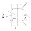
- One such configuration is that shown in the schematic drawing in Figure 1 of an aqueous electrochemical cell.
- Said cell has a working electrode collector 1 and a first insertion compound in powder form 2 in continuous electrical contact with it thereby creating a working electrode.
- a counter electrode 3 an excess of a suitable aqueous electrolyte 4, and a container 5.
- a power supply 6 is used as means for creating current flow.
- a suitable electrolyte must be prepared.
- the hydroxide of the element to be inserted is used as a salt, and water is used as a solvent.
- both the salt concentration and the pH of the electrolyte solution should be at levels such that the insertion compounds so prepared are stable in the presence of the electrolyte.
- the salt concentration and the pH are initially set at levels such that the final desired product is stable in the electrolyte.
- a current flow is then initiated using the power supply to charge the cell. This in turn results in insertion of the element into the insertion compound as ions of the element 7 and electrons 8 flow to the working electrode via the electrolyte solution and external circuit respectively. Charging is continued until the desired amount of the element is inserted. During this process, salt in the electrolyte is consumed as ions of the element are inserted into the solid insertion compound.
- the salt concentration and pH of the electrolyte must be maintained at levels such that the insertion compounds so prepared are stable in the presence of the electrolyte.
- an excess of ions of the element and [OH - ] may be used such that adequate levels of each might be maintained throughout the process without the need for replenishment.
- the concentration of both species decreases as the process proceeds.
- the concentrations of the ions of the element and [OH - ] may be increased as necessary during the process such that the insertion compounds are stable in the electrolyte as the process is carried out.
- replenishment of both species will be necessary as the electrochemical reaction proceeds.
- More than one salt may be used in the process, one perhaps to supply ions of the element and another to maintain a pH.
- a preferred choice uses only the hydroxide of the element to be inserted. In that way, the concentration of ions of the element and pH are related. A simple measurement of the pH of the electrolyte solution then provides an indicator for both and this measurement can be used to control the process.
- EMD electrochemical manganese dioxide
- Lithiated EMD is an excellent 3 V cathode material for lithium batteries.
- deposits of MnO 2 are plated onto titanium electrodes in an acid bath.
- working electrodes for the invention method are naturally prepared in the course of preparing the first insertion compound.
- the plated electrodes might then be rinsed, heat treated if desired, dipped in LiOH solution, and lithiated using the invention method.
- cell designs can be envisaged that would eliminate the need to construct a coherent working electrode out of the insertion compound.
- Such designs could include flow cells, stirred tanks where the tank itself acted as a working electrode collector, or the like where the insertion compound would make intermittent contact with the working electrode collector.
- the required levels for the salt concentration and pH in order to maintain stability are a function of the chemical potential of the inserted species in the host insertion compound. These levels can be determined empirically. However, the inventors believe that these levels can also be roughly determined using thermodynamic principles. Without being bound by theory, the inventors offer the following arguments to illustrate why insertion compounds that are not stable in water may be stable in certain aqueous solutions and also to illustrate the conditions needed for stability of the insertion compound with respect to the concentration of elemental ions and [OH - ] in such solutions.
- Equation 8 ⁇ int Li + ⁇ 0 H2O - ⁇ 0 OH- - ⁇ 0 Li+ - (1/2) ⁇ 0 H2 .
- This term is minus the partial molar free energy change for the reaction Li (s) + H 2 O (1)
- the free energy change is 51.23 Kcal/mole or 2.228 eV/atom.
- Equation 9 shows that water-unstable lithium insertion compounds, which have a voltage V versus Li metal, will react when placed in water with a resulting equilibrium pH roughly given by the solution to the equation.
- Table 1 lists the solution to Equation 9 for several pH's.
- Equation 2 suggests that high LiOH concentrations and high H 2 overpressures can cause insertion of Li in solids in aqueous solution.
- the use of high hydrogen pressures can be impractical partly as a result of safety concerns.
- the method of the invention avoids this problem).
- the first is the desired reaction: xLi + + xe - + (Li insertion compound) ⁇ Li x (Li insertion compound) (V(x)-3.04V vs S.H.E.) where V(x) is the voltage of Li x (Li insertion compound) versus metallic Li and 3.04 V is the standard electrode potential of Li ⁇ Li + + e - versus S.H.E. ('Handbook of Chemistry and Physics', CRC Press).
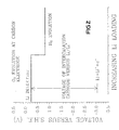
- FIG. 2 illustrates the mechanisms that occur in the electrochemical process of the invention and their voltages (for a case employing 1M LiOH electrolyte at 25°C) relative to the standard hydrogen electrode.
- V(x) constant ⁇ 2.2 V for the remaining Li.
- Li is inserted into the lithium insertion compound, forming Li x (lithium insertion compound).
- the capacity of the 2.8 V plateau is exhausted, the voltage drops to near -0.83 V versus S.H.E. or 2.22 V versus Li metal and hydrogen evolution occurs.
- the production of hydrogen at the working electrode may not be detrimental to the insertion compounds produced by the invention process. It may thus be acceptable and hence desirable to run the electrochemical cell at high current densities. This would be expected to generate large overvoltages across the working electrode possibly resulting in H 2 generation at the front of the electrode coupled with insertion occurring at the back of the electrode.
- the generation of flammable hydrogen may be avoided by restricting the insertion compounds used to those with capacity above 2.3 or 2.4 Volts versus lithium metal and by stopping the reaction just at or before the point when hydrogen production begins. In this case, it would also be important to limit the cell current density so that large overvoltages do not occur.
- Compounds prepared using the method of the invention may find practical use as a cathode material in lithium ion batteries.
- a variety of battery embodiments are possible using cathode material prepared by the method of the invention.
- Miniature laboratory batteries employing a lithium metal anode are described in the examples to follow.
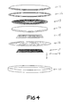
- a preferred construction for a lithium ion type system is that depicted for a commercially available spiral-wound type battery in the cross-sectional view of Figure 3.
- a jelly roll 14 is created by spirally winding a cathode foil (not shown), an anode foil (not shown), and two microporous polyolefin sheets (not shown) that act as separators.
- Cathode foils are prepared by applying a mixture of powdered lithium insertion compound prepared using the method of the invention, possibly other powdered cathode material if desired, a binder, and a conductive dilutant onto a thin aluminum foil.
- a preferred cathode material in the art is Li x Mn 2 O 4 wherein 1 ⁇ x ⁇ 2).
- the application method first involves dissolving the binder in a suitable liquid carrier. Then, a slurry is prepared using this solution plus the other powdered solid components. The slurry is then coated uniformly onto the substrate foil. Afterwards, the carrier solvent is evaporated away. Often, both sides of the aluminum foil substrate are coated in this manner and subsequently the cathode foil is calendered.
- Anode foils are prepared in a like manner except that powdered carbonaceous material (either partially graphitized carbon or graphite) is used instead of the cathode material and thin copper foil is usually used instead of aluminum.
- Anode foils are typically slightly wider than the cathode foils in order to ensure that anode foil is always opposite cathode foil. This feature is illustrated with the cathode upper edge 23, cathode lower edge 24, anode upper edge 22, and anode lower edge 25 depicted in Figure 3.
- the jelly roll 14 is inserted into a conventional battery can 13.
- a header 11 and gasket 20 are used to seal the battery 26.
- the header may include safety devices if desired.
- a combination safety vent and pressure operated disconnect device may be employed.
- Figure 3 shows one such combination that is described in detail in Canadian Patent Application CA-A-2,099,657.
- a positive thermal coefficient device PTC
- the external surface of the header 11 is also used as the positive terminal, while the external surface of the can 13 serves as the negative terminal.
- cathode tab 15 and anode tab 16 connections are made to connect the internal electrodes to the external terminals.
- Appropriate insulating pieces 12 and 17 may be inserted to prevent the possibility of internal shorting.
- electrolyte 18 is added to fill the porous spaces in the jelly roll 14.
- an electrical conditioning step involving at least the first recharge of the battery, is part of the assembly process. Again, the determination of an appropriate conditioning step along with the setting of the battery operating parameters (eg. voltage, current, and temperature limits) would be required of someone familiar with the field.
- Li metal or Li alloys may be used as the anode material.
- a miniature version of a Li metal anode based embodiment is described in the laboratory coin cell examples to follow.
- Li-Mn-O compounds A hitherto unknown phase of Li-Mn-O compounds has been discovered using the method of the invention.
- This material can be described by the formula Li x MnO 2 wherein x is a number between about 0.5 and about 1.
- the material has a layered structure described by the space group p-3m1.
- lithium can be electrochemically inserted and removed over the aforementioned range in x.
- One possible application for such a material is a cathode material in a non-aqueous battery.
- aqueous electrochemical cells like those depicted in Figure 1 were used to demonstrate certain aspects of the method of the invention.
- a lithium manganese oxide (Li-Mn-O) powder was employed as the first insertion compound.
- a working electrode was formed by sandwiching said powder between two 3mm thick titanium bars in the following manner. Each bar had about 20 uniformly spaced 2mm diameter through holes located in the lower 50mm of its length.
- a paste consisting of a mixture of Li-Mn-O powder, Super S carbon black (trade-mark product of Ensagri), and polyvinylidene fluoride (PVDF) in amounts of 87, 10, and 3% by weight respectively in N-methyl pyrollidinone (NMP) solvent was made initially. The paste was then spread onto both electrodes and was pushed into the holes as well to ensure good bonding.
- NMP N-methyl pyrollidinone
- the electrodes were clamped together so that the active layers touched, thereby making a Ti-(Li-Mn-O)-Ti sandwich.
- the paste was then dried by placing the assembly in a drying oven at 105°C in air in order to remove the NMP.
- Typical electrodes used 4.0 grams of Li-Mn-O powder and had an area of 5cm x 2.5cm. The thickness of the Li-Mn-O layer between the two Ti bars was about 4mm.
- the Li-Mn-O electrode sandwiched between the Ti bars and a carbon counter electrode were immersed to a depth of about 70mm in about 500ml of electrolyte in a pyrex beaker and the beaker was then covered with a lucite lid.
- the electrode spacing was typically about 25mm.
- the beaker was then placed in a temperature controlled oil bath. Temperatures between 16°C and 96°C could be attained.
- the electrodes were connected to a current supply. Currents ranging between 3 and 40 mA were applied to the cell. Currents were applied from 24 hours to 240 hours, depending on the synthesis.
- the number of electrons transferred to the Li-Mn-O electrode were calculated from the current, the mass of Li-Mn-O, and the current duration.
- the Ti sandwich working electrode was disassembled and the reacted powder was rinsed in alcohol.
- the powder was then dried between about 80°C and 110°C under vacuum.
- the powder was then analyzed by x-ray diffraction and evaluated in laboratory coin cell batteries.
- FIG. 4 shows an exploded view of the coin cell type battery.
- a stainless steel cap 31 and special oxidation resistant case 40 comprise the container and also serve as negative and positive terminals respectively.
- a gasket 32 is used as a seal and also serves to separate the two terminals.
- Mechanical pressure is applied to the stack comprising lithium anode 35, separator 36, and cathode 37 by means of mild steel disc spring 33 and stainless disc 34. The disc spring was selected such that a pressure of about 15 bar was applied following closure of the battery.
- the electrolyte 38 was a solution of 1M LiC10 4 salt dissolved in a solvent mixture of DMC, PC and EC in a volume ratio of 50/25/25 respectively.
- Cathodes 37 were made by uniformly coating a 20 ⁇ m thick aluminum foil substrate with a blend containing the processed mixture of Li-Mn-O powder, Super S carbon black (trade-mark) conductive dilutant, and PVDF binder plus additional ethylene propylene diene monomer (EPDM) binder. This was accomplished by initially making a slurry containing cyclohexane solvent wherein the Li-Mn-O powder, carbon black, and PVDF mixture were added to an appropriate amount of binder solution containing 4% EPDM in cyclohexane, such that 3% of the final dried electrode mass would be EPDM.
- EPDM ethylene propylene diene monomer
- Coin cell batteries were thermostatted at 30 ⁇ 1°C before testing and were then charged and discharged using constant current cyclers with ⁇ 1% current stability. Currents were adjusted to be 2.8 mA/gram of active Li-Mn-O mass for all tests. Data was logged whenever the cell voltage changed by more than 0.005 V.
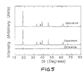
- LiMn 2 O 4 was synthesized from Li 2 CO 3 and Chemical Manganese Dioxide. Stoichiometric amounts of the reactants were mixed and reacted at 750°C in air for 24 hours. The lattice constant of this material was 8.246 ⁇ , in good agreement with the literature value (M. M. Thackeray et al, J. Electrochem. Soc., 137 , 769 (1990)). 4.0 grams of this material were sandwiched between Ti bars to make a working electrode from which an aqueous electrochemical cell was made. The electrolyte used was 2.5M LiOH. A current of 20 mA was used and 0.73 electrons per manganese were transferred to the LiMn 2 O 4 electrode at an operating temperature of 75°C.
- Figure 5 shows the measured pattern, a calculation for Li 2 Mn 2 O 4 (based on the literature values given in T. Ohzuku et al, J. Electrochem. Soc., 137 , 40 (1990) of the atom positions, lattice constants and the Space Group), and the difference between the measured and calculated patterns.
- the material produced is clearly Li 2 Mn 2 O 4 in agreement with the literature.
- a further sample V was made using LiMn 2 O 4 as the starting material.
- the aqueous electrolyte used was 1.0 LiOH .
- the current during synthesis was 2 mA and the synthesis temperature was 17°C.
- a Ag/AgCl reference electrode was also included (+0.222 V vs. S.H.E.) to confirm the proposed cell reactions and to identify the sources of cell overvoltage.
- the reference electrode was roughly positioned midway between the counter and working electrodes.
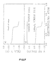
- Figure 7a shows the voltage of the aqueous cell as a function of the number of electrons/Mn transferred. (This is the difference in voltage between the carbon counter electrode and the Ti working electrode.)
- Figure 7b shows the voltage of each cell electrode versus S.H.E.
- the carbon electrode is expected to be near + 0.401 V vs. S.H.E. in the absence of overvoltages.
- the LiMn 2 O 4 -Li 2 Mn 2 O 4 voltage plateau is expected at about 2.8 V versus Li, (-0.24 V versus S.H.E.) so the cell voltage is expected to be near - 0.64 V.
- the observed cell voltage is near -0.9 V (due to overvoltages) and maintains a plateau until about 0.35 e/Mn was incorporated, at which point the potential decreases rapidly to near -1.6 V whereupon hydrogen evolution begins.
- the behaviour mimics that expected from Figure 2.
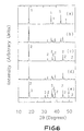
- Li 0.36 MnO 2 with ⁇ -MnO 2 structure was made by reacting LiOH.H 2 O with electrolytic manganese dioxide (TAD #1 (trade-mark) grade obtained from Mitsui) in stoichiometric amounts. The materials were thoroughly mixed as described in U.S. Patent No. 4,959,282 and were then heated at 350°C for several hours in air. The x-ray diffraction pattern of the product is shown in Figure 9. The Li 0.36 MnO 2 product was then used to fabricate a working electrode as described previously for the further insertion of Li by aqueous methods.
- TAD #1 electrolytic manganese dioxide
- the aqueous cell used 2.5M LiOH as the electrolyte and was operated at a current of 3 mA at 16°C to obtain a charge transfer of 0.5 e/Mn.
- the x-ray diffraction pattern of the resulting product is shown in Figure 10.
- the material retains the characteristic diffraction pattern of ⁇ -MnO 2 type material, but with some lattice constant changes compared to the starting material, presumably caused by the inserted Li.
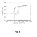
- FIG. 11 shows the voltage versus capacity for said battery, tested over several cycles. About 230 mAh/g of Li is removed during the first charging of the battery, followed by reversible cycling with near 180 mAh/g obtained.
- An electrode for an aqueous electrochemical cell was made as in Example 4.
- the aqueous cell used 2.5M LiOH electrolyte and was operated at 75°C at a current of 28 mA. A charge transfer of 0.98 e/Mn was achieved.
- the voltage of the cell corresponded to that of the lower plateau of Figure 2, where hydrogen evolution reaction is presumably carrying the current.
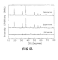
- the x-ray diffraction pattern of the product is shown in Figure 12. The pattern bears no resemblance to the pattern of the starting material shown in Figure 9.
- the Bragg peak positions correspond exactly to those of the peaks labelled 3 in figure 6e.
- the intensities and positions of the Bragg peaks are such that the product material appears to be isostructural to LiTiS 2 (J. R. Dahn et al, Can. J. Phys., 58 , 207 (1980).
- example material showed that it contained 0.87 Li atoms per Mn. Furthermore, when Mn(OH) 2 is heated to about 220°C in argon, it decomposes to MnO and H 2 O, incurring a large weight loss. By contrast, the product of this example showed little weight loss up to 500°C when heated in argon, suggesting that it contains little incorporated hydrogen.
- This Li-Mn-O product is formed slowly from spinel Li 2 Mn 2 O 4 when the voltage of the aqueous cell is allowed to reach the hydrogen evolution plateau shown in Figure 6.
- This Li-Mn-O phase apparently forms more readily from ⁇ -MnO 2 structure type material than from spinel materials.
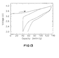
- FIG. 13 shows the voltage versus capacity behaviour of this battery. About 130 mAh/g of Li can be extracted up to 4.0 V. The material can also reversibly cycle lithium.
Description
Therefore,
| EXAMPLES OF SOLUTIONS TO EQUATION 9 | |
| V (volts) | pH |
| 2.228 | 14 |
| 2.346 | 13 |
| 2.464 | 13 |
| 2.582 | 11 |
| 2.700 | 10 |
| 2.818 | 9 |
| SYNTHESIS CONDITIONS USED FOR THE MATERIALS DESCRIBED IN EXAMPLE 2 | |||||
| In all cases, the starting insertion compound used was LiMn2O4 and the aqueous electrolyte was 2.5M LiOH. | |||||
| Sample | Current (mA) | Temperature (°C) | e/Mn | Final Products | Potential above that for H2 production? |
| I | 3.0 | 17 | 0.31 | LiMn2O4 and Li2Mn2O4 | Yes |
| II | 20.0 | 90 | 0.63 | Li2Mn2O4 | No |
| III | 20.0 | 96 | 0.75 | Li2Mn2O4 and novel phase | No |
| IV | 40.0 | 96 | 1.61 | Li2Mn2O4 and novel phase | No |
Claims (26)
- A method for preparing insertion compounds which are unstable in water itself wherein an amount of an element is inserted into a first insertion compound thereby forming a second insertion compound which are unstable in water itself, comprising:a) preparing in an electrochemical cell having a working electrode collector, a counter electrode, and a basic aqueous electrolyte, an electrolyte comprising a salt of said element dissolved in water wherein the dissolved element is at a starting concentration and the electrolyte is at a starting pH;b) electrically contacting said first insertion compound to the working electrode collector thereby forming a working electrode;c) charging said cell such that electrons and ions of said element are supplied to the working electrode; thereby inserting an amount of the element in the first insertion compound thereby forming the second insertion compound which is unstable in water itself;d) maintaining the concentration of the dissolved element in the electrolyte between the starting concentration and a final concentration; the final concentration being greater than zero and such that the second insertion compound is stable in the electrolyte;e) maintaining the pH of the electrolyte between the starting pH and a final pH; the final pH being a value such that the concentration of H+ in the electrolyte is an order of magnitude or more less than said final concentration; andf) isolating the second insertion compound from the electrolyte after insertion of the amount of the element in the first insertion compound to form the second insertion compound is complete.
- A method as in claim 1 wherein the element is an alkali metal.
- A method as in claim 1 wherein the element is an alkaline earth metal.
- A method as in claim 1 wherein the final concentration of the dissolved element in the electrolyte is greater than about 10-4 moles per liter.
- A method as in claim 1 wherein the final pH of the electrolyte is greater than 7.
- A method as in claim 1 wherein the final pH of the electrolyte is greater than about 10.
- A method as in claim 1 wherein the first insertion compound is a lithium insertion compound.
- A method as in claim 7 wherein the first insertion compound is a lithium transition metal oxide.
- A method as in claim 8 wherein the first insertion compound is a lithium manganese oxide.
- A method as in claim 9 wherein the element is lithium, the first insertion compound is the spinel LiMn2O4, and the second insertion compound is LixMn2O4 wherein x is a number and 1 < x ≤2.
- A method as in claim 9 wherein the element is lithium, the first insertion compound is LiyMnO2 with a γ-MnO2 structure wherein y is a number between about 0.2 and 4.5, and the second insertion compound is LixMnO2 wherein x is a number and y < x ≤ about 1.
- A method as in claim 11 wherein the second insertion compound is LixMnO2 having a layered structure described by the space group P-3ml.
- A method as in claim 1 wherein the electrical contact is intermittent or continuous.
- A method as in claim 1 wherein the salt is a hydroxide of said element.
- A method as in claim 14 wherein the salt is lithium hydroxide.
- A method as in claim 1 wherein the concentration of the dissolved element is maintained by further addition of said salt to the electrolyte.
- A method as in claim 1 wherein the pH of the electrolyte is maintained by further addition of said salt to the electrolyte.
- A method as in claim 1 wherein the isolation comprises rinsing the second insertion compound in a solvent and drying the compound thereafter.
- A method as in claim 18 wherein the solvent is alcohol.
- A lithium manganese oxide material with formula LixMnO2 wherein x is a number and 0.5 < x ≤ about 1, the material having a layered structure described by the space group P-3ml.
- A lithium manganese oxide material as in claim 20 wherein x is about 1 and the lattice constants of the layered structure are approximately a=3.321 Å and c=4.736 Å.
- A non-aqueous battery comprising an anode, a non-aqueous electrolyte, and a cathode comprising a second insertion compound prepared using a method as claimed in any one of claims 1,4,5,8,10,11,12, or 15, wherein the second insertion compound is a lithium manganese oxide material as claimed in claim 20 or claim 21.
- A non-aqueous battery according to claim 22 comprising an anode which is selected from lithium, lithium alloys, carbonaceous insertion compounds and other insertion compounds, a non-aqueous electrolyte, and a cathode comprising a second insertion compound prepared using a method as claimed in claims 10,11 or 12, wherein the second insertion compound is a lithium manganese oxide material as claimed in claim 20 or claim 21.
- A non-aqueous battery as claimed in claim 23 wherein the non-aqueous electrolyte comprises a lithium salt dissolved in a mixture of non-aqueous solvents.
- A non-aqueous battery as claimed in claim 24 wherein the non-aqueous electrolyte comprises LiClO4 dissolved in the mixture of non-aqueous solvents.
- A non-aqueous battery as claimed in claim 25 wherein the non-aqueous electrolyte comprises LiClO4 dissolved in a mixture of DMC, PC and EC solvents.
Applications Claiming Priority (2)
| Application Number | Priority Date | Filing Date | Title |
|---|---|---|---|
| CA002114492A CA2114492C (en) | 1994-01-28 | 1994-01-28 | Aqueous electrochemical preparation of insertion compounds and use in non-aqueous rechargeable batteries |
| CA2114492 | 1994-01-28 |
Publications (3)
| Publication Number | Publication Date |
|---|---|
| EP0669667A2 EP0669667A2 (en) | 1995-08-30 |
| EP0669667A3 EP0669667A3 (en) | 1995-09-13 |
| EP0669667B1 true EP0669667B1 (en) | 1998-04-08 |
Family
ID=4152816
Family Applications (1)
| Application Number | Title | Priority Date | Filing Date |
|---|---|---|---|
| EP94308988A Expired - Lifetime EP0669667B1 (en) | 1994-01-28 | 1994-12-02 | Aqueous electrochemical preparation of insertion compounds and use in non-aqueous rechargeable batteries |
Country Status (5)
| Country | Link |
|---|---|
| US (2) | US5599435A (en) |
| EP (1) | EP0669667B1 (en) |
| JP (1) | JPH07223819A (en) |
| CA (1) | CA2114492C (en) |
| DE (1) | DE69409499T2 (en) |
Families Citing this family (17)
| Publication number | Priority date | Publication date | Assignee | Title |
|---|---|---|---|---|
| US5871865A (en) | 1997-05-15 | 1999-02-16 | Valence Technology, Inc. | Methods of fabricating electrochemical cells |
| DE69838169T2 (en) * | 1997-05-27 | 2008-04-17 | Tdk Corp. | METHOD FOR PRODUCING AN ELECTRODE FOR NONATURATED ELECTROLYTE BATTERY |
| KR100268749B1 (en) * | 1998-02-26 | 2000-10-16 | 이 병 길 | Layered manganese dioxide for li secondary batteries and method for producing the same |
| US5939043A (en) * | 1998-06-26 | 1999-08-17 | Ga-Tek Inc. | Process for preparing Lix Mn2 O4 intercalation compounds |
| US6110622A (en) | 1998-07-22 | 2000-08-29 | Wilson Greatbatch Ltd. | Chemically machined current collector design |
| US6245464B1 (en) | 1998-09-21 | 2001-06-12 | Wilson Greatbatch Ltd. | Hermetically sealed lithium-ion secondary electrochemical cell |
| US6280873B1 (en) | 1999-04-08 | 2001-08-28 | Quallion, Llc | Wound battery and method for making it |
| JP4274630B2 (en) * | 1999-05-21 | 2009-06-10 | 三井金属鉱業株式会社 | Method for producing spinel type lithium manganate |
| US7189475B2 (en) * | 2000-07-27 | 2007-03-13 | Kabushiki Kaisha Toyota Chuo Kenkyusho | Lithium secondary battery |
| US20050164085A1 (en) * | 2004-01-22 | 2005-07-28 | Bofinger Todd E. | Cathode material for lithium battery |
| US9133554B2 (en) | 2006-02-08 | 2015-09-15 | Dynamic Food Ingredients Corporation | Methods for the electrolytic production of erythritol |
| US7955489B2 (en) * | 2006-02-08 | 2011-06-07 | Dynamic Food Ingredients Corporation | Methods for the electrolytic production of erythrose or erythritol |
| FR2920255B1 (en) * | 2007-08-24 | 2009-11-13 | Commissariat Energie Atomique | LITHIUM ELECTROCHEMICAL GENERATOR OPERATING WITH AQUEOUS ELECTROLYTE. |
| US8945756B2 (en) | 2012-12-12 | 2015-02-03 | Aquion Energy Inc. | Composite anode structure for aqueous electrolyte energy storage and device containing same |
| US9711792B2 (en) | 2014-03-10 | 2017-07-18 | Hitachi, Ltd. | Positive electrode active material for secondary batteries and lithium ion secondary battery using the same |
| EP3353844B1 (en) | 2015-03-27 | 2022-05-11 | Mason K. Harrup | All-inorganic solvents for electrolytes |
| US10707531B1 (en) | 2016-09-27 | 2020-07-07 | New Dominion Enterprises Inc. | All-inorganic solvents for electrolytes |
Family Cites Families (11)
| Publication number | Priority date | Publication date | Assignee | Title |
|---|---|---|---|---|
| DE3068002D1 (en) * | 1979-04-05 | 1984-07-05 | Atomic Energy Authority Uk | Electrochemical cell and method of making ion conductors for said cell |
| US4507371A (en) * | 1982-06-02 | 1985-03-26 | South African Inventions Development Corporation | Solid state cell wherein an anode, solid electrolyte and cathode each comprise a cubic-close-packed framework structure |
| US4731309A (en) * | 1985-06-14 | 1988-03-15 | The Dow Chemical Company | High rate and high energy density cell |
| US4959282A (en) * | 1988-07-11 | 1990-09-25 | Moli Energy Limited | Cathode active materials, methods of making same and electrochemical cells incorporating the same |
| GB2251119B (en) * | 1990-12-20 | 1995-06-07 | Technology Finance Corp | Electrochemical cell |
| US5219679A (en) * | 1991-01-17 | 1993-06-15 | Eic Laboratories, Inc. | Solid electrolytes |
| DE4101533A1 (en) * | 1991-01-19 | 1992-07-23 | Varta Batterie | ELECTROCHEMICAL SECONDARY ELEMENT |
| US5196279A (en) * | 1991-01-28 | 1993-03-23 | Bell Communications Research, Inc. | Rechargeable battery including a Li1+x Mn2 O4 cathode and a carbon anode |
| US5316875A (en) * | 1991-07-19 | 1994-05-31 | Matsushita Electric Industrial Co., Ltd. | Secondary battery with nonaqueous electrolyte and method of manufacturing same |
| JP3059832B2 (en) * | 1992-07-27 | 2000-07-04 | 三洋電機株式会社 | Lithium secondary battery |
| ZA936168B (en) * | 1992-08-28 | 1994-03-22 | Technology Finance Corp | Electrochemical cell |
-
1994
- 1994-01-28 CA CA002114492A patent/CA2114492C/en not_active Expired - Fee Related
- 1994-12-02 DE DE69409499T patent/DE69409499T2/en not_active Expired - Fee Related
- 1994-12-02 EP EP94308988A patent/EP0669667B1/en not_active Expired - Lifetime
-
1995
- 1995-01-25 US US08/377,951 patent/US5599435A/en not_active Expired - Lifetime
- 1995-01-25 JP JP7009558A patent/JPH07223819A/en active Pending
-
1996
- 1996-12-19 US US08/769,668 patent/US5733681A/en not_active Expired - Lifetime
Also Published As
| Publication number | Publication date |
|---|---|
| JPH07223819A (en) | 1995-08-22 |
| DE69409499T2 (en) | 1998-07-30 |
| US5733681A (en) | 1998-03-31 |
| EP0669667A2 (en) | 1995-08-30 |
| CA2114492A1 (en) | 1995-07-29 |
| CA2114492C (en) | 2000-09-05 |
| DE69409499D1 (en) | 1998-05-14 |
| EP0669667A3 (en) | 1995-09-13 |
| US5599435A (en) | 1997-02-04 |
Similar Documents
| Publication | Publication Date | Title |
|---|---|---|
| CA2114493C (en) | Method for increasing the reversible capacity of lithium transition metal oxide cathodes | |
| US5882218A (en) | Lithium manganese oxide insertion compounds and use in rechargeable batteries | |
| CA2158242C (en) | High voltage insertion compounds for lithium batteries | |
| US5948569A (en) | Lithium ion electrochemical cell | |
| EP0656667B1 (en) | Inverse spinel compounds as cathodes for lithium batteries | |
| Li et al. | Lithium intercalation from aqueous solutions | |
| JP4301527B2 (en) | Aqueous rechargeable battery | |
| EP1056143B1 (en) | Rechargeable spinel lithium batteries with improved elevated temperature cycle life | |
| EP0669667B1 (en) | Aqueous electrochemical preparation of insertion compounds and use in non-aqueous rechargeable batteries | |
| US8313859B2 (en) | Battery cathodes | |
| US5700597A (en) | Method for preparing Li1+x Mn2-x-y My O4 for use in lithium batteries | |
| US5514490A (en) | Secondary lithium battery using a new layered anode material | |
| JP7121219B1 (en) | Method for producing lithium metal composite oxide | |
| EP4203105A1 (en) | Positive electrode active material for lithium secondary batteries, positive electrode for lithium secondary batteries, and lithium secondary battery | |
| US8137842B2 (en) | Battery cathodes | |
| WO2003058732A1 (en) | New electrode materials for a rechargeable electrochemical cell |
Legal Events
| Date | Code | Title | Description |
|---|---|---|---|
| PUAI | Public reference made under article 153(3) epc to a published international application that has entered the european phase |
Free format text: ORIGINAL CODE: 0009012 |
|
| PUAL | Search report despatched |
Free format text: ORIGINAL CODE: 0009013 |
|
| AK | Designated contracting states |
Kind code of ref document: A2 Designated state(s): DE FR GB |
|
| AK | Designated contracting states |
Kind code of ref document: A3 Designated state(s): DE FR GB |
|
| 17P | Request for examination filed |
Effective date: 19960216 |
|
| 17Q | First examination report despatched |
Effective date: 19960604 |
|
| GRAG | Despatch of communication of intention to grant |
Free format text: ORIGINAL CODE: EPIDOS AGRA |
|
| GRAG | Despatch of communication of intention to grant |
Free format text: ORIGINAL CODE: EPIDOS AGRA |
|
| GRAH | Despatch of communication of intention to grant a patent |
Free format text: ORIGINAL CODE: EPIDOS IGRA |
|
| GRAH | Despatch of communication of intention to grant a patent |
Free format text: ORIGINAL CODE: EPIDOS IGRA |
|
| GRAA | (expected) grant |
Free format text: ORIGINAL CODE: 0009210 |
|
| AK | Designated contracting states |
Kind code of ref document: B1 Designated state(s): DE FR GB |
|
| REF | Corresponds to: |
Ref document number: 69409499 Country of ref document: DE Date of ref document: 19980514 |
|
| ET | Fr: translation filed | ||
| PLBE | No opposition filed within time limit |
Free format text: ORIGINAL CODE: 0009261 |
|
| STAA | Information on the status of an ep patent application or granted ep patent |
Free format text: STATUS: NO OPPOSITION FILED WITHIN TIME LIMIT |
|
| 26N | No opposition filed | ||
| PGFP | Annual fee paid to national office [announced via postgrant information from national office to epo] |
Ref country code: FR Payment date: 20011120 Year of fee payment: 8 |
|
| PGFP | Annual fee paid to national office [announced via postgrant information from national office to epo] |
Ref country code: GB Payment date: 20011122 Year of fee payment: 8 |
|
| PGFP | Annual fee paid to national office [announced via postgrant information from national office to epo] |
Ref country code: DE Payment date: 20011123 Year of fee payment: 8 |
|
| REG | Reference to a national code |
Ref country code: GB Ref legal event code: IF02 |
|
| PG25 | Lapsed in a contracting state [announced via postgrant information from national office to epo] |
Ref country code: GB Free format text: LAPSE BECAUSE OF NON-PAYMENT OF DUE FEES Effective date: 20021202 |
|
| PG25 | Lapsed in a contracting state [announced via postgrant information from national office to epo] |
Ref country code: DE Free format text: LAPSE BECAUSE OF NON-PAYMENT OF DUE FEES Effective date: 20030701 |
|
| GBPC | Gb: european patent ceased through non-payment of renewal fee | ||
| PG25 | Lapsed in a contracting state [announced via postgrant information from national office to epo] |
Ref country code: FR Free format text: LAPSE BECAUSE OF NON-PAYMENT OF DUE FEES Effective date: 20030901 |
|
| REG | Reference to a national code |
Ref country code: FR Ref legal event code: ST |