EP0669042B1 - Extended cycle-life metal hydride battery for electric vehicles - Google Patents
Extended cycle-life metal hydride battery for electric vehicles Download PDFInfo
- Publication number
- EP0669042B1 EP0669042B1 EP94900539A EP94900539A EP0669042B1 EP 0669042 B1 EP0669042 B1 EP 0669042B1 EP 94900539 A EP94900539 A EP 94900539A EP 94900539 A EP94900539 A EP 94900539A EP 0669042 B1 EP0669042 B1 EP 0669042B1
- Authority
- EP
- European Patent Office
- Prior art keywords
- hydrogen
- battery cell
- battery
- water
- metal hydride
- Prior art date
- Legal status (The legal status is an assumption and is not a legal conclusion. Google has not performed a legal analysis and makes no representation as to the accuracy of the status listed.)
- Expired - Lifetime
Links
Images
Classifications
-
- H—ELECTRICITY
- H01—ELECTRIC ELEMENTS
- H01M—PROCESSES OR MEANS, e.g. BATTERIES, FOR THE DIRECT CONVERSION OF CHEMICAL ENERGY INTO ELECTRICAL ENERGY
- H01M8/00—Fuel cells; Manufacture thereof
- H01M8/06—Combination of fuel cells with means for production of reactants or for treatment of residues
- H01M8/0606—Combination of fuel cells with means for production of reactants or for treatment of residues with means for production of gaseous reactants
- H01M8/065—Combination of fuel cells with means for production of reactants or for treatment of residues with means for production of gaseous reactants by dissolution of metals or alloys; by dehydriding metallic substances
-
- H—ELECTRICITY
- H01—ELECTRIC ELEMENTS
- H01M—PROCESSES OR MEANS, e.g. BATTERIES, FOR THE DIRECT CONVERSION OF CHEMICAL ENERGY INTO ELECTRICAL ENERGY
- H01M12/00—Hybrid cells; Manufacture thereof
- H01M12/08—Hybrid cells; Manufacture thereof composed of a half-cell of a fuel-cell type and a half-cell of the secondary-cell type
-
- H—ELECTRICITY
- H01—ELECTRIC ELEMENTS
- H01M—PROCESSES OR MEANS, e.g. BATTERIES, FOR THE DIRECT CONVERSION OF CHEMICAL ENERGY INTO ELECTRICAL ENERGY
- H01M10/00—Secondary cells; Manufacture thereof
- H01M10/34—Gastight accumulators
- H01M10/345—Gastight metal hydride accumulators
-
- Y—GENERAL TAGGING OF NEW TECHNOLOGICAL DEVELOPMENTS; GENERAL TAGGING OF CROSS-SECTIONAL TECHNOLOGIES SPANNING OVER SEVERAL SECTIONS OF THE IPC; TECHNICAL SUBJECTS COVERED BY FORMER USPC CROSS-REFERENCE ART COLLECTIONS [XRACs] AND DIGESTS
- Y02—TECHNOLOGIES OR APPLICATIONS FOR MITIGATION OR ADAPTATION AGAINST CLIMATE CHANGE
- Y02E—REDUCTION OF GREENHOUSE GAS [GHG] EMISSIONS, RELATED TO ENERGY GENERATION, TRANSMISSION OR DISTRIBUTION
- Y02E60/00—Enabling technologies; Technologies with a potential or indirect contribution to GHG emissions mitigation
- Y02E60/10—Energy storage using batteries
-
- Y—GENERAL TAGGING OF NEW TECHNOLOGICAL DEVELOPMENTS; GENERAL TAGGING OF CROSS-SECTIONAL TECHNOLOGIES SPANNING OVER SEVERAL SECTIONS OF THE IPC; TECHNICAL SUBJECTS COVERED BY FORMER USPC CROSS-REFERENCE ART COLLECTIONS [XRACs] AND DIGESTS
- Y02—TECHNOLOGIES OR APPLICATIONS FOR MITIGATION OR ADAPTATION AGAINST CLIMATE CHANGE
- Y02E—REDUCTION OF GREENHOUSE GAS [GHG] EMISSIONS, RELATED TO ENERGY GENERATION, TRANSMISSION OR DISTRIBUTION
- Y02E60/00—Enabling technologies; Technologies with a potential or indirect contribution to GHG emissions mitigation
- Y02E60/30—Hydrogen technology
- Y02E60/50—Fuel cells
Definitions
- the present invention relates generally to a metal hydride battery and more specifically relates to increasing the cycle life of a metal hydride battery by improving the battery hydrogen storage capability.
- U.S. Patent No. 5,047,301 assigned to a subsidiary company of the assignee of the present invention, is drawn to a high temperature battery utilizing a connection between the battery and the source of hydrogen. That battery only begins operation when it is exposed to the hydrogen gas which passes through piping after the connection between the battery and the hydrogen source is made.
- the battery disclosed in U.S. Patent No. 5,047,301 operates only so long as there is hydrogen being discharged from the hydrogen source, and stops operating when the flow of hydrogen either is discontinued or the hydrogen is depleted.
- This type of battery performs well in conditions where battery operation is necessarily automatic, such as in space or in a deep well environment, where manual intervention or monitoring is difficult, at best, and continued electrical power over long periods of time is not necessary.
- Ni-H 2 nickel-hydrogen
- a nickel hydrogen cell is disclosed in U.S. Patent No. 3,850,694, utilizing a reversible electrolytic reaction wherein Ni(OH) 2 and OH - are converted to NiOOH, H 2 O and an electron.
- Reference to U.S. Patent No. 3,850,694 is made for teaching of the electrochemical process occurring in these types of batteries. Because of the high initial cost of manufacture, implementation of Ni-H 2 battery systems has not been cost-efficient except for certain esoteric uses, such as a power source in space.
- Ni-H 2 battery systems for terrestrial uses has been a subject of study by government agencies and private concerns.
- a method of removing oxygen and water impurities from a hydrogen gas stream using a filter system is disclosed in U.S. Patent No. 4,343,770.
- the system consists of an adsorbent for filtering out water from a hydrogen stream.
- the system which is disclosed further includes an elaborate network of piping and valve means for directing hydrogen flow through the filter means and into and out of the hydrogen consuming device, which, in the preferred embodiment, is an internal combustion engine utilizing gaseous hydrogen as the fuel.
- Nickel hydride batteries such as those disclosed in U.S. Patent Nos. 3,850,694 and 5,047,301, as well as ambient temperature hydride batteries, which are generally available from Eagle Picher Industries of Joplin, Missouri, utilize an electrolyte which must be in a moist condition so as to maintain its conductivity. Great care must be taken with the amount of water available in the cell, as is discussed in U.S. Patent No. 3,850,964. During battery discharge, the electrolytic reaction breaks down the gaseous hydrogen to form water, thus maintaining cell moisture.
- the battery cell produces gaseous hydrogen from the discharge reaction which also contains some evaporated water.
- gaseous hydrogen from the discharge reaction which also contains some evaporated water.
- the water condenses on the elements of the battery cell and maintains the conductivity of the electrolyte, which is necessary for the battery to continue providing electrical power.
- some means is necessary to maintain the moisture in the electrolyte by a mechanism which tends to force the water vapor toward the battery side of a separated hydrogen storage vessel/hydride battery cell.
- a battery system and method of use thereof which utilizes a stream of hydrogen for generating electrical power on demand, comprising a hydrogen storage vessel having at least one opening and a metal hydride bed disposed therein, the metal hydride bed being able to absorb hydrogen under certain conditions and to release hydrogen under other conditions, a battery cell enclosed in an enclosure comprising an electrolyte and an oxidant, the enclosure of the battery cell having at least one opening, in-line piping means having at least two ends, one end being sealingly connected to the hydrogen storage vessel opening and the other end being sealingly connected to the battery cell opening, a predetermined quantity of hydrogen which is disposed within the system, whereby during discharging of the battery cell, the hydrogen is impelled to flow in a stream from the hydrogen storage vessel to the battery cell and during recharging of the battery cell, the hydrogen stream is impelled to flow from the battery cell to the hydrogen storage vessel, a catalytic converter disposed in-line between the battery cell and the hydride bed, and a mo
- the system 10 of the preferred embodiment comprises a nickel-hydrogen battery cell 12 having a positive electrode 14 and a negative electrode 16.
- the precise construction of the cell is not overly significant to the invention.
- the cell 12 may be one that is generally known or may be of special construction. It should be appreciated that the only requirement is that the fuel for the cell is hydrogen, and any metal-hydrogen battery cell may use the teachings of this invention.
- an exemplary cell could be made in accordance with the teaching of U.S. Patent No. 4,699,856.
- the cell may consist of a conventional Ni-KOH cell wherein KOH is used as the electrolyte, as is described in U.S. Patent No. 3,850,694.
- the cell 12 is in fluid communication with other elements of the system through a hermetically sealed piping means 20.
- the piping means 20 provides fluid communication throughout the complete system, connecting all of the elements in an in-line connection.
- the in-line connection defined by piping means 20 provides the path for transmission of gas through the system.
- the gas being transmitted is hydrogen and the piping means 20 is a singular, but linearly segmented, means for the transmission of the hydrogen.
- an optional heat exchanger 24 is provided to cool off the gaseous hydrogen which is being transmitted to the battery cell 12 during a discharge step of the battery system.
- the next element in the system, in-line with the piping means 20, is a catalytic converter 24 for converting O 2 molecules, in combination with hydrogen from the gaseous stream, into water. Stray oxygen molecules may find their way into the system, even if it is hermetically sealed, as a result of the electrolytic reaction which occurs in the battery cell 12.
- Catalytic converter 24 is shown in cross-sectional detail in Fig. 2.
- Catalytic converter 24 comprises a housing 26, which may be cylindrical, and a catalyst 28 in the form of thin strands of wire.
- the wire comprise one of several elements known to be good catalysts, such as platinum, palladium and nickel.
- Exemplary catalytic converters, such as oxygen removing purifiers, may be obtained from Matheson Gas Products Company in East Rutherford, New Jersey.
- the catalytic converter 24 is operational only during the recharging step of the battery system, when the gaseous hydrogen is transmitted from the battery cell 12 through the piping means 20 for storage. Referring to Figs. 1 and 2, during recharging, the hydrogen gas is transmitted from the right toward the left. After passing through the catalytic converter 24, the hydrogen stream should contain only H 2 molecules and water vapor, H 2 O. The hydrogen stream is referred to as being "wet" and next passes through dryer 30, which removes the water vapor from the hydrogen.
- FIG. 2 An appropriate drying means is illustrated in cross section in Fig. 2 and takes the form of a molecular sieve dryer 30.
- a molecular sieve dryer is commercially available from the Linde Division of Union Carbide Corporation, Somerset, New Jersey.
- the Linde Model 4A molecular sieve, having a nominal pore diameter of 4A, has been found to work best in removing water from the hydrogen stream.
- an exemplary molecular sieve dryer 30 comprises a chamber 31 defined by a chamber wall 32 having an internal layer of thermally insulating material 34.
- the thermal insulation is optional, but assists in avoiding loss of thermal energy during battery discharge.
- the chamber 31 provides an opening 36 which, during battery recharging, introduces the "wet" hydrogen into the chamber 31, and a second opening 38, at an end opposite to opening 36, for expelling the "dry" hydrogen stream from the chamber 31 after it has passed through the molecular sieve 30.
- the openings 36,38 are, of course, hermetically sealed to the segments of piping means 20, enclosing and hermetically sealing the chamber 31 within the system 10 together with all of the other elements.
- Chamber 31 encloses the operational elements of the molecular mole sieve dryer 30, which elements comprise adsorbent 40 having precisely uniform sizes and dimensions, and which provide numerous minute passageways that permit passage of the H 2 molecules but filter out the larger H 2 O molecules.
- the adsorbent 40 is usually a water adsorbing zeolite, of general formula M 2/n O ⁇ Al 2 O 3 ⁇ xSiO 2 ⁇ yH 2 O where M is an appropriate cation of n valance and y is the number of adsorbed water molecules.
- M is an appropriate cation of n valance
- y is the number of adsorbed water molecules.
- Na 12 [(AlO 2 ) 12 (SiO 2 ) 12 ] ⁇ 27H 2 O provides good water adsorbing characteristics.
- the adsorbent 40 is a static desiccant and can be packed in chamber 31 in the form of powder, pellets, mesh or beads.
- the preferred embodiment includes beads with an impregnated saturation indicator mechanism, such as a view port covered by a clear window 42.
- the window 42 may be made of glass and is sealed to the chamber wall 32.
- the indicator comprises a chemical impregnated into the adsorbent 40.
- the adsorbent is in the form of beads to which the impregnated chemical imparts a blue color when the adsorbent 40 is fully activated by the removal of the water of hydration.
- the blue color will turn pink as water is adsorbed.
- the pink color indicates the saturation point of the adsorbent 40, and in use with the present invention, denotes when the system 10 is operating properly during recharging of the battery.
- the indicating adsorbent 40 will turn from a pinkish to a bluish color. Conversely, during recharging of the battery cell 12, the adsorbent 40 will turn from blue to pink as water is absorbed.
- the port window 42 should be disposed within the chamber wall 32 to provide a clear and easy view of the indicating adsorbent material 40 when the device is being monitored.
- an electrical resistance heating wire 44 Disposed in a looping pattern within the adsorbent 40 is an electrical resistance heating wire 44, comprising a known material such as nichrome.
- the electrical heating wire 44 is connected at both of its ends to a power source (not shown) through two electrically insulated leads 46.
- the power source may be the nickel hydride cell 12 during the discharging step, and the heating wire 44 may consume about 2.5-5.0% of the power of cell 12.
- the layer of insulating material 34 is important in maintaining the heat provided by wire 44 within the chamber 31.
- a control switch 48 which may be automatically or manually operated, is provided for introducing or shutting off electrical power to the resistance heating wire 44 when it is needed during the operation of the system 10.
- the final segment of the piping means 20 extends to a valve 49 and then to the hydrogen storage container 50, as shown in Fig. 1.
- the container 50 is a sealed chamber enclosing a porous bed of a metal hydride material 52 having a high capacity for hydrogen storage.
- the valve 49 may be a manually operated valve or a solenoid valve, and when closed, effectively seals the container 50. Proper use of valve 49 operates to remove the unwanted, self discharge of the metal hydrogen battery cell, which has been a difficulty encountered in the past.
- a significant feature of the present invention is providing a dry, oxygen-free hydrogen gas stream, which is obtained after the hydrogen passes through the catalytic converter 24 and the molecular sieve dryer 30.
- the hydrogen stream, cleaned of impurities, is much less destructive of the metal hydride materials making up the hydride bed 52.
- inexpensive hydride materials can supplant the very expensive, exotic, water-impermeable hydride materials in present use with hydride batteries.
- the use of LaNi 5 H X hydride material is contemplated.
- the electrolytic reaction is a reversible reaction, that is, the discharge step introduces hydrogen and produces a net result of electricity (electrons) and water as a by-product.
- the reaction can be driven in the reverse direction during recharging, where an external electric power source introduces electrons which are then used to produce H 2 and OH - radicals from the available water.
- the reaction is well known for the case of nickel hydrogen, as is documented in technical treatises, such as the "Handbook of Batteries and Fuel Cells," ed. D. Linden, McGraw-Hill Book Co., New York, NY, ch.22, pp.22-2.
- Valve 49 may be a solenoid valve which opens automatically when electrical power is needed from the battery.
- the valve 49 may contain the H 2 under some low pressure, approximately 10-20 psi above atmospheric pressure which develops when the battery cell gives off hydrogen gas during the previous recharging step.
- the nickel hydride cell 12 consumes hydrogen, and a hydrogen pressure differential develops between the hydrogen storage vessel 50 and the cell 12. This pressure differential tends to force a stream of gaseous hydrogen to flow toward the cell 12.
- the hydrogen in cell 12 As the hydrogen in cell 12 is consumed, the hydrogen partial pressure around the hydride bed 52 falls below the equilibrium pressure of the hydride material, and the hydride bed exudes more hydrogen into the vessel 50. It is well known in the hydride field that the equilibrium pressure may be predetermined by different initial parameters so that the hydride continues to give off hydrogen until a majority, approximately 80%, of the capacity of the nickel hydride cell 12 is depleted. Alternatively, heat may be provided to the metal hydride bed 52, which heat is available from an external source as waste heat or even may be generated by the nickel hydride battery cell 12 itself. Heating the hydride bed 52 will release H 2 into the vessel 50 and through the piping means 20 to pass into the resistance-heated molecular sieve dryer 30. The heating of the hydride bed 52 may be used as an emergency fuel supply, such as a reserve amount of power necessary to travel to the next recharging point.
- the hydrogen stream becomes wet as the hydrogen is returned to the battery cell 12.
- Return of the water vapor to battery cell 12 provides moisture to the electrolyte in the cell in order to maintain the contact between the cell elements.
- recharging of the battery cell tends to drive out the gaseous hydrogen which results from the reverse electrolytic reaction by developing hydrogen pressure in the battery cell 12.
- a pressure differential builds up from the hydrogen in the cell 12, and gaseous hydrogen is forced out into the first segment of pipe means 20.
- water vapor which has evaporated into the hydrogen gas stream is also expelled from the battery cell 12. Repeated recharging of the system 10 eventually tends to dry out the electrolyte in cell 12. The cell then fails to provide any electric current because no contact is made by the elements within the cell.
- One feature of this invention is that during recharging, the electric heating wire 44 evaporates the residual water in the adsorbent 40 and the water vapor is then deposited within the electrolyte of cell 12. Maintaining the moisture of the cell elements provides a more efficient operation of the cell during discharge and is an improvement over prior art devices.
- the hydrogen stream continues to travel through the in-line pipe means 20 to the heat exchanger 22, shown in Fig. 1.
- the heat exchanger 22 is an optional element which may be used to cool the hydrogen. It has been found that cooling the hydrogen tends to produce the temperature of the hydrogen stream to ambient temperatures. Cooling the hydrogen stream is desirable for driving the electrolytic reaction in the battery cell 12 during discharge. Entrance of the cool hydrogen into the cell 12 drives the electrolytic reaction which produces a potential across the electrodes 14,16.
- a circuit connection to an electrical load across the electrodes 14,16 will then begin the flow of current from the cell 12, which current production continues conversion of the hydrogen to water.
- the drop in the hydrogen pressure in the cell 12 causes a pressure differential which tends to push more hydrogen from the hydrogen storage vessel 50 into the in-line stream and through the pipe means 20 to the battery cell 12.
- the reaction proceeds and the hydrogen continues to flow as long as electrical current is consumed by the circuit and load (not shown).
- the circuit through the electrodes 14,16 which is connected to a load (not shown), can be broken. In that case, the electrolytic reaction proceeds until it reaches an equilibrium. During equilibrium conditions, as much hydrogen is converted to water as is the water which becomes hydrogen. At the equilibrium point of the reaction, the consumption of gaseous hydrogen stops and a hydrogen pressure equilibrium between the cell 12 and the hydrogen storage vessel 50 develops. With a constant pressure, there is also an equilibrium point which develops between the metal hydride bed 52 and the hydrogen in the vessel 50. Thus, all of the various components remain at equilibrium and the system remains static with no hydrogen flow between the elements.
- shutoff valve 49 A similar result may be reached by shutting off of the optional valve 49, which will also cut off the hydrogen flow and isolate the two separate reversible reactions, that of the electrolytic reaction in the cell 12 and of the hydrogen desorption reaction from the hydride bed 52 in the vessel 50.
- One advantage of a shutoff valve 49 is that the operation of system 10 may be stopped immediately in case of emergency, such as if a hydrogen leak develops. Also, as described above, a shutoff valve 49 removes problems which may otherwise develop due to the unwanted self discharge of the battery cell 12.
- the recharge step first requires a source of steady electric power.
- a source may be a power grid, such as is generally available.
- Another possible source is regular stations for recharging batteries which are utilized in an automobile. It is contemplated that an automobile which operates on a large battery made according to the present invention may be able to recharge while on the road at a station which provides a recharging service.
- the source of electric power may be a solar panel which may provide electric power to a first battery during daylight hours.
- a photovoltaic system is capable of charging a primary metal hydride battery cell and storing the hydrogen gas evolved from the reverse electrolytic reaction in an identical manner to that of a conventional recharge system.
- a user may utilize the automobile with a first battery during one day, and an alternate battery may be utilized on a subsequent day while the first battery is recharging.
- recharging of the system 10 begins by introducing electrons to the negative electrode 16, in effect making it a positive electrode and thus reversing the electrolytic reaction described above.
- the reverse reaction results in the conversion of the water, left in the cell 12 as a by-product, into hydrogen and hydroxyl ions (OH - ).
- the hydroxyl ions remain in solution, and are the negatively charged half of the KOH salt which was originally an element of the battery cell.
- the hydrogen forms H 2 molecules which collects in cell 12 as a gas. Continued collection of the hydrogen increases the hydrogen gas pressure and impels the hydrogen into the first segment of the piping means 20.
- the hydrogen gas is not affected by the heat exchanger 22 as it travels in a stream through the heat exchanger 22, because the heat exchanger 22 is not operated during the recharging cycle.
- the hydrogen stream continues to flow through the system 10, from right to left in Figs. 1 and 2, and reaches the catalytic converter 24.
- the hydrogen stream at this point may include oxygen molecules which can appear in the system as trace impurities from the electrolytic reaction. For example, two OH - ions may join to obtain O 2 . These trace amounts of O 2 cause deterioration of the metal hydride bed 52 after repeated cycles if the oxygen is permitted to reach the hydride material. Continued use of the system without oxygen removal results in excessive oxygen deterioration of the metal hydride material in bed 52.
- the catalytic converter 24 converts all of the O 2 molecules by combining with hydrogen from the passing hydrogen stream to form water molecules, H 2 O.
- the water evaporates into the H 2 stream and is borne along as water vapor within the stream.
- the hydrogen in the in-line pipe means 20 is wet before reaching the dryer 30, as is explained above.
- the dry hydrogen stream then continues through the pipe means 20 and into the hydrogen storage vessel 50.
- the equilibrium of the hydriding process in the hydride bed 52 is altered. That is, as the pressure builds up, the metal hydride bed absorbs more hydrogen because the hydrogen pressure in the vessel 50 exceeds the equilibrium pressure of the hydriding process.
- the hydrogen pressure in the vessel 50 becomes lower than the hydrogen pressure in the cell 12, which is continuing to produce H 2 molecules as a result of the reverse electrolytic reaction. That difference in the hydrogen pressure develops a pressure differential and results in the stream of hydrogen gas which is transmitted from the cell 12 by the pipe means 20 through the catalytic converter 24 and the dryer 30 into the vessel 50.
- the stream of gaseous hydrogen will continue until the battery cell 12 is completely recharged.
- the completion of the recharge cycle can be sensed and indicated by a known mechanism, such as when the potential or power available in the cell 12 reaches a certain level.
- the electrical power source (not shown) is removed from the battery cell 12, and all elements of the system 10 are allowed to return to equilibrium.
- the valve 49 may also be shut down, thus isolating the hydrogen stored in bed 52 from the remainder of the system 10.
- the hydrogen pressure in the remainder of the system 10 then reaches an equilibrium in the battery cell 12 in accordance with the electrolytic reaction set forth above. It should be noted, however, that the potential across the electrodes 14 and 16 is maintained even though the battery cell 12 does not comprise a part of an electrical circuit. If the battery cell 12 is not immediately utilized, maintaining the potential across the electrodes 14,16 will eventually drain the electrolytic reaction until all of the hydrogen which is available in the cell 12 and pipe means 20 is dissipated. Proper design of the system 10 will minimize the volume of hydrogen available in this space. When the gaseous hydrogen is completely dissipated in the electolytic reaction, the hydrogen pressure in the cell 12 falls to a level at or near atmospheric pressure but, in any case, less than the hydrogen pressure in the hydrogen storage vessel 50. The system 10 is now ready for use.
- the battery cell 12 is not in operation and there is no potential across the electrodes 14,16.
- the unique construction of this battery system 10 thus increases the sheft life of the battery cell 12 for an indefinite amount of time, and the system 10 remains as ready for use months or years after it has been charged as it is immediately after it has been recharged.
- the inventive system may undergo a much greater number of cycles because the hydride bed 52 is protected from oxygen which destroys the ability of the metal hydride material to retain and store large amounts of hydrogen.
- the catalytic converter 24, and molecular sieve 30 may be disposed in a chamber (not shown) within vessel 50 which is isolated from the hydride bed 52.
- This type of integral storage vessel 50 may be removed and replaced by a new one, while the hydride bed 52, the molecular sieve dryer 30 and the catalytic converter 24 are all reconditioned for recycled use.
Landscapes
- Engineering & Computer Science (AREA)
- Manufacturing & Machinery (AREA)
- Chemical & Material Sciences (AREA)
- Chemical Kinetics & Catalysis (AREA)
- Electrochemistry (AREA)
- General Chemical & Material Sciences (AREA)
- Life Sciences & Earth Sciences (AREA)
- Sustainable Development (AREA)
- Sustainable Energy (AREA)
- Fuel Cell (AREA)
- Hybrid Cells (AREA)
- Filling, Topping-Up Batteries (AREA)
Abstract
Description
- The present invention relates generally to a metal hydride battery and more specifically relates to increasing the cycle life of a metal hydride battery by improving the battery hydrogen storage capability.
- Metal hydride batteries have been used in wide-ranging applications where a reliable, self-contained source of electric power is needed in a location which is generally inaccessible. U.S. Patent No. 5,047,301, assigned to a subsidiary company of the assignee of the present invention, is drawn to a high temperature battery utilizing a connection between the battery and the source of hydrogen. That battery only begins operation when it is exposed to the hydrogen gas which passes through piping after the connection between the battery and the hydrogen source is made. The battery disclosed in U.S. Patent No. 5,047,301 operates only so long as there is hydrogen being discharged from the hydrogen source, and stops operating when the flow of hydrogen either is discontinued or the hydrogen is depleted. This type of battery performs well in conditions where battery operation is necessarily automatic, such as in space or in a deep well environment, where manual intervention or monitoring is difficult, at best, and continued electrical power over long periods of time is not necessary.
- These types of devices are further limited during use by the operation of the hydride battery, which is depleted of its electrical generating capacity as the hydrogen is absorbed within the cells of the battery. That is, when the battery cells absorb the available hydrogen to capacity or near to capacity, use of the battery no longer becomes possible without recharging of the battery cells by removal of the hydrogen.
- Hydride batteries which are capable of regeneration have been described and used. Of particular significance in the hydrogen battery field, was the development of nickel-hydrogen (Ni-H2) systems on which extensive study has been performed.
- A nickel hydrogen cell is disclosed in U.S. Patent No. 3,850,694, utilizing a reversible electrolytic reaction wherein Ni(OH)2 and OH- are converted to NiOOH, H2O and an electron. Reference to U.S. Patent No. 3,850,694 is made for teaching of the electrochemical process occurring in these types of batteries. Because of the high initial cost of manufacture, implementation of Ni-H2 battery systems has not been cost-efficient except for certain esoteric uses, such as a power source in space.
- Development of the Ni-H2 battery systems for terrestrial uses has been a subject of study by government agencies and private concerns. The search for an efficient and less costly alternative electrical battery has become more significant in recent times with the advent of electrical battery-powered automobiles. A clean source of power for automotive systems, such as electric power, is increasingly important in today's environment to avoid the resulting pollution, both noise and emission, which ensues from use of conventional gasoline combustion engines.
- A major consideration of terrestrial use of hydride batteries is the costly initial funding of the materials needed to manufacture the battery and the need to charge and discharge the battery through a great number of cycles without succumbing to any appreciable loss of storage capacity or available potential and power.
- As the hydride battery cycles through a discharge and recharge cycle, an appreciable amount of deterioration of the elements occurs. This deterioration is permanent and results from irreversible chemical processes within the storage and battery system. After repeated cycles, that deterioration is cumulative and results in failure of the system, requiring the complete replacement of the hydrogen storage unit, of the battery or of both. Replacement of these elements is an expensive proposition and consequently, preventing or postponing the deterioration of the elements in the system greatly prolongs battery cell operation without the need to expend excessive sums in replacing the deteriorated elements. The savings achieved in prolonged trouble-free operation are sufficient to provide a cost-effective utilization of hydride batteries in terrestrial applications, such as for providing a locomotive force in automobiles, which can more effectively compete on a total cost basis with conventional fuel systems such as internal combustion engines.
- It has been found that the number of cycles in which a hydrogen storage vessel containing a metal hydride material can effectively store hydrogen is limited by the purity of the hydrogen being stored. Impurities in the hydrogen stream, such as water vapor or oxygen, greatly increase the deterioration rate of the metal hydride which absorbs and retains hydrogen in the storage vessel. During recharge of a hydride battery system, water vapor is entrained within the hydrogen that is being formed by the reverse electrolytic reaction. The oxygen contained in the water vapor "poisons" the metal hydride, which oxygen deteriorates the metal hydride material used for storing the hydrogen in a hydriding process.
- A method of removing oxygen and water impurities from a hydrogen gas stream using a filter system is disclosed in U.S. Patent No. 4,343,770. The system consists of an adsorbent for filtering out water from a hydrogen stream. The system which is disclosed further includes an elaborate network of piping and valve means for directing hydrogen flow through the filter means and into and out of the hydrogen consuming device, which, in the preferred embodiment, is an internal combustion engine utilizing gaseous hydrogen as the fuel.
- Nickel hydride batteries, such as those disclosed in U.S. Patent Nos. 3,850,694 and 5,047,301, as well as ambient temperature hydride batteries, which are generally available from Eagle Picher Industries of Joplin, Missouri, utilize an electrolyte which must be in a moist condition so as to maintain its conductivity. Great care must be taken with the amount of water available in the cell, as is discussed in U.S. Patent No. 3,850,964. During battery discharge, the electrolytic reaction breaks down the gaseous hydrogen to form water, thus maintaining cell moisture.
- However, during the recharging step, the battery cell produces gaseous hydrogen from the discharge reaction which also contains some evaporated water. Continued recharging of the battery drives out much of the water in the electrolyte and reduces the electrical generating capacity. The water condenses on the elements of the battery cell and maintains the conductivity of the electrolyte, which is necessary for the battery to continue providing electrical power. Thus, some means is necessary to maintain the moisture in the electrolyte by a mechanism which tends to force the water vapor toward the battery side of a separated hydrogen storage vessel/hydride battery cell.
- In accordance with the above, there is disclosed a battery system and method of use thereof which utilizes a stream of hydrogen for generating electrical power on demand, comprising a hydrogen storage vessel having at least one opening and a metal hydride bed disposed therein, the metal hydride bed being able to absorb hydrogen under certain conditions and to release hydrogen under other conditions, a battery cell enclosed in an enclosure comprising an electrolyte and an oxidant, the enclosure of the battery cell having at least one opening, in-line piping means having at least two ends, one end being sealingly connected to the hydrogen storage vessel opening and the other end being sealingly connected to the battery cell opening, a predetermined quantity of hydrogen which is disposed within the system, whereby during discharging of the battery cell, the hydrogen is impelled to flow in a stream from the hydrogen storage vessel to the battery cell and during recharging of the battery cell, the hydrogen stream is impelled to flow from the battery cell to the hydrogen storage vessel, a catalytic converter disposed in-line between the battery cell and the hydride bed, and a molecular sieve dryer having a water adsorbing material for adsorbing water vapor from the stream of hydrogen during battery recharging and for releasing water as a vapor into the hydrogen stream during battery discharge, the molecular sieve dryer being disposed in line between the catalytic converter and the metal hydride bed.
-
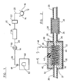
- Fig. 1 illustrates a plan view of a device according to the present invention; and
- Fig. 2 illustrates a cross-sectional detail view of certain of the elements shown in Fig. 1.
- The invention is shown in Figs. 1 and 2, wherein like elements in each of the figures are referenced by identical reference characters. Referring to Fig. 1, the
system 10 of the preferred embodiment comprises a nickel-hydrogen battery cell 12 having apositive electrode 14 and anegative electrode 16. The precise construction of the cell is not overly significant to the invention. Thecell 12 may be one that is generally known or may be of special construction. It should be appreciated that the only requirement is that the fuel for the cell is hydrogen, and any metal-hydrogen battery cell may use the teachings of this invention. For example, an exemplary cell could be made in accordance with the teaching of U.S. Patent No. 4,699,856. Alternatively, the cell may consist of a conventional Ni-KOH cell wherein KOH is used as the electrolyte, as is described in U.S. Patent No. 3,850,694. - The
cell 12 is in fluid communication with other elements of the system through a hermetically sealed piping means 20. The piping means 20 provides fluid communication throughout the complete system, connecting all of the elements in an in-line connection. The in-line connection defined by piping means 20 provides the path for transmission of gas through the system. In the preferred embodiment, the gas being transmitted is hydrogen and the piping means 20 is a singular, but linearly segmented, means for the transmission of the hydrogen. - Between each segment of the piping means 20 are disposed the discrete elements comprising the system. Taking each element in a linear progression starting with the
battery cell 12, anoptional heat exchanger 24 is provided to cool off the gaseous hydrogen which is being transmitted to thebattery cell 12 during a discharge step of the battery system. - The next element in the system, in-line with the piping means 20, is a
catalytic converter 24 for converting O2 molecules, in combination with hydrogen from the gaseous stream, into water. Stray oxygen molecules may find their way into the system, even if it is hermetically sealed, as a result of the electrolytic reaction which occurs in thebattery cell 12. - A
catalytic converter 24 is shown in cross-sectional detail in Fig. 2.Catalytic converter 24 comprises ahousing 26, which may be cylindrical, and acatalyst 28 in the form of thin strands of wire. The wire comprise one of several elements known to be good catalysts, such as platinum, palladium and nickel. Exemplary catalytic converters, such as oxygen removing purifiers, may be obtained from Matheson Gas Products Company in East Rutherford, New Jersey. - The
catalytic converter 24 is operational only during the recharging step of the battery system, when the gaseous hydrogen is transmitted from thebattery cell 12 through the piping means 20 for storage. Referring to Figs. 1 and 2, during recharging, the hydrogen gas is transmitted from the right toward the left. After passing through thecatalytic converter 24, the hydrogen stream should contain only H2 molecules and water vapor, H2O. The hydrogen stream is referred to as being "wet" and next passes throughdryer 30, which removes the water vapor from the hydrogen. - An appropriate drying means is illustrated in cross section in Fig. 2 and takes the form of a
molecular sieve dryer 30. Such a molecular sieve dryer is commercially available from the Linde Division of Union Carbide Corporation, Somerset, New Jersey. The Linde Model 4A molecular sieve, having a nominal pore diameter of 4A, has been found to work best in removing water from the hydrogen stream. - Referring to Fig. 2, an exemplary
molecular sieve dryer 30 comprises achamber 31 defined by achamber wall 32 having an internal layer of thermally insulatingmaterial 34. The thermal insulation is optional, but assists in avoiding loss of thermal energy during battery discharge. Thechamber 31 provides anopening 36 which, during battery recharging, introduces the "wet" hydrogen into thechamber 31, and a second opening 38, at an end opposite to opening 36, for expelling the "dry" hydrogen stream from thechamber 31 after it has passed through themolecular sieve 30. Theopenings 36,38 are, of course, hermetically sealed to the segments of piping means 20, enclosing and hermetically sealing thechamber 31 within thesystem 10 together with all of the other elements. -
Chamber 31 encloses the operational elements of the molecularmole sieve dryer 30, which elements comprise adsorbent 40 having precisely uniform sizes and dimensions, and which provide numerous minute passageways that permit passage of the H2 molecules but filter out the larger H2O molecules. The adsorbent 40 is usually a water adsorbing zeolite, of general formula M2/nO·Al2O3·xSiO2·yH2O where M is an appropriate cation of n valance and y is the number of adsorbed water molecules. For the Model 4A molecular sieve, Na12[(AlO2)12(SiO2)12]·27H2O provides good water adsorbing characteristics. - The adsorbent 40 is a static desiccant and can be packed in
chamber 31 in the form of powder, pellets, mesh or beads. The preferred embodiment includes beads with an impregnated saturation indicator mechanism, such as a view port covered by aclear window 42. Thewindow 42 may be made of glass and is sealed to thechamber wall 32. - The indicator comprises a chemical impregnated into the adsorbent 40. The adsorbent is in the form of beads to which the impregnated chemical imparts a blue color when the adsorbent 40 is fully activated by the removal of the water of hydration. When a gas stream is dried during passage through the
molecular sieve dryer 30, the blue color will turn pink as water is adsorbed. The pink color indicates the saturation point of the adsorbent 40, and in use with the present invention, denotes when thesystem 10 is operating properly during recharging of the battery. - During operational discharge of the
battery cell 12, the indicatingadsorbent 40 will turn from a pinkish to a bluish color. Conversely, during recharging of thebattery cell 12, the adsorbent 40 will turn from blue to pink as water is absorbed. Theport window 42 should be disposed within thechamber wall 32 to provide a clear and easy view of the indicatingadsorbent material 40 when the device is being monitored. - Disposed in a looping pattern within the adsorbent 40 is an electrical
resistance heating wire 44, comprising a known material such as nichrome. Theelectrical heating wire 44 is connected at both of its ends to a power source (not shown) through two electrically insulated leads 46. The power source may be thenickel hydride cell 12 during the discharging step, and theheating wire 44 may consume about 2.5-5.0% of the power ofcell 12. The layer of insulatingmaterial 34 is important in maintaining the heat provided bywire 44 within thechamber 31. Acontrol switch 48, which may be automatically or manually operated, is provided for introducing or shutting off electrical power to theresistance heating wire 44 when it is needed during the operation of thesystem 10. - The final segment of the piping means 20 extends to a
valve 49 and then to thehydrogen storage container 50, as shown in Fig. 1. Thecontainer 50 is a sealed chamber enclosing a porous bed of ametal hydride material 52 having a high capacity for hydrogen storage. Thevalve 49 may be a manually operated valve or a solenoid valve, and when closed, effectively seals thecontainer 50. Proper use ofvalve 49 operates to remove the unwanted, self discharge of the metal hydrogen battery cell, which has been a difficulty encountered in the past. - A significant feature of the present invention is providing a dry, oxygen-free hydrogen gas stream, which is obtained after the hydrogen passes through the
catalytic converter 24 and themolecular sieve dryer 30. The hydrogen stream, cleaned of impurities, is much less destructive of the metal hydride materials making up thehydride bed 52. As a consequence, it becomes possible to use inexpensive hydride materials which could otherwise not be usable. These hydride materials can supplant the very expensive, exotic, water-impermeable hydride materials in present use with hydride batteries. In the preferred embodiment according to the present invention, the use of LaNi5HX hydride material is contemplated. - In the past, application of these types of materials with hydride batteries caused water vapor in the hydrogen gas stream to be absorbed by the
hydride bed 52 instorage vessel 50 through a hydrogen/oxygen dissociation mechanism. When the hydrogen was again withdrawn for use during the discharge ofbattery cell 12, the oxygen atoms remained within the hydride material. Repeated cycles of discharging and recharging of the system eventually saturated the hydride material with oxygen to an extent that the hydride material no longer effectively absorbed hydrogen. Thus, the battery failed and would not function unless the hydride material was replaced by a fresh supply of hydride material. Under normal use parameters, the replacement of the hydride material was necessary after 10-20 cycles. The inventive device described above and illustrated in Figs. 1 and 2 leads to a vast improvement in the number of cycles that a hydride battery can perform effectively. - In battery operation, a complete cycle of the
system 10 both discharges and recharges thebattery cell 12. During discharge,battery cell 12 requires a source of electrons which provide electromotive force at thenegative electrode 16. The electrolytic reaction which occurs in thebattery cell 12 according to known processes requires a source of hydrogen molecules to drive the reaction toward producing the necessary electrons. - The electrolytic reaction is a reversible reaction, that is, the discharge step introduces hydrogen and produces a net result of electricity (electrons) and water as a by-product. The reaction can be driven in the reverse direction during recharging, where an external electric power source introduces electrons which are then used to produce H2 and OH- radicals from the available water. The reaction is well known for the case of nickel hydrogen, as is documented in technical treatises, such as the "Handbook of Batteries and Fuel Cells," ed. D. Linden, McGraw-Hill Book Co., New York, NY, ch.22, pp.22-2.
- Referring again to Fig. 1, hydrogen is introduced into the Ni-
KOH battery cell 12 by openingvalve 49.Valve 49 may be a solenoid valve which opens automatically when electrical power is needed from the battery. Thevalve 49 may contain the H2 under some low pressure, approximately 10-20 psi above atmospheric pressure which develops when the battery cell gives off hydrogen gas during the previous recharging step. During battery discharge, thenickel hydride cell 12 consumes hydrogen, and a hydrogen pressure differential develops between thehydrogen storage vessel 50 and thecell 12. This pressure differential tends to force a stream of gaseous hydrogen to flow toward thecell 12. - As the hydrogen in
cell 12 is consumed, the hydrogen partial pressure around thehydride bed 52 falls below the equilibrium pressure of the hydride material, and the hydride bed exudes more hydrogen into thevessel 50. It is well known in the hydride field that the equilibrium pressure may be predetermined by different initial parameters so that the hydride continues to give off hydrogen until a majority, approximately 80%, of the capacity of thenickel hydride cell 12 is depleted. Alternatively, heat may be provided to themetal hydride bed 52, which heat is available from an external source as waste heat or even may be generated by the nickelhydride battery cell 12 itself. Heating thehydride bed 52 will release H2 into thevessel 50 and through the piping means 20 to pass into the resistance-heatedmolecular sieve dryer 30. The heating of thehydride bed 52 may be used as an emergency fuel supply, such as a reserve amount of power necessary to travel to the next recharging point. - Referring now to Fig. 2, as the hydrogen stream diffuses through the
molecular sieve dryer 30, it encounters the water which was deposited on theadsorbent material 40 during a previous discharge step. The water evaporates to a certain extent into the hydrogen stream and is returned to thenickel hydride cell 12. - It has been found that during discharge, heating of the
chamber 31 by means of the electricalresistance heating wire 44 will evaporate the water more effectively and further activate the adsorbent 40 for water vapor adsorption during the next recharging step. If the adsorbent 40 is of the indicating type, discussed above, the change from a pink to blue color of the adsorbent 40 will be visible throughwindow port 42. - More importantly, the hydrogen stream becomes wet as the hydrogen is returned to the
battery cell 12. Return of the water vapor tobattery cell 12 provides moisture to the electrolyte in the cell in order to maintain the contact between the cell elements. As explained above, recharging of the battery cell tends to drive out the gaseous hydrogen which results from the reverse electrolytic reaction by developing hydrogen pressure in thebattery cell 12. A pressure differential builds up from the hydrogen in thecell 12, and gaseous hydrogen is forced out into the first segment of pipe means 20. However, water vapor which has evaporated into the hydrogen gas stream is also expelled from thebattery cell 12. Repeated recharging of thesystem 10 eventually tends to dry out the electrolyte incell 12. The cell then fails to provide any electric current because no contact is made by the elements within the cell. - One feature of this invention is that during recharging, the
electric heating wire 44 evaporates the residual water in the adsorbent 40 and the water vapor is then deposited within the electrolyte ofcell 12. Maintaining the moisture of the cell elements provides a more efficient operation of the cell during discharge and is an improvement over prior art devices. - It should be noted that during the discharge step the
catalytic converter 24 is not operating. The hydrogen stream continues to travel through the in-line pipe means 20 to theheat exchanger 22, shown in Fig. 1. Theheat exchanger 22 is an optional element which may be used to cool the hydrogen. It has been found that cooling the hydrogen tends to produce the temperature of the hydrogen stream to ambient temperatures. Cooling the hydrogen stream is desirable for driving the electrolytic reaction in thebattery cell 12 during discharge. Entrance of the cool hydrogen into thecell 12 drives the electrolytic reaction which produces a potential across theelectrodes - A circuit connection to an electrical load across the
electrodes cell 12, which current production continues conversion of the hydrogen to water. The drop in the hydrogen pressure in thecell 12 causes a pressure differential which tends to push more hydrogen from thehydrogen storage vessel 50 into the in-line stream and through the pipe means 20 to thebattery cell 12. The reaction proceeds and the hydrogen continues to flow as long as electrical current is consumed by the circuit and load (not shown). - To stop the reaction, the circuit through the
electrodes cell 12 and thehydrogen storage vessel 50 develops. With a constant pressure, there is also an equilibrium point which develops between themetal hydride bed 52 and the hydrogen in thevessel 50. Thus, all of the various components remain at equilibrium and the system remains static with no hydrogen flow between the elements. - A similar result may be reached by shutting off of the
optional valve 49, which will also cut off the hydrogen flow and isolate the two separate reversible reactions, that of the electrolytic reaction in thecell 12 and of the hydrogen desorption reaction from thehydride bed 52 in thevessel 50. One advantage of ashutoff valve 49 is that the operation ofsystem 10 may be stopped immediately in case of emergency, such as if a hydrogen leak develops. Also, as described above, ashutoff valve 49 removes problems which may otherwise develop due to the unwanted self discharge of thebattery cell 12. - During the recharging step, the reversible reactions which take place within
system 10 are driven in the opposite direction from the discharge step. The recharge step first requires a source of steady electric power. Such a source may be a power grid, such as is generally available. Another possible source is regular stations for recharging batteries which are utilized in an automobile. It is contemplated that an automobile which operates on a large battery made according to the present invention may be able to recharge while on the road at a station which provides a recharging service. - It is also contemplated that the source of electric power may be a solar panel which may provide electric power to a first battery during daylight hours. A photovoltaic system is capable of charging a primary metal hydride battery cell and storing the hydrogen gas evolved from the reverse electrolytic reaction in an identical manner to that of a conventional recharge system. A user may utilize the automobile with a first battery during one day, and an alternate battery may be utilized on a subsequent day while the first battery is recharging.
- Referring again to Fig. 1, recharging of the
system 10 begins by introducing electrons to thenegative electrode 16, in effect making it a positive electrode and thus reversing the electrolytic reaction described above. The reverse reaction results in the conversion of the water, left in thecell 12 as a by-product, into hydrogen and hydroxyl ions (OH-). The hydroxyl ions remain in solution, and are the negatively charged half of the KOH salt which was originally an element of the battery cell. - The hydrogen forms H2 molecules which collects in
cell 12 as a gas. Continued collection of the hydrogen increases the hydrogen gas pressure and impels the hydrogen into the first segment of the piping means 20. The hydrogen gas is not affected by theheat exchanger 22 as it travels in a stream through theheat exchanger 22, because theheat exchanger 22 is not operated during the recharging cycle. - The hydrogen stream continues to flow through the
system 10, from right to left in Figs. 1 and 2, and reaches thecatalytic converter 24. The hydrogen stream at this point may include oxygen molecules which can appear in the system as trace impurities from the electrolytic reaction. For example, two OH- ions may join to obtain O2. These trace amounts of O2 cause deterioration of themetal hydride bed 52 after repeated cycles if the oxygen is permitted to reach the hydride material. Continued use of the system without oxygen removal results in excessive oxygen deterioration of the metal hydride material inbed 52. - The
catalytic converter 24 converts all of the O2 molecules by combining with hydrogen from the passing hydrogen stream to form water molecules, H2O. The water evaporates into the H2 stream and is borne along as water vapor within the stream. - The hydrogen in the in-line pipe means 20 is wet before reaching the
dryer 30, as is explained above. Themolecular sieve dryer 30, in a cool state because theresistance heating wire 44 is not operating, dries out the hydrogen stream, removing the water vapor by adsorbing the water molecules within the zeolite material, as explained above. - The dry hydrogen stream then continues through the pipe means 20 and into the
hydrogen storage vessel 50. As the hydrogen builds up pressure in thestorage vessel 50, the equilibrium of the hydriding process in thehydride bed 52 is altered. That is, as the pressure builds up, the metal hydride bed absorbs more hydrogen because the hydrogen pressure in thevessel 50 exceeds the equilibrium pressure of the hydriding process. As thehydride bed 52 absorbs the hydrogen, the hydrogen pressure in thevessel 50 becomes lower than the hydrogen pressure in thecell 12, which is continuing to produce H2 molecules as a result of the reverse electrolytic reaction. That difference in the hydrogen pressure develops a pressure differential and results in the stream of hydrogen gas which is transmitted from thecell 12 by the pipe means 20 through thecatalytic converter 24 and thedryer 30 into thevessel 50. - The stream of gaseous hydrogen will continue until the
battery cell 12 is completely recharged. The completion of the recharge cycle can be sensed and indicated by a known mechanism, such as when the potential or power available in thecell 12 reaches a certain level. When recharging is completed, the electrical power source (not shown) is removed from thebattery cell 12, and all elements of thesystem 10 are allowed to return to equilibrium. As an additional safety feature, thevalve 49 may also be shut down, thus isolating the hydrogen stored inbed 52 from the remainder of thesystem 10. - When the
valve 49 is shut, the hydrogen pressure in thevessel 50 reaches an equilibrium pressure with the hydriding process in thebed 52. Under normal conditions, this equilibrium pressure should be at or near the final hydrogen pressure of thesystem 10 just before thevalve 49 is closed. Closing of thevalve 49 stores the energy in the metal hydride within thesystem 10. - The hydrogen pressure in the remainder of the
system 10 then reaches an equilibrium in thebattery cell 12 in accordance with the electrolytic reaction set forth above. It should be noted, however, that the potential across theelectrodes battery cell 12 does not comprise a part of an electrical circuit. If thebattery cell 12 is not immediately utilized, maintaining the potential across theelectrodes cell 12 and pipe means 20 is dissipated. Proper design of thesystem 10 will minimize the volume of hydrogen available in this space. When the gaseous hydrogen is completely dissipated in the electolytic reaction, the hydrogen pressure in thecell 12 falls to a level at or near atmospheric pressure but, in any case, less than the hydrogen pressure in thehydrogen storage vessel 50. Thesystem 10 is now ready for use. - It should be noted that during the period when the hydrogen is stored in
vessel 50, thebattery cell 12 is not in operation and there is no potential across theelectrodes battery system 10 thus increases the sheft life of thebattery cell 12 for an indefinite amount of time, and thesystem 10 remains as ready for use months or years after it has been charged as it is immediately after it has been recharged. Moreover, the inventive system may undergo a much greater number of cycles because thehydride bed 52 is protected from oxygen which destroys the ability of the metal hydride material to retain and store large amounts of hydrogen. - A full appreciation of the invention can lead one skilled in the art to modification or adaptation of the invention following the general principle of an in-line, segmented, hydride battery/hydrogen storage vessel in which the hydrogen stream is purified of oxygen atoms. For example, one possible modification may be to dispose the
catalytic converter 24 and themolecular sieve dryer 30 within a chamber which also encloses the nickel-hydrogen cell 12. Such an integral system may be appropriate for mass production of thesystem 10 in a design which permits thesystem 10 to be easily disposed in an electric automobile. For example, thehydrogen storage vessel 50 may be removably connected to the pipe means 20. When thehydride bed 52 deteriorates to a nonoperational condition, anew vessel 50 may be exchanged for the old one. - Alternatively, the
catalytic converter 24, andmolecular sieve 30 may be disposed in a chamber (not shown) withinvessel 50 which is isolated from thehydride bed 52. This type ofintegral storage vessel 50 may be removed and replaced by a new one, while thehydride bed 52, themolecular sieve dryer 30 and thecatalytic converter 24 are all reconditioned for recycled use. - The invention has been described in connection with a preferred form of the invention. It will be understood that any modification may be made thereto while retaining the general scope of the invention, which is only limited by the following claims.
Claims (8)
- A battery system utilizing a stream of hydrogen for generating electrical power on demand, comprising:a hydrogen storage vessel having at least one opening and a metal hydride bed disposed therein, the metal hydride bed being able to absorb hydrogen under certain conditions and to release hydrogen under other conditions;at least one battery cell enclosed within a vessel, each said battery cell comprising an electrolyte and an oxidant, the enclosure of the battery cell having at least one opening;in-line piping means having at least two ends, one end being sealingly connected to said hydrogen storage vessel opening and the other end being sealingly connected to the battery cell opening;a predetermined quantity of hydrogen which is disposed within said system, whereby during discharging of the battery cell, the hydrogen is impelled to flow in a stream from said hydrogen storage vessel to said battery cell and during recharging of the battery cell, the hydrogen stream is impelled to flow from said battery cell to said hydrogen storage vessel;a catalytic converter disposed in line between the battery cell and the hydride bed; anda molecular sieve dryer having a water adsorbing material for adsorbing water vapor from the stream of hydrogen during battery recharging and for releasing water as a vapor into the hydrogen stream during battery discharge, the molecular sieve dryer being disposed in line between said catalytic converter and said metal hydride bed.
- The battery system according to claim 1 wherein said molecular sieve dryer further comprises zeolite beads as a water adsorbing material.
- The battery system according to claim 1 wherein said molecular sieve dryer further comprises a resistance heating wire disposed within said water adsorbing material, said wire for heating said water adsorbing material when an electrical current is passed through said wire for evaporating water which is adsorbed in said water adsorbing material, whereby the water is released into the hydrogen stream during discharge of the battery.
- The battery system according to claim 1 wherein a valve is disposed in-line in the piping means for shutting off the stream of hydrogen.
- The battery system according to claim 1 wherein said molecular sieve dryer further comprises a sealed view port affording a view of said adsorbent material, said adsorbent material including an impregnated indicating chemical which causes the adsorbent material to indicate a condition of water saturation.
- The battery system according to claim 1 wherein said hydrogen storage vessel includes a means for heating said metal hydride bed and for selectively raising the temperature of said bed whereby release of a reserve amount of hydrogen is obtained.
- A method of repeatedly utilizing a stream of hydrogen for generating electrical power on demand, the method comprising the steps of:a) providing a sealed hydrogen system including a segmented metal-hydrogen battery cell, a catalytic converter, a molecular sieve dryer, a metal hydride storage vessel and in-line piping means between at least the metal hydride storage vessel and a container for the metal-hydrogen cell, the catalytic converter and the molecular sieve dryer both being disposed between the metal hydride bed, contained in said storage vessel, and the battery cell, in said container;b) selectively releasing hydrogen gas from said hydride bed and piping said hydrogen gas through said in-line piping means, said catalytic converter and said molecular sieve dryer to said battery cell;c) utilizing electrical power emanating from said battery cell, said battery cell producing electrical power by consuming said hydrogen gas;d) recharging the battery cell by providing an external source of electrical power to said battery cell, whereby recharging of the battery cell forms hydrogen gas;e) piping said hydrogen gas through said catalytic converter and thereby catalytically converting any oxygen impurities into water;f) piping said hydrogen gas through said molecular sieve dryer, thereby removing any water vapor from said hydrogen gas;g) piping said hydrogen gas to said metal hydride bed and storing said hydrogen gas in said metal hydride bed; andh) repeating steps a)-g) as desired.
- The method according to claim 7, above, wherein step b) further comprises heating an adsorbent material in said molecular sieve dryer, thereby releasing water vapor into the hydrogen gas being piped therethrough.
Applications Claiming Priority (3)
| Application Number | Priority Date | Filing Date | Title |
|---|---|---|---|
| US978815 | 1992-11-19 | ||
| US07/978,815 US5250368A (en) | 1992-11-19 | 1992-11-19 | Extended cycle-life metal hydride battery for electric vehicles |
| PCT/US1993/010625 WO1994011914A1 (en) | 1992-11-19 | 1993-11-05 | Extended cycle-life metal hydride battery for electric vehicles |
Publications (3)
| Publication Number | Publication Date |
|---|---|
| EP0669042A1 EP0669042A1 (en) | 1995-08-30 |
| EP0669042A4 EP0669042A4 (en) | 1996-04-17 |
| EP0669042B1 true EP0669042B1 (en) | 1997-08-13 |
Family
ID=25526414
Family Applications (1)
| Application Number | Title | Priority Date | Filing Date |
|---|---|---|---|
| EP94900539A Expired - Lifetime EP0669042B1 (en) | 1992-11-19 | 1993-11-05 | Extended cycle-life metal hydride battery for electric vehicles |
Country Status (7)
| Country | Link |
|---|---|
| US (1) | US5250368A (en) |
| EP (1) | EP0669042B1 (en) |
| JP (1) | JP2745162B2 (en) |
| AU (1) | AU5548994A (en) |
| CA (1) | CA2148221C (en) |
| DE (1) | DE69313130T2 (en) |
| WO (1) | WO1994011914A1 (en) |
Cited By (2)
| Publication number | Priority date | Publication date | Assignee | Title |
|---|---|---|---|---|
| DE19902219C1 (en) * | 1999-01-21 | 2000-06-08 | Daimler Chrysler Ag | Process for operating a fuel cell system comprises removing moisture from a waste air stream of a fuel cell, desorbing the water and recycling |
| DE19918849A1 (en) * | 1999-04-19 | 2000-10-26 | Mannesmann Ag | Appliance and method for moistening fuel cell membranes and suitable fuel cell |
Families Citing this family (30)
| Publication number | Priority date | Publication date | Assignee | Title |
|---|---|---|---|---|
| US5599638A (en) | 1993-10-12 | 1997-02-04 | California Institute Of Technology | Aqueous liquid feed organic fuel cell using solid polymer electrolyte membrane |
| US5773162A (en) * | 1993-10-12 | 1998-06-30 | California Institute Of Technology | Direct methanol feed fuel cell and system |
| US6703150B2 (en) | 1993-10-12 | 2004-03-09 | California Institute Of Technology | Direct methanol feed fuel cell and system |
| US5419981A (en) * | 1993-11-01 | 1995-05-30 | Ergenics, Inc. | Hydrogen electrochemical cell housing |
| US5510202A (en) * | 1994-02-24 | 1996-04-23 | Rockwell International Corporation | Quasi-passive variable pressure regenerative fuel cell system |
| US5506066A (en) * | 1994-03-14 | 1996-04-09 | Rockwell International Corporation | Ultra-passive variable pressure regenerative fuel cell system |
| US5532074A (en) * | 1994-06-27 | 1996-07-02 | Ergenics, Inc. | Segmented hydride battery |
| US5688611A (en) * | 1994-06-27 | 1997-11-18 | Ergenics, Inc. | Segmented hydride battery including an improved hydrogen storage means |
| US5673939A (en) | 1995-09-20 | 1997-10-07 | The Babcock & Wilcox Company | Fuel tank for storing and dispensing hydrogen and oxygen gas to a fuel cell |
| US5658013A (en) * | 1995-09-20 | 1997-08-19 | The Babcock & Wilcox Company | Fuel tank for vehicles for holding and dispensing both a liquid and gaseous fuel therein |
| JP3583857B2 (en) * | 1996-03-26 | 2004-11-04 | 三洋電機株式会社 | Hydrogen storage utilization equipment |
| EP0813264A3 (en) * | 1996-06-14 | 2004-02-25 | Matsushita Electric Industrial Co., Ltd. | Fuel cell system, fuel feed system for fuel cell and portable electric appliance |
| US5900330A (en) * | 1997-09-25 | 1999-05-04 | Kagatani; Takeo | Power device |
| US6042960A (en) * | 1997-10-15 | 2000-03-28 | Ergenics, Inc. | Automatic water vapor density control of hydrogen gas |
| US6485852B1 (en) * | 2000-01-07 | 2002-11-26 | Delphi Technologies, Inc. | Integrated fuel reformation and thermal management system for solid oxide fuel cell systems |
| US6508866B1 (en) | 2000-07-19 | 2003-01-21 | Ergenics, Inc. | Passive purification in metal hydride storage apparatus |
| JP2005506658A (en) * | 2001-10-09 | 2005-03-03 | エレクトラスター,エルエルシー | NiMH battery |
| US7254983B2 (en) * | 2001-10-16 | 2007-08-14 | Hera Usa Inc. | Fuel gauge for hydrogen storage media |
| US7169489B2 (en) | 2002-03-15 | 2007-01-30 | Fuelsell Technologies, Inc. | Hydrogen storage, distribution, and recovery system |
| US20030234010A1 (en) * | 2002-06-25 | 2003-12-25 | Redmond Scott D. | Methods and apparatus for converting internal combustion engine (ICE) vehicles to hydrogen fuel |
| US7011768B2 (en) | 2002-07-10 | 2006-03-14 | Fuelsell Technologies, Inc. | Methods for hydrogen storage using doped alanate compositions |
| US20040065171A1 (en) | 2002-10-02 | 2004-04-08 | Hearley Andrew K. | Soild-state hydrogen storage systems |
| US6951111B2 (en) * | 2003-10-06 | 2005-10-04 | Chentek, Llc | Combusting hydrocarbons excluding nitrogen using mixed conductor and metal hydride compressor |
| US20050229489A1 (en) * | 2004-04-19 | 2005-10-20 | Texaco Inc. | Apparatus and method for hydrogen generation |
| US7318520B2 (en) * | 2004-09-27 | 2008-01-15 | Ergenics Corp. | Flexible and semi-permeable means of hydrogen delivery in storage and recovery systems |
| US20060065553A1 (en) * | 2004-09-27 | 2006-03-30 | Golben P M | Flexible hydrogen delivery mechanism for storage and recovery of hydrogen |
| DE102010028861A1 (en) * | 2010-05-11 | 2011-11-17 | Sb Limotive Company Ltd. | Drying device for reducing the humidity of a gas, housing, method for producing the housing, battery and motor vehicle |
| FR3010401B1 (en) | 2013-09-06 | 2015-09-25 | Commissariat Energie Atomique | REGENERATING A TRAP FOR IMPURITIES IN HYDROGEN USING HEAT OUT OF A HYDRIDE RESERVOIR |
| DE102019217116A1 (en) * | 2019-11-06 | 2021-05-06 | Siemens Aktiengesellschaft | Power-to-X system with optimized hydrogen drying and cleaning |
| DE102019217114A1 (en) * | 2019-11-06 | 2021-05-06 | Siemens Energy Global GmbH & Co. KG | Power-to-X system with optimized hydrogen drying and cleaning |
Family Cites Families (7)
| Publication number | Priority date | Publication date | Assignee | Title |
|---|---|---|---|---|
| CH468727A (en) * | 1967-02-07 | 1969-02-15 | Battelle Memorial Inst Interna | Electric accumulator |
| US3850694A (en) * | 1972-11-27 | 1974-11-26 | Communications Satellite Corp | Low pressure nickel hydrogen cell |
| US4343868A (en) * | 1980-12-31 | 1982-08-10 | Electric Power Research Institute, Inc. | Hydrogen ion-producing cell and technique for controlling the pH of battery electrolytes |
| NL8601674A (en) * | 1986-06-26 | 1988-01-18 | Philips Nv | ELECTROCHEMICAL CELL. |
| US4692390A (en) * | 1986-08-18 | 1987-09-08 | General Electric Company | Method and system for hydrogen thermal-electrochemical conversion |
| US5047301A (en) * | 1989-03-31 | 1991-09-10 | Ergenics Power Systems, Inc. | High temperature battery and system utilizing same |
| NL8901776A (en) * | 1989-07-11 | 1991-02-01 | Philips Nv | ELECTROCHEMICAL CELL. |
-
1992
- 1992-11-19 US US07/978,815 patent/US5250368A/en not_active Expired - Lifetime
-
1993
- 1993-11-05 CA CA002148221A patent/CA2148221C/en not_active Expired - Fee Related
- 1993-11-05 WO PCT/US1993/010625 patent/WO1994011914A1/en not_active Ceased
- 1993-11-05 AU AU55489/94A patent/AU5548994A/en not_active Abandoned
- 1993-11-05 EP EP94900539A patent/EP0669042B1/en not_active Expired - Lifetime
- 1993-11-05 DE DE69313130T patent/DE69313130T2/en not_active Expired - Lifetime
- 1993-11-05 JP JP6512210A patent/JP2745162B2/en not_active Expired - Fee Related
Cited By (3)
| Publication number | Priority date | Publication date | Assignee | Title |
|---|---|---|---|---|
| DE19902219C1 (en) * | 1999-01-21 | 2000-06-08 | Daimler Chrysler Ag | Process for operating a fuel cell system comprises removing moisture from a waste air stream of a fuel cell, desorbing the water and recycling |
| DE19918849A1 (en) * | 1999-04-19 | 2000-10-26 | Mannesmann Ag | Appliance and method for moistening fuel cell membranes and suitable fuel cell |
| DE19918849C2 (en) * | 1999-04-19 | 2003-04-30 | Mannesmann Ag | Device for moistening a fuel cell membrane and its use |
Also Published As
| Publication number | Publication date |
|---|---|
| CA2148221C (en) | 2004-11-02 |
| DE69313130D1 (en) | 1997-09-18 |
| CA2148221A1 (en) | 1994-05-26 |
| JPH08503102A (en) | 1996-04-02 |
| DE69313130T2 (en) | 1998-02-26 |
| US5250368A (en) | 1993-10-05 |
| EP0669042A1 (en) | 1995-08-30 |
| EP0669042A4 (en) | 1996-04-17 |
| AU5548994A (en) | 1994-06-08 |
| WO1994011914A1 (en) | 1994-05-26 |
| JP2745162B2 (en) | 1998-04-28 |
Similar Documents
| Publication | Publication Date | Title |
|---|---|---|
| EP0669042B1 (en) | Extended cycle-life metal hydride battery for electric vehicles | |
| US5532074A (en) | Segmented hydride battery | |
| CN101341562A (en) | Supercapacitor pressure control system | |
| US5688611A (en) | Segmented hydride battery including an improved hydrogen storage means | |
| US7226675B2 (en) | Very low emission hybrid electric vehicle incorporating an integrated propulsion system including a fuel cell and a high power nickel metal hydride battery pack | |
| US3850694A (en) | Low pressure nickel hydrogen cell | |
| EP1372818B1 (en) | Fuel cell system having a replaceable getter element for purifying the fuel supply | |
| JP5515028B2 (en) | Reversible fuel cell and reversible fuel cell module | |
| US6524534B1 (en) | Apparatus for removing flammable gas | |
| EP1469544A1 (en) | Method of operating a fuel cell, air purifying apparatus and fuel cell | |
| KR102409387B1 (en) | Metal air battery and operation method of the metal air battery | |
| JP2002358992A (en) | Fuel cell power generation system | |
| US6042960A (en) | Automatic water vapor density control of hydrogen gas | |
| US5264301A (en) | Metal oxide-hydrogen battery incorporating a mechanism for maintaining a constant pressure in the battery | |
| JP6904611B2 (en) | Rechargeable electrochemical device for generating electrical energy | |
| KR101015698B1 (en) | Powdered fuel cell | |
| JPS6249703B2 (en) | ||
| JP4010152B2 (en) | High-pressure hydrogen production apparatus and production method thereof | |
| US6042964A (en) | Thermally regenerative battery with intercalatable electrodes and selective heating means | |
| WO1984002283A1 (en) | Means and procedure for removal of carbon dioxide | |
| JP3433975B2 (en) | High temperature solid electrolyte fuel cell | |
| JP2004103277A (en) | Fuel cell system | |
| US3964928A (en) | Lead-oxygen DC power supply system having a closed loop oxygen and water system | |
| Herbert | Battery Research and Fuel Cells | |
| RU197097U1 (en) | Hydrogen trap based on a battery of open-type nickel-hydrogen batteries |
Legal Events
| Date | Code | Title | Description |
|---|---|---|---|
| PUAI | Public reference made under article 153(3) epc to a published international application that has entered the european phase |
Free format text: ORIGINAL CODE: 0009012 |
|
| 17P | Request for examination filed |
Effective date: 19950613 |
|
| AK | Designated contracting states |
Kind code of ref document: A1 Designated state(s): DE FR GB IT SE |
|
| A4 | Supplementary search report drawn up and despatched |
Effective date: 19960229 |
|
| AK | Designated contracting states |
Kind code of ref document: A4 Designated state(s): DE FR GB IT SE |
|
| GRAG | Despatch of communication of intention to grant |
Free format text: ORIGINAL CODE: EPIDOS AGRA |
|
| 17Q | First examination report despatched |
Effective date: 19961107 |
|
| GRAH | Despatch of communication of intention to grant a patent |
Free format text: ORIGINAL CODE: EPIDOS IGRA |
|
| GRAH | Despatch of communication of intention to grant a patent |
Free format text: ORIGINAL CODE: EPIDOS IGRA |
|
| GRAA | (expected) grant |
Free format text: ORIGINAL CODE: 0009210 |
|
| AK | Designated contracting states |
Kind code of ref document: B1 Designated state(s): DE FR GB IT SE |
|
| REF | Corresponds to: |
Ref document number: 69313130 Country of ref document: DE Date of ref document: 19970918 |
|
| ET | Fr: translation filed | ||
| PLBE | No opposition filed within time limit |
Free format text: ORIGINAL CODE: 0009261 |
|
| STAA | Information on the status of an ep patent application or granted ep patent |
Free format text: STATUS: NO OPPOSITION FILED WITHIN TIME LIMIT |
|
| 26N | No opposition filed | ||
| REG | Reference to a national code |
Ref country code: GB Ref legal event code: IF02 |
|
| REG | Reference to a national code |
Ref country code: GB Ref legal event code: 732E |
|
| REG | Reference to a national code |
Ref country code: FR Ref legal event code: TP |
|
| PGFP | Annual fee paid to national office [announced via postgrant information from national office to epo] |
Ref country code: DE Payment date: 20120531 Year of fee payment: 19 |
|
| PGFP | Annual fee paid to national office [announced via postgrant information from national office to epo] |
Ref country code: GB Payment date: 20120501 Year of fee payment: 19 Ref country code: FR Payment date: 20120608 Year of fee payment: 19 Ref country code: SE Payment date: 20120502 Year of fee payment: 19 |
|
| PGFP | Annual fee paid to national office [announced via postgrant information from national office to epo] |
Ref country code: IT Payment date: 20120507 Year of fee payment: 19 |
|
| GBPC | Gb: european patent ceased through non-payment of renewal fee |
Effective date: 20121105 |
|
| PG25 | Lapsed in a contracting state [announced via postgrant information from national office to epo] |
Ref country code: SE Free format text: LAPSE BECAUSE OF NON-PAYMENT OF DUE FEES Effective date: 20121106 |
|
| REG | Reference to a national code |
Ref country code: FR Ref legal event code: ST Effective date: 20130731 |
|
| PG25 | Lapsed in a contracting state [announced via postgrant information from national office to epo] |
Ref country code: IT Free format text: LAPSE BECAUSE OF NON-PAYMENT OF DUE FEES Effective date: 20121105 |
|
| REG | Reference to a national code |
Ref country code: DE Ref legal event code: R119 Ref document number: 69313130 Country of ref document: DE Effective date: 20130601 |
|
| PG25 | Lapsed in a contracting state [announced via postgrant information from national office to epo] |
Ref country code: DE Free format text: LAPSE BECAUSE OF NON-PAYMENT OF DUE FEES Effective date: 20130601 |
|
| PG25 | Lapsed in a contracting state [announced via postgrant information from national office to epo] |
Ref country code: GB Free format text: LAPSE BECAUSE OF NON-PAYMENT OF DUE FEES Effective date: 20121105 Ref country code: FR Free format text: LAPSE BECAUSE OF NON-PAYMENT OF DUE FEES Effective date: 20121130 |