EP0667564A2 - Electrophotographic imaging with toners of opposite sign electrical charge - Google Patents
Electrophotographic imaging with toners of opposite sign electrical charge Download PDFInfo
- Publication number
- EP0667564A2 EP0667564A2 EP94114619A EP94114619A EP0667564A2 EP 0667564 A2 EP0667564 A2 EP 0667564A2 EP 94114619 A EP94114619 A EP 94114619A EP 94114619 A EP94114619 A EP 94114619A EP 0667564 A2 EP0667564 A2 EP 0667564A2
- Authority
- EP
- European Patent Office
- Prior art keywords
- toner
- photoconductive surface
- charge potential
- charge
- image
- Prior art date
- Legal status (The legal status is an assumption and is not a legal conclusion. Google has not performed a legal analysis and makes no representation as to the accuracy of the status listed.)
- Granted
Links
- 238000003384 imaging method Methods 0.000 title claims description 11
- 238000000034 method Methods 0.000 claims abstract description 47
- 238000007600 charging Methods 0.000 claims description 11
- 238000007599 discharging Methods 0.000 claims description 10
- 230000001747 exhibiting effect Effects 0.000 claims description 4
- 239000002245 particle Substances 0.000 description 7
- 239000000049 pigment Substances 0.000 description 7
- 238000007786 electrostatic charging Methods 0.000 description 6
- 239000000463 material Substances 0.000 description 5
- 239000000872 buffer Substances 0.000 description 4
- 239000010410 layer Substances 0.000 description 3
- 239000000203 mixture Substances 0.000 description 3
- 239000003795 chemical substances by application Substances 0.000 description 2
- 239000003086 colorant Substances 0.000 description 2
- 238000009472 formulation Methods 0.000 description 2
- 239000000654 additive Substances 0.000 description 1
- 239000012790 adhesive layer Substances 0.000 description 1
- 239000002131 composite material Substances 0.000 description 1
- 230000001143 conditioned effect Effects 0.000 description 1
- 230000003750 conditioning effect Effects 0.000 description 1
- 239000004020 conductor Substances 0.000 description 1
- 238000000151 deposition Methods 0.000 description 1
- 238000010586 diagram Methods 0.000 description 1
- 230000008030 elimination Effects 0.000 description 1
- 238000003379 elimination reaction Methods 0.000 description 1
- 230000007613 environmental effect Effects 0.000 description 1
- 230000003993 interaction Effects 0.000 description 1
- 238000004519 manufacturing process Methods 0.000 description 1
- 239000011159 matrix material Substances 0.000 description 1
- 238000012986 modification Methods 0.000 description 1
- 230000004048 modification Effects 0.000 description 1
- 229920005989 resin Polymers 0.000 description 1
- 239000011347 resin Substances 0.000 description 1
- 230000000087 stabilizing effect Effects 0.000 description 1
Images


Classifications
-
- G—PHYSICS
- G03—PHOTOGRAPHY; CINEMATOGRAPHY; ANALOGOUS TECHNIQUES USING WAVES OTHER THAN OPTICAL WAVES; ELECTROGRAPHY; HOLOGRAPHY
- G03G—ELECTROGRAPHY; ELECTROPHOTOGRAPHY; MAGNETOGRAPHY
- G03G13/00—Electrographic processes using a charge pattern
- G03G13/01—Electrographic processes using a charge pattern for multicoloured copies
-
- G—PHYSICS
- G03—PHOTOGRAPHY; CINEMATOGRAPHY; ANALOGOUS TECHNIQUES USING WAVES OTHER THAN OPTICAL WAVES; ELECTROGRAPHY; HOLOGRAPHY
- G03G—ELECTROGRAPHY; ELECTROPHOTOGRAPHY; MAGNETOGRAPHY
- G03G15/00—Apparatus for electrographic processes using a charge pattern
- G03G15/01—Apparatus for electrographic processes using a charge pattern for producing multicoloured copies
- G03G15/0105—Details of unit
- G03G15/0126—Details of unit using a solid developer
Definitions
- the present invention relates generally to the following U.S. patent application being assigned to the same assignee, entitled:
- the present invention relates generally to electrophotographic imaging system, more particularly, to the elimination of the restriction that all toners be capable of charging to the same sign of electrical charge.
- a photoconductive surface in an electrophotographic imaging system is first charged to a uniform potential and then is "exposed" to an image to be reproduced by the scanning of a laser beam thereacross.
- the photoconductor thereby obtains an electrostatic latent image that constitutes a matrix of discharged pixels on the photoconductor's surface.
- the photoconductive surface is generally developed using a black toner that adheres to the discharged pixel areas to form the image. Thereafter, the toned photoconductive surface is then carried to a transfer station where the image is transferred to a media sheet.
- a multi-color printer successive images are developed employing different color toners supplied from corresponding toner modules. Color printing is normally done with yellow, cyan and magenta toners that are applied, in registration, during successive rotations of the photoconductive surface.
- the printer also generally includes a toner module with black toner.
- the developed color image is then transferred from the photoconductive surface to a media sheet.
- an alternative method to that described above is to use an intermediate medium wherein the individual color planes are transferred from the photoconductive surface to the intermediate medium. Once all the color planes have been transferred to the intermediate media, the composite image is transferred to the final media sheet. Heat is usually applied to permanently fuse the image to the media sheet in order to form a completed multi-color print.
- the electrophotographic process is based on the electrostatic attraction of charged toner particles for opposite (or relatively opposite) sign charge on a photoconductor material on which an image has been formed.
- the surface of the photoconductor may be positive relative to the negative charge on the toner particles, or vice versa.
- the desired image is developed on the photoconductor (often an organic photoconductor, OPC) using the customary principles of discharge area development (DAD).
- DAD discharge area development
- the OPC must be capable of charging to the same sign of electrical potential as the formal charge on the toner.
- the toner when the OPC charges positively, the toner must have a positive charge.
- the concept also works when the OPC and toner are both negatively charged. DAD is preferred because the printed dots are oval or elliptical, which gives better print quality in terms of edge smoothness of the printed images.
- the entire surface of the OPC is charged up to a certain potential, the laser discharges those areas to be imaged ("write black"), and toner particles, having the same sign charge as the still-charged area of the OPC, are brought into contact with the OPC.
- the toner particles are electrostatically repelled by the same-sign charged areas and attracted to the discharged image area.
- the toner is electrostatically deposited onto the OPC. If the toners are transparent enough to the laser light, this process can be repeated until as many color planes as desired are overlaid.
- a toner may be used which has an opposite sign charge to the photoconductor material and results in charge area development (CAD).
- CAD charge area development
- the laser must discharge the area that is NOT intended to receive the toner (write white).
- the toner which is of opposite sign compared to charged imaged areas, is electrostatically repelled by the discharged area and attracted to the opposite-sign charged areas. This mode is less favored because the dots formed by the toner are the "inverse" of the laser image and consequently have points or cupped edges. Thus, image edges formed by these pointed spots will be rougher and print quality is negatively impacted.
- an imaging system incorporating the invention that includes a movable photoconductive surface, and an electrostatic system for repetitively charging the photoconductive surface to a first charge potential. Selective areas of the photoconductive surface are discharged to a second charge potential in accordance with image signals. A first toner exhibiting a charge state that is attracted by the second charge potential and is repelled by the first charge potential. There is also a second toner exhibiting an opposite charge state to the first toner. The second toner is attracted by the first charge potential and is repelled by the second charge potential.
- a controller causes the first toner to be applied to the imaged photoconductive surface and the entire photoconductive surface is recharged. Thereafter, non-imaged areas of the photoconductive surface are discharged to a charge potential that repels the second toner. The second toner is applied to imaged areas that remain at the first charge potential.
- a color electrophotography system 10 comprises a drum 12 that is coated, in the known manner, with a photoconductive surface 14. While a drum 12 is shown, those skilled in the art will realize that any continuous photoconductive surface 14 may be employed with this invention.
- An electrostatic charging station 16 charges photoconductive surface 14 as it passes therebeneath.
- a laser 18 subsequently exposes selected areas of pre-charged photoconductive surface 14 to create image areas that exhibit a different charge level.
- photoconductive surface 14 must be capable of charging to the same sign of electrical potential as charges on a toner to be subsequently used for development. For example, when photoconductive surface 14 is charged by electrostatic charging station 16 to a positive potential, the color toner must also have a positive charge.
- the invention may also be implemented when photoconductive surface 14 is pre-charged to a negative potential and the toner is negatively charged.
- laser 18 discharges selected areas on photoconductive surface 14.
- electrostatic charging station 16 causes photoconductive surface 14 to have a high positive potential
- laser 18 acts to discharge photoconductive surface 14 to a more negative potential. It is to be understood that the potential values to be hereafter described are relative to each other and not with respect to any absolute value or measure.
- photoconductive surface 14 is shown after having been charged to a high positive potential by electrostatic charging station 16.
- Beam 20 from laser 18 reduces (i.e., "discharges") the charge potential on electrostatic surface 14 to a more negative level in accordance with applied image signals.
- controlling signals are applied which enable release of positively charged toner particles 26 that adhere to discharged area 22 to produce a developed spot 28.
- photoconductor surface 14 is initially charged by electrostatic charging station 16 to a high positive value.
- Laser beam 20 is controlled to discharge non-image areas of photoconductive surface 14 as it passes therebeneath. Areas of photoconductive surface 14 that are not exposed to the laser retain their high positive charge.
- the adjoining areas of photoconductive surface 14 exhibit a relatively negative potential and, as a result, exert a repulsive action that prevents the negatively charged toner particles from depositing thereon.
- electrophotographic system 10 is controlled by a microprocessor 30 which, in combination with image information in raster image buffer 32, feeds image data to laser 18 through laser control circuit 34.
- Microprocessor 30 also issues signals to operate toner supply control module 36 which in turn generates signals to control cyan, yellow, magenta, and black toner supplies 38, 40, 42, and 44, respectively.
- a toner conditioning roller 48 both compresses and heats toner applied to photoconductive surface 14.
- a transfer roller 50 provides both heat and pressure to a media sheet 52 thereby enabling toner transfer to occur from photoconductive surface 14 to media sheet 52.
- raster image buffers 22 contain at least three color planes, e.g., cyan, yellow and magenta.
- a color plane is read out and controls laser 18 to cause the particular color plane image to be produced on photoconductive surface 14.
- Toner supply control 36 then causes the appropriate toner module (e.g., cyan module 38), to operate and to develop the exposed cyan image on photoconductive surface 14. That image is then conditioned by roller 48 and proceeds around drum 12, past electrostatic charging station 16 where photoconductive surface 14 is again charged.
- a second color plane from raster image buffers 32 is then read out and controls laser 18 to discharge areas of photoconductive surface 14 that are to be developed using a second color toner.
- the desired image is developed on the OPC with the toners that can charge to the same sign as the photoconductor, using the customary principles of discharge area development (DAD).
- DAD discharge area development
- the print mode is changed to the CAD method.
- the OPC is charged and the laser discharges all NON-imaged areas.
- the background area, rather than the imaged area is now discharged, a process called "writing white.”
- the opposite sign toner layer develops in all areas remaining charged.
- the Organic Photoconductor OPC
- the laser writes black by selectively discharging those areas to which toner is to be applied.
- the color yellow 401 is added as a base layer. Yellow 401 having a positive charge is electrostatically attracted to the organic photoconductor in the areas the laser has discharged.
- magenta 402 is added to the underlying yellow coat 401 to create the color red. Because yellow 401 has been charged by the charging device to a positive charge, those areas where the magenta 402 is to be attached are selectively discharged. Here, magenta 402 having a positive charge is attracted to the relatively less positive charged areas of yellow 401.
- cyan 403 is to be added to the underlying yellow 401 to create the color green. Both the yellow 401 and the additional magenta 402 must first be charged positively. Areas to which the green is to be printed are then selectively discharged by the laser. Cyan 403 with its positive charge is again electrostatically attracted to the relatively negative charged areas.
- Figure 4D shows a similar arrangement wherein cyan 405 is being deposited on an underlying coat of magenta 404 to create blue.
- a layer of the black toner 406 is deposited on the organic photoconductor.
- the DAD process was used throughout. First, the underlying structure was charged positively. Next, selective areas were discharged wherein the toner to be applied was electrostatically attracted to those discharged areas.
- Fig. 5 shows how, by using a mix of CAD and DAD processes, toners of either positive or negative electrostatic charges can be used.
- a positively charged yellow toner 501 is applied using the DAD process to the organic photoconductor.
- the photoconductor is first charged positively and then selectively discharged in those areas to which the toner is to be applied. Once the organic photoconductor has been discharged it is brought into contact with the positively charged yellow toner 501.
- a negatively charged toner magenta 502 is applied to the positively charged yellow 501 to create the color red.
- the toner 501 is charged to a relatively positively level. Those areas to which the magenta toner 502 is not to be applied are discharged.
- toner yellow 501 has areas of relatively positive charge to which magenta toner 502 is electrostatically attracted.
- Fig. 5C shows green being created using the CAD method.
- the CAD method is used again to combine cyan 505 with magenta 504 to create the color blue.
- the underlying magenta 504 has a relatively negative charge as well as the cyan 505.
- the underlying color magenta 504 is first charged to a positive charge.
- those areas to which the cyan is not to be added are discharged leaving select areas of the magenta 504 with relatively positive charges. This is then brought into contact with the cyan toner.
- the cyan toner 505 is electrostatically attracted to those areas of the magenta 504 that still exhibit the relatively positive charge.
- the color black 506 is added using the DAD process as described earlier.
- toners can be added using either the DAD or CAD process thereby alleviating the requirement that all toners exhibit the same electrostatic properties. By removing this requirement the constraints on the selection of toner, while not completely removed, are at least reduced in number.
- the above method allows for the majority of the toners charge to the opposite sign of the photoconductor, and the minority of the toners develop the same sign as the photo-conductor.
- the charge area development method is used for the toners with sign opposite the photoconductor and DAD is used for the others.
- This embodiment is less preferred because the printed dots are cupped and are more prone to jagged edges on the image.
- an alternative method to that described above is to use an intermediate medium wherein the individual color planes are transferred from the photoconductive surface to the intermediate medium.
- toner selection may be based on criteria other than their capability to charge to a particular sign. This allows selection from a far greater group of candidate pigments. Both negatively and positively charged toner particles may be used in the same printer.
Landscapes
- Physics & Mathematics (AREA)
- General Physics & Mathematics (AREA)
- Color Electrophotography (AREA)
Abstract
Description
- The present invention relates generally to the following U.S. patent application being assigned to the same assignee, entitled:
- "METHOD AND APPARATUS FOR APPLYING AN ADHESIVE LAYER FOR IMPROVED IMAGE TRANSFER IN ELECTROPHOTOGRAPHY," Ser. No. 08/097,815 filed on July 26, 1993.
- The present invention relates generally to electrophotographic imaging system, more particularly, to the elimination of the restriction that all toners be capable of charging to the same sign of electrical charge.
- As is known in the art of electrophotographic imaging, a photoconductive surface in an electrophotographic imaging system is first charged to a uniform potential and then is "exposed" to an image to be reproduced by the scanning of a laser beam thereacross. The photoconductor thereby obtains an electrostatic latent image that constitutes a matrix of discharged pixels on the photoconductor's surface. In a black and white printer, the photoconductive surface is generally developed using a black toner that adheres to the discharged pixel areas to form the image. Thereafter, the toned photoconductive surface is then carried to a transfer station where the image is transferred to a media sheet.
- In a multi-color printer, successive images are developed employing different color toners supplied from corresponding toner modules. Color printing is normally done with yellow, cyan and magenta toners that are applied, in registration, during successive rotations of the photoconductive surface. The printer also generally includes a toner module with black toner. The developed color image is then transferred from the photoconductive surface to a media sheet. As is understood in the art, an alternative method to that described above is to use an intermediate medium wherein the individual color planes are transferred from the photoconductive surface to the intermediate medium. Once all the color planes have been transferred to the intermediate media, the composite image is transferred to the final media sheet. Heat is usually applied to permanently fuse the image to the media sheet in order to form a completed multi-color print.
- The electrophotographic process is based on the electrostatic attraction of charged toner particles for opposite (or relatively opposite) sign charge on a photoconductor material on which an image has been formed. The surface of the photoconductor may be positive relative to the negative charge on the toner particles, or vice versa.
- In most electrophotography, the desired image is developed on the photoconductor (often an organic photoconductor, OPC) using the customary principles of discharge area development (DAD). For DAD, the OPC must be capable of charging to the same sign of electrical potential as the formal charge on the toner. For example, when the OPC charges positively, the toner must have a positive charge. The concept also works when the OPC and toner are both negatively charged. DAD is preferred because the printed dots are oval or elliptical, which gives better print quality in terms of edge smoothness of the printed images.
- In DAD printing, the entire surface of the OPC is charged up to a certain potential, the laser discharges those areas to be imaged ("write black"), and toner particles, having the same sign charge as the still-charged area of the OPC, are brought into contact with the OPC. The toner particles are electrostatically repelled by the same-sign charged areas and attracted to the discharged image area. Thus, the toner is electrostatically deposited onto the OPC. If the toners are transparent enough to the laser light, this process can be repeated until as many color planes as desired are overlaid.
- Alternatively, a toner may be used which has an opposite sign charge to the photoconductor material and results in charge area development (CAD). Using a CAD process, the laser must discharge the area that is NOT intended to receive the toner (write white). The toner, which is of opposite sign compared to charged imaged areas, is electrostatically repelled by the discharged area and attracted to the opposite-sign charged areas. This mode is less favored because the dots formed by the toner are the "inverse" of the laser image and consequently have points or cupped edges. Thus, image edges formed by these pointed spots will be rougher and print quality is negatively impacted.
- There are many interrelated reasons for choosing a given photoconductor or a given colorant material for the electrophotographic (EP) process, and occasionally the combination of these considerations forces a compromise in the materials set which is not ideal. Considerations regarding the photoconductor, such as production cost, environmental regulations, dark decay characteristics, durability, and the like, impact on the material of the photoconductor, the method of printing that will be used and the sign of electrical charge that must be associated with the toner. In a single-color monochrome printer or copier, this is usually not a major issue.
- With multi-colored systems, it is advantageous if all the colored toners are of the same sign, thereby allowing the same imaging technique to be used for all color planes in the process. However, colors are developed using pigments that can have very different molecules each with unique chemistries. These unique chemistries may have considerable impact on the interaction of the pigment with the stabilizing and fusing resins, dispersing media, charging agents and other additives used in the toner formulation. A pigment considered ideal for color and print quality may be rejected because its chemistry renders it incapable of interacting satisfactorily with other components of the toner formulation. A serious situation arises when the pigment cannot satisfactorily accept the charging agent, or when the pigment itself charges to the sign opposite of the other pigments chosen. Therefore, requiring all members of the toner set to have the same sign charge can stand in conflict with other considerations. Such conflicts can result in compromises in color, print quality, toner stability, or the like.
- Therefore it is the objective of the present invention to allow toners in a multi-color set to have either sign charge on them, thereby permitting choice of photoconductor regardless of the sign of the electrical charge developed on the photoconductor.
- In order to accomplish the objective of the present invention there is provided an imaging system incorporating the invention that includes a movable photoconductive surface, and an electrostatic system for repetitively charging the photoconductive surface to a first charge potential. Selective areas of the photoconductive surface are discharged to a second charge potential in accordance with image signals. A first toner exhibiting a charge state that is attracted by the second charge potential and is repelled by the first charge potential. There is also a second toner exhibiting an opposite charge state to the first toner. The second toner is attracted by the first charge potential and is repelled by the second charge potential. A controller causes the first toner to be applied to the imaged photoconductive surface and the entire photoconductive surface is recharged. Thereafter, non-imaged areas of the photoconductive surface are discharged to a charge potential that repels the second toner. The second toner is applied to imaged areas that remain at the first charge potential.
-
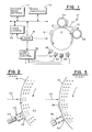
- FIG. 1 is a schematic diagram of an electrophotographic imaging system.
- FIG. 2 is a partial view of the system of Fig. 1 that illustrates normal toning of a photoconductive surface using a discharge area development method.
- FIG. 3 is a partial view of the electrophotographic surface of Fig. 1 that illustrates normal toning of a photoconductive surface using a charge area development method.
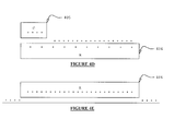
- FIG. 4 is an exploded view that illustrates normal toning of a photoconductive surface using a discharge area development method for a multi-color imaging system.
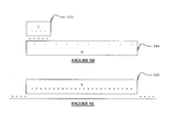
- FIG. 5 is an exploded view of the electrophotographic surface showing normal toning of a photoconductive surface using a charge area development method for a multi-color imaging system.
- Turning to Fig. 1, a
color electrophotography system 10 comprises adrum 12 that is coated, in the known manner, with aphotoconductive surface 14. While adrum 12 is shown, those skilled in the art will realize that any continuousphotoconductive surface 14 may be employed with this invention. Anelectrostatic charging station 16 chargesphotoconductive surface 14 as it passes therebeneath. Alaser 18 subsequently exposes selected areas of pre-chargedphotoconductive surface 14 to create image areas that exhibit a different charge level. - Using the customary principles of discharge area development (DAD),
photoconductive surface 14 must be capable of charging to the same sign of electrical potential as charges on a toner to be subsequently used for development. For example, whenphotoconductive surface 14 is charged by electrostatic chargingstation 16 to a positive potential, the color toner must also have a positive charge. The invention may also be implemented whenphotoconductive surface 14 is pre-charged to a negative potential and the toner is negatively charged. - Using the DAD process,
laser 18 discharges selected areas onphotoconductive surface 14. Thus, assuming that electrostatic chargingstation 16 causes photoconductivesurface 14 to have a high positive potential,laser 18 acts to dischargephotoconductive surface 14 to a more negative potential. It is to be understood that the potential values to be hereafter described are relative to each other and not with respect to any absolute value or measure. - In Fig. 2,
photoconductive surface 14 is shown after having been charged to a high positive potential by electrostatic chargingstation 16.Beam 20 fromlaser 18 reduces (i.e., "discharges") the charge potential onelectrostatic surface 14 to a more negative level in accordance with applied image signals. When a dischargedarea 22 reaches the vicinity of atoner supply 24, controlling signals are applied which enable release of positively chargedtoner particles 26 that adhere to dischargedarea 22 to produce adeveloped spot 28. - The CAD process is shown in Fig. 3. Here,
photoconductor surface 14 is initially charged by electrostatic chargingstation 16 to a high positive value.Laser beam 20 is controlled to discharge non-image areas ofphotoconductive surface 14 as it passes therebeneath. Areas ofphotoconductive surface 14 that are not exposed to the laser retain their high positive charge. The adjoining areas ofphotoconductive surface 14 exhibit a relatively negative potential and, as a result, exert a repulsive action that prevents the negatively charged toner particles from depositing thereon. - Returning to Fig. 1,
electrophotographic system 10 is controlled by amicroprocessor 30 which, in combination with image information inraster image buffer 32, feeds image data tolaser 18 throughlaser control circuit 34.Microprocessor 30 also issues signals to operate tonersupply control module 36 which in turn generates signals to control cyan, yellow, magenta, and black toner supplies 38, 40, 42, and 44, respectively. Atoner conditioning roller 48 both compresses and heats toner applied tophotoconductive surface 14. Atransfer roller 50 provides both heat and pressure to amedia sheet 52 thereby enabling toner transfer to occur fromphotoconductive surface 14 tomedia sheet 52. - In performing a color printing action, raster image buffers 22 contain at least three color planes, e.g., cyan, yellow and magenta. In synchronism with the rotation of
drum 12, a color plane is read out and controlslaser 18 to cause the particular color plane image to be produced onphotoconductive surface 14.Toner supply control 36 then causes the appropriate toner module (e.g., cyan module 38), to operate and to develop the exposed cyan image onphotoconductive surface 14. That image is then conditioned byroller 48 and proceeds arounddrum 12, past electrostatic chargingstation 16 wherephotoconductive surface 14 is again charged. A second color plane from raster image buffers 32 is then read out and controlslaser 18 to discharge areas ofphotoconductive surface 14 that are to be developed using a second color toner. (At this point, it is to be noted that there is no media sheet present in contact withdrum 12 and such contact will not occur until all color planes have been read out to controllaser 18 to produce registered images.) The expo- sure/development actions proceed through the cyan, yellow, magenta and black toner stations, in sequence, untilphotoconductive surface 14 has been toned in accordance with the image information contained in all raster image buffers 32. - The desired image is developed on the OPC with the toners that can charge to the same sign as the photoconductor, using the customary principles of discharge area development (DAD). When it is time to develop the opposite charging toners, the print mode is changed to the CAD method. The OPC is charged and the laser discharges all NON-imaged areas. The background area, rather than the imaged area is now discharged, a process called "writing white." The opposite sign toner layer develops in all areas remaining charged.
- To aid the reader's understanding of the present invention, a simple example showing both the DAD method and the present invention follows.
- Referring first to Fig. 4A, the Organic Photoconductor (OPC) is first charged, in this case to a positive charge. Next, the laser writes black by selectively discharging those areas to which toner is to be applied. In Fig. 4A the
color yellow 401 is added as a base layer. Yellow 401 having a positive charge is electrostatically attracted to the organic photoconductor in the areas the laser has discharged. - In Fig. 4B,
magenta 402 is added to the underlyingyellow coat 401 to create the color red. Because yellow 401 has been charged by the charging device to a positive charge, those areas where themagenta 402 is to be attached are selectively discharged. Here,magenta 402 having a positive charge is attracted to the relatively less positive charged areas of yellow 401. In Fig. 4C,cyan 403 is to be added to the underlying yellow 401 to create the color green. Both the yellow 401 and theadditional magenta 402 must first be charged positively. Areas to which the green is to be printed are then selectively discharged by the laser.Cyan 403 with its positive charge is again electrostatically attracted to the relatively negative charged areas. Figure 4D shows a similar arrangement whereincyan 405 is being deposited on an underlying coat ofmagenta 404 to create blue. Finally, in Fig. 4E, a layer of theblack toner 406 is deposited on the organic photoconductor. - Reviewing Fig. 4, the DAD process was used throughout. First, the underlying structure was charged positively. Next, selective areas were discharged wherein the toner to be applied was electrostatically attracted to those discharged areas.
- Fig. 5 shows how, by using a mix of CAD and DAD processes, toners of either positive or negative electrostatic charges can be used. In Fig. 5A, a positively charged
yellow toner 501 is applied using the DAD process to the organic photoconductor. As has been described earlier, the photoconductor is first charged positively and then selectively discharged in those areas to which the toner is to be applied. Once the organic photoconductor has been discharged it is brought into contact with the positively chargedyellow toner 501. - Next, in Fig. 5B a negatively charged
toner magenta 502 is applied to the positively charged yellow 501 to create the color red. Again, thetoner 501 is charged to a relatively positively level. Those areas to which themagenta toner 502 is not to be applied are discharged. Thus, toner yellow 501 has areas of relatively positive charge to whichmagenta toner 502 is electrostatically attracted. - In a similar manner, Fig. 5C shows green being created using the CAD method. Looking at Fig. 5D, the CAD method is used again to combine
cyan 505 withmagenta 504 to create the color blue. Here, theunderlying magenta 504 has a relatively negative charge as well as thecyan 505. Again, theunderlying color magenta 504 is first charged to a positive charge. Next, using the CAD method those areas to which the cyan is not to be added are discharged leaving select areas of the magenta 504 with relatively positive charges. This is then brought into contact with the cyan toner. Thecyan toner 505 is electrostatically attracted to those areas of the magenta 504 that still exhibit the relatively positive charge. Finally, in Fig. 5E thecolor black 506 is added using the DAD process as described earlier. - Thus summarizing Fig. 5, toners can be added using either the DAD or CAD process thereby alleviating the requirement that all toners exhibit the same electrostatic properties. By removing this requirement the constraints on the selection of toner, while not completely removed, are at least reduced in number.
- As understood by one skilled in the art, the above method allows for the majority of the toners charge to the opposite sign of the photoconductor, and the minority of the toners develop the same sign as the photo-conductor. With this embodiment the charge area development method is used for the toners with sign opposite the photoconductor and DAD is used for the others. This embodiment is less preferred because the printed dots are cupped and are more prone to jagged edges on the image. One skilled in the art would also understand that an alternative method to that described above is to use an intermediate medium wherein the individual color planes are transferred from the photoconductive surface to the intermediate medium.
- In conclusion, with the present invention, toner selection may be based on criteria other than their capability to charge to a particular sign. This allows selection from a far greater group of candidate pigments. Both negatively and positively charged toner particles may be used in the same printer.
- Although the preferred embodiment of the invention has been illustrated, and that form described, it is readily apparent to those skilled in the art that various modifications may be made therein without departing from the spirit of the invention or from the scope of the appended claims.
Claims (10)
Applications Claiming Priority (2)
| Application Number | Priority Date | Filing Date | Title |
|---|---|---|---|
| US196937 | 1994-02-15 | ||
| US08/196,937 US5450189A (en) | 1994-02-15 | 1994-02-15 | Electrophotographic imaging with toners of opposite sign electrical charge |
Publications (3)
| Publication Number | Publication Date |
|---|---|
| EP0667564A2 true EP0667564A2 (en) | 1995-08-16 |
| EP0667564A3 EP0667564A3 (en) | 1995-12-13 |
| EP0667564B1 EP0667564B1 (en) | 1998-02-25 |
Family
ID=22727363
Family Applications (1)
| Application Number | Title | Priority Date | Filing Date |
|---|---|---|---|
| EP94114619A Expired - Lifetime EP0667564B1 (en) | 1994-02-15 | 1994-09-16 | Electrophotographic imaging with toners of opposite sign electrical charge |
Country Status (4)
| Country | Link |
|---|---|
| US (1) | US5450189A (en) |
| EP (1) | EP0667564B1 (en) |
| JP (1) | JPH07281499A (en) |
| DE (1) | DE69408658T2 (en) |
Cited By (2)
| Publication number | Priority date | Publication date | Assignee | Title |
|---|---|---|---|---|
| EP0732632A1 (en) * | 1995-03-15 | 1996-09-18 | Hewlett-Packard Company | Multiple cartridge keying apparatus |
| EP0785478A3 (en) * | 1996-01-17 | 2001-01-03 | NexPress Solutions LLC | Method for forming toner images with two distinct toners |
Families Citing this family (5)
| Publication number | Priority date | Publication date | Assignee | Title |
|---|---|---|---|---|
| US5515155A (en) * | 1995-06-07 | 1996-05-07 | Xerox Corporation | Method and apparatus for establishing exposure and developer set points for color image formation |
| US6184914B1 (en) | 1999-08-09 | 2001-02-06 | Hewlett-Packard Company | Electrophotographic printing system and method, using toners that exhibit different charge states |
| US7403214B2 (en) * | 2006-02-21 | 2008-07-22 | Lexmark International, Inc. | Systems and methods for adjusting the dynamic range of a scanning laser beam |
| US7920810B2 (en) | 2007-08-15 | 2011-04-05 | Hewlett-Packard Development Company, L.P. | Electrophotography device with electric field applicator |
| CN111688336B (en) * | 2020-06-04 | 2021-08-17 | 莒南县海达塑料包装制品有限公司 | Novel gravure press |
Citations (4)
| Publication number | Priority date | Publication date | Assignee | Title |
|---|---|---|---|---|
| JPS5883863A (en) * | 1981-11-13 | 1983-05-19 | Casio Comput Co Ltd | Electrostatic latent image forming method for electronic copying device |
| US5155541A (en) * | 1991-07-26 | 1992-10-13 | Xerox Corporation | Single pass digital printer with black, white and 2-color capability |
| US5194351A (en) * | 1990-12-21 | 1993-03-16 | Xerox Corporation | Single pass digital xerographic process color reproduction |
| US5241358A (en) * | 1989-11-22 | 1993-08-31 | Xerox Corporation | Biasing scheme for improving latitudes in the tri-level xerographic process |
Family Cites Families (1)
| Publication number | Priority date | Publication date | Assignee | Title |
|---|---|---|---|---|
| US5241359A (en) * | 1989-11-22 | 1993-08-31 | Xerox Corporation | Biasing switching between tri-level and bi-level development |
-
1994
- 1994-02-15 US US08/196,937 patent/US5450189A/en not_active Expired - Lifetime
- 1994-09-16 EP EP94114619A patent/EP0667564B1/en not_active Expired - Lifetime
- 1994-09-16 DE DE69408658T patent/DE69408658T2/en not_active Expired - Fee Related
-
1995
- 1995-02-15 JP JP7026361A patent/JPH07281499A/en active Pending
Patent Citations (4)
| Publication number | Priority date | Publication date | Assignee | Title |
|---|---|---|---|---|
| JPS5883863A (en) * | 1981-11-13 | 1983-05-19 | Casio Comput Co Ltd | Electrostatic latent image forming method for electronic copying device |
| US5241358A (en) * | 1989-11-22 | 1993-08-31 | Xerox Corporation | Biasing scheme for improving latitudes in the tri-level xerographic process |
| US5194351A (en) * | 1990-12-21 | 1993-03-16 | Xerox Corporation | Single pass digital xerographic process color reproduction |
| US5155541A (en) * | 1991-07-26 | 1992-10-13 | Xerox Corporation | Single pass digital printer with black, white and 2-color capability |
Non-Patent Citations (1)
| Title |
|---|
| PATENT ABSTRACTS OF JAPAN, unexamined applications, P section, vol. 7, no. 180, August 9, 1983 THE PATENT OFFICE JAPANESE GOVERNMENT page 130 P 215; & JP-A-58 83 863 (CASIO) * |
Cited By (2)
| Publication number | Priority date | Publication date | Assignee | Title |
|---|---|---|---|---|
| EP0732632A1 (en) * | 1995-03-15 | 1996-09-18 | Hewlett-Packard Company | Multiple cartridge keying apparatus |
| EP0785478A3 (en) * | 1996-01-17 | 2001-01-03 | NexPress Solutions LLC | Method for forming toner images with two distinct toners |
Also Published As
| Publication number | Publication date |
|---|---|
| EP0667564A3 (en) | 1995-12-13 |
| US5450189A (en) | 1995-09-12 |
| EP0667564B1 (en) | 1998-02-25 |
| JPH07281499A (en) | 1995-10-27 |
| DE69408658T2 (en) | 1998-08-20 |
| DE69408658D1 (en) | 1998-04-02 |
Similar Documents
| Publication | Publication Date | Title |
|---|---|---|
| US5337136A (en) | Tandem trilevel process color printer | |
| EP0577597B1 (en) | Imaging system with intermediate transfer members | |
| JPH02184873A (en) | Formation of pseudo color image using two different coloring agents/toners | |
| US5347353A (en) | Tandem high productivity color architecture using a photoconductive intermediate belt | |
| US5740510A (en) | Electrostatographic multicolour printing apparatus for single pass sequential duplex printing on a web-type toner receptor material | |
| US5012293A (en) | Transfer station control in an electrophotographic reproduction device | |
| US5361089A (en) | Method and apparatus for applying an adhesive layer for improved image transfer in electrophotography | |
| US6895204B2 (en) | Electrophotographic printer having image charging unit to reduce adhesive force of transferred image and method thereof | |
| US5450189A (en) | Electrophotographic imaging with toners of opposite sign electrical charge | |
| US4970536A (en) | Apparatus for multicolor image forming wherein image forming conditions are adjusted based on reference images | |
| JP2002341606A (en) | Image forming apparatus | |
| US5194351A (en) | Single pass digital xerographic process color reproduction | |
| US6184914B1 (en) | Electrophotographic printing system and method, using toners that exhibit different charge states | |
| US5459563A (en) | Method of forming a multicolor toner image on a photoreceptor and transferring the formed image to a recording sheet | |
| US5206101A (en) | Method of and apparatus for forming a multi-color image | |
| US20030203294A1 (en) | Method for producing developed electrostatic images using multiple toner fountains | |
| US20030036009A1 (en) | Method for producing developed electrostatic images using multiple toner fountains | |
| US4914483A (en) | Electrostatographic transfer with artifact suppression | |
| EP1152299A2 (en) | Color laser printer apparatus | |
| JP2530813Y2 (en) | Multi-color printing device | |
| US6131000A (en) | Electrophotographic printing apparatus using electric potential dividing development | |
| EP0319098B1 (en) | Electrostatic proofing of negative color separations | |
| US20030027062A1 (en) | Method for producing developed electrostatic images using reduced density color toners | |
| JP2002091165A (en) | Image forming device and color image forming device | |
| JPH06175461A (en) | Color image forming device |
Legal Events
| Date | Code | Title | Description |
|---|---|---|---|
| PUAI | Public reference made under article 153(3) epc to a published international application that has entered the european phase |
Free format text: ORIGINAL CODE: 0009012 |
|
| AK | Designated contracting states |
Kind code of ref document: A2 Designated state(s): DE FR GB IT |
|
| PUAL | Search report despatched |
Free format text: ORIGINAL CODE: 0009013 |
|
| AK | Designated contracting states |
Kind code of ref document: A3 Designated state(s): DE FR GB IT |
|
| 17P | Request for examination filed |
Effective date: 19960119 |
|
| 17Q | First examination report despatched |
Effective date: 19970307 |
|
| GRAG | Despatch of communication of intention to grant |
Free format text: ORIGINAL CODE: EPIDOS AGRA |
|
| GRAG | Despatch of communication of intention to grant |
Free format text: ORIGINAL CODE: EPIDOS AGRA |
|
| GRAH | Despatch of communication of intention to grant a patent |
Free format text: ORIGINAL CODE: EPIDOS IGRA |
|
| GRAH | Despatch of communication of intention to grant a patent |
Free format text: ORIGINAL CODE: EPIDOS IGRA |
|
| GRAA | (expected) grant |
Free format text: ORIGINAL CODE: 0009210 |
|
| ITF | It: translation for a ep patent filed | ||
| AK | Designated contracting states |
Kind code of ref document: B1 Designated state(s): DE FR GB IT |
|
| REF | Corresponds to: |
Ref document number: 69408658 Country of ref document: DE Date of ref document: 19980402 |
|
| ET | Fr: translation filed | ||
| PLBE | No opposition filed within time limit |
Free format text: ORIGINAL CODE: 0009261 |
|
| STAA | Information on the status of an ep patent application or granted ep patent |
Free format text: STATUS: NO OPPOSITION FILED WITHIN TIME LIMIT |
|
| 26N | No opposition filed | ||
| REG | Reference to a national code |
Ref country code: GB Ref legal event code: 732E |
|
| REG | Reference to a national code |
Ref country code: FR Ref legal event code: TP |
|
| REG | Reference to a national code |
Ref country code: GB Ref legal event code: IF02 |
|
| PGFP | Annual fee paid to national office [announced via postgrant information from national office to epo] |
Ref country code: GB Payment date: 20050908 Year of fee payment: 12 |
|
| PGFP | Annual fee paid to national office [announced via postgrant information from national office to epo] |
Ref country code: FR Payment date: 20050919 Year of fee payment: 12 |
|
| PGFP | Annual fee paid to national office [announced via postgrant information from national office to epo] |
Ref country code: IT Payment date: 20060930 Year of fee payment: 13 |
|
| PGFP | Annual fee paid to national office [announced via postgrant information from national office to epo] |
Ref country code: DE Payment date: 20061031 Year of fee payment: 13 |
|
| GBPC | Gb: european patent ceased through non-payment of renewal fee |
Effective date: 20060916 |
|
| REG | Reference to a national code |
Ref country code: FR Ref legal event code: ST Effective date: 20070531 |
|
| PG25 | Lapsed in a contracting state [announced via postgrant information from national office to epo] |
Ref country code: GB Free format text: LAPSE BECAUSE OF NON-PAYMENT OF DUE FEES Effective date: 20060916 |
|
| PG25 | Lapsed in a contracting state [announced via postgrant information from national office to epo] |
Ref country code: FR Free format text: LAPSE BECAUSE OF NON-PAYMENT OF DUE FEES Effective date: 20061002 |
|
| PG25 | Lapsed in a contracting state [announced via postgrant information from national office to epo] |
Ref country code: DE Free format text: LAPSE BECAUSE OF NON-PAYMENT OF DUE FEES Effective date: 20080401 |
|
| PG25 | Lapsed in a contracting state [announced via postgrant information from national office to epo] |
Ref country code: IT Free format text: LAPSE BECAUSE OF NON-PAYMENT OF DUE FEES Effective date: 20070916 |