EP0667277B1 - Système anti-remontée de l'axe volant d'une colonne de direction - Google Patents
Système anti-remontée de l'axe volant d'une colonne de direction Download PDFInfo
- Publication number
- EP0667277B1 EP0667277B1 EP19950400211 EP95400211A EP0667277B1 EP 0667277 B1 EP0667277 B1 EP 0667277B1 EP 19950400211 EP19950400211 EP 19950400211 EP 95400211 A EP95400211 A EP 95400211A EP 0667277 B1 EP0667277 B1 EP 0667277B1
- Authority
- EP
- European Patent Office
- Prior art keywords
- sleeve
- steering column
- movable axis
- column according
- axis
- Prior art date
- Legal status (The legal status is an assumption and is not a legal conclusion. Google has not performed a legal analysis and makes no representation as to the accuracy of the status listed.)
- Expired - Lifetime
Links
Images


Classifications
-
- B—PERFORMING OPERATIONS; TRANSPORTING
- B62—LAND VEHICLES FOR TRAVELLING OTHERWISE THAN ON RAILS
- B62D—MOTOR VEHICLES; TRAILERS
- B62D1/00—Steering controls, i.e. means for initiating a change of direction of the vehicle
- B62D1/02—Steering controls, i.e. means for initiating a change of direction of the vehicle vehicle-mounted
- B62D1/16—Steering columns
- B62D1/18—Steering columns yieldable or adjustable, e.g. tiltable
- B62D1/19—Steering columns yieldable or adjustable, e.g. tiltable incorporating energy-absorbing arrangements, e.g. by being yieldable or collapsible
- B62D1/192—Yieldable or collapsible columns
-
- B—PERFORMING OPERATIONS; TRANSPORTING
- B62—LAND VEHICLES FOR TRAVELLING OTHERWISE THAN ON RAILS
- B62D—MOTOR VEHICLES; TRAILERS
- B62D1/00—Steering controls, i.e. means for initiating a change of direction of the vehicle
- B62D1/02—Steering controls, i.e. means for initiating a change of direction of the vehicle vehicle-mounted
- B62D1/16—Steering columns
- B62D1/18—Steering columns yieldable or adjustable, e.g. tiltable
- B62D1/19—Steering columns yieldable or adjustable, e.g. tiltable incorporating energy-absorbing arrangements, e.g. by being yieldable or collapsible
- B62D1/197—Steering columns yieldable or adjustable, e.g. tiltable incorporating energy-absorbing arrangements, e.g. by being yieldable or collapsible incorporating devices for preventing ingress of the steering column into the passengers space in case of accident
Definitions
- the present invention relates to a motor vehicle steering column comprising a steering wheel guided and mounted in a column body rigidly connected to the vehicle structure.
- This steering column has an anti-lift system of the steering wheel in the event of an impact.
- Document US-3,791,233 describes a column of vehicle steering comprising the features defined in the preamble of claim 1. It includes a steering wheel and a steering wheel assembly which extends between the steering wheel and the transmission means of movement from the steering wheel to the wheels.
- the flywheel assembly is divided into an upper part carrying the steering wheel and a lower part fixed to the motion transmission means. Both parties are arranged coaxially for a telescopic relative movement.
- Document LU-A-56385 concerns a steering column for vehicle.
- This column includes, at its lower part, an area to corrugated bellows-shaped wall used to absorb shocks.
- the purpose of the present invention is to provide an anti-rise system of the steering wheel axis of the column direction which allows in case of shock to know exactly the extreme position that the flying axis will have with the steering wheel, in relation to the dashboard, that is to say in relation to the driver.
- Another object of the invention is still to have a flywheel anti-rise system the steering column can be combined with a anti-theft system.
- the subject of the invention is a column of direction as set forth in claim 1.
- the steering column is fitted with an anti-theft system.
- the inner sleeve has at least one axial opening in the cylindrical part so to pass an anti-theft system bolt.
- the axis of steering wheel is free to rotate when the anti-theft system is not activated.
- the bolt of the anti-theft system is introduced into a sleeve opening provided for this purpose, and blocks in rotation the steering wheel axis.
- the offset of the flying axis between these two parts cylindrical is a conical part which has the same axis that said cylindrical parts, and which may have an angle of the order of 45 ° relative to this axis of the cylindrical parts.
- the transverse wall of the shoulder of the inner sleeve has a conical part of connection with the cylindrical part, so that what it cooperates with the conical part column body.
- this sleeve is a single piece.
- the sleeve is formed either by a rolled sheet or by a molded part, either by a struck part, or either by a machined part.
- the steering column fitted with the system anti-rise of the flywheel axis according to the invention thus has the advantage of limiting precisely moving the axle and the steering wheel from the front to the rear of the vehicle in the event of an impact, which eliminate driver injuries on the steering wheel during an impact.
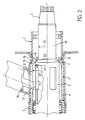
- the steering column shown on the Figures includes a flywheel axis 1, which is guided and mounted by one or two bearings 3 in the body of column 2.
- the body of column 2 is itself fixed rigidly to a column support 4, which is connected to the structure of the motor vehicle.
- An internal sleeve 5 is mounted inside the column body 2, with which it is integral.
- This inner sleeve 5 is arranged in the area where is arranged the anti-theft system consisting of a cartridge anti-theft 14 comprising a bolt 13.
- This cartridge anti-theft device 14 is mounted in a tube which is fixed to the column body 2.
- the sleeve internal 5 is provided with an axial opening 12.
- the internal sleeve 5 fulfills a reinforcement function of the anti-theft system.
- the internal sleeve 5 is constituted by a cylindrical part 6 which has an internal diameter D 1 .
- the external end of this cylindrical part 6 is provided with a shoulder 7, which is constituted by a transverse wall having a circular opening 8 of diameter D 2 .
- the wall transverse of the shoulder 7 of this internal sleeve 5 has a conical part 15 for connection with the cylindrical part 6.
- This conical part 15 is arranged so that it can cooperate with a corresponding conical part 16 of the body of column 2, so that the inner sleeve has a correctly determined axial position relative to the column body 2, with which it is integral.
- the conical part 15 of the inner sleeve 5 and the conical part 16 of the body column 2 do not have the same angle.
- the conical part 15 of the inner sleeve 5, and the conical part 16 of the body of column 2 both have the same cone angle.
- the flywheel axis 1 comprises two cylindrical parts referenced respectively 9 and 10.
- the cylindrical part 9 has a diameter d 1
- the cylindrical part 10 has a diameter d 2 .
- the diameter d 1 is larger than the diameter d 2 and the two cylindrical parts 9 and 10 are connected by a step 11.
- the internal diameter D 1 of the internal sleeve 5 is greater than the diameter d 1 of the cylindrical part 9 of the flywheel axis 1 , while the diameter D 2 of the circular opening 8 of the internal sleeve 5 is larger than the diameter d 2 of the cylindrical part 10 of the flywheel axis 1.
- the diameter d 1 of the cylindrical part 9 of the flywheel axis 1 is larger than the diameter D 2 of the circular opening 8 of the internal sleeve 5.
- the shoulder 7 of the internal sleeve 5 and the recess 11 of the flywheel axis 1 are arranged axially with respect to each other, so that it is moved away from a predetermined value L.
- This value L represents the travel of the flywheel axis 1 when the recess 11 abuts against the shoulder 7 of the internal sleeve 5, during an impact.
- the offset 11 of the flywheel axis 1 between the two cylindrical parts 9 and 10 is a conical part, which has the same axis as said cylindrical parts 9 and 10.
- this angle is of the order of 45 ° by relative to the axis of the cylindrical parts 9 and 10.
- the sleeve 5 is a single piece as is shown in Figures.
- realization of this inner sleeve 5 can be constituted by a rolled sheet, or by a part molded, or by a coin struck, or even by a machined part.
- An embodiment of the invention thus provides a anti-rise system of the steering wheel axis which integrates also the anti-theft reinforcement function, which acts by interference between the flywheel axis 1 and the sleeve internal 5 secured to the column body 2.
- the internal sleeve 5 thus fulfills two functions. First of all, it participates in maintaining the anti-theft cartridge 14 through the axial opening 12, and it thus takes up the efforts for the column body 2, when a torque is applied to the steering wheel during a break-in. A second function of this internal sleeve 5 is given by the shoulder 7 with its opening D 2 , which prevents the rise of the flywheel axis 1, due to the interference with the conical recess 11 of this flywheel axis 1. From this fact, the intrusion of the steering wheel during an impact on the vehicle is limited to the stroke of a predetermined value L, which represents the axial spacing with respect to each other of the recess 11 with the opening circular 8 of the shoulder 7.
- the flywheel axis 1 thus consists of an area comprising the cylindrical part 9 and which receives the bolt 13 of the anti-theft cartridge 14. To do this, this cylindrical part 9 is provided with several axial openings 17, which are intended to receive the end of the bolt when the flywheel is in the locked position. This zone is arranged to be able to withstand the forces generated by the torque applied to the steering wheel during a break-in which is of the order of 200 mN.
- the flywheel axis 1 comprises the cylindrical part 10 which allows connection with the flywheel which is not shown in the Figures.
- An intermediate zone between the two cylindrical parts 9 and 10 is formed by the recess 11, which in the Figures is produced by a conical part at 45 °, this zone coming to interfere with the diameter D 2 of the internal sleeve 5.
- the steering wheel axis 1 receives a thrust from the front of the vehicle towards the rear.
- the flywheel axis 1 then moves by the predetermined value L by assembly, before contact between the flywheel axis 1 and the internal sleeve 5.
- the interference which exists because the diameter d1 of the cylindrical part 9 of the axis flywheel 1 is larger than the diameter D 2 of the circular opening 8 of the internal sleeve 5 is such that the flywheel axis is blocked under a force of the order of 15,000 N.
- the anti-rise system of the steering wheel axis of the steering column makes it possible to precisely determine the stroke of the steering wheel axis and its position after an impact, which makes it possible to limit, if not eliminate, the injuries which a driver would suffer on the steering wheel or the dashboard during the impact of this vehicle.
Landscapes
- Engineering & Computer Science (AREA)
- Chemical & Material Sciences (AREA)
- Combustion & Propulsion (AREA)
- Transportation (AREA)
- Mechanical Engineering (AREA)
- Steering Controls (AREA)
Description
Claims (11)
- Colonne de direction comportant un axe-volant (1) guidé et monté par un palier (3) dans un corps de colonne (2), qui est fixé rigidement à un support de colonne (4), ledit support étant relié à la structure du véhicule automobile, ladite colonne comportant un système anti-remontée de l'axe-volant, comprenant un manchon interne (5) solidaire dudit corps de colonne, ladite colonne étant caractérisée en ce que le manchon (5) présente une partie cylindrique (6) de diamètre interne D1 dont une extrémité est munie d'un épaulement (7) constitué par une paroi transversale avec une ouverture circulaire (8) de diamètre D2, l'axe-volant (1) ayant deux parties cylindriques (9, 10) de diamètres différents d1 et d2, raccordées par un décrochement (11), D1 étant plus grand que d1, D2 étant plus grand que d2, le diamètre d1 de l'axe-volant (1) étant plus grand que le diamètre D2 de l'ouverture circulaire (8), l'épaulement (7) du manchon (5) et le décrochement (11) de l'axe-volant (1) étant disposés axialement l'un par rapport à l'autre et écartés d'une valeur prédéterminée qui, lors d'un choc, représente la course de l'axe volant (1) dont le décrochement (11) vient alors buter contre l'épaulement (7) du manchon (5).
- Colonne de direction selon la revendication 1, caractérisée en ce que l'axe-volant est guidé et monté par deux paliers.
- Colonne de direction selon l'une des revendications 1 ou 2, caractérisée en ce qu'elle est munie d'un système antivol (14), l'axe du volant (1) étant libre en rotation lorsque le système antivol (14) est non actionné, le manchon (5) ayant au moins une ouverture axiale (12) dans la partie cylindrique (6) de manière à laisser passer un pêne (13) du système antivol (14).
- Colonne de direction selon l'une quelconque des revendications précédentes, caractérisée en ce que le décrochement (11) de l'axe volant (1) entre les deux parties cylindriques (9) et (10) est une partie conique ayant le même axe que lesdites parties cylindriques (9, 10).
- Colonne de direction selon la revendication 4, caractérisée en ce que le décrochement (11) est une partie conique ayant un angle de l'ordre de 45° par rapport à l'axe des parties cylindriques (9, 10).
- Colonne de direction selon la revendication 5, caractérisée en ce que la paroi transversale de l'épaulement (7) du manchon (5) comporte une partie conique (15) de raccordement avec la partie cylindrique (6), de manière qu'elle coopère avec la partie conique (16) correspondante du corps de colonne (2).
- Colonne de direction selon l'une quelconque des revendications précédentes, caractérisée en ce que le manchon (5) est une pièce monobloc.
- Colonne de direction selon la revendication 7, caractérisée en ce que le manchon (5) est constitué par une tôle roulée.
- Colonne de direction selon la revendication 7, caractérisée en ce que le manchon (5) est constitué par une pièce moulée.
- Colonne de direction selon la revendication 7, caractérisée en ce que le manchon (5) est constitué par une pièce frappée.
- Colonne de direction selon la revendication 7, caractérisée en ce que le manchon (5) est constitué par une pièce usinée.
Applications Claiming Priority (2)
| Application Number | Priority Date | Filing Date | Title |
|---|---|---|---|
| FR9401473A FR2715907B1 (fr) | 1994-02-09 | 1994-02-09 | Système anti-remontée de l'axe volant d'une colonne de direction. |
| FR9401473 | 1994-02-09 |
Publications (2)
| Publication Number | Publication Date |
|---|---|
| EP0667277A1 EP0667277A1 (fr) | 1995-08-16 |
| EP0667277B1 true EP0667277B1 (fr) | 1998-03-25 |
Family
ID=9459932
Family Applications (1)
| Application Number | Title | Priority Date | Filing Date |
|---|---|---|---|
| EP19950400211 Expired - Lifetime EP0667277B1 (fr) | 1994-02-09 | 1995-02-01 | Système anti-remontée de l'axe volant d'une colonne de direction |
Country Status (4)
| Country | Link |
|---|---|
| EP (1) | EP0667277B1 (fr) |
| DE (1) | DE69501839T2 (fr) |
| ES (1) | ES2113715T3 (fr) |
| FR (1) | FR2715907B1 (fr) |
Families Citing this family (1)
| Publication number | Priority date | Publication date | Assignee | Title |
|---|---|---|---|---|
| DE102007028770B4 (de) * | 2007-06-22 | 2019-08-14 | Dr. Ing. H.C. F. Porsche Aktiengesellschaft | Lenksäulenanordnung für ein Kraftfahrzeug |
Family Cites Families (3)
| Publication number | Priority date | Publication date | Assignee | Title |
|---|---|---|---|---|
| FR1539058A (fr) * | 1967-07-13 | 1968-09-13 | Citroen Sa Andre | Colonne de direction pour véhicule |
| US3791233A (en) * | 1972-11-06 | 1974-02-12 | Volvo Ab | Collapsible vehicle-steering systems |
| FR2668442B1 (fr) * | 1990-10-30 | 1994-11-18 | Nacam | Colonne de direction a dispositif absorbeur d'energie. |
-
1994
- 1994-02-09 FR FR9401473A patent/FR2715907B1/fr not_active Expired - Fee Related
-
1995
- 1995-02-01 DE DE1995601839 patent/DE69501839T2/de not_active Expired - Fee Related
- 1995-02-01 EP EP19950400211 patent/EP0667277B1/fr not_active Expired - Lifetime
- 1995-02-01 ES ES95400211T patent/ES2113715T3/es not_active Expired - Lifetime
Also Published As
| Publication number | Publication date |
|---|---|
| FR2715907A1 (fr) | 1995-08-11 |
| EP0667277A1 (fr) | 1995-08-16 |
| DE69501839T2 (de) | 1998-08-13 |
| ES2113715T3 (es) | 1998-05-01 |
| FR2715907B1 (fr) | 1996-04-19 |
| DE69501839D1 (de) | 1998-04-30 |
Similar Documents
| Publication | Publication Date | Title |
|---|---|---|
| EP0755843B1 (fr) | Colonne de direction réglable en profondeur, avec dispositif de guidage | |
| EP0755844B1 (fr) | Dispositif d'absorption d'énergie et de guidage pour colonne de direction de véhicule automobile | |
| EP3145790B1 (fr) | Mécanisme de colonne de direction ajustable en profondeur à butée escamotable | |
| FR2504864A1 (fr) | Suspension pour le groupe moteur d'un vehicule dispose a l'avant, plus specialement transversalement | |
| FR3010037A1 (fr) | Vehicule comprenant un dispositif deflecteur et dispositif deflecteur | |
| EP0794103A1 (fr) | Dispositif antirotation de corps de colonne de direction de véhicule automobile | |
| EP0662413B1 (fr) | Dispositif d'absorption d'énergie pour colonne de direction de véhicule automobile | |
| EP3724057B1 (fr) | Colonne de direction à butée de fin de course de réglage | |
| EP1479578A2 (fr) | Dispositif de pédalier rétractable en cas de choc frontal sur un véhicule | |
| EP0634314B1 (fr) | Ensemble de colonne de direction rétractable axialement en cas de choc, notamment pour véhicule automobile | |
| FR2919560A1 (fr) | Structure de caisse de vehicule automobile et vehicule comportant une telle structure de caisse | |
| FR2713188A1 (fr) | Dispositif d'absorption d'énergie pour colonne de direction de véhicule automobile. | |
| FR2896470B1 (fr) | Colonne de direction avec moyeu de volant fixe et moyens de deplacement du volant de direction. | |
| FR2892993A1 (fr) | Dispositif aerodynamique pour un vehicule automobile et vehicule automobile comportant au moins un tel dispositif aerodynamique. | |
| EP0800978B1 (fr) | Ensemble de colonne de direction à absorption d'énergie de choc, notamment pour véhicule automobile | |
| FR2768203A1 (fr) | Securite d'engagement a basculement d'un dispositif de maintien en position d'un systeme de serrage de deux elements | |
| FR2676407A1 (fr) | Agencement d'une partie avant de vehicule automobile deformable en cas de choc frontal du vehicule. | |
| FR2749053A1 (fr) | Systeme vis-ecrou pour le reglage en position relative de deux elements mobiles l'un par rapport a l'autre, notamment pour le reglage en position d'un siege d'automobile | |
| EP0667277A1 (fr) | Système anti-remontée de l'axe volant d'une colonne de direction | |
| EP2379374A1 (fr) | Support de charnon mobile amortisseur de choc pieton | |
| EP0470888B1 (fr) | Colonne de direction notamment de véhicule automobile | |
| FR2881707A1 (fr) | Dispositif d'absorption instantanee d'energie d'une colonne de direction de vehicule automobile | |
| FR2740882A1 (fr) | Agencement perfectionne de supports de colonne de direction et de pedales dans un vehicule automobile | |
| EP2038163A2 (fr) | Dispositif de protection contre un choc frontal d'une cassette de refroidissement d'un vehicule | |
| EP0289397B1 (fr) | Pare-chocs pour véhicule automobile et véhicule équipé d'un tel pare-chocs |
Legal Events
| Date | Code | Title | Description |
|---|---|---|---|
| PUAI | Public reference made under article 153(3) epc to a published international application that has entered the european phase |
Free format text: ORIGINAL CODE: 0009012 |
|
| 17P | Request for examination filed |
Effective date: 19950603 |
|
| AK | Designated contracting states |
Kind code of ref document: A1 Designated state(s): DE ES GB |
|
| 17Q | First examination report despatched |
Effective date: 19960611 |
|
| GRAG | Despatch of communication of intention to grant |
Free format text: ORIGINAL CODE: EPIDOS AGRA |
|
| GRAG | Despatch of communication of intention to grant |
Free format text: ORIGINAL CODE: EPIDOS AGRA |
|
| GRAH | Despatch of communication of intention to grant a patent |
Free format text: ORIGINAL CODE: EPIDOS IGRA |
|
| GRAH | Despatch of communication of intention to grant a patent |
Free format text: ORIGINAL CODE: EPIDOS IGRA |
|
| GRAA | (expected) grant |
Free format text: ORIGINAL CODE: 0009210 |
|
| RAP1 | Party data changed (applicant data changed or rights of an application transferred) |
Owner name: LEMFOERDER NACAM SA |
|
| AK | Designated contracting states |
Kind code of ref document: B1 Designated state(s): DE ES GB |
|
| REF | Corresponds to: |
Ref document number: 69501839 Country of ref document: DE Date of ref document: 19980430 |
|
| REG | Reference to a national code |
Ref country code: ES Ref legal event code: FG2A Ref document number: 2113715 Country of ref document: ES Kind code of ref document: T3 |
|
| GBT | Gb: translation of ep patent filed (gb section 77(6)(a)/1977) |
Effective date: 19980506 |
|
| PLBE | No opposition filed within time limit |
Free format text: ORIGINAL CODE: 0009261 |
|
| STAA | Information on the status of an ep patent application or granted ep patent |
Free format text: STATUS: NO OPPOSITION FILED WITHIN TIME LIMIT |
|
| 26N | No opposition filed | ||
| PGFP | Annual fee paid to national office [announced via postgrant information from national office to epo] |
Ref country code: ES Payment date: 20000131 Year of fee payment: 6 |
|
| PGFP | Annual fee paid to national office [announced via postgrant information from national office to epo] |
Ref country code: GB Payment date: 20000202 Year of fee payment: 6 |
|
| PGFP | Annual fee paid to national office [announced via postgrant information from national office to epo] |
Ref country code: DE Payment date: 20000217 Year of fee payment: 6 |
|
| PG25 | Lapsed in a contracting state [announced via postgrant information from national office to epo] |
Ref country code: GB Free format text: LAPSE BECAUSE OF NON-PAYMENT OF DUE FEES Effective date: 20010201 |
|
| PG25 | Lapsed in a contracting state [announced via postgrant information from national office to epo] |
Ref country code: ES Free format text: LAPSE BECAUSE OF NON-PAYMENT OF DUE FEES Effective date: 20010202 |
|
| GBPC | Gb: european patent ceased through non-payment of renewal fee |
Effective date: 20010201 |
|
| PG25 | Lapsed in a contracting state [announced via postgrant information from national office to epo] |
Ref country code: DE Free format text: LAPSE BECAUSE OF NON-PAYMENT OF DUE FEES Effective date: 20011201 |
|
| REG | Reference to a national code |
Ref country code: ES Ref legal event code: FD2A Effective date: 20020916 |