EP0667120A2 - Needle-suture assembly and packaging system - Google Patents
Needle-suture assembly and packaging system Download PDFInfo
- Publication number
- EP0667120A2 EP0667120A2 EP95300202A EP95300202A EP0667120A2 EP 0667120 A2 EP0667120 A2 EP 0667120A2 EP 95300202 A EP95300202 A EP 95300202A EP 95300202 A EP95300202 A EP 95300202A EP 0667120 A2 EP0667120 A2 EP 0667120A2
- Authority
- EP
- European Patent Office
- Prior art keywords
- suture
- needle
- packaging
- package tray
- swaging
- Prior art date
- Legal status (The legal status is an assumption and is not a legal conclusion. Google has not performed a legal analysis and makes no representation as to the accuracy of the status listed.)
- Ceased
Links
Images


Classifications
-
- B—PERFORMING OPERATIONS; TRANSPORTING
- B65—CONVEYING; PACKING; STORING; HANDLING THIN OR FILAMENTARY MATERIAL
- B65H—HANDLING THIN OR FILAMENTARY MATERIAL, e.g. SHEETS, WEBS, CABLES
- B65H67/00—Replacing or removing cores, receptacles, or completed packages at paying-out, winding, or depositing stations
- B65H67/04—Arrangements for removing completed take-up packages and or replacing by cores, formers, or empty receptacles at winding or depositing stations; Transferring material between adjacent full and empty take-up elements
- B65H67/044—Continuous winding apparatus for winding on two or more winding heads in succession
-
- A—HUMAN NECESSITIES
- A61—MEDICAL OR VETERINARY SCIENCE; HYGIENE
- A61B—DIAGNOSIS; SURGERY; IDENTIFICATION
- A61B17/00—Surgical instruments, devices or methods, e.g. tourniquets
- A61B17/04—Surgical instruments, devices or methods, e.g. tourniquets for suturing wounds; Holders or packages for needles or suture materials
- A61B17/06—Needles ; Sutures; Needle-suture combinations; Holders or packages for needles or suture materials
- A61B17/06004—Means for attaching suture to needle
-
- A—HUMAN NECESSITIES
- A61—MEDICAL OR VETERINARY SCIENCE; HYGIENE
- A61B—DIAGNOSIS; SURGERY; IDENTIFICATION
- A61B17/00—Surgical instruments, devices or methods, e.g. tourniquets
- A61B17/04—Surgical instruments, devices or methods, e.g. tourniquets for suturing wounds; Holders or packages for needles or suture materials
- A61B17/06—Needles ; Sutures; Needle-suture combinations; Holders or packages for needles or suture materials
- A61B17/06114—Packages or dispensers for needles or sutures
- A61B17/06133—Packages or dispensers for needles or sutures of parallelepipedal shape, e.g. made of rectangular or slightly oval panels
-
- B—PERFORMING OPERATIONS; TRANSPORTING
- B65—CONVEYING; PACKING; STORING; HANDLING THIN OR FILAMENTARY MATERIAL
- B65H—HANDLING THIN OR FILAMENTARY MATERIAL, e.g. SHEETS, WEBS, CABLES
- B65H54/00—Winding, coiling, or depositing filamentary material
- B65H54/56—Winding of hanks or skeins
-
- A—HUMAN NECESSITIES
- A61—MEDICAL OR VETERINARY SCIENCE; HYGIENE
- A61B—DIAGNOSIS; SURGERY; IDENTIFICATION
- A61B17/00—Surgical instruments, devices or methods, e.g. tourniquets
- A61B17/04—Surgical instruments, devices or methods, e.g. tourniquets for suturing wounds; Holders or packages for needles or suture materials
- A61B17/0467—Instruments for cutting sutures
-
- A—HUMAN NECESSITIES
- A61—MEDICAL OR VETERINARY SCIENCE; HYGIENE
- A61B—DIAGNOSIS; SURGERY; IDENTIFICATION
- A61B17/00—Surgical instruments, devices or methods, e.g. tourniquets
- A61B2017/00526—Methods of manufacturing
-
- A—HUMAN NECESSITIES
- A61—MEDICAL OR VETERINARY SCIENCE; HYGIENE
- A61B—DIAGNOSIS; SURGERY; IDENTIFICATION
- A61B17/00—Surgical instruments, devices or methods, e.g. tourniquets
- A61B17/04—Surgical instruments, devices or methods, e.g. tourniquets for suturing wounds; Holders or packages for needles or suture materials
- A61B17/06—Needles ; Sutures; Needle-suture combinations; Holders or packages for needles or suture materials
- A61B17/06004—Means for attaching suture to needle
- A61B2017/06028—Means for attaching suture to needle by means of a cylindrical longitudinal blind bore machined at the suture-receiving end of the needle, e.g. opposite to needle tip
-
- A—HUMAN NECESSITIES
- A61—MEDICAL OR VETERINARY SCIENCE; HYGIENE
- A61B—DIAGNOSIS; SURGERY; IDENTIFICATION
- A61B50/00—Containers, covers, furniture or holders specially adapted for surgical or diagnostic appliances or instruments, e.g. sterile covers
- A61B2050/005—Containers, covers, furniture or holders specially adapted for surgical or diagnostic appliances or instruments, e.g. sterile covers with a lid or cover
- A61B2050/0058—Containers, covers, furniture or holders specially adapted for surgical or diagnostic appliances or instruments, e.g. sterile covers with a lid or cover closable by translation
- A61B2050/006—Containers, covers, furniture or holders specially adapted for surgical or diagnostic appliances or instruments, e.g. sterile covers with a lid or cover closable by translation perpendicular to the lid plane, e.g. by a downward movement
-
- A—HUMAN NECESSITIES
- A61—MEDICAL OR VETERINARY SCIENCE; HYGIENE
- A61B—DIAGNOSIS; SURGERY; IDENTIFICATION
- A61B50/00—Containers, covers, furniture or holders specially adapted for surgical or diagnostic appliances or instruments, e.g. sterile covers
- A61B2050/005—Containers, covers, furniture or holders specially adapted for surgical or diagnostic appliances or instruments, e.g. sterile covers with a lid or cover
- A61B2050/0067—Types of closures or fasteners
- A61B2050/0084—Tabs inserted into slots
-
- A—HUMAN NECESSITIES
- A61—MEDICAL OR VETERINARY SCIENCE; HYGIENE
- A61B—DIAGNOSIS; SURGERY; IDENTIFICATION
- A61B50/00—Containers, covers, furniture or holders specially adapted for surgical or diagnostic appliances or instruments, e.g. sterile covers
- A61B50/30—Containers specially adapted for packaging, protecting, dispensing, collecting or disposing of surgical or diagnostic appliances or instruments
- A61B50/33—Trays
-
- A—HUMAN NECESSITIES
- A61—MEDICAL OR VETERINARY SCIENCE; HYGIENE
- A61B—DIAGNOSIS; SURGERY; IDENTIFICATION
- A61B90/00—Instruments, implements or accessories specially adapted for surgery or diagnosis and not covered by any of the groups A61B1/00 - A61B50/00, e.g. for luxation treatment or for protecting wound edges
- A61B90/90—Identification means for patients or instruments, e.g. tags
-
- Y—GENERAL TAGGING OF NEW TECHNOLOGICAL DEVELOPMENTS; GENERAL TAGGING OF CROSS-SECTIONAL TECHNOLOGIES SPANNING OVER SEVERAL SECTIONS OF THE IPC; TECHNICAL SUBJECTS COVERED BY FORMER USPC CROSS-REFERENCE ART COLLECTIONS [XRACs] AND DIGESTS
- Y10—TECHNICAL SUBJECTS COVERED BY FORMER USPC
- Y10S—TECHNICAL SUBJECTS COVERED BY FORMER USPC CROSS-REFERENCE ART COLLECTIONS [XRACs] AND DIGESTS
- Y10S83/00—Cutting
- Y10S83/929—Particular nature of work or product
- Y10S83/949—Continuous or wound supply
- Y10S83/95—Strandlike
-
- Y—GENERAL TAGGING OF NEW TECHNOLOGICAL DEVELOPMENTS; GENERAL TAGGING OF CROSS-SECTIONAL TECHNOLOGIES SPANNING OVER SEVERAL SECTIONS OF THE IPC; TECHNICAL SUBJECTS COVERED BY FORMER USPC CROSS-REFERENCE ART COLLECTIONS [XRACs] AND DIGESTS
- Y10—TECHNICAL SUBJECTS COVERED BY FORMER USPC
- Y10T—TECHNICAL SUBJECTS COVERED BY FORMER US CLASSIFICATION
- Y10T29/00—Metal working
- Y10T29/49—Method of mechanical manufacture
- Y10T29/49764—Method of mechanical manufacture with testing or indicating
- Y10T29/49771—Quantitative measuring or gauging
-
- Y—GENERAL TAGGING OF NEW TECHNOLOGICAL DEVELOPMENTS; GENERAL TAGGING OF CROSS-SECTIONAL TECHNOLOGIES SPANNING OVER SEVERAL SECTIONS OF THE IPC; TECHNICAL SUBJECTS COVERED BY FORMER USPC CROSS-REFERENCE ART COLLECTIONS [XRACs] AND DIGESTS
- Y10—TECHNICAL SUBJECTS COVERED BY FORMER USPC
- Y10T—TECHNICAL SUBJECTS COVERED BY FORMER US CLASSIFICATION
- Y10T29/00—Metal working
- Y10T29/49—Method of mechanical manufacture
- Y10T29/49826—Assembling or joining
- Y10T29/49828—Progressively advancing of work assembly station or assembled portion of work
- Y10T29/49829—Advancing work to successive stations [i.e., assembly line]
-
- Y—GENERAL TAGGING OF NEW TECHNOLOGICAL DEVELOPMENTS; GENERAL TAGGING OF CROSS-SECTIONAL TECHNOLOGIES SPANNING OVER SEVERAL SECTIONS OF THE IPC; TECHNICAL SUBJECTS COVERED BY FORMER USPC CROSS-REFERENCE ART COLLECTIONS [XRACs] AND DIGESTS
- Y10—TECHNICAL SUBJECTS COVERED BY FORMER USPC
- Y10T—TECHNICAL SUBJECTS COVERED BY FORMER US CLASSIFICATION
- Y10T29/00—Metal working
- Y10T29/49—Method of mechanical manufacture
- Y10T29/49826—Assembling or joining
- Y10T29/49908—Joining by deforming
- Y10T29/49925—Inward deformation of aperture or hollow body wall
- Y10T29/49927—Hollow body is axially joined cup or tube
- Y10T29/49929—Joined to rod
-
- Y—GENERAL TAGGING OF NEW TECHNOLOGICAL DEVELOPMENTS; GENERAL TAGGING OF CROSS-SECTIONAL TECHNOLOGIES SPANNING OVER SEVERAL SECTIONS OF THE IPC; TECHNICAL SUBJECTS COVERED BY FORMER USPC CROSS-REFERENCE ART COLLECTIONS [XRACs] AND DIGESTS
- Y10—TECHNICAL SUBJECTS COVERED BY FORMER USPC
- Y10T—TECHNICAL SUBJECTS COVERED BY FORMER US CLASSIFICATION
- Y10T29/00—Metal working
- Y10T29/53—Means to assemble or disassemble
- Y10T29/53039—Means to assemble or disassemble with control means energized in response to activator stimulated by condition sensor
- Y10T29/53048—Multiple station assembly or disassembly apparatus
- Y10T29/53052—Multiple station assembly or disassembly apparatus including position sensor
-
- Y—GENERAL TAGGING OF NEW TECHNOLOGICAL DEVELOPMENTS; GENERAL TAGGING OF CROSS-SECTIONAL TECHNOLOGIES SPANNING OVER SEVERAL SECTIONS OF THE IPC; TECHNICAL SUBJECTS COVERED BY FORMER USPC CROSS-REFERENCE ART COLLECTIONS [XRACs] AND DIGESTS
- Y10—TECHNICAL SUBJECTS COVERED BY FORMER USPC
- Y10T—TECHNICAL SUBJECTS COVERED BY FORMER US CLASSIFICATION
- Y10T29/00—Metal working
- Y10T29/53—Means to assemble or disassemble
- Y10T29/53039—Means to assemble or disassemble with control means energized in response to activator stimulated by condition sensor
- Y10T29/53061—Responsive to work or work-related machine element
- Y10T29/53065—Responsive to work or work-related machine element with means to fasten by deformation
-
- Y—GENERAL TAGGING OF NEW TECHNOLOGICAL DEVELOPMENTS; GENERAL TAGGING OF CROSS-SECTIONAL TECHNOLOGIES SPANNING OVER SEVERAL SECTIONS OF THE IPC; TECHNICAL SUBJECTS COVERED BY FORMER USPC CROSS-REFERENCE ART COLLECTIONS [XRACs] AND DIGESTS
- Y10—TECHNICAL SUBJECTS COVERED BY FORMER USPC
- Y10T—TECHNICAL SUBJECTS COVERED BY FORMER US CLASSIFICATION
- Y10T29/00—Metal working
- Y10T29/53—Means to assemble or disassemble
- Y10T29/53313—Means to interrelatedly feed plural work parts from plural sources without manual intervention
- Y10T29/53365—Multiple station assembly apparatus
-
- Y—GENERAL TAGGING OF NEW TECHNOLOGICAL DEVELOPMENTS; GENERAL TAGGING OF CROSS-SECTIONAL TECHNOLOGIES SPANNING OVER SEVERAL SECTIONS OF THE IPC; TECHNICAL SUBJECTS COVERED BY FORMER USPC CROSS-REFERENCE ART COLLECTIONS [XRACs] AND DIGESTS
- Y10—TECHNICAL SUBJECTS COVERED BY FORMER USPC
- Y10T—TECHNICAL SUBJECTS COVERED BY FORMER US CLASSIFICATION
- Y10T29/00—Metal working
- Y10T29/53—Means to assemble or disassemble
- Y10T29/53313—Means to interrelatedly feed plural work parts from plural sources without manual intervention
- Y10T29/53374—Means to interrelatedly feed plural work parts from plural sources without manual intervention including turret-type conveyor
-
- Y—GENERAL TAGGING OF NEW TECHNOLOGICAL DEVELOPMENTS; GENERAL TAGGING OF CROSS-SECTIONAL TECHNOLOGIES SPANNING OVER SEVERAL SECTIONS OF THE IPC; TECHNICAL SUBJECTS COVERED BY FORMER USPC CROSS-REFERENCE ART COLLECTIONS [XRACs] AND DIGESTS
- Y10—TECHNICAL SUBJECTS COVERED BY FORMER USPC
- Y10T—TECHNICAL SUBJECTS COVERED BY FORMER US CLASSIFICATION
- Y10T29/00—Metal working
- Y10T29/53—Means to assemble or disassemble
- Y10T29/53313—Means to interrelatedly feed plural work parts from plural sources without manual intervention
- Y10T29/53378—Means to interrelatedly feed plural work parts from plural sources without manual intervention including converging conveyors
-
- Y—GENERAL TAGGING OF NEW TECHNOLOGICAL DEVELOPMENTS; GENERAL TAGGING OF CROSS-SECTIONAL TECHNOLOGIES SPANNING OVER SEVERAL SECTIONS OF THE IPC; TECHNICAL SUBJECTS COVERED BY FORMER USPC CROSS-REFERENCE ART COLLECTIONS [XRACs] AND DIGESTS
- Y10—TECHNICAL SUBJECTS COVERED BY FORMER USPC
- Y10T—TECHNICAL SUBJECTS COVERED BY FORMER US CLASSIFICATION
- Y10T29/00—Metal working
- Y10T29/53—Means to assemble or disassemble
- Y10T29/53313—Means to interrelatedly feed plural work parts from plural sources without manual intervention
- Y10T29/53383—Means to interrelatedly feed plural work parts from plural sources without manual intervention and means to fasten work parts together
- Y10T29/53387—Means to interrelatedly feed plural work parts from plural sources without manual intervention and means to fasten work parts together by deforming
-
- Y—GENERAL TAGGING OF NEW TECHNOLOGICAL DEVELOPMENTS; GENERAL TAGGING OF CROSS-SECTIONAL TECHNOLOGIES SPANNING OVER SEVERAL SECTIONS OF THE IPC; TECHNICAL SUBJECTS COVERED BY FORMER USPC CROSS-REFERENCE ART COLLECTIONS [XRACs] AND DIGESTS
- Y10—TECHNICAL SUBJECTS COVERED BY FORMER USPC
- Y10T—TECHNICAL SUBJECTS COVERED BY FORMER US CLASSIFICATION
- Y10T29/00—Metal working
- Y10T29/53—Means to assemble or disassemble
- Y10T29/534—Multiple station assembly or disassembly apparatus
- Y10T29/53404—Multiple station assembly or disassembly apparatus including turret-type conveyor
-
- Y—GENERAL TAGGING OF NEW TECHNOLOGICAL DEVELOPMENTS; GENERAL TAGGING OF CROSS-SECTIONAL TECHNOLOGIES SPANNING OVER SEVERAL SECTIONS OF THE IPC; TECHNICAL SUBJECTS COVERED BY FORMER USPC CROSS-REFERENCE ART COLLECTIONS [XRACs] AND DIGESTS
- Y10—TECHNICAL SUBJECTS COVERED BY FORMER USPC
- Y10T—TECHNICAL SUBJECTS COVERED BY FORMER US CLASSIFICATION
- Y10T29/00—Metal working
- Y10T29/53—Means to assemble or disassemble
- Y10T29/534—Multiple station assembly or disassembly apparatus
- Y10T29/53409—Multiple station assembly or disassembly apparatus including converging conveyors
-
- Y—GENERAL TAGGING OF NEW TECHNOLOGICAL DEVELOPMENTS; GENERAL TAGGING OF CROSS-SECTIONAL TECHNOLOGIES SPANNING OVER SEVERAL SECTIONS OF THE IPC; TECHNICAL SUBJECTS COVERED BY FORMER USPC CROSS-REFERENCE ART COLLECTIONS [XRACs] AND DIGESTS
- Y10—TECHNICAL SUBJECTS COVERED BY FORMER USPC
- Y10T—TECHNICAL SUBJECTS COVERED BY FORMER US CLASSIFICATION
- Y10T29/00—Metal working
- Y10T29/53—Means to assemble or disassemble
- Y10T29/534—Multiple station assembly or disassembly apparatus
- Y10T29/53417—Means to fasten work parts together
- Y10T29/53422—Means to fasten work parts together by deforming
-
- Y—GENERAL TAGGING OF NEW TECHNOLOGICAL DEVELOPMENTS; GENERAL TAGGING OF CROSS-SECTIONAL TECHNOLOGIES SPANNING OVER SEVERAL SECTIONS OF THE IPC; TECHNICAL SUBJECTS COVERED BY FORMER USPC CROSS-REFERENCE ART COLLECTIONS [XRACs] AND DIGESTS
- Y10—TECHNICAL SUBJECTS COVERED BY FORMER USPC
- Y10T—TECHNICAL SUBJECTS COVERED BY FORMER US CLASSIFICATION
- Y10T29/00—Metal working
- Y10T29/53—Means to assemble or disassemble
- Y10T29/53709—Overedge assembling means
- Y10T29/53717—Annular work
-
- Y—GENERAL TAGGING OF NEW TECHNOLOGICAL DEVELOPMENTS; GENERAL TAGGING OF CROSS-SECTIONAL TECHNOLOGIES SPANNING OVER SEVERAL SECTIONS OF THE IPC; TECHNICAL SUBJECTS COVERED BY FORMER USPC CROSS-REFERENCE ART COLLECTIONS [XRACs] AND DIGESTS
- Y10—TECHNICAL SUBJECTS COVERED BY FORMER USPC
- Y10T—TECHNICAL SUBJECTS COVERED BY FORMER US CLASSIFICATION
- Y10T83/00—Cutting
- Y10T83/202—With product handling means
- Y10T83/2092—Means to move, guide, or permit free fall or flight of product
- Y10T83/2183—Product mover including gripper means
- Y10T83/2187—Reciprocating product handler
Definitions
- the present invention relates generally to machines for producing armed surgical needles, i.e., surgical needles having a suture strand of predetermined length attached at one end thereof, and machines for packaging the same, and more specifically to a high-speed needle-suture assembly and packaging system that automatically assembles armed surgical needles and packages them in a organized package of unique construction.
- armed surgical needles used by surgeons and medical personnel are manufactured utilizing manual and semi-automated procedures such as those described in U.S. Patent Nos. 3,611,551, 3,980,177, and 4,922,904.
- manual intervention is required by an operator to accurately position a suture tip within a suture receiving opening of a surgical needle to accomplish swaging thereof.
- This process is costly in terms of man-hour labor and efficiency because of the manual manipulations involved.
- Indefinite length of suture material may be supplied wound on a bobbin, or, a king or driven spool before being cut and positioned within the swaging end of a surgical needle.
- U.S. Patent No. 3,980,177 the suture material is fed from a spool and taken up on a rotating tension rack where uniform length strands are subsequently cut.
- the length of the suture is determined by the size of the rack and manual intervention is required to prepare the rack for the cutting of the suture material wound thereabout.
- manual intervention is required to change the rack each time a suture strand of different length is desired.
- the suture material is supplied wound on a bobbin and is fed through various guide means prior to insertion within the suture receiving end of the surgical needle.
- an elaborate television monitoring means is required for aligning the drawn suture within the suture receiving opening of the surgical needle prior to swaging thereof.
- a rotary encoder device is used to determine the length of suture material unwound from the bobbin prior to cutting.
- the needle-suture assembly is additionally fed a predetermined distance prior to cutting to obtain a suture strand of predetermined length.
- the introduction of needles with attached sutures into suture packages or molded plastic trays is being implemented in a substantially manual manner.
- the needles are manually placed into the tray so as to be clampingly engaged by means of suitable needle-gripping structure, and thereafter the attached sutures are wound or positioned within the confines of the tray.
- a suitable cover is superimposed upon and fastened to the filled tray, and the resultant suture package conveyed to a suitable arrangement for possible sterilizing or further overwrapping.
- an object of the present invention to provide an automatic needle-suture assembly and packaging machine for producing and packaging armed surgical needles in a package of unique construction and, packaging the same that is operable under the control of a control system computer.
- Yet another object of the present invention is to provide an automatic needle-suture assembly and packaging machine that incorporates a rotatable suture winding and packaging dial having a plurality tool nests, each for supporting a package tray for indexing to a plurality of workstations that include: a package load station for loading an empty package tray onto a supporting structure of the tool nest; a package detect station for detecting the presence of an empty package tray; a needle-suture load to package station where armed needles are transferred to the package from the rotary swage dial; a needle check station where the presence or absence of the armed needles is checked; a winding station where the sutures that depend from each surgical needle are gathered to a bundle and wound around a peripheral channel located about the periphery of the package tray; a cover loading station where a cover is applied to the package; and finally, a package removal station where the completed package is removed from the machine, or rejected if the package is flawed.
- Yet still another object of the present invention to provide a high-speed automatic needle-suture assembly and packaging machine that is operable under the control of a control system computer and can provide continuous on-line tool adjustments without unnecessary interruptions and without manual intervention.
- an automated machine for attaching a suture to a surgical needle having a suture receiving opening formed therein, and for packaging the same in a package tray
- the automated machine comprising: a first workstation including means for sorting a plurality of needles and orienting each needle for automatic feeding to a subsequent workstation; a second workstation including means for automatically cutting an indefinite length of suture material to a definite length suture strand and means for automatically swaging the needle to close the suture receiving opening about a free end of the suture to secure the suture thereto and form a needle and suture assembly;
- a needle packaging station including means for sequentially receiving at least one of the needle-suture assemblies in a package tray in synchronism with the second workstation, the needle packaging station having a means for automatically winding the suture into the package tray; a first indexing means for sequentially receiving individual oriented needles fed from the first workstation and transferring each of said needles from the first workstation to the second work
- FIG. 1 illustrates a typical surgical needle 9 having a suture receiving opening or end 7 for swaging a suture strand thereto, and an arcuate blade portion 8.
- the automatic needle threading and swaging portion of the invention shown in Figure 1 includes four workstations located about the periphery of the rotary swage dial 150 that are successively utilized to form needle-suture assemblies.
- workstations include: a needle sorting station 100 that sorts, singulates, and conveys precisely oriented surgical needles to a plurality of retractable (multi-axis) grippers mounted on the rotary swage dial 150.
- the rotary swage dial 150 successively rotates counter-clockwise as shown by arrow "A" in Figure 1, to index each needle to the automatic swaging station 200 where the suture material inserted into the needle, cut, and automatically swaged thereto.
- the rotary swage dial 150 rotates further to index the armed needle to the automatic pull-test station 300 where each armed needle is pull-tested to ensure that minimum and/or destructive pull-test requirements are met. Then, the rotary swage dial 150 indexes the pull-tested armed needle to a discharge station 600 where the armed surgical needles are handed off to a package tray of unique construction at the rotary suture winding and packaging turret 500 for automatic packaging thereof.
- the discharge station 600 will be referred to as the needle-suture load to package station.
- the automatic packaging portion of the invention shown in Figure 1 includes eight (8) workstations located about the periphery of the rotary suture wind and packaging dial 510 that are successively utilized to form the completed package of surgical needles.
- These stations include: a package load station 400 for successively feeding an empty package onto a support plate of a tool nest mounted on the packaging dial; an optional package detect station 450 for checking the presence of the loaded empty package; the needle-suture load to package station 600; an optional needle check station 475 for detecting missing needles; a suture winding station 550 where the trailing sutures of the armed needles are gathered and wound into the package; an optional manual inspection station 625; a paper insert station 650 where a paper cover is applied to the package; and, a package removal station 700 where the completed package is removed from the machine for further processing, or, if the package has been found defective during inspection, is scrapped.
- control system computer 99 All of the processes performed by the needle-suture assembly and packaging system of the instant invention are under control of a control system computer 99 as shown in Figure 1.
- control system may be implemented in a plurality of programmable logic controllers or other such suitable control devices (not shown).
- control system 99 initiates power up of the various devices utilized in the automatic needle-suture assembly and packaging system.
- an operator may be prompted to set up the dies for the swaging assembly that correspond to the size of the batch of needles to be processed. Additionally, any other necessary adjustments and setups may be performed for each assembly, for e.g., to initialize the Adept® robot assembly at the needle sorting station 100, or, the needle supporting blade of the load cell in the automatic pull-test station 300.
- an operator may be prompted to choose between operating the system in the normal, fully automatic mode, or, in a single step mode for diagnostic and trouble-shooting purposes.
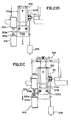
- FIGS 3(a) - 3(d) are block diagrams generally illustrating the automatic needle-suture assembly and packaging system 10 of the instant invention.
- needles are first loaded into a vibratory bowl at step 11, automatically sorted and linearly fed at step 12 to a translucent indexing conveyor at step 13, evaluated with respect to orientation and position by a vision tracking system at step 14, picked up by a robot apparatus at step 15, transferred to a precision conveyor by the robot apparatus at step 16, and finally conveyed to a load station where the needles are transferred to a multi-axis gripper located on a rotary swage dial 150 for subsequent transfer to the swaging station 200 indicated at step 17.
- a detailed explanation of the apparatus used to carry out each step will be explained in further detail hereinbelow.
- an automatic suture cutting and swaging process is taking place at the swaging station 200 shown in Figures 3(a) and 3(b) with respect to steps 19 through 30.
- Indefinite length suture material is supplied in various spools and configurations that may carry up to 5000 yards of material. This is indicated at step 19 in Figure 3(a).
- the suture material is loaded into a payoff assembly which is part of a drawing tower apparatus to be described in detail below.
- This payoff assembly includes grippers that alternately draw the suture material from the spool to enable cutting thereof.
- the material may be optionally loaded in a driven spool feed assembly with a dancer as indicated at optional step 21 to ensure that the material does not break or snap when in tension.
- the suture material While the material is being drawn, it may require extra treatment or processing. For instance, as described in detail below, it may be desirable to heat the suture material under tension at the suture tip in order to stiffen the material to facilitate the positioning thereof within the suture receiving opening of a surgical needle. Thus, at optional step 22, heat may be applied to a portion of suture material.
- the suture material is gripped by the servo grippers.
- the suture strand is drawn up the tower and positioned for insertion within the suture receiving opening of the needle for swaging.
- the multi-axis gripper positions the needle in a precisely oriented position at the swage die opening formed at the ends of two swaging dies of a swage assembly as indicated as step 26 in Figure 3(b).
- the suture strand is drawn from a king spool along a single axis of a drawing tower to register a tip thereof for insertion within the suture receiving end of the needle.
- the gripper assembly at the drawing tower inserts the tip of the suture strand within a lower funnel guide for accurate positioning within the suture receiving opening of the needle that is aligned with the suture drawing axis.
- the multi-axis gripper releases its grip on the needle placed within the swage die opening.
- the swage cylinder is activated to automatically swage the suture to the needle and to cut the indefinite length of suture strand at a predetermined length.
- the multi-axis gripper is then retracted at its station on the rotary swage dial as shown as step 30 and indexed to a pull-test station 300 at step 31 so that minimum pull-testing at step 32 or destructive pull-testing at step 33 may be performed.
- the armed needle will either be indexed by the rotary swage dial to the discharge station 400 where the armed needle will be discharged to the suture winding and packaging turret 500 if the pull-test requirements are met (as shown as step 34a in Figure 3(b)), or, will be discharged at the pull-test station if the needle fails the minimum pull-test (as shown as step 34b in Figure 3(b)).
- the destructive pull-test always renders the armed needle incapable of further processing so the needle is automatically discharged at the pull-test station 400 as indicated at step 35 in Figure 3(b).
- the automatic packaging processes are taking place about the suture wind and packaging turret 500.
- step 40 in Figure 3(c) at the package load station 400, an empty package tray is positioned on a tool nest located on the rotary suture winding turret 500.
- the empty package tray is indexed to an optional package detect station 450 for checking the presence of the loaded empty package.
- step 45 the empty package tray is indexed to the needle-suture load to package station 600.
- the empty package tray support is engageable with an elevator assembly that successively registers the package tray for sequential receipt of needles from the rotary swage dial, as indicated at step 51.
- armed needles that have passed the minimum pull-test are conveyed to a needle-suture load to package station 600 where up to eight individual armed needles are loaded into the package.
- the package tray containing the armed needles are indexed to the optional needle check station 475 for detecting missing needles.
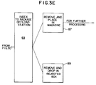
- the suture winding station 550 where the suture strands depending from the needles are first gathered into a bundle by a vacuum assembly as shown as step 61 in Figure 3(d). Then, the package tray containing the armed needles is oriented at step 64 to facilitate cooperative engagement with the winding stylus at step 67 that is extended to position the gathered suture bundle within the peripheral channel of the package tray. Next, at step 70, the package tray is rotated so the gathered suture bundle is wound around the peripheral channel. Finally, at step 73, the package tray containing armed needles is indexed to an open station 625 which may be an optional manual inspection station.
- a package cover (lid) is loaded onto a gripping device, as shown at step 77, for attachment to the package tray at the paper insert station 650.
- the package tray is indexed to the paper insert station 650 where the gripping device places the package cover onto the package tray to form a completed package.
- the completed package is indexed to the package removal station 700 where the package is either discharged for further processing, as shown in step 87, or, if the package is determined to be flawed, is discharged to a reject bin as shown at step 89.
- the needle sorting station 100 sorts, singulates, and successively conveys individual and precisely oriented surgical needles to each of four multi-axis grippers indexed thereat by the rotary swage dial assembly 150, in the following manner:
- a batch of unoriented needles of uniform size are first loaded into vibratory bowls 101a,b, automatically sorted and linearly fed by singulating devices 102a,b to each of two translucent indexing conveyors 105a,b, evaluated with respect to orientation and position by a vision tracking system (not shown), picked up by either of two robotic apparatuses 106a,b, transferred to individual engagement devices (boats) 108 located on a precision conveyor 107 by each robot apparatus, and finally conveyed to the rotary swage dial assembly where the needles are transferred to a multi-axis gripper for subsequent transfer to the swaging station 200 as will be described in further detail below.
- the next step of the needle threading and swaging process 10 involves the loading of the individual precisely oriented surgical needle 9 from the precision conveyor boat 108 onto the multi-axis gripper 155.
- the precision conveyor boat 108 is in a vertical position on conveyor 107 and carrying needle 9 in a precise orientation as shown in Figure 5.
- the needle 9 is delivered from the engagement jaws 111,112 of the conveyor boat 108 to the multi-axis gripper 155 that has been indexed to the needle sorting station 100 in opposed relation with the precision conveyor boat 108.
- gripper pin assembly 152 comprising pins 142, 146, and 148 that extend perpendicularly therefrom to engage needle 9.
- the multi-axis gripper is extended from its retracted position upon the swage dial assembly 150 in the manner described below, so that pins 146 and 148 of the gripper pin assembly penetrate a plane formed by the curvature of needle 9 positioned upon the precision conveyor boat 108 as shown in Figure 5.
- the control system 99 initiates the command for a load solenoid or similar device to open engagement jaws 111,112 of the precision conveyor boat 108 to release the needle 9 so that it is deposited between the pins 146 and 148 of the multi-axis gripper 155.
- a front view of the multi-axis gripper 155 with needle 9 positioned thereon after transfer from the precision conveyor boat 108 is illustrated in Figure 10(a).
- pin 142 is actuated from a non-engaging position to an engaging position to thereby engage the needle 9 in an oriented position as shown in Figure 10(b).
- the multi-axis gripper 155 is then retracted from its extended position and the swage dial assembly 150 is rotated to the swaging station 200 for automatic swaging of the suture to the needle 9.
- Figure 10(b) illustrates pins 142 and 144 located along the outer arcuate portion of the needle, while pin 146 supports the pin at the inner arcuate portion 8 of the needle 9.
- the barrel portion 7 of the needle 9 fits against a protruding stop 148 located on the gripper pin assembly 152 of the gripper 155 as shown in Figure 10(b).
- the location of the stop 148 may be adjusted to accommodate the engagement of different size surgical needles.
- the gripper pin assembly 152 is replaceable with other gripper pin assemblies having the stop 148 positioned to accommodate different sized surgical needles.
- the suture receiving end portion 7 of needle 9 extends below the gripper pin assembly 152 of the multi-axis gripper 155. This enables placement of the suture receiving end 7 of the needle within the swage dies of the swaging assembly as will be explained below.
- pin 142 is spring loaded and is retractable within guide 147 to release its grip of needle 9 when a needle is being transferred thereto or, when automatic swaging and pull-testing occurs. Retraction of pin 142 is activated by depressing plunger 149 by a suitable push rod or cam 143 as shown in the Figures. Pin 142 is biased back into the needle engaging position as shown in Figure 10(b) by retracting the push rod or cam 143.
- the rotatable swage dial assembly 150 includes four multi-axis gripper stations where simultaneous needle operations are performed.
- the swage dial assembly 150 includes a swage plate 110 having four multi-axis gripper stations 145a, 145b, 145c, 145d spaced equally thereon.
- the swage plate 110 is rotatably mounted at a central hub 109 and operable to rotate under the control of a control system computer 99.
- a reciprocating carriage is provided at each multi-axis gripper station of the swage dial assembly 150.
- multi-axis gripper station 145a includes reciprocating carriage 151a
- station 145b includes reciprocating carriage 151b
- station 145c includes reciprocating carriage 151c
- station 145d includes reciprocating carriage 151d.
- each reciprocating carriage 151a,b,c,d and the multi-axis gripper 155 connected thereto is movable from a retracted position to an extended position.
- the needle 9 may be conveyed to a different station as the swage dial rotates; when the gripper 155 is in the extended position as shown in Figure 7(b), the needle is in one of the active stations, such as the automatic swaging station.
- the swaging station and the automatic pull-test station are both described in further detail in respective copending patent applications (attorney docket No. 8937) and (attorney docket No. 8923) assigned to the same assignee of the present invention.
- each cam follower 165a(b,c,d) is mounted to a cam slide 164 at one end of the reciprocating carriage 151, and the multi-axis gripper 155 is connected to the cam slide 164 at the other end.
- Cam slide 164 is slidable within stationary guides 166,167 and is adapted for reciprocal movement when the cam follower 165 is actuated.
- cam follower 165 is a roller that fits within cam tracks of a rotatable cam dial assembly 120.
- Cam dial assembly 120 is shown in Figure 8(a) as comprising a cam dial plate 125 having four cam tracks 160a,b,c, and 160d which correspond to a multi-axis gripper stations 145a,b,c, and 145d, respectively.
- Each cam follower 165 is positioned within each respective cam track at each station for movement therein.
- cam follower 165a is positioned within cam track 160a
- cam follower 165c is positioned within cam track 160c.
- cam dial 125 is positioned above swage dial 110 and mounted coaxial therewith. The cam dial 125 is rotatable about a central shaft 199 and controlled by a separate rotary indexing transmission (not shown) so that it may rotate separately from the swage dial plate 110.
- Figure 8(a) shows cam follower 165a in a first retracted position within the cam track 160a.
- the cam dial plate 125 is rotated in the clockwise direction with respect to the swage dial plate 110, as indicated by the arrow in Figure 8(a), for approximately 45 - 55 degrees, forcing cam follower 165a in its cam track 160a to move toward the periphery of the dial as shown in Figure 8(b).
- cam slide 164, reciprocating carriage 151a, and the multi-axis gripper 155 move to the extended position as shown in Figure 7(b) and discussed above.
- the cam dial plate 125 is rotated in the counter clockwise direction with respect to the swage dial plate 110 for approximately 45 - 55 degrees, forcing cam follower 165a in its respective cam track 160a to move back to its retracted position ( Figure 8(a)). Consequently, the cam slide 164, reciprocating carriage 151a, and the multi-axis gripper 155 move to the retracted position as shown in Figure 7(a) and discussed above.
- each multi-axis gripper 155 is either extended or retracted in its respective cam track.
- the system is designed so that all processes performed at each station occur simultaneously and for approximately the same duration of time when the multi-axis grippers are in their extended position, for e.g., for needle pick-up, for needle swaging, or, for needle pull-testing.
- the timing of the system is operated under the control system, a detailed description of which can be found in copending patent application (attorney docket No. 8927), assigned to the same assignee of the present invention.
- both swage dial plate 110 and cam dial plate 125 are rotated together for approximately 90 degrees to position each multi-axis gripper at the next station.
- the gripper 155 that had received the needle at station 100 is now indexed to the position corresponding to station 200 for swaging a suture thereto.
- the cam dial plate 125 and the swage dial plate 110 are simultaneously rotated counterclockwise so that the armed needle at station 200 is indexed to the pull testing station 300 for pull-testing thereof.
- the operations performed concurrently at each station about the swage dial increases throughput to provide an output of pull-tested armed surgical needles at a rate of approximately 60 per minute in the preferred embodiment.
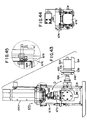
- the automatic swaging station 200 of the needle threading and swaging system 10 is where the suture of indefinite length is drawn, cut, and inserted within the suture receiving end of a surgical needle for swaging thereof.
- the indefinite length of suture material is loaded at one end of the payoff assembly.
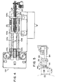
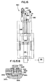
- the payoff assembly is embodied as a drawing tower 220 shown in Figure 12(a).
- the drawing tower 220 comprises left side rail 222 and right side rail 224 both mounted on suitable mounting block 225 and defining a drawing bed for drawing an indefinite length of suture material along a drawing axis therebetween.
- the first gripper means or right gripper 232 reciprocates up and down along right guide rod 228 while the second gripper means or left gripper 230 reciprocates up and down the left guide rod 226.
- Each of the grippers 230,232 grip the suture material that is fed from a spool through pulley 235 located at the bottom of the drawing tower 220, and carries the material to the upper end of the tower.
- the right gripper 232 is mounted on right gripper carrier 233 for vertical movement along right guide rod 228, and the left gripper 230 is mounted on left gripper carrier 231 for vertical movement along left guide rod 226 as shown in Figure 12(a).
- Figure 11 illustrates a gripper 232 (and 230) having a gripper arm drive 261 that is pneumatically operated to drive pair of retractable gripper arms 265a, 265b toward each other to a suture gripping position, or, away from each other to an open position.
- Each retractable gripper arm is provided with a non-metallic pad 266a, 266b for gripping the suture material 255 at a free end thereof when actuated to the gripping position.
- gripper arms 265a,265b are retracted approximately 180 degrees apart in the direction indicated by the arrows of Figure 11 to the open position.
- the gripper arms 265a', 265b' do not interfere with the motion of the other vertically moving gripper as it reciprocates along the respective left or right rod, nor will it interfere with the cutter assembly 280 that cuts the strand to a predetermined length as will be explained below in view of Figure 14.
- the retractable nature of the grippers and of the cutting assembly enables single drawing axis operation.
- each gripper carrier and gripper thereof is designed to advance vertically along the respective left and right rods.
- the right gripper 232 and gripper carrier 233 is driven by right servo motor 238 which is mounted to the right side rail 224 by right motor mounting bracket 239.
- the left gripper 230 and gripper carrier 231 is driven by left servo motor 236 which is mounted to the left side rail 222 by left motor mounting bracket 237.
- both left and right servo motors are interfaced with and controlled by the control system computer 99.
- right servo motor 238 drives timing belt 243 which consequently enables vertical positioning of right gripper carrier 233 along right rod 228, while the left servo motor 236 drives timing belt 241 which consequently enables vertical positioning of left gripper carrier 231 along left rod 226.
- timing belt 243 is clamped to its respective gripper carrier 233 by a timing belt clamp 268 located on the back of the gripper carrier.
- a similar timing belt clamp (not shown) is provided on gripper carrier 231 for clamping timing belt 241 to enable vertical movement of gripper 230.
- Figure 12(a) shows timing belt 241 engaging upper left pulley 245 and lower left pulley 246 as well as idler pulleys 247,248 which are part of tensioner block 244 that adjusts the tension of the timing belt 241 and consequently of left gripper carrier 231.
- Figure 12(a) shows timing belt 243 engaging upper right pulley 251 and lower left pulley 252 as well as idler pulleys 253,254 which are part of tensioner block 245 that adjusts the tension of the timing belt 243 and consequently of right gripper carrier 233.
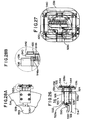
- FIG 12(a) shows the tip and cut carrier 180 positioned along shafts 204 and 205 which are located parallel to respective left and right rods 226,228.
- Tip and cut carrier 180 provides the support for tipping assembly 290 that applies heat to a specific location of the suture material, and also provides support for the cutter assembly 280 that cuts the suture material.
- vertical movement of the tip and cut carrier 180 is accomplished by cranking handwheel 208 shown in Figure 12(b).
- Other embodiments may implement a computer controlled servo motor to vertically register the tip and cut carrier 180 prior to cutting the material.
- cranking handwheel 208 actuates a gearbox 213 that rotates chain drive sprocket 214.
- the gearbox 213 is mounted on a gearbox mounting bracket 122 which, in turn, is mounted to frame member 299.
- a cable chain 215 is engaged with chain drive sprocket 214 to actuate movement of the tip and cut carrier 180 as shown in Figure 12(b).
- the cable chain 215 also engages chain idler sprockets 218 and 219 which are rotatably mounted to upper tensioner pulley bracket 221 and lower tensioner pulley bracket 223, respectively.
- the vertical positioning of tensioner pulley brackets 221,223 may be adjusted to vary the slack in cable chain 215.
- Cable chain 215 also engages chain idler sprockets 227 and 229 which are suitably mounted on left side rail 222. As shown in Figure 12(a), the back 211 of tip and cut carrier 180 is clamped to cable chain 215.
- Both the stroke of the grippers 230,232 and the positioning of the tip and cut carrier 180 along drawing tower 220 dictates the length of the material that will be cut.
- proximity sensors 273,274, and 275 are positioned vertically at different heights along the drawing tower 220 to enable predetermination of the length of suture material to be cut.
- the locations of the proximity sensors 273,274, and 275 sense the positioning of the tip and cut assembly 180 as controlled by handcrank 208 in order to notify the control system 99 to change the reciprocating travel of grippers 230,232.
- proximity sensor 270 is mounted at a position along the right side rail 224 to verify that right gripper 232 has reached a desired position at the upper end of the tower 220 and notify the control system 99 accordingly.
- a proximity sensor (not shown) is mounted at the desired height along the left side rail 222 to verify that left gripper 230 has reached its desired position at the upper end of the drawing tower 220.
- the suture material 255 is first manually threaded through eyelet 256 and through optional knot detector 257 which senses any sudden change in the thickness of the suture material as shown in Fig. 13. Detection of a knot in suture material 255 will trigger the control system 99 to discard the cut strand of material at a subsequent operation.
- the suture material may be threaded within a tensioning (or dancer) assembly 259 which comprises a plurality of vertically spaced apart cones 223 each of which may be positioned laterally to increase or decrease the tension of the suture strand 255 as shown generally in Figure 13.
- the suture material 255 is then advanced over pulleys 235a and 235b located at the bottom of the drawing tower 220, and around pulley 212 which is mounted on the lower portion of tip and cut carrier 180 that is illustrated near the center of the tower as shown in Figure 12(a). Note that the lower threading pulley 235b, guide pulley 212, left gripper 230 and right gripper 232 are vertically aligned so that the cutter assembly 280 will always cut horizontally across the strand of material as will be discussed in detail below.
- the right servo motor 238 is enabled to drive the lead (right) gripper vertically along right rod 228 to register the tip of the indefinite length suture strand 255 for positioning within the suture receiving opening 7 of a precisely oriented surgical needle shown engaged by the multi-axis gripper 155 at the swaging assembly 390 located at the top of the drawing tower 220 as shown in Figure 12(a).
- the lead gripper servomotor advances the lead gripper for a long stroke distance, which may range from 12 inches to 36 inches depending upon the length of said suture strand desired, but is 16.1 inches in the preferred embodiment.
- the long stroke moves gripper 232 from a home position just above the tip and cut carrier 180 and below the cutter assembly 280, to the position slightly below swaging assembly 390 as shown in Figure 12(a).
- the other servomotor positions the bottom gripper, for e.g., left gripper 230, along left rod 226 at the home position preferably above the tip and cut carrier 180 and below the position of the cutter assembly 280 as shown in Figure 12(a).
- the lead gripper is gripping the material 255 at all times during the long stroke, while the bottom gripper is in its open position and not gripping.
- the process of advancing suture material 255 by alternating grippers at each cycle eliminates the recycle or return time for retaining the gripper to the original position. This makes faster machine speeds and hence, higher production rates possible.
- the lead gripper 232 again advances the suture material 255 for a short stroke distance of about 1.9 inches, so that the tipped end 258 will advance precisely within the suture receiving opening 7 of needle 9 for a swaging operation to take place at the swaging assembly 390.
- tipping assembly 290 As the tipped end 258 of the suture material is advanced during the short stroke distance, a portion of the material 255 that has been heated by tipping assembly 290, (explained hereinbelow), advances vertically to a position just above the home position of the left gripper 230 and adjacent the cutter assembly 280.
- the left gripper 230 (lower gripper) is actuated to grip the material 255 at or below the tipped portion 278 i.e., the portion of the suture material heated by tipping assembly 290 as shown in Figure 12(a), and the cutter assembly 280 is actuated to cut the tipped portion 278 of the suture material 255 so that the left gripper 230 is now gripping an indefinite length suture strand 255 having a tipped end 258.
- the top or right gripper 232 is actuated to release its grip on the definite length suture material.
- the top gripper Immediately after advancing the long stroke distance and prior to advancing the short-stroke distance, the top gripper is temporarily halted so that a portion of the suture material 255 may be heated (tipped). Heating of the suture under tension and the subsequent cooling thereof will stiffen the material and aid in the positioning and subsequent swaging of the tip of the material within the confines of the surgical needle.
- the operation of the tipping assembly 290 mounted on tip and cut carrier 180 will now be explained as follows:
- the tipping assembly 290 is essentially an oven comprising a heat exchanger unit 295 that heats the air in the heater cavity 296.
- a pulse of incoming air is provided to the heat exchanger input 297, the heated air is displaced and it provides a pulse of heated air to a vertical cylindrical cavity 291 as shown in Figure 12(a).
- the heated air is forced through horizontal orifice 294 for a predetermined duration so that the length of suture material 255 suspended in tension through vertical cavity 291 will be heated.
- the control system computer 99 controls the duration of the heat pulse so that the material is adequately heated and will have sufficient time to cool before the cutting operation.
- the tipping assembly 290 is positioned slightly below the bottom or left gripper 230. As mentioned above, this is required so that when the suture material 255 is advanced the short stroke distance, the tipped portion 278 of material 255 will advance a corresponding distance so that it may be cut by cutter assembly 280. This ensures that the bottom gripper, e.g., left gripper 230, will grip the material having a new tipped end 258 for the next suture draw/insert cycle.
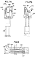
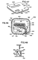
- FIGs 16 - 17(b) illustrate in detail the cutter assembly 280 which is suitably mounted to the tip and cut assembly 180 as shown in Figure 12(a).
- the cutter assembly comprises overcenter linkage 282 having a link arm 283 pivotally connected at one end thereof.
- a pivotal locator arm 285 is fixedly connected to link arm 283 at a second end thereof and is illustrated in Figure 24 as substantially transverse thereto.
- the other end of locator arm 285 is pivotally connected to a stationary guide mechanism 286.
- all pivotal linkages described herein are simple pin linkages, the actuation of which creates the dwell moment for cutting the suture strand and obviates the need for complicated cam, slots, and sliding mechanisms.
- the stationary guide 286 is located in a plane perpendicular to the drawing axis of the suspended strand of material 255, and is located a distance from the strand approximately equivalent to the length of locator arm 285.
- overcenter linkage 282, locator arm 285, and cutting blade 289 all lie in planes perpendicular to the drawing axis of the strand of material 255.
- a retractable ball slide 288 is mounted on the stationary guide 286 and coupled to overcenter linkage 282 for moving the overcenter linkage and blade 289 along the stationary guide 286 in the direction indicated by arrow "A" in Figure 16 from a cutting position to a retracted position shown in Figure 17(a).
- the locator arm 285 is pivoted away from the strand 255 and the blade 289 is retracted.
- pneumatic air cylinder 281 enables reciprocating movement of the ball slide 288 along stationary guide 286 as shown in Figure 16.
- the retractable ball slide 288 reciprocates in the direction toward the strand 255 indicated by arrow "B" in Figure 17(a) to bring the overcenter linkage 282, cutting blade 289 and locator arm 285 to the cutting position shown in Figure 17(b).
- the link arm 283 translates the movement of the ball slide 288 into pivotal movement of the locator arm 285.
- Locator arm 285 is provided with a V-shaped support notch 287 which functions to engage and position the strand of material 255 to be cut as the arm is pivoted into the cutting position.
- the V-shaped notch also functions to support the strand on two sides of the strand 55 while it is being horizontally cut on a third side.
- the cutting blade 289 of cutter assembly 280 is fixedly mounted to reciprocating ball slide 288 at a slight angle relative thereto and in a plane parallel with that of the locator arm 285.
- a single action by the pneumatic air cylinder 281 will enable movement of the reciprocating ball slide 288 along stationary guide 286.
- This consequently enables pivoting of locator arm 285 from its retracted position ( Figure 17(a)), so that V-shaped notch 287 supports the strand 255 at two sides thereof while a third side of the strand bears upon the cutting edge of blade 289 as the blade moves towards the supported strand 255 traversing the drawing axis thereof.
- the strand 255 is cut in a dwell moment of the locator arm after the locator arm 285 has pivoted in the direction toward the blade 289 to the cutting position shown in Figure 17(b).
- the blade 289 slices the strand of material while it is held stationary by locator arm 285 by virtue of the angled orientation of the blade with respect to the axis of reciprocation illustrated in Figures 17(a) and 17(b).
- the slice ratio is 1:1, with the blade 289 angled at approximately 45 degrees relative to the axis of reciprocation, so that the strand 255 is cut an amount equivalent to the distance the blade 289 traverses the drawing axis.
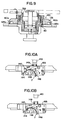
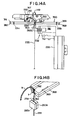
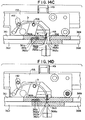
- Figures 14(a) - 14(g) illustrate the multi-axis needle gripper 155 and swaging and suture alignment dies shown in various stages of the suture insertion and needle swaging sequence. This sequence, and the interaction of the dies in relation to each other, the needle, and the insertion of the suture, accomplish the insert and swage function with minimal parts and simple motions.
- the multi-axis gripper 155 is radially extended from the swage dial in the manner described above to position the suture receiving end 7 of needle 9 between the funnel shaped die opening formed at the ends of two swage dies 361,369 as shown in Figure 14(a) and the partial perspective view of Figure 14(b).
- swage die 361 is fixed in position and swage die 369 is movable laterally toward the fixed swage die 361, as indicated by the arrow, to accomplish swaging of the suture receiving end of a needle placed therebetween.
- a funnel shaped die opening 392 having an exit diameter slightly larger than the diameter of the suture receiving end 7 of the needle is formed when the two swage dies 361,363 are positioned adjacent each other as shown in Figures 14(e) through 14(f).
- the ends of each of the swage dies 361,369 are provided with recesses 321,322 respectively, so that the metal deformation that occurs as a result of the swaging of the needle 9, does not result in metal flash or spurs at the suture receiving end 7 of the needle.
- different sets of swage dies may be provided, depending upon the size (diameters) of the needles and sutures to be swaged.
- the movable swage die 369 is temporarily moved apart.
- swage die 369 is moved apart from the fixed swage die 361 by actuating air cylinder 395 to provide a force upon cylinder rod 393 to enable swage die operating lever 397 to pivot about screw 394 and pull moveable swage die 368 a predetermined distance away from the fixed swage die 361.
- lever 397 is biased by spring 364 so that the movable swage die 369 will return toward the fixed swage die by the spring restoring force when the pressure provided by the air cylinder 395 is terminated.
- Figure 14(c) shows die 361 in its fixed position, and moveable die 369 in its spaced apart position prior to receiving the surgical needle 9 presented by multi-axis gripper 155.
- Suture alignment die 362, containing suture guide funnel half 362b, is positioned under swage die 361, and free to slide laterally within limits.
- Alignment die 362 has a tang 362a that protrudes into cavity 361a formed within swage die 420.
- Compression spring 361c bears against the back wall of cavity 361a and tang 362a such that funnel die 362 slides forward until it is constrained by cavity wall 361b.
- Suture alignment die 368 containing funnel half 363, is fastened to swage die 369 by suitable fastening means, described in detail below, and travels with it to the open position shown.
- the multi-axis gripper 155 is extended to position the suture receiving end 7 of needle 9 within the opening 392 as shown in Figure 14(c) and Figure 15(a).
- the swage die 369, and suture alignment die 368 are moved toward needle 9 with the resilient spring force present in spring 364 ( Figure 15(a)) that is sufficient to enable the die 369 to grip and locate the suture receiving end 7 precisely against fixed swage die 361 without deforming the cavity of the suture receiving opening 7 formed therein.
- needle retaining pin 142 in multi-axis gripper 155 is raised by downward external force on plunger 149, as described above, thereby releasing the needle so that its position is determined by the grip of swaging dies 361 and 369.
- the motion of dies 368 and 369 cause the face 368a of suture alignment die 368 to come in contact with the corresponding face 362c of suture alignment die 362.
- the resilient force causing this motion is forceful enough to compress spring 361c, and move funnel die 362 to the left, such that tang 362a is no longer in contact with cavity wall 361b.
- Dimensioning of dies 369 and 368 is such that this motion results in the formation of two funnel halves 362b and 363 defining a smooth conical shape that is coaxial with the suture receiving end 7 of needle 9.
- Figure 14(d) shows the suture receiving end 7 being gripped by the swage dies 361,369 prior to suture insertion.
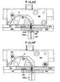
- the exit diameter of the conically shaped funnel guide formed of funnel halves 362b and 363 is preferably equal to or greater than the diameter of the suture tipped end 258 and smaller than the diameter of the suture receiving end 7 of the needle 9, as shown in Figure 14(e), so that the tipped end 258 of the suture strand may be easily inserted therein.
- Figure 14(e) shows suture gripper 265a moved vertically to the insertion position, which causes stiffened suture end 258 to enter funnel 362b and 363, and be guided into the suture receiving cavity 7 of needle 9 axially aligned therewith.
- the automatic swaging of the suture receiving cavity occurs.
- a pneumatic air cylinder 365 provides air pressure to actuate cam 375 that bears on lever 397 to thrust movable swage die 369 toward the fixed swage die to accomplish the swaging of the suture receiving end of the needle placed therebetween. Air pressure is supplied to the swage cylinder 365 via ports 366,367 under the control of the control system computer 99.
- Figure 14(f) shows the completed swage stroke.
- the swage die 369 has been driven to a fixed stop by the swage cylinder, which exerted sufficient force to deform the suture receiving end 7 of needle 9.
- suture alignment die 368 further displaces funnel die 362, causing additional compression of spring 361c.
- the moveable swage die 369 comes to an automatic stop by a swage stop mechanism herein described.
- movable swage die 369 and suture alignment die 368 are mechanically held coincident to each other by shouldered post 369a, the smaller diameter of which is a light press fit into the mating hold in die 369.
- Cap screw 369c, with washer 369b retain the post in die 369.
- the larger diameter of post 369a, below die 369, extends through a light press fit hole in funnel die 368, so that the right hand swage and funnel dies are linked to move together laterally during the swaging cycle.
- the lower portion of shouldered post 369a extends through funnel die 368, into groove 390b, which is cross milled into swage assembly frame 390a.
- the swage cylinder drives this die assembly to the left until it is positively stopped by the lower portion of post 369a striking wall 390c of groove 390b. This stalls air cylinder 365, so that the stroke of the moveable right hand die assembly shown is always the same for repeating cycles of the machine.
- both swage dies 361,369 may be movable towards each other to accomplish swaging.
- an adjustable swage stop mechanism for changing the swage stroke distance of one of the movable dies may be provided to further control the swaging pressure applied to the suture receiving opening and obviate the need for a fine-tune positioning adjustment for a fixed swage die.
- a needle fence assembly 398 is provided to ensure that the needle 39 does not tip or become misaligned when the end 37 of the relaxed needle is positioned between the swage dies.
- the needle fence assembly 398 comprises a needle fence plate 399 whose distance from the tapered swage die opening 392 is adjustable depending upon the size of the surgical needle to be swaged.
- the degree of swage compression imparted on the needle, and resulting strength of grip by the needle on the suture is adjusted by precise positioning of the fixed die 361.
- servomotor 345 drives pulley 344 via timing belt 461, which rotates the swage adjust screw 347.
- the pitch of the swage adjust screw 347 is selected to move sliding wedge 348 a small distance.
- the swage die 361 has a complementary ramp angle 343 at the opposite end which bears on the wedge 348 to retract or advance the position of the swage die 361 a precise distance proportional to the movement of the sliding wedge.
- the rotation of the swage adjust screw 347 and motion of the sliding wedge 348 results in transverse movement of the swage die 361 to thereby finely adjust its fixed position.
- the position of the fixed die 361 may be moved further away from the suture drawing axis so as to provide the desired amount of deformation when the swaging pressure is applied to the needle by the movable swage die 369.
- control system computer 99 will send the appropriate signals to automatically direct the servomotor 345 to adjust the position of the swage adjust screw 347, and hence, the position of the fixed die 361, in accordance with the pull-out test values of the needle-suture bond as measured by automatic pull-test system as explained in further detail below.
- appropriate control signals may be generated to direct the servomotor 345 to adjust the rotational position of the swage adjust screw 347 in accordance with stored statistical results of the pull-testing occurring at the pull-test station.
- Automatic pull-testing of the armed needle is desirable to ensure that the upstream swaging dies are optimally positioned to avoid over-swaging the needle-suture bond and hence, preventing the likelihood of clip-off, and, to avoid under-swaging the needle-suture bond to prevent the chance of pull-out.
- the left gripper 230 secures the suture strand, and the suture material 255 is cut by the cutter assembly 280 in the manner described above and as indicated in step 30 in Figure 3(b).
- the cutter assembly 280 is positioned slightly above the left gripper 230 so that the indefinite length suture strand 255 will be gripped when the swaged strand is cut.
- the left gripper 230 is now gripping the suture material 255 with a tipped end 258 and it now becomes the lead gripper.
- a vacuum air flow is energized to pull the strand of material 255 toward the nylon screen 357 to facilitate the cutting of the material thereof.
- the tail end of the length of suture material that had been swaged to the surgical needle is sucked into a large vacuum pipe 358, that is connected to a vacuum assembly (not shown) by vacuum hose 359 as shown in Figure 12(a).
- the vacuum created in vacuum pipe 358 exerts a mild tension in the strand of material to keep the tail end from entanglement or coming into contact with the machinery. However, it is mild enough to allow the strand to be pulled out of the pipe 275 as the armed needle is indexed for further downstream processes.
- the movable die 369 is again retracted by air cylinder 365 and the pin 142 of the multi-axis gripper 155 is actuated to engage the armed needle in the manner described above. Subsequently, the multi-axis gripper 155 is retracted (step 30) to its position along the swage dial 150 for subsequent indexing to the pull-test station 300 for further processing (step 31).
- the cycle continues at the swaging station with the new lead gripper vertically drawing the material 255 along the height of the drawing tower 220 to position the next strand to be cut for insertion within the surgical needle.
- the process of advancing suture material 255 by alternating grippers at each cycle eliminates the recycle or return time for retaining the gripper to the original position.
- a test of the strength of the swaging bond of the armed needle indexed at the automatic pull-test station 300 may be performed as described in detail below and in further detail in copending patent application (attorney docket No. 8923) assigned to the same assignee of the present invention and incorporated by reference herein.
- Automatic pull-testing of the armed needle is desirable to ensure that suture pull-test requirements are met. Specifically, as described in detail below, either a minimum pull-test, indicated as step 32 in Figure 3(b), or, a destructive pull-test, indicated as step 33 in Figure 3(b) is being performed at the pull-test station 300.
- the automatic pull-test assembly 300 for accomplishing automatic pull-testing of an armed surgical needle is shown generally in Figures 20 through 21(c).
- the automatic pull-test assembly 300 generally comprises a load cell mounting assembly 330 for mounting a load cell 335 which functions to receive the armed needle 9 from the multi-axis gripper 155 which is indexed thereto as shown in Figures 20 and 21(a).
- a needle release assembly 315 is provided for relaxing the armed needle from the grip of the multi-axis gripper 155.
- Pull-test fence assembly 340 is provided to prevent the armed needle 9 from tipping over or becoming misaligned when the armed needle is relaxed.
- Suture gripping assembly 370 containing retractable gripper arms 325a,b for gripping the suture 255 during the pull-tests, and which are connected to the weighted slide block assembly 372 for performing the pull-test is provided as shown in Figure 20. A detailed description of each of these assemblies and their interaction will be explained in detail hereinbelow.
- an armed surgical needle 9 is retained by a multi-axis gripper 155 and, in the manner described above, is indexed to the automatic pull test station 300 by the rotary swage dial 150 partially illustrated in the Figure 20.
- the multi-axis gripper is extended from the swage dial 150 so that the end portion 7 of needle 9 is positioned above a corresponding receiving blade 336 of the load cell 335 as shown in Figure 21(a).
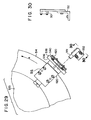
- FIG 22 illustrates a top view of the load cell mounting assembly 330 with load cell 335 mounted thereon.
- load cell 335 has mounted thereon four (4) thin needle supporting blades 336a,b,c,d for supporting the suture receiving end portion 7 of various size surgical needles with the suture material 255 depending therefrom.
- load cell needle supporting blade 336a labelled "1/0” accommodates a larger sutures having a diameter of approximately 0.017 +/- 0.001 inches
- load cell needle supporting blade 336b labelled “2/0” accommodates sutures having a diameter of approximately 0.014 +/- 0.001 inches
- load cell needle supporting blade 336c labelled “3/0” accommodates sutures having a diameter of approximately 0.011 +/- 0.001 inches
- load cell needle supporting blade 336d labelled "4/0” accommodates a smaller suture with a diameter of approximately 0.009 +/- 0.001 inches in the preferred embodiment.
- the appropriate needle supporting blade 336a,b,c,d will be positioned to receive the needle from the multi-axis gripper.
- Knob 339 located centrally on top of the load cell 335 may be manually operated to rotate the load cell and position the correct sized suture receiving blade prior to carrying out automatic pull-testing. Additionally, the load cell 335 may be laterally positioned by moving slide handle 338 and consequently load cell platter 337 towards or away from the suture needle indicated by the arrow in Figure 22.
- FIG. 23 is a front cross sectional view illustrating the suture receiving end portion 7 of needle 9 resting upon the needle supporting blade 336b with the suture strand 255 threaded between the suture receiving guide 334.
- Non-destructive pull testing of the armed surgical needle 9 is accomplished as follows:
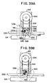
- gripper arms 325a,b of suture gripping assembly 370 are extended from a retracted position to grip the suture strand 255 slightly below the needle supporting blade 336 of load cell 335 as shown in Fig. 30.
- a gripper actuator 372a is provided for opening and closing gripper arms 325a,b, as shown in Fig. 20, and is controlled by a control system program resident in control system computer 99 as explained in further detail in copending patent application (attorney docket No. 8927) assigned to the same assignee of the present invention.
- Figures 20 and 21(a) illustrate the slide block assembly 372 that is composed of slide rods 372b,c that are connected to a lower slide block 372d.
- Slide block 372d includes a slide finger 372e upon which air cylinder piston rods 374a and 379a, of respective air cylinders 374, 379, apply respective upward and downward forces depending upon the type of pull-test that is to be performed.
- piston rod 374a is shown in an extended position providing an upward force that supports slide finger 372e and consequently maintains slide block 372d of slide assembly 372 at a fixed vertical position.
- Slide block 372d is counterweighted to a net downward weight of 2 to 5 ounces by appropriately sized counterweight 376 that acts through cable 373, around pulley 377, and through attachment point 372h. This counterweight 376 acts to pull upward on slide block 372d at the attachment point 372h.
- piston rod 374a of air cylinder 374 mounted on the mechanism frame 371 and controlled by system computer 99, is retracted from its extended position (Fig. 21(a)) supporting the slide finger 372e as shown in dashed line in Fig. 21(b), by reversing its air supply (not shown), to the position shown in the figure.
- the piston rod 374a is retracted to remove the upward force on slide finger 372e, as shown in the Figure 21(b), to thereby impose the counterbalanced net weight of 2 to 5 ounces of slide block 372d on the swage attachment means of suture 255 in needle 9, in the direction of arrow "A".
- the slide block mount 371 is positioned parallel to the axis of the suture 255 depending from the needle 9, and is located a distance away from the suture 255 corresponding to the length of the gripper arms 325a,b.
- the needle release assembly 315 is actuated to enable multi-axis gripper 155 to disengage its grip on the armed needle 9. Releasing the armed needle from the grip of the gripper 155 is necessary to ensure that it is firmly positioned on the load cell needle supporting blade 336. Moreover, to provide an accurate pull-test, the needle must be released so that there is no existing upward force that would cause false results.
- needle release assembly 315 comprises needle release solenoid 324 that is actuated to extend pusher 326 into pivotal lever arm 327. Pivotal lever arm 327 pivots about pin 328 to depress plunger 149 of the multi-axis gripper 155 at one end 329 thereof. As shown in Fig. 21(a), depressing plunger 149 enables pin 142 to retract within pin guide 147 to release the armed needle 9 engaged thereby. Further details of the operation of the multi-axis gripper 155 can be found in the above-mentioned copending patent application (attorney docket 8937).
- a needle fence assembly 340 is provided.
- the needle fence assembly 340 includes vertical fence plate 342 which can be adjusted to lie flush against the gripper 155 to retain the armed needle in an upright position. Adjusting the lateral positioning of the vertical fence plate 342 is accomplished by moving slide handle 343 for an appropriate distance as shown in Fig. 20.
- the configuration of the face of the vertical needle fence plate 342 (not shown) may be changed to accommodate the configurations of different size needles.
- the controlled release of the minimum pull-test is of short duration, preferably ranging in milliseconds. If the test is successful, i.e., the suture meets the minimum pull-test requirements, the needle is re-gripped by the multi-axis gripper 155 by deactuating the needle release solenoid 324 (Fig. 20) which releases the force on plunger 149. The suture grippers 325a,b are then retracted to their open position to release their grip on the suture 255 as controlled by the control system. Subsequently, the multi-axis gripper 155 is retracted and the rotary swage dial is rotated to convey the armed needle downstream for further processing.
- the control system computer 99 is flagged so that the disarmed needle 39 will be ejected at the pull-test station.
- the dislodged suture strand 255 will be drawn into a vacuum assembly (not shown) and the needle 9 will be ejected by a needle stripper assembly 380 shown generally in Fig. 21(a) and in detail in Fig. 24.
- needle stripper solenoid 382 will be actuated by a control signal output from the control system computer 99 to extend needle stripper blade 385 mounted on a slide block 383.
- the needle stripper blade 385 is shown in Fig. 20 located next to the needle 9.
- the needle stripper blade 385 is extended to remove the needle from the gripper.
- the needle will fall and be collected by appropriate collection means (not shown) located at the pull-test station.
- the slide assembly 372 and retracted gripper arms 325a,b are pushed back up the slide mount 371 to their unloaded position by an appropriate upward force supplied by the air cylinder 374 and piston rod 374a as controlled by the control system computer 99.
- another flag may be sent for storage to the control system computer that indicates that the pull-test performed on the particular needle 9 was successful and that the armed needle may be conveyed downstream for packaging thereof.
- the load cell 335 and the needle support blades 336a,b,c,d thereof comprise a piezoelectric transducer that measures the force applied by the suture gripping assembly to the needle-suture assembly 9.
- the transducer load cell 335 may be interfaced with the control system computer 99 by conventional means as shown in Figs. 20 and 22, and, in the preferred embodiment, is a 1000 gram transducer manufactured by Techniques Co. (Model No. GS-1K).
- the forces applied to the suture 9 and measured by the load cell transducer 335 during the destructive pull-testing may be stored for statistical purposes or for real-time monitoring during a swage die setup routine that may take place when a new batch of surgical needles are to be swaged. For instance, if the destructive pull-tests fail and the forces measured by the transducer are determined to be at the low end of a predetermined range, then the control system computer 99 will acknowledge this and send appropriate signals to the upstream swaging assembly (not shown) causing a fixed swaging die to be advanced an incremental amount toward the moveable swage die, resulting in subsequent swages being stronger. Likewise, if the destructive pull-test passes, i.e., the forces measured by the transducer are determined to be above the minimum and below an upper limit, then no die adjustment need be made.
- the automatic pull-test assembly 300 is used to perform a minimum pull-test upon every armed surgical needle indexed thereto prior to automatic packaging thereof.
- a destructive pull-testing of the armed surgical needle is performed at every nth needle indexed thereto.
- the purpose of performing a destructive pull-test is to set the swage dies located at the upstream swaging station for correct maximum swage pull-out value.
- This is by necessity a destructive test, and the test frequency, which is programmable, is set high enough to maintain control of the operation, but low enough to avoid excessive product waste. In the preferred embodiment, this frequency is set at every 50th needle, but could be every 75th or 100th needle.
- Another purpose of the destructive pull test is to aid in installing a new swage die set during a changeover procedure, which is a procedure that is used to prepare the needle sorting and swaging apparatuses (swage dies) for processing a new batch of needles when they are of a different size from a previously processed batch.
- the pull-test apparatus is programmed for 100% destructive test of a swaged needle, while the swaging assembly is operating and feeding the armed needles to the pull-test station.
- the die adjustment system at the upstream swaging assembly will receive a signal from the transducer load cell 335, at each machine cycle, and quickly perform a correct adjustment of the swage dies.
- Destructive test pull-out values are recorded in the system computer 99 and are used to compute statistical process control information which is fed back to the machine operator through display screens.
- Destructive pull testing of the armed surgical needle 9 is accomplished similarly as described herein above with respect to the minimum pull test. However, the fundamental difference is that a fixed mechanical stroke that is great enough to pull the suture out of the needle replaces the minimum 2 to 5 ounce force of the minimum pull test.
- piston rod 379a of second air cylinder 379 located opposite air cylinder 374 is programmed to provide a fixed stroke against slide finger 372e from a non-actuating position shown in Fig. 21(a) to the position shown in Fig. 21(c). This results in the vertical displacement of slide finger 372e from a position shown by the dashed line to a position shown by the solid line. This further results in a downward force upon slide block 372d, which, through slide rods 372b and c, moves slide assembly 372, including grippers 325a,b and suture 255, in the direction of the arrow "B" as shown in Fig. 21(c). Air pressure to cylinder 379 is set high enough to always pull suture 255 out of needle 9. This stroke is limited by the top portion 372j of slide assembly 372 striking the top of stationary block 371.
- the force necessary to accomplish the destructive pull-test is measured by the piezoelectric load cell transducer 335 as discussed above. If it is determined by the process control algorithm (not shown) that the destructive pull-test forces as measured by the transducer load cell are lower than a predetermined range of pull-test values, the control system computer 90 will send out appropriate control signals to increase the swaging die stroke applied when swaging the suture to the needle at the upstream swaging station.
- control system computer 99 will send out appropriate control signals to the upstream swaging assembly to move a fixed swage die a small incremental distance away from the suture, thereby decreasing the swaging pressures applied when swaging the suture to the needle.
- the needle 9 is again removed from the grip of the multi-axis gripper 155 by the needle stripper blade 385 as described above. Subsequently, the gripper arms 325a,b are retracted to their open positions and air cylinder 374 provides the upward force to restore the gripping assembly 370 and slide block assembly 372 back to their normal position in preparation for the next pull-test.
- suture wind and packaging turret 500 is adapted to be indexed forwardly in the direction of arrow "B" shown in Figure 1, such that each tool nest located on turret 500 is adapted to be advanced in succession to a number of workstations located about its periphery.
- FIG. 8925 Further details of the automatic packaging system can be found in copending patent application (attorney docket No. 8925) assigned to the same assignee of the present invention and incorporated by reference herein.
- indexing motions of the rotary packaging turret 500 are implemented in order to produce a completed suture package and are correlated with each other through the program-controlled operation of the machine such that the dwelling-time periods at each of the respective workstation is computed to allow sufficient time for the preceding step to be completed at the preceding workstation or workstations. This enables a smooth and continuous flow of product from the automated packaging machine and provide for high-speed and efficient manufacturing cycles.
- the rotary suture wind and package turret 500 is essentially constituted of a circular disc-shaped dial 514 having a plurality of tool nests 516 located thereon in uniformly spaced circumferential array on the upper surface 518 of the rotary package turret 500, and with each tool nest extending radially outwardly of the periphery thereof.
- each tool nest 516 consists of a housing 520 which is fixedly mounted on the upper surface 518 of the disc-shaped dial 514 of rotary dial 500, and includes a portion 522 radially outwardly projecting from the circumferential edge 524 of the disc member 514 which is operative to receive and support flat-bottomed injection-molded plastic trays utilized in the forming of suture packages containing surgical needles and attached sutures, as described hereinbelow.
- each of the tool nests 516 comprises a housing or block 520 fixedly mounted through suitable fasteners to the upper turret surface 518 proximate the peripheral outer rim or edge 524 of the dial 514 of turret 500.
- Each housing 520 includes a horizontal radially extending central bore 526 having a shaft 528 supported on bearings 529a and 529b rotatably journaled therein, with the shaft being connected to a suitable drive source (as subsequently described).
- Cam rollers 530 mounted at the radially inner end 532 of the housing 520 are adapted to contact a cam plate dial 533 extending over the dial surface 518 during the rotation of the turret 500 for purposes as described in more specific detail hereinbelow.
- structure for supporting the components for forming a suture package the latter initially comprising a generally flat injection-molded tray 420 for receiving and retaining therein a plurality of surgical needles and attached sutures; for example, as illustrated in Figure 46 of the drawings, and with an applied tray 420 cover as shown in Figure 47, as disclosed in a copending patent application entitled "Multi-Strand Suture Package and Cover-Latching", commonly assigned to the assignee of the present application; (identified under Attorney Docket ETH-849), the disclosure of which is incorporated herein by reference.
- the radially outer structure of the housing 520 for initially mounting the plastic suture tray 420 includes a generally rectangular, round-cornered and vertically extending plate member 536 of which the outer peripheral surface 538 forms a cam surface, employed for a suture-winding purpose as described hereinbelow, and with the plate member 536 being secured to the radially outer end of the shaft 528 for rotation therewith.
- a plate 540 mounted on the front surface of cam plate member 536 is a plate 540 having a radially outwardly facing, vertically-oriented support surface or platform 542 possessing projecting guide pins 544 for the positioning and mounting thereon of an injection-molded plastic tray 420 adapted to be supplied with surgical needles and attached sutures.
- the cam plate member 536 and the plate 540 for supporting the suture tray 420 are connected with each other so as to be secured against relative rotation, both being jointly rotatable about the longitudinal horizontal axis 528a of the shaft 528 extending through the block or housing 520.
- the plate 540 for mounting the tray 420 is linearly displaceable relative to the cam plate member 536 through the provision of cooperating slide guides 546 located between these elements.
- slide guides 546 are disclosed in more extensive detail in the enlarged fragmentary illustration of Figure 28(b), where they are illustrated as mating guide rails 546a and 546b, and are provided to facilitate the successive insertion of an array of surgical needles into the tray 420 which is mounted on the guide pins 544 extending from the support surface 542 of the plate 540 of the tool nest 516.
- the external configuration of both the cam plate member 536, i.e. its camming surface 538, and the support plate 540 is substantially in conformance with the outer shape of the suture tray, although larger in external dimensions than the latter.
- empty suture trays 420 are positioned on the radially outwardly facing platform or support surface 542 of the plate 540 on tool nest 516, and retained thereon by means of the guide pins 544 extending through positioning apertures in the tray 420 so as to be in a generally vertical orientation relative to the horizontal plane of rotation of the rotary dial 514.
- Suitable grippers of a tray 420 feeding apparatus or mechanism may be provided to supply empty trays to successive plates 540 and position the tray 420 thereon.
- the grippers may obtain individual tray 420 from a suitable supply source, such as a stack of trays, and position the tray 420 one each on successive forwardly indexed platforms 540 of the tool nests 516.
- a suitable supply source such as a stack of trays
- the tray 420 may optionally be manually positioned on the guide pins 544 of platform 540 such that the rear surface of each tray 420 contacts the support surface or platform in a flat, surface-contacting relationship so as to be firmly mounted thereon.
- the support surface or platform 542 on the plate 540 for receiving an empty injection-molded plastic tray 420 is indexed by rotary dial 514 into alignment with a tray dispensing mechanism from which a tray is gripped and removed from a stack of trays and pivoted into alignment with platform 542 and advanced thereon so as to cause the apertures in the tray to be positioned in registration on the guide pins 544 projecting from the platform 542.
- the tray dispensing mechanism is withdrawn, and placed into position to receive a successive tray which, when the first-mentioned tray is indexed forwardly by the rotary dial 514 to the next workstation, will enable a further tray to be mounted on a successive platform on a tool nest 516 located on the rotary dial 514.
- the vertically extending plate 540 with platform 542 and the cam plate 536 on which it is arranged are oriented in a manner with the side edges thereof vertically extending, as shown in Figures 26 through 28(b) of the drawings.
- this procedure of positioning a tray on the platform 542 may be manually implemented, thereby eliminating the foregoing operative structure.
- the package detection station 450 The second of the successive workstations located about the rotary suture wind and package turret 500, and, which may be optional on the machine, is the package detection station 450.
- the package or tray 420-detecting workstation 450 includes a suitable sensor 551 which is mounted on the arm of a stationary bracket arrangement 552 to provide assurance that a tray 420 has actually been physically positioned on the support surface or platform 542, and retained thereon by means of the guide pins 544 projecting radially outwardly through the apertures in the tray 420. This is indicated as step 43 in Figure 3(c).
- sensor 551 is interfaced with and adapted to provide this information to the control system 99 for the packaging machine as to the required presence of a tray 420 in order to enable subsequent packaging steps to be implemented by the packaging machine responsive thereto.
- this particular workstation which is essentially optional, has the sensor 551 positioned in front of the rotary dial 514, such that upon the platform 542 on the rotary turret mounting a tray being positioned in indexed alignment with the sensor, the latter may ascertain the presence of a tray 420 and its appropriate support on the guide pins 544 of the support platform 542.
- the indexing rotary dial 514 is now in a condition to advance the tray on its support platform 542 to the next workstation, as indicated as step 45 in Figure 3(c).
- the third workstation 600 (as indicated in Figure 25) indexed in the direction of arrow "A" shown in Figure 25 utilizes the multi-axis gripper 155 of the rotary swage dial 150 for inserting a specified number of surgical needles and attached sutures into the suture tray 420 indexed by the packaging dial 500 in a confrontingly opposed relation with the multi-axis gripper.
- the needles are fed by the multi-axis gripper 155 so as to be positioned on a suitable clamping structure constituting an integral portion of the suture package tray 420, such as raised components molded on the central bottom surface portion thereof, as shown in Figure 46 of the drawings.
- a more detailed description may be found in copending patent application (attorney docket No. 8922) assigned to the same assignee of the present invention and incorporated by reference herein.
- the plate 540 and its support platform 542 mounting the tray on the guide pins 544 is indexed incrementally vertically, such as in upwardly spaced steps, along a relative displacement between elements 546a and 546b of the slide guides 546, and resultingly between the cam plate member 536 and plate 540, to ensure that the appropriate number of needles are positioned therein by multi-axis gripper 155 at their intended arrayed locations in the tray.
- This needle feeding action is facilitated through the program-controlled vertical incremental displacement between the plate 540 having the tray-supporting platform 542 thereon and the cam plate member 536 by the relative sliding movement taking place therebetween.
- each multi-axis gripper 155 of the rotary swage dial 150 successively positions and parks needles in the needle clamping structure formed in the center portion of the tray 420, as illustrated in Figure 46 of the drawings.
- an empty tray 420 has been previously mounted on a tool nest 516 of the main rotary turret 500.
- the tool nest 516 includes the plate 540 having the tray-supporting platform 542 which may be registered in increments so that the empty tray 420 may receive eight (8) armed needles. While the preferred embodiment described herein describes the invention with respect to a reduced size organizer package (RSO) which is adapted to be supplied with eight (8) needles, it should be understood that the invention could be used with equal efficiency with a single-needle package or other amounts of needles.
- RSO reduced size organizer package
- the face of the empty tray 420 illustrated in Figures 32(a) through 32(c) shows a plurality of grooves between raised tray portions forming clamping structures for accommodating the sequential placement of eight armed surgical needles.
- the tool nest 516 is indexed to workstation 600 as shown in Figure 31.
- the rotary swage dial 150 indexes the multi-axis gripper 155 to workstation 600.
- the multi-axis gripper 155 is extended towards the empty tray 420 to deposit an armed needle 9 within a first pair 418 of the eight paired sets of needle receiving notches 416 that are formed between protruding portions 419 in the bottom surface of the tray.
- each paired set of notches 418 is consecutively numbered and spaced approximately 0.25 inches apart, as shown in Figure 32(c).
- the first needle 9 loaded is in the eighth position as shown in Figure 32(a).
- the tool nest 516 assembly and, consequently, the empty tray 420 is slightly tilted counter-clockwise from the vertical with respect to the orientation of the multi-axis gripper 155 so that the curved needle will be accurately deposited within the notches formed in the package.
- This tilt which may be about 10 - 20°, and preferably 16° from the vertical, may be effected due to the contact between the cams 530 and an angled or sloped camming surface on cam dial plate 533 at workstation 600.
- a solenoid 455 then actuates a push rod 460 to depress the plunger on the multi-axis gripper 155 so that it may release its grip of the armed needle 9 in the manner described above.
- a package elevator assembly 430 that registers the empty tray 420 to receive eight individual armed needles, one at a time.
- the tool nest 516 includes the fixed body structure 520 containing the rotatable shaft 528 at which there is mounted the package tray holding platform or support surface 542 and the previously-described structure.
- the tray 420 Prior to needle insertion at the needle inserting workstation, the tray 420 is adapted to be rotated into a tilted orientation through preferably an angle of 16° counter-clockwise so that needles are to be positioned in a correct array and orientation in the needle park structure of the tray.
- a tool nest rotating structure as illustrated in drawing Figs. 33(a) and 33(b), operating in functional sequence essentially as follows:
- Fig. 33(a) is an elevational view of the needle-suture load to package station 600 showing the indexing turret 514 upon which the tool nest 516 has been mounted, consisting of the tray holding plate 540, including the tray supporting surface or platform 542.
- the shaft 528 is mounted in suitable bearings, (i.e. 529a and 529b) so as to be freely rotatable within the housing 520 of the tool nest 516, if required to do so.
- the tool nest 516 As a specific tool nest 516 which has the tray mounted thereon at the first workstation, and which is adapted to be supplied with the needles, enters the needle and suture load to package workstation, in the direction of arrow A, the tool nest 516 enters the tilt mechanism 535.
- the two cam followers 530 hereinafter designated as cam rollers 530a and 530b, roll along the upper surface of the stationary cam dial plate 533, as illustrated by phantom lines at the left-hand side, and then pass into the index mechanism 535 stopping in the position shown in solid lines in Figure 33(b).
- a track section 541 which consists of an insert having upper surface 543 normally in coplanar relationship with the upper surface of the cam dial plate 533, and which extends through a cutout 545 formed in the cam dial plate 533, has its uppermost position determined by shoulders 543a and 543b bearingly contacting against mating lower surfaces 545a and 545b on the lower side of the stationary cam dial plate 533.
- the track section 541 is biased upwardly into the cutout 545 under the urging of compression springs 547 which are supported against a suitable spring support member 549.
- the upper surface 543 of the insert 541 is in the same plane as the upper surface of the cam dial plate 533.
- a displacement cam element 551 is in a normally raised position above the cam rollers 530a, 530b to enable the latter to roll into the index mechanism 535 workstation and enabling the tilting mechanism to operate without any interference of components in the rest or dwelling position, as illustrated.
- an air cylinder 553 of the mechanism 551 which is attached by means of suitable screws 555 to a plate structure 557 mounted above the camming dial plate 533; through a cylinder rod 559a of a piston device 559 causes the downward displacement of the cam element 551.
- This downward motion is guided by a suitable sliding device (not shown).
- the lower cam surface 551a of the displacement cam element 551 exerts a downward force against cam roller 530b which, in turn, forces the insert 541 to move downwardly within the cutout 545 provided in the cam dial plate 533, compressing the springs 547, and thereby rotating the shaft 528 in the housing 520 of the tool nest 516 counter-clockwise about axis 528a.
- this sequence is reversed in that the air cylinder receives compressed air so as to raise the displacement cam element 551.
- the springs 547 cause the insert 541 to be biased upwardly, causing the upper surface 543 thereof to press against the cam roller 530b and causing shaft 528 to rotate clockwise. This continues until the shoulders 543a, 543b contact the stationary surfaces 545a, 545b at the lower side of the cam dial plate 533, thereby stopping this rotational motion.
- This clockwise rotation of the shaft 528 causes the cam roller 530a to move a lower position until it contacts the upper surface 543 of the insert 541 which is now located in the same plane as the upper surface of the stationary cam dial plate 533.
- FIG. 33(b) shows a dashed line representation of the cam rollers 530a and 530b rolling on the surface of the tool cam dial plate 533 towards the right, and the shaft 528 being displaced from this workstation.
- This aspect provides a structure of providing a rotary tilted positioning of a product on an indexing turret, in this application rotation of the shaft 528 and tilting the package or tray mounted thereon by means of the support plate 536 and platform 542, such as through an angle within the range of 10 to 30°, and preferably about 16°, due to the parallel offset distance between the camming surfaces 551a, 551b on the displacement cam element 551 which contact the cam rollers 530a and 530b.
- a shaft 446 of elevator assembly 430 raises the plate 540 essentially vertically but slightly skewed (at about 11°) in 0.25 inch increments to sequentially receive eight needles from the multi-axis gripper 155 as described above.
- the rotation of the swage dial 150 supplying armed needles from the pull-test station 300 at a rate of approximately 60/min. is synchronized with the vertical incrementing of the plate 540 mounting the tray 420 to maximize production rates.
- the elevator shaft 446 raises the plate 540 vertically for 0.25 inches so that the next armed needle 9 may be deposited in the pair of notches 418 numbered "7.”
- the rotary swage dial 150 indexes the next multi-axis gripper 155 carrying the second armed needle, so that it may insert the next needle in the second position (notch "7") of the tray 420. This process takes place eight (8) times to fill a reduced size organizer package containing eight (8) armed surgical needles.
- the elevator assembly 430 retracts the elevator shaft 446 by conventional means such as a pneumatic air cylinder (not shown).
- a pneumatic air cylinder not shown
- the grippers 155 for transporting needles to the tray cease operation, and the rotary dial 514 indexes to the next workstation, while a subsequent tray may be positioned indexed in front of the needle dispensing unit so as to, in turn, be capable of being equipped with needles and attached sutures, as was the preceding tray 420.
- the optional fourth of the successive workstations located about the rotary suture wind and package dial is the needle detector workstation 475 which may be provided for verification of the presence and proper positioning of the needles and sutures having been introduced into the tray 420 by the multi-axis gripper 155, as described above.
- needle detector unit 560 consisting of a stationary bracket unit 561 is adapted to be positioned opposite the platform 542 indexed in front thereof and mounting the needle-filled tray 420, and then advanced axially towards the latter to enable a plurality of sensors 562 mounted on a housing 564 movable thereon and interfaced with control system 99 to ascertain that the appropriate number of surgical needles have been properly introduced into and parked in proper array in the tray 420 by the multi-axis gripper 155 at the preceding workstation 600.
- the sensors 562 and housing 564 are retracted away from the tray 420 on platform 542 to enable the suture wind and packaging turret 500 to index the tool nest 516 forwardly to a further workstation.
- a suture winding workstation 550 to which the tray 420 is adapted be indexed, comprises a suture winding apparatus 570, by means of which sutures depending from the needles outwardly of and hanging downwardly from the tray 420 are wound into the confines of the tray 420, and particularly the peripheral channel as illustrated in Figure 46, and as shown in Figs. 35(a), 35(b), 35(c) and 36 of the drawings.
- the downwardly loosely hanging sutures extending from each of the needles, as described hereinbelow, are positionable so as to be tensioned in a stationary vacuum device or unit 572 located below the tool nest 516 supporting the suture tray 420 at this workstation, and to thereby cause the sutures to be tensioned and bundled into a compact strand, the operational sequence of which is illustrated in and described in more extensive detail hereinbelow with regard to Figures 35(a) through 35(c) of the drawings directed to the operational aspects of winding apparatus 570.
- the cam plate member 536 of the tool nest mounting the needle and suture-filled tray 420 on platform 542 at this workstation is adapted to be contacted along the cam surface 538 thereof by cam follower components 574 located on a stylus arrangement 576 of apparatus 570, which is employed for guiding and winding the sutures into the peripheral channel of the tray 420.
- the stylus arrangement 576 includes a stationary cylinder 578 having a pneumatically-actuatable central piston 580 longitudinally reciprocable therein for movement towards and away from the tray 420.
- the cam follower components 574 comprise articulatingly connected rollers 574a and 574b contacting the peripheral cam surface 538 of the cam plate member 536, the latter of which, in conjunction with the support plate 540 mounting the tray 420, is rotated by the computer-controlled rotation of shaft 528 about a horizontal central axis 528a extending normal to the plane of the plates 536, 540 and the tray 420 so as to facilitate winding of the sutures into the peripheral channel of the tray 420, as shown and elucidated with regard to the description of operation of Figures 35(a) through 35(c) and 36.
- the tray 420 has a planar base 580 of generally rectangular configuration extending into rounded corners 582. Extending about the periphery of the base 580 is an upstanding wall 584, and spaced inwardly thereof in parallel relationship is a further upstanding wall 586 so as to form a peripheral channel structure 588 therebetween.
- a gap 592 formed in the array of the retaining fingers 590 along the length of the channel, preferably proximate the juncture or corner between two of the rectangular sides of the tray 420 permits the end of each of the sutures to emerge from the channel 588, as shown in Figure 46 of the drawings.
- the central region of the base 580 of the tray 420 within the inner wall 586 includes integral structure which provides a plurality of spaced-apart gaps enabling the clamping therein of the suture needles so as to "park” the latter in the tray 420, as is clearly shown in the drawing and described in detail above, and with each of the needles having one end of a respectively associated suture attached or swaged thereto.
- a tray restraint device 601 Adjacent the winding station and extending over the stylus arrangement 576 as shown in Figs. 37 and 38 of the drawings, there is arranged a tray restraint device 601 which comprises L-shaped brackets 602 having upright legs 604 thereof fastened to a stationary surface, and top portions 606 extending horizontally over the rotary dial 514 and the dial cam plate 533 thereon, and being operatively connected through a suitable drive arrangement 608 with an inner end of the shaft 528 extending through the housing 520 and which is connected with the cam plate 536 and plate 540 mounting the suture tray.
- a shaft 610 extends through legs 604 of the stationary bracket 602 and upon initiation of the suture winding operation, is displaced axially towards the tray 420, either pneumatically or electrically by control means 99 such that a restraint plate 612 contacting the outwardly facing tray 420 surface comes into operative engagement with at least a center portion thereof so as to inhibit the tray 420 from being expelled outwardly from its mounted position on the platform 542 during the suture winding sequence, and, to prevent the sutures from being pulled out from their associated needles by the tension imparted to the bundled suture strands.
- the rotary dial 514 has just indexed to the suture winding workstation with a tray 420 attached to its platform 542.
- the bundle of sutures in this instance, eight sutures each respectively attached to one of the surgical needles parked in the tray, hang downwardly from the tray and enter the vacuum gathering device 572 which has an internal V-section 573 wherein a generated vacuum applies tension to the sutures and collects and stretches them into a bundled strand.
- the vacuum is created by a vacuum being pulled from an exhaust port 573a which creates an airflow into the "V" shape through suitable vent holes 573b.
- the gathering of the suture bundle is indicated as step 61 in Figure 3(d). Concurrently, as shown in Figs.
- the entire tray supporting platform 542 and cam plate member 536 are subjected to rotation about axis 528a in the direction of arrow B responsive to the operation of shaft 528 by means of a programmable servomotor 613, as illustrated schematically in Figs. 37 and 38.
- the suture winding workstation as illustrated in Figure 25 of the turret 500 includes structure for rotating the package and to accomplish the suture winding operation. This is accomplished by a motorized driving mechanism as shown in Figures 39(a) through 39(c) and 37.
- the primary rotary dial 514 as shown in Figure 37 which has the tool nest 516 thereon containing shaft 528 mounted in suitable bearings 529a, 529b in housing 520.
- the tool nest 516 is moved into the rotational station 680 as shown in Fig. 39(a), indicated by arrow C.
- the cam rollers 530a and 530b cross a gap 682 provided in the stationary cam dial plate 533 and enter a slot 684 formed by opposite parallel surfaces 686, 688 formed in a driven roller 690, the latter of which extends partly into the gap 682 produced by a cutout provided in the cam dial plate 533.
- the lower surface 688 of slot 684 is normally substantially in coplanar and axial alignment with the upper surface of the cam dial plate 533 enabling the rollers 530a and 530b to be centered therein.
- This centering action takes place in a dwell position of the dial 514 in the suture winding workstation, whereby the longitudinal centerline 528a of shaft 528 is coincident with the centerline of the driven roller 690.
- the drive roller 690 is mounted in suitable bearings such as to be able to be rotated by the servomotor 613 driving a timing belt 692 extending from a driving roller 694 to the driven roller 690 so as to operatively interconnect the rollers 690, 694.
- the servomotor 613 drives the driving roller 694 which, in turn, drives the driven roller 690 through the timing belt 692.
- the driven roller 690 is stopped to cause a horizontal orientation to be assumed by the slot 684 and the opposite surfaces of the slot are coplanar or coextensive with the upper surface of the cam dial plate 533.
- the dial 514 then indexes in the direction of arrow D, advancing the cam rollers 530a and 530b out of the slot 684 of the driven roller 690 and onto the upper surface of the tool camming plate 533, thereby locking the support plate and tray into a vertical tray orientation which is secured against rotation.
- a suitable switch such as a proximity switch (not shown) assures that the driven roller 690 is in the horizontal slot orientation before indexing the dial 514 forwardly, thereby preventing any mechanical interference between components which could damage the latter.
- the rollers 690 and 694 may be suitable sprocket wheels, and the timing belt 692 a sprocket belt or chain.
- the programmable servomotor 613 which rotates shaft 528 having the tool nest 516 fastened thereto and, effectively, the support platform 542 and cam plate 536 for the tray 420 about its center rotational axis 528a has completed an initial counter-clockwise rotation in the direction of arrow B, causing the suture bundle to wrap around a pin 575 which protrudes from the suture tray towards the viewer, when looking into the plane of the drawing.
- This rotation pulls the suture bundle partially out of the vacuum gathering device 572, which imparts a predetermined tension to the suture bundle causing it to become straight and the individual strands or sutures to be collected into a parallel and tightly confined group.
- the winding stylus assembly 576 which is mounted on a stationary plate is shown in its retracted position in cylinder 578, as it is during turret index.
- Figure 35(b) also illustrates the winding stylus assembly 576 extended towards the tray 420 by the extension of the air cylinder 581 until the stylus guide rollers 574a, 574b contact the peripheral cam surface 538 of the tool nest. This step is indicated as step 67 in Figure 3(d).
- the air cylinder 581 maintains a force against the rollers 574a, 574b during rotation of the tray 420 for winding, acting in a manner of a spring as the rollers force the stylus head 579 and the slide 583 to oscillate.
- the slide oscillates within the stationary slide holder 585.
- Figure 35(c) illustrates the commencement of the tray rotation on the support surface 542 for effectuating winding of the sutures.
- the air cylinder exerts a constant force on the slide 583, and through a pivot pin 587 to the roller assembly 574a, 574b.
- the stylus 579 which is mounted in the roller assembly is maintained at 90° relative to the suture track by this action.
- the enlarged encircled detail view of Figure 36 discloses the suture bundle after it is positioned below the resilient suture-retaining tray fingers 590. This also illustrates the manner in which the stylus 579 plows under the tray fingers, raising and lowering them progressively as it leads the suture bundle therebeneath and guides the bundle into the peripheral channel 588 of the tray 420.
- the vacuum device 572 maintains a constant essentially gentle tension on the suture bundle as it is withdrawn therefrom, and this action continues until the suture bundle ends withdrawn from the vacuum device are fully inserted by the stylus 579 under the resilient tray fingers 590 into the peripheral suture tray channel 588.
- the tool nest 516 mounting the tray is rotated to position the stylus in the suture channel window or gap 592, as shown in Figure 46, whereupon the stylus 579 is raised upwardly out of the tray and the air cylinder retracts the stylus assembly, i.e. the piston rod mounting the latter, to the position shown in Figure 35(a).
- Rotation of the tool nest mounting the tray with the needles parked therein and the sutures wound into the channel 588 continues in a counter-clockwise direction until the needle park is vertical with the needle points extending downwardly.
- the rotary disc 514 is then indexed for the next cycle, in effect, for receiving and winding a subsequent tray.
- the restraint device 601 continually maintains its contact with the tray so as to prevent the tray and the contents therein from being expelled from the support platform 542 on which the tray 420 is mounted, and also to prevent the sutures from being pulled out from the needles.
- the restraint device 601 is withdrawn from the tray 420 upon completion of the suture-winding procedure to enable the continued forward indexing rotation of rotary turret 510.
- drive member 530a and cam followers 530 located therein are returned to a horizontal position so the cam followers can leave the slot 684 and re-enter on top of cam plate 533 without mechanical interference as dial 510 indexes for the next cycle.
- the package tray 420 and its contents are exposed to external visual inspection to facilitate a viewer or video camera to ascertain whether any of the sutures extend outwardly of the channel or tray, and whether the needles are properly parked in the tray and attached to their associated sutures.
- This optional step is indicated as step 73 in Figure 3(d).
- a cover-applying and attaching workstation 650 As shown in Figure 1, to which the tray 420 is to be indexed from the preceding optional inspection workstation, there is located a cover-applying apparatus 620 incorporating a pressing die structure 622 for attaching a cover to the tray 420, as illustrated in Figures 40 through 42 of the drawings, and for producing the suture package as shown in Figure 47.
- the apparatus 620 which is essentially mounted on a suitable fixed support proximate to the perimeter of the rotary turret, includes an upstanding framework 624 which includes a pivot arm structure 626 pivotally mounted therein and being articulatable about a horizontal pivot axis 628 for movement between a vertical position facing the bottom end 630 of a cover supply hopper or chute 632 and a horizontal position facing a tray mounted on platform 542 which has been indexed to this workstation.
- both the horizontal and vertical positions of the pivot arm 622 are illustrated, as pivotable along the direction of double-headed arrow C.
- a cover pressing die 623 is mounted at the outer or free end of the pivot arm 626, with a plurality of resistant vacuum cups for engaging and holding the cover as it is withdrawn from hopper 632.
- the pivot arm structure 626 with the pressing die 623 therein when upright, is adapted to engage and withdraw a tray cover which is dimensioned in conformance with the configuration of the tray, and in the presence of a tray having the needles and wound sutures contained therein at the workstation, the pivot arm 622 with the pressing die 623 at its outer free end and the cover positioned thereon is swung into horizontal axial alignment with the tray on the support platform 542, as shown in Fig. 40, and through suitable actuating means, such as by means of a pneumatic device 628, the arm 622 with pressing die 623 thereon is extended towards and into contact with the tray on platform 542 so as to position the cover on the tray.
- the pressing die 623 contains suitable surface structure, as shown in Figure 42, for fastening the cover to the tray, as explained hereinbelow.
- the tray cover 651 is basically a flat cover which may be of a suitably imprinted paperboard or the like material, and is applied to be fastened to the tray 420 by means of pressing die 623, as shown in Figure 47, with the outer dimensions of the cover as previously mentioned being substantially coextensive with the peripheral dimensions of the tray, and with the cover also having apertures 652 in registration with the upstanding guide pins 544 on the platform 542.
- the surface of the pressure die 623 facing the cover includes a first surface portion 638 substantially in conformance with the flat surface of the cover 651 which has been superimposed on the tray 420, and includes three projecting posts 634, preferably at three sides about the surface 638, and as shown in enlarged scale in Figure 48 of the drawings, which will engage tabs 653 which overlie recessed portions 654 of the tray, and cause the pre-cut tabs 653 to be displaced along three edges thereof, and thereby forming latching tabs 656 which are pressed in V-shapes downwardly into the respective recesses 654 so as to have the separated edge of the folded tab 656 at that particular location engage beneath a horizontal wall structure 658 of the tray 420 extending partially over the recess 654, thereby latching the cover 651 into cooperative engagement with the upper surface of the tray at three locations.
- a second raised die surface portion 660 on the surface 638 of the pressing die 623 engages into a surface region 662 defined by suitable raised wall structure 664 on the tray 420 shown in Figure 46.
- Die portion 660 and wall 664 form therealong a peripheral mutually cooperating shear edge to separate a portion 668 from the cover 651 in conformance with the area 662.
- Second die portion 660 pushes the separated cover portion 668 downwardly into that area 662 of the tray so as to be secured therein separate from the remaining structure of cover 651.
- the separated portion 668 is permanently retained recessed within tray 420 by one or more ribs 671, as illustrated in Figures 46 and 48 which are formed in wall 664, so as to form a product-identifying label remaining in the tray upon subsequent detachment of the cover 651 from the tray 420.
- the suture package consisting of the needle and suture-containing tray 420 and attached cover 651, as shown in Figure 47, is positioned in alignment on the platform 542 with a package removal unit 670, as illustrated in Figures 43 to 45 and indicated at step 83 in Figure 3(e).
- a pivoting arm structure 673 is illustrated in both its horizontal and vertical operative positions, being pivotable along the direction of double-headed arrow D.
- Suitable grippers 926 are mounted on the pivoting arm structure 673 which is journaled on a stationary frame 674 the latter of which is somewhat similar in structure to the framework 624 of the cover-applying apparatus 620. These grippers 926 are pivotable into a horizontal orientation and extend outward from arm 673 as a result of pneumatically operated ram 682, as shown in Figure 43, for gripping engagement with the suture package. The ram 682 and gripper 926 is then operated to retract and withdraw the suture package from its support surface or platform 542 and the pins mounted thereon.
- a reject bit may or may not have been set indicating that the package does not contain the proper amount of needle-suture assemblies. Therefore, if it is determined that the reject bit had been set indicating a rejected package, the control system 99 will command the unload package gripper fingers 926 to release its grip on the package, and, essentially, drop the package into a reject bin as indicated at step 89 in Figure 3(e).
- the gripper 926 with the therewith clamped suture package is then adapted to be pivoted upward into a vertical orientation in alignment with the opening 676 in the bottom 678 of a hopper or chute 680 for receiving a stack of completed suture packages through the upward pushing action of a pneumatic cylinder 682 biasing the suture packages into the chute 680, as shown in Figures 43 and 45 and indicated as step 87 in Figure 3(e).
- the bottom 678 of the chute includes a retaining lip 684 to prevent the suture packages from falling downwardly out of the chute.
- the biasing ram 682 and gripper 926 is pneumatically retracted within the arm structure 673 which is pivoted to its horizontal position to receive the next completed suture package.
- this particular, basically optional structure for removing the completed suture package from the support surface may be eliminated, if desired, and replaced by a manual suture package-removing operation.
- the suture packages may then be removed either through the intermediary of a further mechanism (not shown) or manually transported for additional processing; for example, such as sterilizing, and/or additional overwrapping, or the like.
Landscapes
- Health & Medical Sciences (AREA)
- Life Sciences & Earth Sciences (AREA)
- Surgery (AREA)
- Molecular Biology (AREA)
- Engineering & Computer Science (AREA)
- Biomedical Technology (AREA)
- Heart & Thoracic Surgery (AREA)
- Medical Informatics (AREA)
- Nuclear Medicine, Radiotherapy & Molecular Imaging (AREA)
- Animal Behavior & Ethology (AREA)
- General Health & Medical Sciences (AREA)
- Public Health (AREA)
- Veterinary Medicine (AREA)
- Dentistry (AREA)
- Surgical Instruments (AREA)
- Materials For Medical Uses (AREA)
Abstract
Description
- The present invention relates generally to machines for producing armed surgical needles, i.e., surgical needles having a suture strand of predetermined length attached at one end thereof, and machines for packaging the same, and more specifically to a high-speed needle-suture assembly and packaging system that automatically assembles armed surgical needles and packages them in a organized package of unique construction.
- Presently, armed surgical needles used by surgeons and medical personnel are manufactured utilizing manual and semi-automated procedures such as those described in U.S. Patent Nos. 3,611,551, 3,980,177, and 4,922,904. For instance, as described in U.S. Patent No. 3,611,551, manual intervention is required by an operator to accurately position a suture tip within a suture receiving opening of a surgical needle to accomplish swaging thereof. This process is costly in terms of man-hour labor and efficiency because of the manual manipulations involved.
- Indefinite length of suture material may be supplied wound on a bobbin, or, a king or driven spool before being cut and positioned within the swaging end of a surgical needle. In U.S. Patent No. 3,980,177 the suture material is fed from a spool and taken up on a rotating tension rack where uniform length strands are subsequently cut. Thus, the length of the suture is determined by the size of the rack and manual intervention is required to prepare the rack for the cutting of the suture material wound thereabout. Moreover, manual intervention is required to change the rack each time a suture strand of different length is desired.
- In U.S. Patent No. 4,922,904, the suture material is supplied wound on a bobbin and is fed through various guide means prior to insertion within the suture receiving end of the surgical needle. In one embodiment shown therein, an elaborate television monitoring means is required for aligning the drawn suture within the suture receiving opening of the surgical needle prior to swaging thereof. In the same embodiment, a rotary encoder device is used to determine the length of suture material unwound from the bobbin prior to cutting. In an alternative embodiment, after swaging of the indefinite length of suture material to the needle, the needle-suture assembly is additionally fed a predetermined distance prior to cutting to obtain a suture strand of predetermined length. Thus, to obtain uniform lengths of suture material every time requires careful manipulations and precise controls, and the processes used to accomplish these tasks are slow and inefficient.
- Additionally, at the present time, the introduction of needles with attached sutures into suture packages or molded plastic trays is being implemented in a substantially manual manner. In that instance, the needles are manually placed into the tray so as to be clampingly engaged by means of suitable needle-gripping structure, and thereafter the attached sutures are wound or positioned within the confines of the tray. Subsequently, a suitable cover is superimposed upon and fastened to the filled tray, and the resultant suture package conveyed to a suitable arrangement for possible sterilizing or further overwrapping.
- The foregoing essentially manual and relatively basic process for winding the sutures into the tray, and especially the locating thereof into a peripheral channel of the tray during manipulation of the tray, is quite time-consuming, and in conjunction with the manual application of the cover into the tray in a basically individual or piece-by-piece mode, represents a serious hindrance to a high volume mass produced manufacturing output, and adversely affects the economics in attempting to provide such large quantities of suture packages containing multiple surgical needles and attached sutures.
- In view of the limitations of the devices described in the aforementioned patents, it would be desirable to provide a needle-suture assembly and packaging system that is fully automated and which can automatically prepare surgical needles having uniform lengths of suture material attached thereto.
- Furthermore, it would be desirable to provide a needle-suture assembly and packaging system facilitating the automated high-speed packaging of surgical needles having sutures attached thereto.
- Furthermore, it would be highly desirable to provide an automatic high-speed needle threading and swaging system and automatic high-speed packaging system that is computer controlled and that can provide automatic adjustments to the swage tooling dies when different size sutures are swaged to correspondingly sized surgical needles.
- Accordingly, it is an object of the present invention to provide an automatic needle-suture assembly and packaging machine for producing and packaging armed surgical needles in a package of unique construction and, packaging the same that is operable under the control of a control system computer.
- It is another object of the instant invention to provide a cost-effective automatic needle-suture assembly and packaging machine that virtually eliminates operator exposure to any repetitive manual operations.
- It is still another object of the instant invention to provide an automatic needle-suture assembly and packaging machine that incorporates a rotatable swage dial having a plurality of multi-axis grippers that automatically grip surgical needles for indexing to a plurality of processing stations that include: a loading station for transferring individual precisely oriented surgical needles from a conveyor to the multi-axis grippers; a swaging station that automatically draws an indefinite length strand of suture material, cuts the strand, inserts the free end of the definite length strand within the suture receiving end of the needle, and swages the suture strand to the surgical needle; a pull-test station that automatically performs minimum and n-count destructive pull-testing of the needle-suture combination; and finally, a needle-suture load to package station where armed, pull-tested needles are transferred to the automatic packaging station for packaging thereof.
- Yet another object of the present invention is to provide an automatic needle-suture assembly and packaging machine that incorporates a rotatable suture winding and packaging dial having a plurality tool nests, each for supporting a package tray for indexing to a plurality of workstations that include: a package load station for loading an empty package tray onto a supporting structure of the tool nest; a package detect station for detecting the presence of an empty package tray; a needle-suture load to package station where armed needles are transferred to the package from the rotary swage dial; a needle check station where the presence or absence of the armed needles is checked; a winding station where the sutures that depend from each surgical needle are gathered to a bundle and wound around a peripheral channel located about the periphery of the package tray; a cover loading station where a cover is applied to the package; and finally, a package removal station where the completed package is removed from the machine, or rejected if the package is flawed.
- Yet still another object of the present invention to provide a high-speed automatic needle-suture assembly and packaging machine that is operable under the control of a control system computer and can provide continuous on-line tool adjustments without unnecessary interruptions and without manual intervention.
- These and other objects of the present invention are attained with an automated machine for attaching a suture to a surgical needle having a suture receiving opening formed therein, and for packaging the same in a package tray, the automated machine comprising: a first workstation including means for sorting a plurality of needles and orienting each needle for automatic feeding to a subsequent workstation; a second workstation including means for automatically cutting an indefinite length of suture material to a definite length suture strand and means for automatically swaging the needle to close the suture receiving opening about a free end of the suture to secure the suture thereto and form a needle and suture assembly; a needle packaging station including means for sequentially receiving at least one of the needle-suture assemblies in a package tray in synchronism with the second workstation, the needle packaging station having a means for automatically winding the suture into the package tray; a first indexing means for sequentially receiving individual oriented needles fed from the first workstation and transferring each of said needles from the first workstation to the second workstation to form the needle-suture assembly thereat, the first indexing means sequentially indexing the needle-suture assemblies from the second workstation to the needle packaging station, whereby unsorted needles and an indefinite length of suture material are automatically formed into a plurality of oriented needle and suture assemblies and positioned within the package to facilitate their orderly removal therefrom.
- Further benefits and advantages of the invention will become apparent from a consideration of the following detailed description given with reference to the accompanying drawings, which specify and show preferred embodiments of the invention.
-
- Figure 1 is a conceptual top view of the needle threading and swaging machine and automatic packaging machine that are operable under the control system of the instant invention;
- Figure 2 is a detailed illustration of a typical
surgical needle 9 having anarcuate portion 8 andsuture receiving end 7; - Figures 3(a) - 3(e) are the general flow diagrams illustrating the process for needle-suture assembly and packaging of the present invention;
- Figure 4 is a top plan view of the
needle sorting station 100 of the automated needle threading and swaging system; - Figure 5 illustrates the precision conveyor handing off
surgical needle 9 to the retaining pin assembly of amulti-axis gripper 155; - Figure 6 is a top view of the rotary
swage dial assembly 150 comprising aswage dial plate 110 having fourmulti-axis gripper stations 145a,b,c,d mounted thereon; - Figure 7(a) is cross-sectional view of the four station
swage dial assembly 150 showingmulti-axis gripper 155 in a retracted position; - Figure 7(b) is cross-sectional view of the four station
swage dial assembly 150 showingmulti-axis gripper 155 in an extended position; - Figure 8(a) is detailed top view of the
cam dial assembly 120 havingcam dial plate 125 withcam follower 165a in a retracted position withincam track 160a; - Figure 8(b) is cut away top view of the
cam dial plate 125 showingcam follower 165a in an extended position withincam track 160a; - Figure 9 is a cross-sectional view of the
cam dial plate 125 mounted coaxial with theswage dial plate 110 for cooperative rotational movement thereof, and showingcam followers respective cam tracks - Figure 10(a) is front view of the
multi-axis gripper 155 showingpin 142 in a retracted position and asurgical needle 9 in a relaxed state; - Figure 10(b) is front view of the
multi-axis gripper 155 showing asurgical needle 9 in an engaged position therein; - Figure 11 is an enlarged view of a gripper assembly having
gripper arms - Figure 12(a) is a detailed view of the servo assembly (suture drawing)
tower 220 of the instant invention, and additionally showing amulti-axis gripper 155 indexed thereat; - Figure 12(b) is a detailed side view of the cutting assembly of Figure 12 showing the pulley assembly for moving tip and
cut carrier assembly 180 of the instant invention; - Figure 13 is a detailed view of the tensioner assembly 59 for increasing or decreasing suture strand tension as desired.
- Figure 14(a) is a detailed view of the
gripper 232 shown inserting thesuture tip 258 within the confines of the suture receiving end of the surgical needle; - Figures 14(b) - 14(f) illustrate the
multi-axis needle gripper 155 and swaging and suture alignment dies shown in various stages of the suture insertion and needle swaging sequence. - Figure 15(a) is a top view of the
swage assembly 390 of the instant invention with themulti-axis gripper 155 indexed thereat; - Figure 15(b) is a detailed view of the swage stop mechanism for
swage assembly 390. - Figure 16 is a detailed top view of the
cutter assembly 280 in the instant invention; - Figure 17(a) is a detailed top view of the
cutter assembly 280 shown in a fully retracted position; - Figure 17(b) is a detailed top view of the
cutter assembly 280 shown in a fully extended (cutting) position; - Figure 18 is a detailed top view of the
tipping assembly 290 for heating a portion of the suture material; - Figure 19(a) is a detailed top view of the swage dies 361,369 of the swaging assembly showing the recesses 321,322 formed in the swage die
opening 392 located therebetween; - Figure 19(b) is an enlarged view of the swage die opening shown encircled in Figure 19(a);
- Figure 20 is an assembly drawing of the automatic pull-
test station 300 of the instant invention; - Figure 21(a) is a front view of the automatic pull-
test station 300 of the instant invention with theneedle fence assembly 340 partially removed. - Figure 21(b) is a detailed front view of the slide assembly means while performing a minimum pull-test.
- Figure 21(c) is a detailed front view of the slide assembly means while performing a destructive pull-test.
- Figure 22 is a top view of the
load cell assembly 330 of the automatic pull-test assembly; - Figure 23 is an enlarged view of an
armed needle 9 supported by thesuture receiving blade 336b of theload cell 335 with the suture threaded between thesuture receiving opening 334; - Figure 24 is a detailed view of the
needle stripper assembly 380 for removing theneedle 9 after a destructive pull-test or after minimum pull-test failure; - Figure 25 illustrates a top plan view of the suture wind and packaging turret of the automatic packaging machine for needle-suture assemblies;
- Figure 26 illustrates, on an enlarged scale, a detailed side view of the rotary disk showing one of the tool nests for mounting a needle and suture-receiving tray;
- Figure 27 illustrates a front view of the tool nest of Fig. 26;
- Figure 28(a) illustrates a fragmentary top view of the rotary turret, showing an enlarged portion thereof incorporating one of the tray-mounting tool nests;
- Figure 28(b) illustrates an enlarged fragmentary detail of the encircled portion in Fig. 28(a);
- Figure 29 illustrates, generally diagrammatically a package detector assembly operatively utilized in conjunction with the rotary disk as shown in Figure 25;
- Figure 30 illustrates an elevational view of the detector assembly as viewed in the direction of line 30 - 30 in Figure 29;
- Figure 31 is a perspective view of the
discharge station 600 where rotary suture winding andpackaging turret 514 indexesempty package 420 for receiving an armed needle from themulti-axis gripper 155; - Figure 32(a) illustrates, on an enlarged scale, the suture tray of Fig. 46 with the device for elevating the tray to enable a plurality of needles to be parked therein;
- Figure 32(b) illustrates a side view of the suture tray;
- Figure 32(c) illustrates an enlarged fragmentary view of the encircled portion of Fig. 32b;
- Figures 33(a) through 33(c) illustrate tilting mechanisms which are operatively associated with the tray elevating device of Fig. 32.
- Figure 34 illustrates a side view of the needle detector arrangement;
- Figures 35(a) through 35(c) schematically illustrate, respectively, various stages in the operation of the suture winding arrangement;
- Figure 36 is an enlarged fragmentary view of the encircled portion of Fig. 35c;
- Figure 37 illustrates a side view of a suture retaining unit in operative cooperation with the winding arrangement of Figures 35(a) through 35(c);
- Figure 38 illustrates a top view of the suture retaining unit of Figure 37;
- Figures 39(a) through 39(c) illustrate, respectively, operative drive structure for the suture winding arrangement, shown on an enlarged scale, taken along line 39 - 39 in Fig. 37;
- Figure 40 illustrates a front elevational view of the cover applying device in two operative conditions thereof;
- Figure 41 illustrates a side elevational view of the cover-applying device of Fig. 40;
- Figure 42 illustrates a top plan view showing the cover-applying device and the cover-pressing die of Fig. 40;
- Figure 43 illustrates an elevational side view of a suture package unloading arrangement in two operative conditions thereof;
- Figure 44 illustrates a view in the direction of the arrow 44-44 in Fig. 43;
- Figure 45 illustrates, on an enlarged scale a fragmentary view of the encircled portion in Fig. 43;
- Figure 46 illustrates a front view of a tray having needles and sutures arranged therein;
- Figure 47 illustrates a perspective view of a completed suture package; and
- Figure 48 illustrates, on an enlarged scale, a sectional view of one of the latching elements between the tray and an associated tray cover.
- Generally, as shown in the conceptual plan view of the needle threading and swaging system and needle-suture packaging system of Figure 1, parallel operations take place simultaneously at four (4) different workstations positioned about a
rotary swage dial 150 to ensure a high rate of production of surgical needles having sutures attached thereto. Additionally, parallel operations take place simultaneously at eight (8) different workstations positioned about the larger suture winding andpackaging turret 500 where the armed surgical needles are automatically parked into a reduced size organizer package of unique construction. Figure 2 illustrates a typicalsurgical needle 9 having a suture receiving opening orend 7 for swaging a suture strand thereto, and anarcuate blade portion 8. - The automatic needle threading and swaging portion of the invention shown in Figure 1 includes four workstations located about the periphery of the
rotary swage dial 150 that are successively utilized to form needle-suture assemblies. These workstations include: aneedle sorting station 100 that sorts, singulates, and conveys precisely oriented surgical needles to a plurality of retractable (multi-axis) grippers mounted on therotary swage dial 150. Therotary swage dial 150 successively rotates counter-clockwise as shown by arrow "A" in Figure 1, to index each needle to theautomatic swaging station 200 where the suture material inserted into the needle, cut, and automatically swaged thereto. Next, therotary swage dial 150 rotates further to index the armed needle to the automatic pull-test station 300 where each armed needle is pull-tested to ensure that minimum and/or destructive pull-test requirements are met. Then, therotary swage dial 150 indexes the pull-tested armed needle to adischarge station 600 where the armed surgical needles are handed off to a package tray of unique construction at the rotary suture winding andpackaging turret 500 for automatic packaging thereof. Hereinafter, thedischarge station 600 will be referred to as the needle-suture load to package station. - Generally, the automatic packaging portion of the invention shown in Figure 1, includes eight (8) workstations located about the periphery of the rotary suture wind and packaging dial 510 that are successively utilized to form the completed package of surgical needles. These stations include: a
package load station 400 for successively feeding an empty package onto a support plate of a tool nest mounted on the packaging dial; an optional package detectstation 450 for checking the presence of the loaded empty package; the needle-suture load to packagestation 600; an optionalneedle check station 475 for detecting missing needles; asuture winding station 550 where the trailing sutures of the armed needles are gathered and wound into the package; an optionalmanual inspection station 625; apaper insert station 650 where a paper cover is applied to the package; and, apackage removal station 700 where the completed package is removed from the machine for further processing, or, if the package has been found defective during inspection, is scrapped. - All of the processes performed by the needle-suture assembly and packaging system of the instant invention are under control of a
control system computer 99 as shown in Figure 1. Alternatively, the control system may be implemented in a plurality of programmable logic controllers or other such suitable control devices (not shown). - To begin, the
control system 99 initiates power up of the various devices utilized in the automatic needle-suture assembly and packaging system. At this point, an operator may be prompted to set up the dies for the swaging assembly that correspond to the size of the batch of needles to be processed. Additionally, any other necessary adjustments and setups may be performed for each assembly, for e.g., to initialize the Adept® robot assembly at theneedle sorting station 100, or, the needle supporting blade of the load cell in the automatic pull-test station 300. Also as part of the power up display, an operator may be prompted to choose between operating the system in the normal, fully automatic mode, or, in a single step mode for diagnostic and trouble-shooting purposes. - Figures 3(a) - 3(d) are block diagrams generally illustrating the automatic needle-suture assembly and
packaging system 10 of the instant invention. For instance, at theneedle sorting apparatus 100, needles are first loaded into a vibratory bowl at step 11, automatically sorted and linearly fed atstep 12 to a translucent indexing conveyor atstep 13, evaluated with respect to orientation and position by a vision tracking system atstep 14, picked up by a robot apparatus atstep 15, transferred to a precision conveyor by the robot apparatus atstep 16, and finally conveyed to a load station where the needles are transferred to a multi-axis gripper located on arotary swage dial 150 for subsequent transfer to theswaging station 200 indicated at step 17. A detailed explanation of the apparatus used to carry out each step will be explained in further detail hereinbelow. - Simultaneous with the needle sorting process described above with respect to steps 11 through 17, an automatic suture cutting and swaging process is taking place at the
swaging station 200 shown in Figures 3(a) and 3(b) with respect tosteps 19 through 30. Indefinite length suture material is supplied in various spools and configurations that may carry up to 5000 yards of material. This is indicated atstep 19 in Figure 3(a). Next, atstep 20, the suture material is loaded into a payoff assembly which is part of a drawing tower apparatus to be described in detail below. This payoff assembly includes grippers that alternately draw the suture material from the spool to enable cutting thereof. When larger spools of material are used, the material may be optionally loaded in a driven spool feed assembly with a dancer as indicated atoptional step 21 to ensure that the material does not break or snap when in tension. - While the material is being drawn, it may require extra treatment or processing. For instance, as described in detail below, it may be desirable to heat the suture material under tension at the suture tip in order to stiffen the material to facilitate the positioning thereof within the suture receiving opening of a surgical needle. Thus, at
optional step 22, heat may be applied to a portion of suture material. Atstep 23 of the block diagram of Figure 3(a), the suture material is gripped by the servo grippers. Atstep 24, the suture strand is drawn up the tower and positioned for insertion within the suture receiving opening of the needle for swaging. - After a surgical needle is indexed to the
swaging station 200 as described above, the multi-axis gripper positions the needle in a precisely oriented position at the swage die opening formed at the ends of two swaging dies of a swage assembly as indicated asstep 26 in Figure 3(b). Simultaneously, the suture strand is drawn from a king spool along a single axis of a drawing tower to register a tip thereof for insertion within the suture receiving end of the needle. Next, atstep 27, the gripper assembly at the drawing tower inserts the tip of the suture strand within a lower funnel guide for accurate positioning within the suture receiving opening of the needle that is aligned with the suture drawing axis. Then, atstep 28, the multi-axis gripper releases its grip on the needle placed within the swage die opening. Atstep 29, the swage cylinder is activated to automatically swage the suture to the needle and to cut the indefinite length of suture strand at a predetermined length. While retaining the armed needle, the multi-axis gripper is then retracted at its station on the rotary swage dial as shown asstep 30 and indexed to a pull-test station 300 atstep 31 so that minimum pull-testing atstep 32 or destructive pull-testing atstep 33 may be performed. - Depending upon the results of the minimum pull-test, the armed needle will either be indexed by the rotary swage dial to the
discharge station 400 where the armed needle will be discharged to the suture winding andpackaging turret 500 if the pull-test requirements are met (as shown as step 34a in Figure 3(b)), or, will be discharged at the pull-test station if the needle fails the minimum pull-test (as shown asstep 34b in Figure 3(b)). The destructive pull-test always renders the armed needle incapable of further processing so the needle is automatically discharged at the pull-test station 400 as indicated atstep 35 in Figure 3(b). - As indicated in Figure 3(c), while the needle-suture assembly processes are being performed at the rotary swage dial, the automatic packaging processes are taking place about the suture wind and
packaging turret 500. As indicated as step 40 in Figure 3(c), at thepackage load station 400, an empty package tray is positioned on a tool nest located on the rotarysuture winding turret 500. At step 43, the empty package tray is indexed to an optional package detectstation 450 for checking the presence of the loaded empty package. Next, at step 45, the empty package tray is indexed to the needle-suture load to packagestation 600. As will be explained in detail below, the empty package tray support is engageable with an elevator assembly that successively registers the package tray for sequential receipt of needles from the rotary swage dial, as indicated at step 51. Then, as shown as step 55 in Figure 3(c), armed needles that have passed the minimum pull-test are conveyed to a needle-suture load to packagestation 600 where up to eight individual armed needles are loaded into the package. As shown as step 58 in Figure 3(c), the package tray containing the armed needles are indexed to the optionalneedle check station 475 for detecting missing needles. The next few steps take place at thesuture winding station 550 where the suture strands depending from the needles are first gathered into a bundle by a vacuum assembly as shown as step 61 in Figure 3(d). Then, the package tray containing the armed needles is oriented at step 64 to facilitate cooperative engagement with the winding stylus at step 67 that is extended to position the gathered suture bundle within the peripheral channel of the package tray. Next, at step 70, the package tray is rotated so the gathered suture bundle is wound around the peripheral channel. Finally, at step 73, the package tray containing armed needles is indexed to anopen station 625 which may be an optional manual inspection station. At the same time the package is indexed to the open station, a package cover (lid) is loaded onto a gripping device, as shown at step 77, for attachment to the package tray at thepaper insert station 650. At step 80, the package tray is indexed to thepaper insert station 650 where the gripping device places the package cover onto the package tray to form a completed package. Finally, as indicated atstep 83 in Figure 3(e), the completed package is indexed to thepackage removal station 700 where the package is either discharged for further processing, as shown instep 87, or, if the package is determined to be flawed, is discharged to a reject bin as shown atstep 89. - The
needle sorting station 100 sorts, singulates, and successively conveys individual and precisely oriented surgical needles to each of four multi-axis grippers indexed thereat by the rotaryswage dial assembly 150, in the following manner: - At the
needle sorting station 100 illustrated in Figure 4, a batch of unoriented needles of uniform size are first loaded into vibratory bowls 101a,b, automatically sorted and linearly fed bysingulating devices 102a,b to each of twotranslucent indexing conveyors 105a,b, evaluated with respect to orientation and position by a vision tracking system (not shown), picked up by either of two robotic apparatuses 106a,b, transferred to individual engagement devices (boats) 108 located on aprecision conveyor 107 by each robot apparatus, and finally conveyed to the rotary swage dial assembly where the needles are transferred to a multi-axis gripper for subsequent transfer to theswaging station 200 as will be described in further detail below. A detailed explanation of theneedle sorting apparatus 100 is explained in further detail in copending U.S. Patent application (attorney docket 8920), and a detailed explanation of the robotic control system utilized therein is described in copending U.S. Patent application (attorney docket 8921) both of which are assigned to the same assignee as the present invention, and incorporated by reference herein. - As indicated at step 17 in Figure 3(a), the next step of the needle threading and
swaging process 10 involves the loading of the individual precisely orientedsurgical needle 9 from theprecision conveyor boat 108 onto themulti-axis gripper 155. At this point, theprecision conveyor boat 108 is in a vertical position onconveyor 107 and carryingneedle 9 in a precise orientation as shown in Figure 5. As shown in Figure 5, theneedle 9 is delivered from the engagement jaws 111,112 of theconveyor boat 108 to themulti-axis gripper 155 that has been indexed to theneedle sorting station 100 in opposed relation with theprecision conveyor boat 108. - In the frontal view of the
multi-axis gripper 155 as shown in Figure 10(a), there is showngripper pin assembly 152 comprisingpins needle 9. Generally, to accomplish the transfer of the needle to a multi-axis gripper, the multi-axis gripper is extended from its retracted position upon theswage dial assembly 150 in the manner described below, so thatpins needle 9 positioned upon theprecision conveyor boat 108 as shown in Figure 5. Then, thecontrol system 99 initiates the command for a load solenoid or similar device to open engagement jaws 111,112 of theprecision conveyor boat 108 to release theneedle 9 so that it is deposited between thepins multi-axis gripper 155. A front view of themulti-axis gripper 155 withneedle 9 positioned thereon after transfer from theprecision conveyor boat 108 is illustrated in Figure 10(a). After the transfer, as controlled by the control system computer,pin 142 is actuated from a non-engaging position to an engaging position to thereby engage theneedle 9 in an oriented position as shown in Figure 10(b). Themulti-axis gripper 155 is then retracted from its extended position and theswage dial assembly 150 is rotated to theswaging station 200 for automatic swaging of the suture to theneedle 9. - Figure 10(b) illustrates
pins pin 146 supports the pin at the innerarcuate portion 8 of theneedle 9. Thebarrel portion 7 of theneedle 9 fits against a protrudingstop 148 located on thegripper pin assembly 152 of thegripper 155 as shown in Figure 10(b). The location of thestop 148 may be adjusted to accommodate the engagement of different size surgical needles. In the preferred embodiment, thegripper pin assembly 152 is replaceable with other gripper pin assemblies having the stop 148 positioned to accommodate different sized surgical needles. Note that in Figures 10(a) and 10(b), the suture receivingend portion 7 ofneedle 9 extends below thegripper pin assembly 152 of themulti-axis gripper 155. This enables placement of thesuture receiving end 7 of the needle within the swage dies of the swaging assembly as will be explained below. - The three pin needle engagement configuration shown in Figures 10(a) and 10(b) ensures that
needle 9 will not be displaced when theswage dial 150 is rotating, or, when themulti-axis gripper 155 is being retracted or extended. In the preferred embodiment,pin 142 is spring loaded and is retractable withinguide 147 to release its grip ofneedle 9 when a needle is being transferred thereto or, when automatic swaging and pull-testing occurs. Retraction ofpin 142 is activated by depressingplunger 149 by a suitable push rod orcam 143 as shown in the Figures.Pin 142 is biased back into the needle engaging position as shown in Figure 10(b) by retracting the push rod orcam 143. - As illustrated in Figure 1, the rotatable
swage dial assembly 150 includes four multi-axis gripper stations where simultaneous needle operations are performed. In the detailed illustration of Figure 6, theswage dial assembly 150 includes aswage plate 110 having fourmulti-axis gripper stations swage plate 110 is rotatably mounted at acentral hub 109 and operable to rotate under the control of acontrol system computer 99. In the preferred embodiment, a reciprocating carriage is provided at each multi-axis gripper station of theswage dial assembly 150. For instance, as shown in Figure 16,multi-axis gripper station 145a includesreciprocating carriage 151a, whilestation 145b includes reciprocating carriage 151b,station 145c includesreciprocating carriage 151c, andstation 145d includes reciprocating carriage 151d. Mounted to eachreciprocating carriage 151a,b,c,d for retractable movement therewith, are multi-axis grippers, one of which 155 is shown connected to gripper mount 150c in Figure 6. - As previously mentioned, each
reciprocating carriage 151a,b,c,d and themulti-axis gripper 155 connected thereto is movable from a retracted position to an extended position. When thegripper 155 is in the retracted position shown in Figure 7(a), theneedle 9 may be conveyed to a different station as the swage dial rotates; when thegripper 155 is in the extended position as shown in Figure 7(b), the needle is in one of the active stations, such as the automatic swaging station. The swaging station and the automatic pull-test station are both described in further detail in respective copending patent applications (attorney docket No. 8937) and (attorney docket No. 8923) assigned to the same assignee of the present invention. - The process for extending the
multi-axis grippers 155 for suture insertion will now be explained. As shown in Figures 7(a) and 7(b), eachcam follower 165a(b,c,d) is mounted to acam slide 164 at one end of the reciprocating carriage 151, and themulti-axis gripper 155 is connected to thecam slide 164 at the other end.Cam slide 164 is slidable within stationary guides 166,167 and is adapted for reciprocal movement when the cam follower 165 is actuated. In the preferred embodiment shown in Figure 8(a), cam follower 165 is a roller that fits within cam tracks of a rotatablecam dial assembly 120.Cam dial assembly 120 is shown in Figure 8(a) as comprising acam dial plate 125 having fourcam tracks 160a,b,c, and 160d which correspond to amulti-axis gripper stations 145a,b,c, and 145d, respectively. Each cam follower 165 is positioned within each respective cam track at each station for movement therein. For instance, as shown in Figure 9,cam follower 165a is positioned withincam track 160a andcam follower 165c is positioned withincam track 160c. Also in Figure 9,cam dial 125 is positioned aboveswage dial 110 and mounted coaxial therewith. Thecam dial 125 is rotatable about acentral shaft 199 and controlled by a separate rotary indexing transmission (not shown) so that it may rotate separately from theswage dial plate 110. - Figure 8(a) shows
cam follower 165a in a first retracted position within thecam track 160a. When in this position, reciprocating carriage and consequentlymulti-axis gripper 155 are in their retracted position as shown in Figure 7(a) discussed above. To extend themulti-axis gripper 155 in place at its respective station, thecam dial plate 125 is rotated in the clockwise direction with respect to theswage dial plate 110, as indicated by the arrow in Figure 8(a), for approximately 45 - 55 degrees, forcingcam follower 165a in itscam track 160a to move toward the periphery of the dial as shown in Figure 8(b). Consequently, thecam slide 164, reciprocatingcarriage 151a, and themulti-axis gripper 155 move to the extended position as shown in Figure 7(b) and discussed above. To move back to its retracted position, thecam dial plate 125 is rotated in the counter clockwise direction with respect to theswage dial plate 110 for approximately 45 - 55 degrees, forcingcam follower 165a in itsrespective cam track 160a to move back to its retracted position (Figure 8(a)). Consequently, thecam slide 164, reciprocatingcarriage 151a, and themulti-axis gripper 155 move to the retracted position as shown in Figure 7(a) and discussed above. - It should be understood that when
cam dial plate 125 rotates with respect to swage dial 110, eachmulti-axis gripper 155 is either extended or retracted in its respective cam track. Thus, the system is designed so that all processes performed at each station occur simultaneously and for approximately the same duration of time when the multi-axis grippers are in their extended position, for e.g., for needle pick-up, for needle swaging, or, for needle pull-testing. The timing of the system is operated under the control system, a detailed description of which can be found in copending patent application (attorney docket No. 8927), assigned to the same assignee of the present invention. - When the
multi-axis gripper 155 is retracted, the needle engaged thereby may then be indexed to a different station for further processing. To index the needle to another station, bothswage dial plate 110 andcam dial plate 125 are rotated together for approximately 90 degrees to position each multi-axis gripper at the next station. For example, when thecam dial plate 125 and theswage dial plate 110 are simultaneously rotated 90 degrees counterclockwise in Figure 1, thegripper 155 that had received the needle atstation 100 is now indexed to the position corresponding to station 200 for swaging a suture thereto. Similarly, after swaging, thecam dial plate 125 and theswage dial plate 110 are simultaneously rotated counterclockwise so that the armed needle atstation 200 is indexed to thepull testing station 300 for pull-testing thereof. The operations performed concurrently at each station about the swage dial increases throughput to provide an output of pull-tested armed surgical needles at a rate of approximately 60 per minute in the preferred embodiment. - As previously mentioned, the
automatic swaging station 200 of the needle threading andswaging system 10 is where the suture of indefinite length is drawn, cut, and inserted within the suture receiving end of a surgical needle for swaging thereof. - At
step 19 of Figure 3(a) the indefinite length of suture material is loaded at one end of the payoff assembly. In the preferred embodiment, the payoff assembly is embodied as adrawing tower 220 shown in Figure 12(a). The drawingtower 220 comprises leftside rail 222 andright side rail 224 both mounted onsuitable mounting block 225 and defining a drawing bed for drawing an indefinite length of suture material along a drawing axis therebetween. Located parallel to the left and right side rails 222,224 and suitably connected thereto are respectiveleft guide rod 226 andright guide rod 228. The first gripper means orright gripper 232 reciprocates up and down alongright guide rod 228 while the second gripper means orleft gripper 230 reciprocates up and down theleft guide rod 226. Each of the grippers 230,232 grip the suture material that is fed from a spool through pulley 235 located at the bottom of the drawingtower 220, and carries the material to the upper end of the tower. Theright gripper 232 is mounted onright gripper carrier 233 for vertical movement alongright guide rod 228, and theleft gripper 230 is mounted onleft gripper carrier 231 for vertical movement alongleft guide rod 226 as shown in Figure 12(a). Figure 11 illustrates a gripper 232 (and 230) having agripper arm drive 261 that is pneumatically operated to drive pair ofretractable gripper arms non-metallic pad suture material 255 at a free end thereof when actuated to the gripping position. To release the grip of the suture,gripper arms gripper arms 265a', 265b' do not interfere with the motion of the other vertically moving gripper as it reciprocates along the respective left or right rod, nor will it interfere with thecutter assembly 280 that cuts the strand to a predetermined length as will be explained below in view of Figure 14. The retractable nature of the grippers and of the cutting assembly enables single drawing axis operation. - As mentioned above, each gripper carrier and gripper thereof is designed to advance vertically along the respective left and right rods. As shown in Figure 12(a), the
right gripper 232 andgripper carrier 233 is driven byright servo motor 238 which is mounted to theright side rail 224 by rightmotor mounting bracket 239. Similarly, theleft gripper 230 andgripper carrier 231 is driven byleft servo motor 236 which is mounted to theleft side rail 222 by leftmotor mounting bracket 237. In the preferred embodiment, both left and right servo motors are interfaced with and controlled by thecontrol system computer 99. As shown in Figure 12(a),right servo motor 238drives timing belt 243 which consequently enables vertical positioning ofright gripper carrier 233 alongright rod 228, while theleft servo motor 236drives timing belt 241 which consequently enables vertical positioning ofleft gripper carrier 231 alongleft rod 226. As Figure 11 illustrates,timing belt 243 is clamped to itsrespective gripper carrier 233 by atiming belt clamp 268 located on the back of the gripper carrier. A similar timing belt clamp (not shown) is provided ongripper carrier 231 for clampingtiming belt 241 to enable vertical movement ofgripper 230. Figure 12(a) showstiming belt 241 engaging upperleft pulley 245 and lowerleft pulley 246 as well as idler pulleys 247,248 which are part oftensioner block 244 that adjusts the tension of thetiming belt 241 and consequently ofleft gripper carrier 231. Likewise, Figure 12(a) showstiming belt 243 engaging upperright pulley 251 and lowerleft pulley 252 as well as idler pulleys 253,254 which are part oftensioner block 245 that adjusts the tension of thetiming belt 243 and consequently ofright gripper carrier 233. - Figure 12(a) shows the tip and cut
carrier 180 positioned alongshafts carrier 180 provides the support for tippingassembly 290 that applies heat to a specific location of the suture material, and also provides support for thecutter assembly 280 that cuts the suture material. In the preferred embodiment, vertical movement of the tip and cutcarrier 180 is accomplished by crankinghandwheel 208 shown in Figure 12(b). Other embodiments may implement a computer controlled servo motor to vertically register the tip and cutcarrier 180 prior to cutting the material. - As illustrated in Figure 12(b), cranking
handwheel 208 actuates agearbox 213 that rotateschain drive sprocket 214. Thegearbox 213 is mounted on agearbox mounting bracket 122 which, in turn, is mounted to framemember 299. Acable chain 215 is engaged withchain drive sprocket 214 to actuate movement of the tip and cutcarrier 180 as shown in Figure 12(b). Thecable chain 215 also engages chainidler sprockets 218 and 219 which are rotatably mounted to uppertensioner pulley bracket 221 and lowertensioner pulley bracket 223, respectively. The vertical positioning of tensioner pulley brackets 221,223 may be adjusted to vary the slack incable chain 215.Cable chain 215 also engages chainidler sprockets left side rail 222. As shown in Figure 12(a), the back 211 of tip and cutcarrier 180 is clamped tocable chain 215. - Both the stroke of the grippers 230,232 and the positioning of the tip and cut
carrier 180 along drawingtower 220 dictates the length of the material that will be cut. For instance, as shown in Figure 12(a), proximity sensors 273,274, and 275 are positioned vertically at different heights along the drawingtower 220 to enable predetermination of the length of suture material to be cut. Specifically, the locations of the proximity sensors 273,274, and 275 sense the positioning of the tip and cutassembly 180 as controlled by handcrank 208 in order to notify thecontrol system 99 to change the reciprocating travel of grippers 230,232. Also as shown in Figure 12(a),proximity sensor 270 is mounted at a position along theright side rail 224 to verify thatright gripper 232 has reached a desired position at the upper end of thetower 220 and notify thecontrol system 99 accordingly. Likewise, a proximity sensor (not shown) is mounted at the desired height along theleft side rail 222 to verify thatleft gripper 230 has reached its desired position at the upper end of the drawingtower 220. - To feed the indefinite length suture material up the length of the drawing tower, the
suture material 255 is first manually threaded througheyelet 256 and throughoptional knot detector 257 which senses any sudden change in the thickness of the suture material as shown in Fig. 13. Detection of a knot insuture material 255 will trigger thecontrol system 99 to discard the cut strand of material at a subsequent operation. Additionally, the suture material may be threaded within a tensioning (or dancer)assembly 259 which comprises a plurality of vertically spaced apartcones 223 each of which may be positioned laterally to increase or decrease the tension of thesuture strand 255 as shown generally in Figure 13. - The
suture material 255 is then advanced overpulleys tower 220, and aroundpulley 212 which is mounted on the lower portion of tip and cutcarrier 180 that is illustrated near the center of the tower as shown in Figure 12(a). Note that thelower threading pulley 235b, guidepulley 212,left gripper 230 andright gripper 232 are vertically aligned so that thecutter assembly 280 will always cut horizontally across the strand of material as will be discussed in detail below. - Under the control of the
control system computer 99, theright servo motor 238 is enabled to drive the lead (right) gripper vertically alongright rod 228 to register the tip of the indefinitelength suture strand 255 for positioning within thesuture receiving opening 7 of a precisely oriented surgical needle shown engaged by themulti-axis gripper 155 at theswaging assembly 390 located at the top of the drawingtower 220 as shown in Figure 12(a). To accomplish this, the lead gripper servomotor advances the lead gripper for a long stroke distance, which may range from 12 inches to 36 inches depending upon the length of said suture strand desired, but is 16.1 inches in the preferred embodiment. The long stroke moves gripper 232 from a home position just above the tip and cutcarrier 180 and below thecutter assembly 280, to the position slightly belowswaging assembly 390 as shown in Figure 12(a). - Simultaneous with the positioning of the
lead gripper 232 during the long stroke, the other servomotor, for e.g.,servomotor 236, positions the bottom gripper, for e.g.,left gripper 230, alongleft rod 226 at the home position preferably above the tip and cutcarrier 180 and below the position of thecutter assembly 280 as shown in Figure 12(a). It is understood that the lead gripper is gripping the material 255 at all times during the long stroke, while the bottom gripper is in its open position and not gripping. The process of advancingsuture material 255 by alternating grippers at each cycle eliminates the recycle or return time for retaining the gripper to the original position. This makes faster machine speeds and hence, higher production rates possible. - To insert the tipped
end 258 of the suture material within thesuture receiving end 7 ofsurgical needle 9, thelead gripper 232 again advances thesuture material 255 for a short stroke distance of about 1.9 inches, so that the tippedend 258 will advance precisely within thesuture receiving opening 7 ofneedle 9 for a swaging operation to take place at theswaging assembly 390. - As the tipped
end 258 of the suture material is advanced during the short stroke distance, a portion of the material 255 that has been heated by tippingassembly 290, (explained hereinbelow), advances vertically to a position just above the home position of theleft gripper 230 and adjacent thecutter assembly 280. Then, as automatic swaging of the tippedend 258 to the surgical needle occurs, the left gripper 230 (lower gripper) is actuated to grip thematerial 255 at or below the tippedportion 278 i.e., the portion of the suture material heated by tippingassembly 290 as shown in Figure 12(a), and thecutter assembly 280 is actuated to cut the tippedportion 278 of thesuture material 255 so that theleft gripper 230 is now gripping an indefinitelength suture strand 255 having a tippedend 258. Simultaneous with the engagement of left orbottom gripper 230, the top orright gripper 232 is actuated to release its grip on the definite length suture material. - Immediately after advancing the long stroke distance and prior to advancing the short-stroke distance, the top gripper is temporarily halted so that a portion of the
suture material 255 may be heated (tipped). Heating of the suture under tension and the subsequent cooling thereof will stiffen the material and aid in the positioning and subsequent swaging of the tip of the material within the confines of the surgical needle. The operation of thetipping assembly 290 mounted on tip and cutcarrier 180 will now be explained as follows: - As shown in Figure 18, the tipping
assembly 290 is essentially an oven comprising aheat exchanger unit 295 that heats the air in theheater cavity 296. When a pulse of incoming air is provided to theheat exchanger input 297, the heated air is displaced and it provides a pulse of heated air to a verticalcylindrical cavity 291 as shown in Figure 12(a). As shown in Figure 18 the heated air is forced throughhorizontal orifice 294 for a predetermined duration so that the length ofsuture material 255 suspended in tension throughvertical cavity 291 will be heated. Thecontrol system computer 99 controls the duration of the heat pulse so that the material is adequately heated and will have sufficient time to cool before the cutting operation. - Preferably, the tipping
assembly 290 is positioned slightly below the bottom orleft gripper 230. As mentioned above, this is required so that when thesuture material 255 is advanced the short stroke distance, the tippedportion 278 ofmaterial 255 will advance a corresponding distance so that it may be cut bycutter assembly 280. This ensures that the bottom gripper, e.g.,left gripper 230, will grip the material having a new tippedend 258 for the next suture draw/insert cycle. - It should be understood that various other "tipping" technologies will work depending upon the type of suture material that is being processed. For instance, when VICRYL® and VICRYL®-like suture materials are used, tensioning of the strand, in addition to hot air application to a strand will enable the surface thereof to be melt and recast to form a stiffened tip. The application of tension in addition to a heated, grooved, die for forming the tip diameter of VICRYL® suture materials may also be used; however, the use of a die to form the tip diameter, requires closer control of the strand location to ensure that a tip gets into the die groove for every cycle. For wax-impregnated suture materials like silk, the application of tension only at predetermined locations, will form a stiffened portion of the suture strand at those locations. Another tipping method for use with braided suture materials, involves applying and penetrating the braid with a dilute resin material such as General Electric's VITEL® having a high solvent content, and quick drying the applied portions with hot air while maintaining tension of the suture strand materials to form a stiffened tip thereof.
- Figures 16 - 17(b) illustrate in detail the
cutter assembly 280 which is suitably mounted to the tip and cutassembly 180 as shown in Figure 12(a). As shown in Figure 16, the cutter assembly comprisesovercenter linkage 282 having alink arm 283 pivotally connected at one end thereof. Apivotal locator arm 285 is fixedly connected to linkarm 283 at a second end thereof and is illustrated in Figure 24 as substantially transverse thereto. The other end oflocator arm 285 is pivotally connected to astationary guide mechanism 286. Note, that all pivotal linkages described herein are simple pin linkages, the actuation of which creates the dwell moment for cutting the suture strand and obviates the need for complicated cam, slots, and sliding mechanisms. - As shown in Figure 17(a), the
stationary guide 286 is located in a plane perpendicular to the drawing axis of the suspended strand ofmaterial 255, and is located a distance from the strand approximately equivalent to the length oflocator arm 285. In addition,overcenter linkage 282,locator arm 285, and cuttingblade 289 all lie in planes perpendicular to the drawing axis of the strand ofmaterial 255. - A
retractable ball slide 288 is mounted on thestationary guide 286 and coupled toovercenter linkage 282 for moving the overcenter linkage andblade 289 along thestationary guide 286 in the direction indicated by arrow "A" in Figure 16 from a cutting position to a retracted position shown in Figure 17(a). As theball slide 288 moves overcenterlinkage 282 to a retracted position, thelocator arm 285 is pivoted away from thestrand 255 and theblade 289 is retracted. Thus, when thecutter assembly 280 is in the retracted position prior to cutting of the strand and immediately thereafter, theblade 289 andlocator arm 285 do not interfere with the reciprocating motion of the grippers 232,230 along the drawingtower 220, nor do they come in contact with the suspendedstrand 255. In the preferred embodiment,pneumatic air cylinder 281 enables reciprocating movement of theball slide 288 alongstationary guide 286 as shown in Figure 16. - When cutting the strand of
material 255, theretractable ball slide 288 reciprocates in the direction toward thestrand 255 indicated by arrow "B" in Figure 17(a) to bring theovercenter linkage 282, cuttingblade 289 andlocator arm 285 to the cutting position shown in Figure 17(b). As theovercenter linkage 282 moves to the cutting position, thelink arm 283 translates the movement of theball slide 288 into pivotal movement of thelocator arm 285.Locator arm 285 is provided with a V-shapedsupport notch 287 which functions to engage and position the strand ofmaterial 255 to be cut as the arm is pivoted into the cutting position. The V-shaped notch also functions to support the strand on two sides of the strand 55 while it is being horizontally cut on a third side. This enables clean, broom-free cuts especially of multi-filament suture material, which has a tendency to form a broom end when the strand is under tension and is cut by scissors, or, when the multi-filament strand is sliced and otherwise, not properly supported. - The
cutting blade 289 ofcutter assembly 280 is fixedly mounted to reciprocating ball slide 288 at a slight angle relative thereto and in a plane parallel with that of thelocator arm 285. In the preferred embodiment, a single action by thepneumatic air cylinder 281 will enable movement of thereciprocating ball slide 288 alongstationary guide 286. This consequently enables pivoting oflocator arm 285 from its retracted position (Figure 17(a)), so that V-shapednotch 287 supports thestrand 255 at two sides thereof while a third side of the strand bears upon the cutting edge ofblade 289 as the blade moves towards the supportedstrand 255 traversing the drawing axis thereof. Thus, thestrand 255 is cut in a dwell moment of the locator arm after thelocator arm 285 has pivoted in the direction toward theblade 289 to the cutting position shown in Figure 17(b). Theblade 289 slices the strand of material while it is held stationary bylocator arm 285 by virtue of the angled orientation of the blade with respect to the axis of reciprocation illustrated in Figures 17(a) and 17(b). In the preferred embodiment, the slice ratio is 1:1, with theblade 289 angled at approximately 45 degrees relative to the axis of reciprocation, so that thestrand 255 is cut an amount equivalent to the distance theblade 289 traverses the drawing axis. - The swaging operation taking place at the swaging station will now be described. Figures 14(a) - 14(g) illustrate the
multi-axis needle gripper 155 and swaging and suture alignment dies shown in various stages of the suture insertion and needle swaging sequence. This sequence, and the interaction of the dies in relation to each other, the needle, and the insertion of the suture, accomplish the insert and swage function with minimal parts and simple motions. - After conveying the needle to swaging
assembly 390 shown in Figures 12 and 13(a), themulti-axis gripper 155 is radially extended from the swage dial in the manner described above to position thesuture receiving end 7 ofneedle 9 between the funnel shaped die opening formed at the ends of two swage dies 361,369 as shown in Figure 14(a) and the partial perspective view of Figure 14(b). As will be explained, swage die 361 is fixed in position and swage die 369 is movable laterally toward the fixed swage die 361, as indicated by the arrow, to accomplish swaging of the suture receiving end of a needle placed therebetween. A funnel shapeddie opening 392 having an exit diameter slightly larger than the diameter of thesuture receiving end 7 of the needle is formed when the two swage dies 361,363 are positioned adjacent each other as shown in Figures 14(e) through 14(f). In the preferred embodiment shown in Figures 19(a) and 19(b), the ends of each of the swage dies 361,369 are provided with recesses 321,322 respectively, so that the metal deformation that occurs as a result of the swaging of theneedle 9, does not result in metal flash or spurs at thesuture receiving end 7 of the needle. Note that different sets of swage dies may be provided, depending upon the size (diameters) of the needles and sutures to be swaged. - To precisely position the
suture receiving end 7 ofneedle 9 between the swage die opening 392 formed at the ends of two swaging dies 361,369, the movable swage die 369 is temporarily moved apart. In the illustration of theswaging assembly 390 shown in Figure 15(a), swage die 369 is moved apart from the fixed swage die 361 by actuatingair cylinder 395 to provide a force upon cylinder rod 393 to enable swage die operatinglever 397 to pivot aboutscrew 394 and pull moveable swage die 368 a predetermined distance away from the fixed swage die 361. In the preferred embodiment,lever 397 is biased byspring 364 so that the movable swage die 369 will return toward the fixed swage die by the spring restoring force when the pressure provided by theair cylinder 395 is terminated. - Figure 14(c) shows die 361 in its fixed position, and
moveable die 369 in its spaced apart position prior to receiving thesurgical needle 9 presented bymulti-axis gripper 155. Suture alignment die 362, containing sutureguide funnel half 362b, is positioned under swage die 361, and free to slide laterally within limits. Alignment die 362 has atang 362a that protrudes into cavity 361a formed within swage die 420.Compression spring 361c bears against the back wall of cavity 361a andtang 362a such that funnel die 362 slides forward until it is constrained by cavity wall 361b. In this position, it is forward of the center axis defined by the suture receiving end of the needle, and serves as ashelf 362c that helps assuresuture receiving end 7 ofneedle 9 is in position for swaging. In this stage of the cycle, the parts are not positioned for suture insertion, andsuture clamp 265a grippingsuture 255 and stiffenedend 258, are in dwell. Suture alignment die 368, containingfunnel half 363, is fastened to swage die 369 by suitable fastening means, described in detail below, and travels with it to the open position shown. - While the swage dies are apart, the
multi-axis gripper 155 is extended to position thesuture receiving end 7 ofneedle 9 within theopening 392 as shown in Figure 14(c) and Figure 15(a). After positioning thesuture receiving opening 7 ofneedle 9 at the swage die opening 392, the swage die 369, and suture alignment die 368, are moved towardneedle 9 with the resilient spring force present in spring 364 (Figure 15(a)) that is sufficient to enable thedie 369 to grip and locate thesuture receiving end 7 precisely against fixed swage die 361 without deforming the cavity of thesuture receiving opening 7 formed therein. Concurrently,needle retaining pin 142 inmulti-axis gripper 155 is raised by downward external force onplunger 149, as described above, thereby releasing the needle so that its position is determined by the grip of swaging dies 361 and 369. The motion of dies 368 and 369 cause theface 368a of suture alignment die 368 to come in contact with thecorresponding face 362c of suture alignment die 362. The resilient force causing this motion is forceful enough to compressspring 361c, and move funnel die 362 to the left, such thattang 362a is no longer in contact with cavity wall 361b. Dimensioning of dies 369 and 368 is such that this motion results in the formation of twofunnel halves suture receiving end 7 ofneedle 9. Figure 14(d) shows thesuture receiving end 7 being gripped by the swage dies 361,369 prior to suture insertion. Note that the exit diameter of the conically shaped funnel guide formed of funnel halves 362b and 363 is preferably equal to or greater than the diameter of the suture tippedend 258 and smaller than the diameter of thesuture receiving end 7 of theneedle 9, as shown in Figure 14(e), so that the tippedend 258 of the suture strand may be easily inserted therein. - Figure 14(e) shows
suture gripper 265a moved vertically to the insertion position, which causes stiffenedsuture end 258 to enterfunnel suture receiving cavity 7 ofneedle 9 axially aligned therewith. Once the strand is inserted into thesuture receiving end 7 of the needle (step 28) as discussed above, the automatic swaging of the suture receiving cavity occurs. In the preferred embodiment of theswaging assembly 390 shown in Figure 15(a), apneumatic air cylinder 365 provides air pressure to actuatecam 375 that bears onlever 397 to thrust movable swage die 369 toward the fixed swage die to accomplish the swaging of the suture receiving end of the needle placed therebetween. Air pressure is supplied to theswage cylinder 365 via ports 366,367 under the control of thecontrol system computer 99. - Figure 14(f) shows the completed swage stroke. The swage die 369 has been driven to a fixed stop by the swage cylinder, which exerted sufficient force to deform the
suture receiving end 7 ofneedle 9. As deformation takes place, suture alignment die 368 further displaces funnel die 362, causing additional compression ofspring 361c. In the preferred embodiment, the moveable swage die 369 comes to an automatic stop by a swage stop mechanism herein described. - As shown in Figure 15(b), movable swage die 369 and suture alignment die 368 are mechanically held coincident to each other by shouldered
post 369a, the smaller diameter of which is a light press fit into the mating hold indie 369.Cap screw 369c, with washer 369b retain the post indie 369. The larger diameter of post 369a, below die 369, extends through a light press fit hole in funnel die 368, so that the right hand swage and funnel dies are linked to move together laterally during the swaging cycle. The lower portion of shoulderedpost 369a extends through funnel die 368, intogroove 390b, which is cross milled intoswage assembly frame 390a. When the swage stroke is performed, the swage cylinder drives this die assembly to the left until it is positively stopped by the lower portion ofpost 369astriking wall 390c ofgroove 390b. This stallsair cylinder 365, so that the stroke of the moveable right hand die assembly shown is always the same for repeating cycles of the machine. - In an alternative embodiment, both swage dies 361,369 may be movable towards each other to accomplish swaging. Furthermore, an adjustable swage stop mechanism for changing the swage stroke distance of one of the movable dies may be provided to further control the swaging pressure applied to the suture receiving opening and obviate the need for a fine-tune positioning adjustment for a fixed swage die.
- As shown in the top view of Figure 15(a), a
needle fence assembly 398 is provided to ensure that theneedle 39 does not tip or become misaligned when the end 37 of the relaxed needle is positioned between the swage dies. Theneedle fence assembly 398 comprises aneedle fence plate 399 whose distance from the tapered swage die opening 392 is adjustable depending upon the size of the surgical needle to be swaged. - In the preferred embodiment, the degree of swage compression imparted on the needle, and resulting strength of grip by the needle on the suture, is adjusted by precise positioning of the fixed
die 361. As shown in Figure 15(a),servomotor 345 drivespulley 344 via timing belt 461, which rotates the swage adjustscrew 347. The pitch of the swage adjustscrew 347 is selected to move sliding wedge 348 a small distance. The swage die 361 has acomplementary ramp angle 343 at the opposite end which bears on thewedge 348 to retract or advance the position of the swage die 361 a precise distance proportional to the movement of the sliding wedge. Thus, the rotation of the swage adjustscrew 347 and motion of the slidingwedge 348, results in transverse movement of the swage die 361 to thereby finely adjust its fixed position. For example, when a larger suture is to be swaged to a needle, the position of the fixeddie 361 may be moved further away from the suture drawing axis so as to provide the desired amount of deformation when the swaging pressure is applied to the needle by the movable swage die 369. In the preferred embodiment shown in Figure 15(a), thecontrol system computer 99 will send the appropriate signals to automatically direct theservomotor 345 to adjust the position of the swage adjustscrew 347, and hence, the position of the fixeddie 361, in accordance with the pull-out test values of the needle-suture bond as measured by automatic pull-test system as explained in further detail below. Specifically, appropriate control signals may be generated to direct theservomotor 345 to adjust the rotational position of the swage adjustscrew 347 in accordance with stored statistical results of the pull-testing occurring at the pull-test station. Automatic pull-testing of the armed needle is desirable to ensure that the upstream swaging dies are optimally positioned to avoid over-swaging the needle-suture bond and hence, preventing the likelihood of clip-off, and, to avoid under-swaging the needle-suture bond to prevent the chance of pull-out. - Immediately after the short stroke of the right or
top gripper 232, theleft gripper 230 secures the suture strand, and thesuture material 255 is cut by thecutter assembly 280 in the manner described above and as indicated instep 30 in Figure 3(b). As shown in Figure 12(a), thecutter assembly 280 is positioned slightly above theleft gripper 230 so that the indefinitelength suture strand 255 will be gripped when the swaged strand is cut. Thus, theleft gripper 230 is now gripping thesuture material 255 with a tippedend 258 and it now becomes the lead gripper. - In the preferred embodiment shown in Figure 12(a), a vacuum air flow is energized to pull the strand of
material 255 toward thenylon screen 357 to facilitate the cutting of the material thereof. After cutting of the indefinitelength suture material 255, the tail end of the length of suture material that had been swaged to the surgical needle is sucked into alarge vacuum pipe 358, that is connected to a vacuum assembly (not shown) byvacuum hose 359 as shown in Figure 12(a). The vacuum created invacuum pipe 358 exerts a mild tension in the strand of material to keep the tail end from entanglement or coming into contact with the machinery. However, it is mild enough to allow the strand to be pulled out of thepipe 275 as the armed needle is indexed for further downstream processes. - After swaging of the needle, the
movable die 369 is again retracted byair cylinder 365 and thepin 142 of themulti-axis gripper 155 is actuated to engage the armed needle in the manner described above. Subsequently, themulti-axis gripper 155 is retracted (step 30) to its position along theswage dial 150 for subsequent indexing to the pull-test station 300 for further processing (step 31). - The cycle continues at the swaging station with the new lead gripper vertically drawing the
material 255 along the height of the drawingtower 220 to position the next strand to be cut for insertion within the surgical needle. The process of advancingsuture material 255 by alternating grippers at each cycle eliminates the recycle or return time for retaining the gripper to the original position. - A test of the strength of the swaging bond of the armed needle indexed at the automatic pull-
test station 300 may be performed as described in detail below and in further detail in copending patent application (attorney docket No. 8923) assigned to the same assignee of the present invention and incorporated by reference herein. Automatic pull-testing of the armed needle is desirable to ensure that suture pull-test requirements are met. Specifically, as described in detail below, either a minimum pull-test, indicated asstep 32 in Figure 3(b), or, a destructive pull-test, indicated asstep 33 in Figure 3(b) is being performed at the pull-test station 300. - The automatic pull-
test assembly 300 for accomplishing automatic pull-testing of an armed surgical needle is shown generally in Figures 20 through 21(c). The automatic pull-test assembly 300 generally comprises a loadcell mounting assembly 330 for mounting aload cell 335 which functions to receive thearmed needle 9 from themulti-axis gripper 155 which is indexed thereto as shown in Figures 20 and 21(a). Aneedle release assembly 315 is provided for relaxing the armed needle from the grip of themulti-axis gripper 155. Pull-test fence assembly 340 is provided to prevent thearmed needle 9 from tipping over or becoming misaligned when the armed needle is relaxed. Suturegripping assembly 370 containingretractable gripper arms 325a,b for gripping thesuture 255 during the pull-tests, and which are connected to the weightedslide block assembly 372 for performing the pull-test is provided as shown in Figure 20. A detailed description of each of these assemblies and their interaction will be explained in detail hereinbelow. - As shown in Figures 20 and 21(a), an armed
surgical needle 9 is retained by amulti-axis gripper 155 and, in the manner described above, is indexed to the automaticpull test station 300 by therotary swage dial 150 partially illustrated in the Figure 20. To position thearmed needle 9 in theload cell 335, the multi-axis gripper is extended from theswage dial 150 so that theend portion 7 ofneedle 9 is positioned above acorresponding receiving blade 336 of theload cell 335 as shown in Figure 21(a). - Figure 22 illustrates a top view of the load
cell mounting assembly 330 withload cell 335 mounted thereon. In the preferred embodiment,load cell 335 has mounted thereon four (4) thinneedle supporting blades 336a,b,c,d for supporting the suture receivingend portion 7 of various size surgical needles with thesuture material 255 depending therefrom. For instance, load cellneedle supporting blade 336a labelled "1/0" accommodates a larger sutures having a diameter of approximately 0.017 +/- 0.001 inches; load cellneedle supporting blade 336b labelled "2/0" accommodates sutures having a diameter of approximately 0.014 +/- 0.001 inches; load cell needle supporting blade 336c labelled "3/0" accommodates sutures having a diameter of approximately 0.011 +/- 0.001 inches; and load cellneedle supporting blade 336d labelled "4/0" accommodates a smaller suture with a diameter of approximately 0.009 +/- 0.001 inches in the preferred embodiment. Depending upon the batch of surgical needles currently being pull tested, the appropriateneedle supporting blade 336a,b,c,d will be positioned to receive the needle from the multi-axis gripper.Knob 339 located centrally on top of theload cell 335 may be manually operated to rotate the load cell and position the correct sized suture receiving blade prior to carrying out automatic pull-testing. Additionally, theload cell 335 may be laterally positioned by movingslide handle 338 and consequently loadcell platter 337 towards or away from the suture needle indicated by the arrow in Figure 22. - The
multi-axis gripper 155 is initially positioned so that the end portion ofarmed needle 9 is supported by the appropriate needle supporting blade 336 (e.g. blade 336b). Figure 23 is a front cross sectional view illustrating the suture receivingend portion 7 ofneedle 9 resting upon theneedle supporting blade 336b with thesuture strand 255 threaded between thesuture receiving guide 334. - Non-destructive pull testing of the armed
surgical needle 9 is accomplished as follows: - After positioning the multi-axis gripper as heretofore described,
gripper arms 325a,b ofsuture gripping assembly 370 are extended from a retracted position to grip thesuture strand 255 slightly below theneedle supporting blade 336 ofload cell 335 as shown in Fig. 30. Agripper actuator 372a is provided for opening and closinggripper arms 325a,b, as shown in Fig. 20, and is controlled by a control system program resident incontrol system computer 99 as explained in further detail in copending patent application (attorney docket No. 8927) assigned to the same assignee of the present invention. Figures 20 and 21(a) illustrate theslide block assembly 372 that is composed ofslide rods 372b,c that are connected to alower slide block 372d.Slide block 372d includes aslide finger 372e upon which aircylinder piston rods respective air cylinders piston rod 374a is shown in an extended position providing an upward force that supportsslide finger 372e and consequently maintainsslide block 372d ofslide assembly 372 at a fixed vertical position. -
Slide block 372d is counterweighted to a net downward weight of 2 to 5 ounces by appropriatelysized counterweight 376 that acts throughcable 373, aroundpulley 377, and throughattachment point 372h. Thiscounterweight 376 acts to pull upward onslide block 372d at theattachment point 372h. - To accomplish the non-destructive pull test,
piston rod 374a ofair cylinder 374, mounted on themechanism frame 371 and controlled bysystem computer 99, is retracted from its extended position (Fig. 21(a)) supporting theslide finger 372e as shown in dashed line in Fig. 21(b), by reversing its air supply (not shown), to the position shown in the figure. Thepiston rod 374a is retracted to remove the upward force onslide finger 372e, as shown in the Figure 21(b), to thereby impose the counterbalanced net weight of 2 to 5 ounces ofslide block 372d on the swage attachment means ofsuture 255 inneedle 9, in the direction of arrow "A". Accuracy of this system is enhanced becauseslide block 372d, suspended onslide rods 372b,c, are mounted in low friction ball bushings, 372f and 372g, that are pressed intoslide mount 371, thereby imposing minimal mechanical drag on the system. - Note in Fig. 20, that the
slide block mount 371 is positioned parallel to the axis of thesuture 255 depending from theneedle 9, and is located a distance away from thesuture 255 corresponding to the length of thegripper arms 325a,b. - Simultaneous with or momentarily before the
slide assembly 372 is released, theneedle release assembly 315 is actuated to enablemulti-axis gripper 155 to disengage its grip on thearmed needle 9. Releasing the armed needle from the grip of thegripper 155 is necessary to ensure that it is firmly positioned on the load cellneedle supporting blade 336. Moreover, to provide an accurate pull-test, the needle must be released so that there is no existing upward force that would cause false results. - As shown in Fig. 20,
needle release assembly 315 comprisesneedle release solenoid 324 that is actuated to extendpusher 326 intopivotal lever arm 327.Pivotal lever arm 327 pivots aboutpin 328 to depressplunger 149 of themulti-axis gripper 155 at one end 329 thereof. As shown in Fig. 21(a),depressing plunger 149 enablespin 142 to retract withinpin guide 147 to release thearmed needle 9 engaged thereby. Further details of the operation of themulti-axis gripper 155 can be found in the above-mentioned copending patent application (attorney docket 8937). - To prevent the
armed needle 9 from becoming misaligned or from tipping over after themulti-axis gripper 155 releases its grip on the needle, aneedle fence assembly 340 is provided. As shown in Fig. 20, theneedle fence assembly 340 includes vertical fence plate 342 which can be adjusted to lie flush against thegripper 155 to retain the armed needle in an upright position. Adjusting the lateral positioning of the vertical fence plate 342 is accomplished by moving slide handle 343 for an appropriate distance as shown in Fig. 20. In the preferred embodiment, the configuration of the face of the vertical needle fence plate 342 (not shown) may be changed to accommodate the configurations of different size needles. - The controlled release of the minimum pull-test is of short duration, preferably ranging in milliseconds. If the test is successful, i.e., the suture meets the minimum pull-test requirements, the needle is re-gripped by the
multi-axis gripper 155 by deactuating the needle release solenoid 324 (Fig. 20) which releases the force onplunger 149. Thesuture grippers 325a,b are then retracted to their open position to release their grip on thesuture 255 as controlled by the control system. Subsequently, themulti-axis gripper 155 is retracted and the rotary swage dial is rotated to convey the armed needle downstream for further processing. - If the suture fails the minimum pull-test, i.e., if the
suture 255 is dislodged from thesurgical needle 9 as a result of the controlled release, thecontrol system computer 99 is flagged so that the disarmedneedle 39 will be ejected at the pull-test station. The dislodgedsuture strand 255 will be drawn into a vacuum assembly (not shown) and theneedle 9 will be ejected by aneedle stripper assembly 380 shown generally in Fig. 21(a) and in detail in Fig. 24. As shown in Fig. 24,needle stripper solenoid 382 will be actuated by a control signal output from thecontrol system computer 99 to extendneedle stripper blade 385 mounted on aslide block 383. Theneedle stripper blade 385 is shown in Fig. 20 located next to theneedle 9. Thus, when the needle is in its relaxed state on themulti-axis gripper 155 and the minimum pull-test fails, theneedle stripper blade 385 is extended to remove the needle from the gripper. The needle will fall and be collected by appropriate collection means (not shown) located at the pull-test station. - To prepare for the next armed needle to be pull-tested, the
slide assembly 372 and retractedgripper arms 325a,b are pushed back up theslide mount 371 to their unloaded position by an appropriate upward force supplied by theair cylinder 374 andpiston rod 374a as controlled by thecontrol system computer 99. At this time, another flag may be sent for storage to the control system computer that indicates that the pull-test performed on theparticular needle 9 was successful and that the armed needle may be conveyed downstream for packaging thereof. - In the preferred embodiment of the minimum and destructive pull-test systems shown in Figs. 20 - 23, the
load cell 335 and theneedle support blades 336a,b,c,d thereof comprise a piezoelectric transducer that measures the force applied by the suture gripping assembly to the needle-suture assembly 9. Thetransducer load cell 335 may be interfaced with thecontrol system computer 99 by conventional means as shown in Figs. 20 and 22, and, in the preferred embodiment, is a 1000 gram transducer manufactured by Techniques Co. (Model No. GS-1K). The forces applied to thesuture 9 and measured by theload cell transducer 335 during the destructive pull-testing may be stored for statistical purposes or for real-time monitoring during a swage die setup routine that may take place when a new batch of surgical needles are to be swaged. For instance, if the destructive pull-tests fail and the forces measured by the transducer are determined to be at the low end of a predetermined range, then thecontrol system computer 99 will acknowledge this and send appropriate signals to the upstream swaging assembly (not shown) causing a fixed swaging die to be advanced an incremental amount toward the moveable swage die, resulting in subsequent swages being stronger. Likewise, if the destructive pull-test passes, i.e., the forces measured by the transducer are determined to be above the minimum and below an upper limit, then no die adjustment need be made. - As previously mentioned, the automatic pull-
test assembly 300 is used to perform a minimum pull-test upon every armed surgical needle indexed thereto prior to automatic packaging thereof. A destructive pull-testing of the armed surgical needle is performed at every nth needle indexed thereto. The purpose of performing a destructive pull-test is to set the swage dies located at the upstream swaging station for correct maximum swage pull-out value. This is by necessity a destructive test, and the test frequency, which is programmable, is set high enough to maintain control of the operation, but low enough to avoid excessive product waste. In the preferred embodiment, this frequency is set at every 50th needle, but could be every 75th or 100th needle. - Another purpose of the destructive pull test is to aid in installing a new swage die set during a changeover procedure, which is a procedure that is used to prepare the needle sorting and swaging apparatuses (swage dies) for processing a new batch of needles when they are of a different size from a previously processed batch. Contrary to the non-destructive pull-test described above, the pull-test apparatus is programmed for 100% destructive test of a swaged needle, while the swaging assembly is operating and feeding the armed needles to the pull-test station. The die adjustment system at the upstream swaging assembly will receive a signal from the
transducer load cell 335, at each machine cycle, and quickly perform a correct adjustment of the swage dies. - Destructive test pull-out values are recorded in the
system computer 99 and are used to compute statistical process control information which is fed back to the machine operator through display screens. - Destructive pull testing of the armed
surgical needle 9 is accomplished similarly as described herein above with respect to the minimum pull test. However, the fundamental difference is that a fixed mechanical stroke that is great enough to pull the suture out of the needle replaces theminimum 2 to 5 ounce force of the minimum pull test. - As shown in Fig. 21(c),
piston rod 379a ofsecond air cylinder 379 locatedopposite air cylinder 374, is programmed to provide a fixed stroke againstslide finger 372e from a non-actuating position shown in Fig. 21(a) to the position shown in Fig. 21(c). This results in the vertical displacement ofslide finger 372e from a position shown by the dashed line to a position shown by the solid line. This further results in a downward force uponslide block 372d, which, throughslide rods 372b and c, movesslide assembly 372, including grippers 325a,b andsuture 255, in the direction of the arrow "B" as shown in Fig. 21(c). Air pressure tocylinder 379 is set high enough to always pullsuture 255 out ofneedle 9. This stroke is limited by thetop portion 372j ofslide assembly 372 striking the top ofstationary block 371. - The force necessary to accomplish the destructive pull-test is measured by the piezoelectric
load cell transducer 335 as discussed above. If it is determined by the process control algorithm (not shown) that the destructive pull-test forces as measured by the transducer load cell are lower than a predetermined range of pull-test values, thecontrol system computer 90 will send out appropriate control signals to increase the swaging die stroke applied when swaging the suture to the needle at the upstream swaging station. If it is determined that the destructive pull-test forces as measured by the transducer load cell are higher than the predetermined range, thecontrol system computer 99 will send out appropriate control signals to the upstream swaging assembly to move a fixed swage die a small incremental distance away from the suture, thereby decreasing the swaging pressures applied when swaging the suture to the needle. - Since the destructive pull-test necessarily results in the
suture 255 becoming dislodged from theneedle 9, theneedle 9 is again removed from the grip of themulti-axis gripper 155 by theneedle stripper blade 385 as described above. Subsequently, thegripper arms 325a,b are retracted to their open positions andair cylinder 374 provides the upward force to restore thegripping assembly 370 and slideblock assembly 372 back to their normal position in preparation for the next pull-test. - During the process of arming surgical needles at the needle threading and
swaging dial 150, as described above, simultaneous packaging processes occur at the rotary suture wind andpackaging turret 500. In essence, the suture wind andpackaging turret 500 is adapted to be indexed forwardly in the direction of arrow "B" shown in Figure 1, such that each tool nest located onturret 500 is adapted to be advanced in succession to a number of workstations located about its periphery. Further details of the automatic packaging system can be found in copending patent application (attorney docket No. 8925) assigned to the same assignee of the present invention and incorporated by reference herein. - The foregoing indexing motions of the
rotary packaging turret 500 are implemented in order to produce a completed suture package and are correlated with each other through the program-controlled operation of the machine such that the dwelling-time periods at each of the respective workstation is computed to allow sufficient time for the preceding step to be completed at the preceding workstation or workstations. This enables a smooth and continuous flow of product from the automated packaging machine and provide for high-speed and efficient manufacturing cycles. - As shown in Figures 25 and 26 the rotary suture wind and
package turret 500 is essentially constituted of a circular disc-shapeddial 514 having a plurality oftool nests 516 located thereon in uniformly spaced circumferential array on theupper surface 518 of therotary package turret 500, and with each tool nest extending radially outwardly of the periphery thereof. - Generally, as shown in Figure 25, there are provided eight
tool nests 516 arranged at 45° angular spacings from each other about the circumference of thedial 514. As shown in detail in Figures 26 through 28 of the drawings, eachtool nest 516 consists of ahousing 520 which is fixedly mounted on theupper surface 518 of the disc-shapeddial 514 ofrotary dial 500, and includes aportion 522 radially outwardly projecting from thecircumferential edge 524 of thedisc member 514 which is operative to receive and support flat-bottomed injection-molded plastic trays utilized in the forming of suture packages containing surgical needles and attached sutures, as described hereinbelow. - As illustrated in Figures 26 through 28(a), each of the
tool nests 516 comprises a housing or block 520 fixedly mounted through suitable fasteners to theupper turret surface 518 proximate the peripheral outer rim or edge 524 of thedial 514 ofturret 500. Eachhousing 520 includes a horizontal radially extendingcentral bore 526 having ashaft 528 supported onbearings Cam rollers 530 mounted at the radiallyinner end 532 of thehousing 520 are adapted to contact acam plate dial 533 extending over thedial surface 518 during the rotation of theturret 500 for purposes as described in more specific detail hereinbelow. At the radially outer end 534 of thehousing 520, there is provided structure for supporting the components for forming a suture package, the latter initially comprising a generally flat injection-moldedtray 420 for receiving and retaining therein a plurality of surgical needles and attached sutures; for example, as illustrated in Figure 46 of the drawings, and with an appliedtray 420 cover as shown in Figure 47, as disclosed in a copending patent application entitled "Multi-Strand Suture Package and Cover-Latching", commonly assigned to the assignee of the present application; (identified under Attorney Docket ETH-849), the disclosure of which is incorporated herein by reference. - The radially outer structure of the
housing 520 for initially mounting theplastic suture tray 420 includes a generally rectangular, round-cornered and vertically extendingplate member 536 of which the outerperipheral surface 538 forms a cam surface, employed for a suture-winding purpose as described hereinbelow, and with theplate member 536 being secured to the radially outer end of theshaft 528 for rotation therewith. Mounted on the front surface ofcam plate member 536 is aplate 540 having a radially outwardly facing, vertically-oriented support surface orplatform 542 possessing projecting guide pins 544 for the positioning and mounting thereon of an injection-moldedplastic tray 420 adapted to be supplied with surgical needles and attached sutures. Thecam plate member 536 and theplate 540 for supporting thesuture tray 420 are connected with each other so as to be secured against relative rotation, both being jointly rotatable about the longitudinalhorizontal axis 528a of theshaft 528 extending through the block orhousing 520. However, theplate 540 for mounting thetray 420 is linearly displaceable relative to thecam plate member 536 through the provision of cooperating slide guides 546 located between these elements. These slide guides 546 are disclosed in more extensive detail in the enlarged fragmentary illustration of Figure 28(b), where they are illustrated asmating guide rails tray 420 which is mounted on the guide pins 544 extending from thesupport surface 542 of theplate 540 of thetool nest 516. - The external configuration of both the
cam plate member 536, i.e. itscamming surface 538, and thesupport plate 540 is substantially in conformance with the outer shape of the suture tray, although larger in external dimensions than the latter. - (1) Generally, the first of the successive workstations located about the rotary suture wind and
package turret 500, as is thepackage load station 400. As indicated at step 40 of Figure 3(c),empty suture trays 420 are positioned on the radially outwardly facing platform orsupport surface 542 of theplate 540 ontool nest 516, and retained thereon by means of the guide pins 544 extending through positioning apertures in thetray 420 so as to be in a generally vertical orientation relative to the horizontal plane of rotation of therotary dial 514. Suitable grippers of atray 420 feeding apparatus or mechanism (not shown) may be provided to supply empty trays tosuccessive plates 540 and position thetray 420 thereon. The grippers may obtainindividual tray 420 from a suitable supply source, such as a stack of trays, and position thetray 420 one each on successive forwardly indexedplatforms 540 of thetool nests 516. Alternatively, in the absence of gripper mechanisms thetray 420 may optionally be manually positioned on the guide pins 544 ofplatform 540 such that the rear surface of eachtray 420 contacts the support surface or platform in a flat, surface-contacting relationship so as to be firmly mounted thereon. - In summation, at the
package load workstation 400, the support surface orplatform 542 on theplate 540 for receiving an empty injection-moldedplastic tray 420 is indexed byrotary dial 514 into alignment with a tray dispensing mechanism from which a tray is gripped and removed from a stack of trays and pivoted into alignment withplatform 542 and advanced thereon so as to cause the apertures in the tray to be positioned in registration on the guide pins 544 projecting from theplatform 542. Thereupon, the tray dispensing mechanism is withdrawn, and placed into position to receive a successive tray which, when the first-mentioned tray is indexed forwardly by therotary dial 514 to the next workstation, will enable a further tray to be mounted on a successive platform on atool nest 516 located on therotary dial 514. At that time, the vertically extendingplate 540 withplatform 542 and thecam plate 536 on which it is arranged are oriented in a manner with the side edges thereof vertically extending, as shown in Figures 26 through 28(b) of the drawings. Alternatively, if desired, this procedure of positioning a tray on theplatform 542 may be manually implemented, thereby eliminating the foregoing operative structure. - Upon the withdrawal of the dispensing mechanism which positioned the
empty tray 420 on thesupport platform 542, therotary dial 514 is now in a condition to be indexed or rotationally advanced forwardly to the next workstation, in the direction of arrow "A" of Figure 25. - (2) The second of the successive workstations located about the rotary suture wind and
package turret 500, and, which may be optional on the machine, is thepackage detection station 450. The package or tray 420-detectingworkstation 450, as shown in Figures 29 and 30, includes asuitable sensor 551 which is mounted on the arm of astationary bracket arrangement 552 to provide assurance that atray 420 has actually been physically positioned on the support surface orplatform 542, and retained thereon by means of the guide pins 544 projecting radially outwardly through the apertures in thetray 420. This is indicated as step 43 in Figure 3(c). Specifically,sensor 551 is interfaced with and adapted to provide this information to thecontrol system 99 for the packaging machine as to the required presence of atray 420 in order to enable subsequent packaging steps to be implemented by the packaging machine responsive thereto. - In summation, this particular workstation, which is essentially optional, has the
sensor 551 positioned in front of therotary dial 514, such that upon theplatform 542 on the rotary turret mounting a tray being positioned in indexed alignment with the sensor, the latter may ascertain the presence of atray 420 and its appropriate support on the guide pins 544 of thesupport platform 542. Upon a determination having been transmitted by the sensor to that effect to the operating and drive components (not shown) of the machine, the indexingrotary dial 514 is now in a condition to advance the tray on itssupport platform 542 to the next workstation, as indicated as step 45 in Figure 3(c). - (3) The third workstation 600 (as indicated in Figure 25) indexed in the direction of arrow "A" shown in Figure 25 utilizes the
multi-axis gripper 155 of therotary swage dial 150 for inserting a specified number of surgical needles and attached sutures into thesuture tray 420 indexed by thepackaging dial 500 in a confrontingly opposed relation with the multi-axis gripper. The needles are fed by themulti-axis gripper 155 so as to be positioned on a suitable clamping structure constituting an integral portion of thesuture package tray 420, such as raised components molded on the central bottom surface portion thereof, as shown in Figure 46 of the drawings. A more detailed description may be found in copending patent application (attorney docket No. 8922) assigned to the same assignee of the present invention and incorporated by reference herein. - Generally, the
plate 540 and itssupport platform 542 mounting the tray on the guide pins 544 is indexed incrementally vertically, such as in upwardly spaced steps, along a relative displacement betweenelements cam plate member 536 andplate 540, to ensure that the appropriate number of needles are positioned therein bymulti-axis gripper 155 at their intended arrayed locations in the tray. This needle feeding action is facilitated through the program-controlled vertical incremental displacement between theplate 540 having the tray-supportingplatform 542 thereon and thecam plate member 536 by the relative sliding movement taking place therebetween. - At the needle-suture load to package
station 600, the eachmulti-axis gripper 155 of therotary swage dial 150 successively positions and parks needles in the needle clamping structure formed in the center portion of thetray 420, as illustrated in Figure 46 of the drawings. - As is illustrated Figure 31, an
empty tray 420 has been previously mounted on atool nest 516 of the mainrotary turret 500. Thetool nest 516 includes theplate 540 having the tray-supportingplatform 542 which may be registered in increments so that theempty tray 420 may receive eight (8) armed needles. While the preferred embodiment described herein describes the invention with respect to a reduced size organizer package (RSO) which is adapted to be supplied with eight (8) needles, it should be understood that the invention could be used with equal efficiency with a single-needle package or other amounts of needles. - The face of the
empty tray 420 illustrated in Figures 32(a) through 32(c) shows a plurality of grooves between raised tray portions forming clamping structures for accommodating the sequential placement of eight armed surgical needles. In order to load the first armed needle into theempty tray 420, thetool nest 516 is indexed toworkstation 600 as shown in Figure 31. Simultaneous therewith, therotary swage dial 150 as described in detail below, indexes themulti-axis gripper 155 toworkstation 600. Then, themulti-axis gripper 155 is extended towards theempty tray 420 to deposit anarmed needle 9 within afirst pair 418 of the eight paired sets ofneedle receiving notches 416 that are formed between protrudingportions 419 in the bottom surface of the tray. In the preferred embodiment, each paired set ofnotches 418 is consecutively numbered and spaced approximately 0.25 inches apart, as shown in Figure 32(c). In the disclosed embodiment, thefirst needle 9 loaded is in the eighth position as shown in Figure 32(a). As illustrated in Figures 31 and 32(a) through 32(c), thetool nest 516 assembly and, consequently, theempty tray 420 is slightly tilted counter-clockwise from the vertical with respect to the orientation of themulti-axis gripper 155 so that the curved needle will be accurately deposited within the notches formed in the package. This tilt, which may be about 10 - 20°, and preferably 16° from the vertical, may be effected due to the contact between thecams 530 and an angled or sloped camming surface oncam dial plate 533 atworkstation 600. As a result of this tilting offset, the needles are slightly shifted relative to each other, and the sutures depending downwardly therefrom will not tend to tangle with each other. Under control of the control system computer, asolenoid 455 then actuates apush rod 460 to depress the plunger on themulti-axis gripper 155 so that it may release its grip of thearmed needle 9 in the manner described above. - As shown in Figures 31, 32(a) through 32(c), and 33(a) and 33(b), there is located at the workstation 600 a
package elevator assembly 430 that registers theempty tray 420 to receive eight individual armed needles, one at a time. - As illustrated in drawings, the
tool nest 516 includes the fixedbody structure 520 containing therotatable shaft 528 at which there is mounted the package tray holding platform orsupport surface 542 and the previously-described structure. Most of the turret stations, which as shown in Fig. 25 of the drawings are in this case eight (8) in number, require that thetool nest 516 is precisely maintained in a non-rotated vertical position, as illustrated specifically in Figs. 26 and 28(a). This particular vertical orientation is maintained in that the circular stationarycam dial plate 533 extending between the collective workstations is contacted by the twocam followers 530, which are in the form ofcam rollers shaft 528 so as to straddle the longitudinal centerline of the latter, for each of the tool nests mounted ondial 514. - Prior to needle insertion at the needle inserting workstation, the
tray 420 is adapted to be rotated into a tilted orientation through preferably an angle of 16° counter-clockwise so that needles are to be positioned in a correct array and orientation in the needle park structure of the tray. This is attained by a tool nest rotating structure, as illustrated in drawing Figs. 33(a) and 33(b), operating in functional sequence essentially as follows: - Fig. 33(a) is an elevational view of the needle-suture load to package
station 600 showing theindexing turret 514 upon which thetool nest 516 has been mounted, consisting of thetray holding plate 540, including the tray supporting surface orplatform 542. Theshaft 528 is mounted in suitable bearings, (i.e. 529a and 529b) so as to be freely rotatable within thehousing 520 of thetool nest 516, if required to do so. - As a
specific tool nest 516 which has the tray mounted thereon at the first workstation, and which is adapted to be supplied with the needles, enters the needle and suture load to package workstation, in the direction of arrow A, thetool nest 516 enters thetilt mechanism 535. The twocam followers 530, hereinafter designated ascam rollers cam dial plate 533, as illustrated by phantom lines at the left-hand side, and then pass into theindex mechanism 535 stopping in the position shown in solid lines in Figure 33(b). - A
track section 541 which consists of an insert havingupper surface 543 normally in coplanar relationship with the upper surface of thecam dial plate 533, and which extends through acutout 545 formed in thecam dial plate 533, has its uppermost position determined byshoulders lower surfaces cam dial plate 533. Normally, thetrack section 541 is biased upwardly into thecutout 545 under the urging of compression springs 547 which are supported against a suitablespring support member 549. At this position, theupper surface 543 of theinsert 541 is in the same plane as the upper surface of thecam dial plate 533. - A
displacement cam element 551 is in a normally raised position above thecam rollers index mechanism 535 workstation and enabling the tilting mechanism to operate without any interference of components in the rest or dwelling position, as illustrated. - In order to rotate or tilt the
tool nest 516 for appropriate needle insertion, anair cylinder 553 of themechanism 551, which is attached by means ofsuitable screws 555 to aplate structure 557 mounted above thecamming dial plate 533; through acylinder rod 559a of apiston device 559 causes the downward displacement of thecam element 551. This downward motion is guided by a suitable sliding device (not shown). The lower cam surface 551a of thedisplacement cam element 551 exerts a downward force againstcam roller 530b which, in turn, forces theinsert 541 to move downwardly within thecutout 545 provided in thecam dial plate 533, compressing thesprings 547, and thereby rotating theshaft 528 in thehousing 520 of thetool nest 516 counter-clockwise aboutaxis 528a. The downward movement continues until the upper surface portion 551b of thedisplacement cam element 551 contacts theother cam roller 530a which has been displaced upwardly an amount equal to the downward displacement ofcam roller 530b, and the system reaches the end of travel, causing the air cylinder to maintain the position, as shown in Figure 33(a). The foregoing results in a rotational movement ofshaft 528 to which thecam rollers support surface 542 and tray mounted at the opposite other end of theshaft 528 in a counter-clockwise direction, preferably to a tilting angle of 16°. - After completion of the needle insertion operation, this sequence is reversed in that the air cylinder receives compressed air so as to raise the
displacement cam element 551. As a consequence, thesprings 547 cause theinsert 541 to be biased upwardly, causing theupper surface 543 thereof to press against thecam roller 530b and causingshaft 528 to rotate clockwise. This continues until theshoulders stationary surfaces cam dial plate 533, thereby stopping this rotational motion. This clockwise rotation of theshaft 528 causes thecam roller 530a to move a lower position until it contacts theupper surface 543 of theinsert 541 which is now located in the same plane as the upper surface of the stationarycam dial plate 533. A suitable switch, for example, a proximity switch (not shown) now indicates that all of the mechanical components of this arrangement have been returned to the original position of Figure 33(a), and thedial 514 indexes the tool nest forward for the next operating cycle. Figure 33(b) shows a dashed line representation of thecam rollers cam dial plate 533 towards the right, and theshaft 528 being displaced from this workstation. - This aspect provides a structure of providing a rotary tilted positioning of a product on an indexing turret, in this application rotation of the
shaft 528 and tilting the package or tray mounted thereon by means of thesupport plate 536 andplatform 542, such as through an angle within the range of 10 to 30°, and preferably about 16°, due to the parallel offset distance between the camming surfaces 551a, 551b on thedisplacement cam element 551 which contact thecam rollers - In Figure 33(c) there is disclosed schematically an alternative design, similar to the foregoing, however, in which the individual structural components of the tilting arrangement are combined into an integral modular unit.
- A
shaft 446 ofelevator assembly 430, as shown in Figure 32(a), raises theplate 540 essentially vertically but slightly skewed (at about 11°) in 0.25 inch increments to sequentially receive eight needles from themulti-axis gripper 155 as described above. In this embodiment, the rotation of theswage dial 150 supplying armed needles from the pull-test station 300 at a rate of approximately 60/min. is synchronized with the vertical incrementing of theplate 540 mounting thetray 420 to maximize production rates. For example, after inserting the firstarmed needle 9 into theempty tray 420 into the paired notches numbered "8" as described above, theelevator shaft 446 raises theplate 540 vertically for 0.25 inches so that the nextarmed needle 9 may be deposited in the pair ofnotches 418 numbered "7." Simultaneous with the registering of thetool nest plate 540, therotary swage dial 150 indexes the nextmulti-axis gripper 155 carrying the second armed needle, so that it may insert the next needle in the second position (notch "7") of thetray 420. This process takes place eight (8) times to fill a reduced size organizer package containing eight (8) armed surgical needles. After the eighth needle has been inserted in the package, theelevator assembly 430 retracts theelevator shaft 446 by conventional means such as a pneumatic air cylinder (not shown). Thus, thetray 420 which is now equipped with eight armed needles is in its initial position on thetool nest 516 and the tray is ready for further treatment at successive workstations. - Upon the requisite number of needles having been parked in the tray; for example, eight needles, the
grippers 155 for transporting needles to the tray cease operation, and therotary dial 514 indexes to the next workstation, while a subsequent tray may be positioned indexed in front of the needle dispensing unit so as to, in turn, be capable of being equipped with needles and attached sutures, as was the precedingtray 420. - (4) The optional fourth of the successive workstations located about the rotary suture wind and package dial is the
needle detector workstation 475 which may be provided for verification of the presence and proper positioning of the needles and sutures having been introduced into thetray 420 by themulti-axis gripper 155, as described above. As shown in Figure 34,needle detector unit 560 consisting of astationary bracket unit 561 is adapted to be positioned opposite theplatform 542 indexed in front thereof and mounting the needle-filledtray 420, and then advanced axially towards the latter to enable a plurality ofsensors 562 mounted on ahousing 564 movable thereon and interfaced withcontrol system 99 to ascertain that the appropriate number of surgical needles have been properly introduced into and parked in proper array in thetray 420 by themulti-axis gripper 155 at the precedingworkstation 600. Upon theneedle sensors 562 verifying to thecontrol system 99 the presence of the required quantity and parking of the surgical needles in thetray 420, thesensors 562 andhousing 564 are retracted away from thetray 420 onplatform 542 to enable the suture wind andpackaging turret 500 to index thetool nest 516 forwardly to a further workstation. - (5) A
suture winding workstation 550, to which thetray 420 is adapted be indexed, comprises asuture winding apparatus 570, by means of which sutures depending from the needles outwardly of and hanging downwardly from thetray 420 are wound into the confines of thetray 420, and particularly the peripheral channel as illustrated in Figure 46, and as shown in Figs. 35(a), 35(b), 35(c) and 36 of the drawings. The downwardly loosely hanging sutures extending from each of the needles, as described hereinbelow, are positionable so as to be tensioned in a stationary vacuum device orunit 572 located below thetool nest 516 supporting thesuture tray 420 at this workstation, and to thereby cause the sutures to be tensioned and bundled into a compact strand, the operational sequence of which is illustrated in and described in more extensive detail hereinbelow with regard to Figures 35(a) through 35(c) of the drawings directed to the operational aspects of windingapparatus 570. - The
cam plate member 536 of the tool nest mounting the needle and suture-filledtray 420 onplatform 542 at this workstation is adapted to be contacted along thecam surface 538 thereof by cam follower components 574 located on astylus arrangement 576 ofapparatus 570, which is employed for guiding and winding the sutures into the peripheral channel of thetray 420. Thestylus arrangement 576 includes astationary cylinder 578 having a pneumatically-actuatablecentral piston 580 longitudinally reciprocable therein for movement towards and away from thetray 420. The cam follower components 574 comprise articulatingly connectedrollers peripheral cam surface 538 of thecam plate member 536, the latter of which, in conjunction with thesupport plate 540 mounting thetray 420, is rotated by the computer-controlled rotation ofshaft 528 about a horizontalcentral axis 528a extending normal to the plane of theplates tray 420 so as to facilitate winding of the sutures into the peripheral channel of thetray 420, as shown and elucidated with regard to the description of operation of Figures 35(a) through 35(c) and 36. - Referring more specifically to the construction of the
tray 420 shown in Figure 46 of the drawings, which as indicated hereinabove is essentially the needle and suture-containingtray 420 constituting, in combination with an attached cover, the components of the multi-strand suture package of the above-mentioned copending patent application (Attorneys Docket ETH-849). Referring to the basic constructional features thereof, thetray 420 has aplanar base 580 of generally rectangular configuration extending intorounded corners 582. Extending about the periphery of thebase 580 is anupstanding wall 584, and spaced inwardly thereof in parallel relationship is a furtherupstanding wall 586 so as to form aperipheral channel structure 588 therebetween. Extending over thechannel 588 outwardly from theinner wall 586 are a plurality of contiguously arranged essentially resilient retainingfingers 590, which are cantilevered so as to extend most of the way over thechannel 588 from the upper edge of the inner wall thereof for preventing sutures from lifting up out of the channel. Agap 592 formed in the array of the retainingfingers 590 along the length of the channel, preferably proximate the juncture or corner between two of the rectangular sides of thetray 420 permits the end of each of the sutures to emerge from thechannel 588, as shown in Figure 46 of the drawings. - The central region of the
base 580 of thetray 420 within theinner wall 586 includes integral structure which provides a plurality of spaced-apart gaps enabling the clamping therein of the suture needles so as to "park" the latter in thetray 420, as is clearly shown in the drawing and described in detail above, and with each of the needles having one end of a respectively associated suture attached or swaged thereto. - The functioning of the components of the
stylus arrangement 576 for winding the suture into thetray 420 is described in more extensive detail in connection with Figures 35(a) through 35(c) of the drawings, illustrating more specifically thevacuum unit 572, a pivotable lever which is operable in conjunction therewith for tightening and tensioning the suture bundle, and thestylus arrangement 576 cooperating with theresilient fingers 590 of thetray 420 in order to feed the sutures into the channel in a winding motion as thetray 420 is being rotated by its supportingplatform 542 due to rotation ofshaft 528 aboutaxis 528a. - Adjacent the winding station and extending over the
stylus arrangement 576 as shown in Figs. 37 and 38 of the drawings, there is arranged atray restraint device 601 which comprises L-shapedbrackets 602 havingupright legs 604 thereof fastened to a stationary surface, andtop portions 606 extending horizontally over therotary dial 514 and thedial cam plate 533 thereon, and being operatively connected through asuitable drive arrangement 608 with an inner end of theshaft 528 extending through thehousing 520 and which is connected with thecam plate 536 andplate 540 mounting the suture tray. Ashaft 610 extends throughlegs 604 of thestationary bracket 602 and upon initiation of the suture winding operation, is displaced axially towards thetray 420, either pneumatically or electrically by control means 99 such that arestraint plate 612 contacting the outwardly facingtray 420 surface comes into operative engagement with at least a center portion thereof so as to inhibit thetray 420 from being expelled outwardly from its mounted position on theplatform 542 during the suture winding sequence, and, to prevent the sutures from being pulled out from their associated needles by the tension imparted to the bundled suture strands. The interengagement of therestraint plate 612 and thetray 420, and the rotation imparted to theshaft 528, will cause theshaft 610 in theleg member 604 of thebracket 602 of the restraint arrangement to rotate in conjunction with the rotation ofshaft 528. Upon completion of the winding procedures, thecontrol system 99 will cause therestraint plate 612 to be shifted away from thetray 420 into an inoperative position, so as to enable thetray 420 on itstool nest 516 to be indexed to a further workstation by the advance of therotary dial 514 in the direction of arrow A of Figure 38. - As shown in Figure 35(a), the
rotary dial 514 has just indexed to the suture winding workstation with atray 420 attached to itsplatform 542. In this position, the bundle of sutures, in this instance, eight sutures each respectively attached to one of the surgical needles parked in the tray, hang downwardly from the tray and enter thevacuum gathering device 572 which has an internal V-section 573 wherein a generated vacuum applies tension to the sutures and collects and stretches them into a bundled strand. The vacuum is created by a vacuum being pulled from anexhaust port 573a which creates an airflow into the "V" shape through suitable vent holes 573b. The gathering of the suture bundle is indicated as step 61 in Figure 3(d). Concurrently, as shown in Figs. 35(a) through 35(c), the entiretray supporting platform 542 andcam plate member 536 are subjected to rotation aboutaxis 528a in the direction of arrow B responsive to the operation ofshaft 528 by means of aprogrammable servomotor 613, as illustrated schematically in Figs. 37 and 38. - As shown in Figure 35(a), the turret index which has moved the tray to the suture winding station is complete, and this motion has dwelled in preparation for the winding function for the sutures.
- The suture winding workstation as illustrated in Figure 25 of the
turret 500 includes structure for rotating the package and to accomplish the suture winding operation. This is accomplished by a motorized driving mechanism as shown in Figures 39(a) through 39(c) and 37. The primaryrotary dial 514 as shown in Figure 37 which has thetool nest 516 thereon containingshaft 528 mounted insuitable bearings housing 520. - As the winding machine is indexed for a next suture winding cycle, the
tool nest 516 is moved into therotational station 680 as shown in Fig. 39(a), indicated by arrow C. Thecam rollers gap 682 provided in the stationarycam dial plate 533 and enter aslot 684 formed by oppositeparallel surfaces roller 690, the latter of which extends partly into thegap 682 produced by a cutout provided in thecam dial plate 533. Thelower surface 688 ofslot 684 is normally substantially in coplanar and axial alignment with the upper surface of thecam dial plate 533 enabling therollers dial 514 in the suture winding workstation, whereby thelongitudinal centerline 528a ofshaft 528 is coincident with the centerline of the drivenroller 690. Thedrive roller 690 is mounted in suitable bearings such as to be able to be rotated by theservomotor 613 driving atiming belt 692 extending from a drivingroller 694 to the drivenroller 690 so as to operatively interconnect therollers - When the winding cycle is started at the suture winding station, as shown in Figure 35(a), the
servomotor 613 drives the drivingroller 694 which, in turn, drives the drivenroller 690 through thetiming belt 692. At the end of the winding operation, the drivenroller 690 is stopped to cause a horizontal orientation to be assumed by theslot 684 and the opposite surfaces of the slot are coplanar or coextensive with the upper surface of thecam dial plate 533. Thedial 514 then indexes in the direction of arrow D, advancing thecam rollers slot 684 of the drivenroller 690 and onto the upper surface of thetool camming plate 533, thereby locking the support plate and tray into a vertical tray orientation which is secured against rotation. A suitable switch, such as a proximity switch (not shown) assures that the drivenroller 690 is in the horizontal slot orientation before indexing thedial 514 forwardly, thereby preventing any mechanical interference between components which could damage the latter. Therollers - The
programmable servomotor 613 which rotatesshaft 528 having thetool nest 516 fastened thereto and, effectively, thesupport platform 542 andcam plate 536 for thetray 420 about its centerrotational axis 528a has completed an initial counter-clockwise rotation in the direction of arrow B, causing the suture bundle to wrap around apin 575 which protrudes from the suture tray towards the viewer, when looking into the plane of the drawing. This rotation pulls the suture bundle partially out of thevacuum gathering device 572, which imparts a predetermined tension to the suture bundle causing it to become straight and the individual strands or sutures to be collected into a parallel and tightly confined group. The windingstylus assembly 576 which is mounted on a stationary plate is shown in its retracted position incylinder 578, as it is during turret index. - In Figure 35(b), the subsequent phase of the winding operation is illustrated wherein a
suture positioning arm 577 has been actuated to rotate clockwise, bringing aroller 577a to bear against the suture bundle, thereby implementing two functions: - (a) The suture bundle length is increased between the
pin 575 and thevacuum device 572 causing additional suture length to be drawn out of the vacuum device and resulting in a tighter more confined suture bundle. - (b) Moreover, the foregoing displaces the suture bundle towards the right, so that a winding
stylus 579 having fingers orlegs stylus legs - Figure 35(b) also illustrates the winding
stylus assembly 576 extended towards thetray 420 by the extension of theair cylinder 581 until thestylus guide rollers peripheral cam surface 538 of the tool nest. This step is indicated as step 67 in Figure 3(d). Theair cylinder 581 maintains a force against therollers tray 420 for winding, acting in a manner of a spring as the rollers force thestylus head 579 and theslide 583 to oscillate. The slide oscillates within thestationary slide holder 585. - Figure 35(c) illustrates the commencement of the tray rotation on the
support surface 542 for effectuating winding of the sutures. The air cylinder exerts a constant force on theslide 583, and through apivot pin 587 to theroller assembly stylus 579, which is mounted in the roller assembly is maintained at 90° relative to the suture track by this action. The enlarged encircled detail view of Figure 36 discloses the suture bundle after it is positioned below the resilient suture-retainingtray fingers 590. This also illustrates the manner in which thestylus 579 plows under the tray fingers, raising and lowering them progressively as it leads the suture bundle therebeneath and guides the bundle into theperipheral channel 588 of thetray 420. As this winding takes place, as indicated at step 70 in Figure 3(d), thevacuum device 572 maintains a constant essentially gentle tension on the suture bundle as it is withdrawn therefrom, and this action continues until the suture bundle ends withdrawn from the vacuum device are fully inserted by thestylus 579 under theresilient tray fingers 590 into the peripheralsuture tray channel 588. At this final point of the winding cycle, thetool nest 516 mounting the tray is rotated to position the stylus in the suture channel window orgap 592, as shown in Figure 46, whereupon thestylus 579 is raised upwardly out of the tray and the air cylinder retracts the stylus assembly, i.e. the piston rod mounting the latter, to the position shown in Figure 35(a). Rotation of the tool nest mounting the tray with the needles parked therein and the sutures wound into thechannel 588 continues in a counter-clockwise direction until the needle park is vertical with the needle points extending downwardly. Therotary disc 514 is then indexed for the next cycle, in effect, for receiving and winding a subsequent tray. - During the foregoing suture winding sequence of operation, as previously mentioned, the
restraint device 601 continually maintains its contact with the tray so as to prevent the tray and the contents therein from being expelled from thesupport platform 542 on which thetray 420 is mounted, and also to prevent the sutures from being pulled out from the needles. Therestraint device 601 is withdrawn from thetray 420 upon completion of the suture-winding procedure to enable the continued forward indexing rotation of rotary turret 510. Additionally,drive member 530a andcam followers 530 located therein are returned to a horizontal position so the cam followers can leave theslot 684 and re-enter on top ofcam plate 533 without mechanical interference as dial 510 indexes for the next cycle. - (6) At the above-mentioned
optional workstation 625 of Figure 1, thepackage tray 420 and its contents are exposed to external visual inspection to facilitate a viewer or video camera to ascertain whether any of the sutures extend outwardly of the channel or tray, and whether the needles are properly parked in the tray and attached to their associated sutures. This optional step is indicated as step 73 in Figure 3(d). - (7) At a cover-applying and attaching
workstation 650, as shown in Figure 1, to which thetray 420 is to be indexed from the preceding optional inspection workstation, there is located a cover-applyingapparatus 620 incorporating apressing die structure 622 for attaching a cover to thetray 420, as illustrated in Figures 40 through 42 of the drawings, and for producing the suture package as shown in Figure 47. - The process of attaching a cover to the package tray is indicated at steps 77 and 80 in Figure 3(d).
- The
apparatus 620 which is essentially mounted on a suitable fixed support proximate to the perimeter of the rotary turret, includes anupstanding framework 624 which includes apivot arm structure 626 pivotally mounted therein and being articulatable about ahorizontal pivot axis 628 for movement between a vertical position facing thebottom end 630 of a cover supply hopper orchute 632 and a horizontal position facing a tray mounted onplatform 542 which has been indexed to this workstation. For purposes of illustration only, in Figure 40 both the horizontal and vertical positions of thepivot arm 622 are illustrated, as pivotable along the direction of double-headed arrow C. A cover pressing die 623 is mounted at the outer or free end of thepivot arm 626, with a plurality of resistant vacuum cups for engaging and holding the cover as it is withdrawn fromhopper 632. - The
pivot arm structure 626 with thepressing die 623 therein, when upright, is adapted to engage and withdraw a tray cover which is dimensioned in conformance with the configuration of the tray, and in the presence of a tray having the needles and wound sutures contained therein at the workstation, thepivot arm 622 with thepressing die 623 at its outer free end and the cover positioned thereon is swung into horizontal axial alignment with the tray on thesupport platform 542, as shown in Fig. 40, and through suitable actuating means, such as by means of apneumatic device 628, thearm 622 with pressing die 623 thereon is extended towards and into contact with the tray onplatform 542 so as to position the cover on the tray. Thepressing die 623 contains suitable surface structure, as shown in Figure 42, for fastening the cover to the tray, as explained hereinbelow. - The
tray cover 651 is basically a flat cover which may be of a suitably imprinted paperboard or the like material, and is applied to be fastened to thetray 420 by means of pressing die 623, as shown in Figure 47, with the outer dimensions of the cover as previously mentioned being substantially coextensive with the peripheral dimensions of the tray, and with the cover also havingapertures 652 in registration with the upstanding guide pins 544 on theplatform 542. - Hereby, the surface of the pressure die 623 facing the cover includes a
first surface portion 638 substantially in conformance with the flat surface of thecover 651 which has been superimposed on thetray 420, and includes three projectingposts 634, preferably at three sides about thesurface 638, and as shown in enlarged scale in Figure 48 of the drawings, which will engagetabs 653 which overlie recessedportions 654 of the tray, and cause thepre-cut tabs 653 to be displaced along three edges thereof, and thereby forming latchingtabs 656 which are pressed in V-shapes downwardly into therespective recesses 654 so as to have the separated edge of the foldedtab 656 at that particular location engage beneath ahorizontal wall structure 658 of thetray 420 extending partially over therecess 654, thereby latching thecover 651 into cooperative engagement with the upper surface of the tray at three locations. - Concurrently, a second raised
die surface portion 660 on thesurface 638 of thepressing die 623 engages into asurface region 662 defined by suitable raisedwall structure 664 on thetray 420 shown in Figure 46. Dieportion 660 andwall 664 form therealong a peripheral mutually cooperating shear edge to separate aportion 668 from thecover 651 in conformance with thearea 662.Second die portion 660 pushes the separatedcover portion 668 downwardly into thatarea 662 of the tray so as to be secured therein separate from the remaining structure ofcover 651. The separatedportion 668 is permanently retained recessed withintray 420 by one ormore ribs 671, as illustrated in Figures 46 and 48 which are formed inwall 664, so as to form a product-identifying label remaining in the tray upon subsequent detachment of thecover 651 from thetray 420. - (8) Responsive to indexed forward rotation of the
rotary dial 514 of suture wind andpackage machine 500 to a successive workstation, the suture package consisting of the needle and suture-containingtray 420 and attachedcover 651, as shown in Figure 47, is positioned in alignment on theplatform 542 with apackage removal unit 670, as illustrated in Figures 43 to 45 and indicated atstep 83 in Figure 3(e). In Fig. 43 of the drawings, a pivotingarm structure 673 is illustrated in both its horizontal and vertical operative positions, being pivotable along the direction of double-headed arrow D.Suitable grippers 926 are mounted on the pivotingarm structure 673 which is journaled on astationary frame 674 the latter of which is somewhat similar in structure to theframework 624 of the cover-applyingapparatus 620. Thesegrippers 926 are pivotable into a horizontal orientation and extend outward fromarm 673 as a result of pneumatically operatedram 682, as shown in Figure 43, for gripping engagement with the suture package. Theram 682 andgripper 926 is then operated to retract and withdraw the suture package from its support surface orplatform 542 and the pins mounted thereon. - Prior to unloading the completed package, a check is made as to the status of an error bit flag that may have been set during the non-destructive suture pull-test depending upon if the suture pull-test has failed. Similarly, at the needle detect
station 475, a reject bit may or may not have been set indicating that the package does not contain the proper amount of needle-suture assemblies. Therefore, if it is determined that the reject bit had been set indicating a rejected package, thecontrol system 99 will command the unloadpackage gripper fingers 926 to release its grip on the package, and, essentially, drop the package into a reject bin as indicated atstep 89 in Figure 3(e). - The
gripper 926 with the therewith clamped suture package is then adapted to be pivoted upward into a vertical orientation in alignment with theopening 676 in thebottom 678 of a hopper orchute 680 for receiving a stack of completed suture packages through the upward pushing action of apneumatic cylinder 682 biasing the suture packages into thechute 680, as shown in Figures 43 and 45 and indicated asstep 87 in Figure 3(e). Thebottom 678 of the chute includes a retaininglip 684 to prevent the suture packages from falling downwardly out of the chute. Subsequently, the biasingram 682 andgripper 926 is pneumatically retracted within thearm structure 673 which is pivoted to its horizontal position to receive the next completed suture package. Alternatively, this particular, basically optional structure for removing the completed suture package from the support surface may be eliminated, if desired, and replaced by a manual suture package-removing operation. - From the
chute 680, the suture packages may then be removed either through the intermediary of a further mechanism (not shown) or manually transported for additional processing; for example, such as sterilizing, and/or additional overwrapping, or the like. - While the invention has been particularly shown and described with respect to the preferred embodiments thereof, it will be understood by those skilled in the art that the foregoing and other changes in form and details may be made therein without departing from the spirit and scope of the invention, which should be limited only by the scope of the appended claims.
Claims (55)
- An automated machine for attaching a suture to a surgical needle having a suture receiving opening formed therein, and for packaging the same in a package tray, said machine comprising:(a) a first workstation including means for sorting a plurality of needles and orienting each needle for automatic feeding thereof to a subsequent workstation;(b) a second workstation including means for automatically cutting an indefinite length of suture material to a definite length and means for automatically swaging said needle to close said suture receiving opening about a free end of said suture to secure said suture thereto and form a needle and suture assembly,(c) a needle packaging station including means for sequentially receiving at least one of said needle-suture assemblies in a package tray in synchronism with said second workstation, said needle packaging station having a means for automatically winding said suture into said package tray,(d) a first indexing means for sequentially receiving individual oriented needles fed from said first workstation and transferring each of said needles from said first workstation to said second workstation to form said needle-suture assembly thereat, said first indexing means sequentially indexing said needle-suture assemblies from said second workstation to said needle packaging station,whereby unsorted needles and an indefinite length of suture material are automatically formed into a plurality of oriented needle and suture assemblies and positioned within said package to facilitate their orderly removal therefrom.
- The automated needle-suture assembly and packaging machine as claimed in Claim 1, wherein said first means for sorting comprises:(a) infeed means for randomly depositing a predetermined amount of needles upon a first conveyor means;(b) first means for obtaining an image of said needles deposited upon said first conveyor means, said means including digitizing means for converting said image into digital signals;(c) computer control means for processing said digital signals to obtain positional and orientation data for a selected randomly positioned needle upon said first conveyor means; and(d) transfer means for removing said randomly positioned needle from said first conveyor means and positioning it upon a second conveyor means for conveyance thereof,wherein said transfer means grasps each of said selected needles in accordance with its respective positional and orientation data.
- The automated needle-suture assembly and packaging machine as claimed in Claim 1, wherein said second workstation further comprises:(a) a drawing frame, said frame having at least one longitudinal guide member and defining a drawing axis parallel thereto;(b) means for feeding a flexible indefinite length suture strand to said drawing axis for drawing and cutting;(c) first and second gripping means for gripping said indefinite length suture strand and drawing it along said drawing axis, said first gripping means mounted for reciprocal movement on said at least one longitudinal guide member; and(d) said second gripping means reciprocal to a start position along said drawing axis and below said cutting means, while said first drawing means is drawing said indefinite length suture strand to an insertion zone located a predetermined distance beyond said means for cutting,whereby said indefinite length suture strand is inserted within said suture receiving opening of said needle and cut to a predetermined length by said cutting means after said second gripping means has gripped said indefinite length suture strand at said start position.
- The automated needle-suture assembly and packaging machine as claimed in Claims 1 or 2, wherein said means for swaging comprises:(a) first and second swage die means, said first swage die means having an end thereof defining a portion of a swage die opening, and said second swage die means having an end thereof defining another portion of said swage die opening, said second swage die means reciprocally movable toward and away from said first fixed swage die means, said end of said second swage die means positioned next to said end of said first swage die means to form said swage die opening for receiving said suture receiving opening of said needle; and(b) means for moving said second swage die means laterally away from said first swage die means prior to receiving said needle within said swage die opening, and further moving said second swage die means toward said first swage die means to grip said suture receiving opening of said needle placed therebetween, said means for moving further including means for supplying adequate force to drive said second swage die means toward said first swage die means to accomplish swaging of said suture receiving opening of said needle about said free end of said definite length suture.
- The automated needle-suture assembly and packaging machine as claimed in Claims 1 or 2 wherein said means for sequentially receiving at least one of said needle-suture assemblies further includes:(a) package tray support means for supporting said package tray; and(b) means for successively registering said package tray support means and said package tray supported thereon in incremental movements correlating with the sequential indexing of said needle-suture assemblies to said packaging tray,wherein said first indexing means successively transfers said needle-suture assemblies to said package tray with a single needle-suture assembly transferred at each registered position.
- The automated needle-suture assembly and packaging machine as claimed in Claim 1 wherein said first indexing means includes a first rotary turret, said first and second workstations stationarily spaced about the periphery of said first rotary turret, said machine further including a second indexing means comprising a second rotary turret for sequentially indexing said package tray having said at least one needle-suture assemblies from said needle packaging station to a third workstation that includes said means for automatically winding said suture into said package tray.
- The automated needle-suture assembly and packaging machine as claimed in Claim 6, wherein said second workstation further comprises:(a) a drawing frame, said frame having at least one longitudinal guide member and defining a drawing axis parallel thereto;(b) means for feeding a flexible indefinite length suture strand to said drawing axis for drawing and cutting;(c) first and second gripping means for gripping said indefinite length suture strand and drawing it along said drawing axis, said first gripping means mounted for reciprocal movement on said at least one longitudinal guide member; and(d) said second gripping means reciprocal to a start position along said drawing axis and below said cutting means, while said first drawing means is drawing said indefinite length suture strand for a long stroke to an insertion zone located a predetermined distance beyond said means for cutting,whereby said indefinite length suture strand is inserted within said suture receiving opening of said needle and cut to a predetermined length by said cutting means after said second gripping means has gripped said indefinite length suture strand at said start position.
- The automated needle-suture assembly and packaging machine as claimed in Claim 6, wherein said means for swaging comprises:(a) first and second swage die means, said first swage die means having an end thereof defining a portion of a swage die opening, and said second swage die means having an end thereof defining another portion of said swage die opening, said second swage die means reciprocally movable toward and away from said first fixed swage die means, said end of said second swage die means positioned next to said end of said first swage die means to form said swage die opening for receiving said suture receiving opening of said needle; and(b) means for biasing said second swage die means away from said first swage die means for receiving said needle within said swage die opening and for resiliently biasing said first and second swage dies into engagement to grip the suture receiving end of a needle prior to swaging thereof, said means for moving further including means for supplying adequate force to swage said suture receiving opening of said needle about said free end of said definite length suture.
- The automated needle-suture assembly and packaging machine as claimed in Claim 6 wherein said means for sequentially receiving at least one of said needle-suture assemblies further includes:(a) package tray support means for supporting said package tray; and(b) means for successively registering said package tray support means and said package tray supported thereon in incremental movements correlating with the sequential indexing of said needle-suture assemblies to said packaging tray,wherein said first indexing means successively transfers said needle-suture assemblies to said package tray with a single needle-suture assembly transferred at each registered position.
- The automated needle-suture assembly and packaging machine as claimed in Claim 8, wherein said first means for sorting comprises:(a) infeed means for randomly depositing a predetermined amount of needles upon a first conveyor means;(b) first means for obtaining an image of said needles deposited upon said first conveyor means, said means including digitizing means for converting said image into digital signals;(c) computer control means for processing said digital signals to obtain positional and orientation data for a selected randomly positioned needle upon said first conveyor means; and(d) transfer means for removing said randomly positioned needle from said first conveyor means and positioning it upon a second conveyor means for conveyance thereof,wherein said transfer means grasps each of said selected needles in accordance with its respective positional and orientation data.
- The automated needle-suture assembly and packaging machine as claimed in Claim 8 wherein said means for sequentially receiving at least one of said needle-suture assemblies further includes:(a) package tray support means for supporting said package tray; and(b) means for successively registering said package tray support means and said package tray in incremental movements correlating with the sequential indexing of said needle-suture assemblies to said packaging tray,wherein said first indexing means successively transfers said needle-suture assemblies to said package tray with a single needle-suture assembly transferred at each registered position.
- An automated machine performing multiple simultaneous operations during each machine cycle, said machine automatically attaching a suture to a surgical needle having a suture receiving opening formed therein and automatically packaging the same in a package tray, said machine comprising:(a) a first workstation including means for sorting a plurality of needles and orienting a needle during each machine cycle for automatic feeding thereof to a subsequent workstation;(b) a second workstation including means for automatically cutting an indefinite length of suture material to a definite length and means for automatically swaging one of said needles during each machine cycle to close said suture receiving opening about a free end of said suture to secure said suture thereto and form a needle and suture assembly,(c) a needle packaging station including means for sequentially receiving a plurality of said needle-suture assemblies in a package tray with a single needle-suture assembly received during each machine cycle in synchronism with the swaging of a subsequent needle at said second workstation, said needle packaging station having a means for automatically winding a plurality of said sutures into said package tray,(d) a first indexing means for sequentially receiving individual oriented needles fed from said first workstation and transferring each of said needles from said first workstation to said second workstation to form said needle-suture assembly thereat, said first indexing means sequentially indexing said needle-suture assemblies from said second workstation to said needle packaging station,whereby unsorted needles and an indefinite length of suture material are automatically formed into a plurality of oriented needle and suture assemblies and positioned within said package to facilitate their orderly removal therefrom.
- The automated needle-suture assembly and packaging machine as claimed in Claim 12, wherein said first means for sorting comprises:(a) infeed means for randomly depositing a predetermined amount of needles upon a first conveyor means;(b) first means for obtaining an image of said needles deposited upon said first conveyor means, said means including digitizing means for converting said image into digital signals;(c) computer control means for processing said digital signals to obtain positional and orientation data for a selected randomly positioned needle upon said first conveyor means; and(d) transfer means for removing one of said randomly positioned needles from said first conveyor means and positioning it upon a second conveyor means during each said machine cycle for conveyance thereof,wherein said transfer means grasps each of said selected needles in accordance with its respective positional and orientation data.
- The automated needle-suture assembly and packaging machine as claimed in Claim 13, wherein said second workstation further comprises:(a) a drawing frame, said frame having at least one longitudinal guide member and defining a drawing axis parallel thereto;(b) means for feeding a flexible indefinite length suture strand to said drawing axis for drawing and cutting;(c) first and second gripping means for gripping said indefinite length suture strand and drawing it along said drawing axis, said first gripping means mounted for reciprocal movement on said at least one longitudinal guide member; and(d) said second gripping means reciprocal to a start position along said drawing axis and below said cutting means, while said first drawing means is drawing said indefinite length suture strand to an insertion zone located a predetermined distance beyond said means for cutting,wherein during said each machine cycle said indefinite length suture strand is inserted within said suture receiving opening of said needle and cut to a predetermined length by said cutting means after said second gripping means has gripped said indefinite length suture strand at said start position.
- The automated needle-suture assembly and packaging machine as claimed in Claims 12 or 13, wherein said means for swaging comprises:(a) first and second swage die means, said first swage die means having an end thereof defining a portion of a swage die opening, and said second swage die means having an end thereof defining another portion of said swage die opening, said second swage die means reciprocally movable toward and away from said first fixed swage die means, said end of said second swage die means positioned next to said end of said first swage die means to form said swage die opening for receiving said suture receiving opening of said needle; and(b) means for biasing said second swage die means away from said first swage die means for receiving said needle within said swage die opening and for resiliently biasing said first and second swage dies into engagement to grip the suture receiving end of a needle prior to swaging thereof, said means for moving further including means for supplying adequate force to drive said second swage die means toward said first swage die means to accomplish swaging of said suture receiving opening of said needle about said free end of said suture.
- The automated needle-suture assembly and packaging machine as claimed in Claim 12 or 13 wherein said means for sequentially receiving at least one of said needle-suture assemblies further includes:(a) package tray support means for supporting said package tray; and(b) means for successively registering said package tray support means and said package tray supported thereon in incremental movements correlating with the sequential indexing of said needle-suture assemblies to said packaging tray,wherein said first indexing means sequentially transfers said needle-suture assemblies to said package tray during said each machine cycle with a single needle-suture assembly transferred at each registered position.
- The automated needle-suture assembly and packaging machine as claimed in Claim 12 wherein said first indexing means includes a first rotary turret, said first and second workstations stationarily spaced about the periphery of said first rotary turret, said machine further including a second indexing means comprising a second rotary turret for sequentially indexing said package tray having said at least one needle-suture assemblies from said needle packaging station to a third workstation that includes said means for automatically winding said suture into said package tray,
wherein said first rotary turret is indexed once every said machine cycle. - The automated needle-suture assembly and packaging machine as claimed in Claim 17, wherein said second workstation further comprises:(a) a drawing frame, said frame having at least one longitudinal guide member and defining a drawing axis parallel thereto;(b) means for feeding a flexible indefinite length suture strand to said drawing axis for drawing and cutting;(c) first and second gripping means for gripping said indefinite length suture strand and drawing it along said drawing axis, said first gripping means mounted for reciprocal movement on said at least one longitudinal guide member; and(d) said second gripping means reciprocal to a start position along said drawing axis and below said cutting means, while said first drawing means is drawing said indefinite length suture strand to an insertion zone located a predetermined distance beyond said means for cutting,wherein during said each machine cycle said indefinite length suture strand is inserted within said suture receiving opening of said needle and cut to a predetermined length by said cutting means after said second gripping means has gripped said indefinite length suture strand at said start position.
- The automated needle-suture assembly and packaging machine as claimed in Claim 17, wherein said means for swaging comprises:(a) first and second swage die means, said first swage die means having an end thereof defining a portion of a swage die opening, and said second swage die means having an end thereof defining another portion of said swage die opening, said second swage die means laterally movable toward and away from said first fixed swage die means, said end of said second swage die means positioned next to said end of said first swage die means to form said swage die opening for receiving said suture receiving opening of said needle; and(b) means for biasing said second swage die means away from said first swage die means for receiving said needle within said swage die opening and for resiliently biasing said first and second swage dies into engagement to grip the suture receiving end of a needle prior to swaging thereof, said means for moving further including means for supplying adequate force to swage said suture receiving opening of said needle about said free end of said definite length suture.
- The automated needle-suture assembly and packaging machine as claimed in Claim 17 wherein said means for sequentially receiving at least one of said needle-suture assemblies further includes:(a) package tray support means for supporting said package tray; and(b) means for successively registering said package tray support means and said package tray supported thereon in incremental movements correlating with the sequential indexing of said needle-suture assemblies to said packaging tray,wherein said first indexing means successively transfers said needle-suture assemblies to said package tray during said each machine cycle with a single needle-suture assembly transferred at each registered position.
- The automated needle-suture assembly and packaging machine as claimed in Claim 19, wherein said first means for sorting comprises:(a) infeed means for randomly depositing a predetermined amount of needles upon a first conveyor means;(b) first means for obtaining an image of said needles deposited upon said first conveyor means, said means including digitizing means for converting said image into digital signals;(c) computer control means for processing said digital signals to obtain positional and orientation data for a selected randomly positioned needle upon said first conveyor means; and(d) transfer means for removing said randomly positioned needle from said first conveyor means and positioning it upon a second conveyor means during each said machine cycle for conveyance thereof,wherein said transfer means grasps each of said selected needles in accordance with its respective positional and orientation data.
- The automated needle-suture assembly and packaging machine as claimed in Claim 19 wherein said means for sequentially receiving at least one of said needle-suture assemblies further includes:(a) package tray support means for supporting said package tray; and(b) means for successively registering said package tray support means and said package tray supported thereon in incremental movements correlating with the sequential indexing of said needle-suture assemblies to said packaging tray,wherein said first indexing means successively deposits said needle-suture assemblies to said package tray with a single needle-suture assembly transferred at each registered position during said each machine cycle.
- The automated machine as claimed in Claims 9 and 20 wherein said means for automatically winding said suture into said package tray further includes:(a) means for gathering said depending suture portions into a bundled strand and imparting axial tension thereto;(b) means for imparting rotational movement to said package tray support means and said package tray carried thereby to wind a plurality of sutures attached to said needle-suture assemblies into said package,(c) stylus means operatively associated with said suture portion gathering means for winding said bundled strand of depending suture portions into a peripheral channel of said package tray.
- The automated machine as claimed in Claims 7 and 14 wherein said feeding means further comprises first and second drive motors for enabling reciprocal movement of respective said first and second gripping means.
- The automated machine as claimed in Claim 24 further comprising a computer control means for enabling said first and second drive motors to alternately draw said indefinite length suture material to said insertion zone.
- The automated machine as claimed in Claim 25 wherein each of said first and second gripping means further include pneumatically operated retractable gripping elements having a first engaged position and a second retracted position, wherein one of said first and second gripping means traverses the drawing axis during said long stroke with gripping elements engaging said suture strand, and the other of said first and second gripping means reciprocating along the same axis with the gripping elements retracted to avoid mechanical interference therewith.
- The automated machine as claimed in Claim 4 wherein said first indexing means includes multi-axis gripper means for receiving and engaging said needles in an oriented position and for positioning said suture receiving opening of said needle within said swage die opening prior to swaging thereof.
- The automated machine as claimed in Claim 15 wherein said first indexing means includes multi-axis gripper means for receiving and engaging said needles in an oriented position once every said machine cycle, and for positioning said suture receiving opening of said needle within said swage die opening prior to swaging thereof.
- The automated machine as claimed in Claims 1 and 12 wherein said first indexing means sequentially indexes said formed needle-suture assembly to a pull-test station located between said second workstation and said needle packaging station, said pull-test workstation comprising means for automatically testing the swage bond strength of each said needle suture assembly indexed thereto.
- The automated machine as claimed in Claim 4 wherein said swaging means further includes means for adjusting the position of said first swage die means to change the amount of swage deformation occurring to said suture receiving opening during swaging thereof.
- The automated machine as claimed in Claim 15 wherein said swaging means further includes means for adjusting the position of said first swage die means to change the amount of swage deformation occurring to said suture receiving opening during swaging thereof.
- An automated process for attaching a suture strand to a surgical needle having a suture receiving opening formed therein, and for packaging a needle-suture assembly in a package tray, said process comprising the steps of:(a) sorting a plurality of needles and orienting each needle for automatic sequential feeding thereof to a first indexing means for transfer to a subsequent swaging workstation;(b) sequentially swaging each of said fed needles to close said suture receiving opening of each respective needle about a free end of a corresponding suture strand to secure said suture strand thereto and form a needle-suture assembly at said swaging workstation for automatic sequential feeding thereof to a needle packaging station by said first indexing means; and,(c) sequentially depositing one or more of said formed needle-suture assemblies in a package tray at said needle packaging station, one needle-suture assembly being deposited in said package tray at the same time said swaging of a subsequent needle about a subsequent corresponding suture strand occurs at said swaging workstation, and, at the same time said sorting of said plurality of needles takes place.
- An automated process for attaching a suture strand to a surgical needle having a suture receiving opening formed therein, and for packaging a needle-suture assembly in a package tray, said automated process performed by an automated machine performing multiple simultaneous operations during each machine cycle, said process comprising the steps of:(a) sorting a plurality of needles and orienting each needle for automatic sequential feeding thereof to a first indexing means for transfer to a subsequent swaging workstation during said each machine cycle;(b) sequentially swaging each of said fed needles to close said suture receiving opening of each respective needle about a free end of a corresponding suture strand to secure said suture strand thereto and form a needle-suture assembly at said swaging workstation during each machine cycle, said first indexing means sequentially feeding one said formed needle-suture assemblies from said swaging workstation to a needle packaging station during said each machine cycle; and,(c) sequentially depositing one or more of said formed needle-suture assemblies in a package tray at said needle packaging station, one needle-suture assembly being deposited in said package tray during said each machine cycle.
- The automated process for attaching a suture to a surgical needle and for packaging a needle-suture assembly in a package tray as claimed in Claims 32 or 33 wherein said sorting step (a) further includes the steps of:(a) depositing a predetermined amount of needles upon a first conveyor means;(b) obtaining an image of said needles deposited upon said first conveyor means and converting said image into digital signals;(c) processing said digital signals to obtain positional and orientation data for a selected randomly positioned needle upon said first conveyor means; and(d) removing said randomly positioned needle from said first conveyor means based upon its respective positional and orientation data, and positioning it upon a second conveyor means for conveyance to said first indexing means.
- The automated process for attaching a suture to a surgical needle and for packaging a needle-suture assembly in a package tray as claimed in Claims 32 or 33 wherein said swaging step (b) further includes the steps of:(a) sequentially feeding a plurality of needles and a plurality of associated sutures to a pair of swaging dies, with a first of said pair being adjustably fixed;(b) sequentially inserting a free end of each of said sutures into an associated suture receiving opening formed in each of said plurality of needles prior to swaging thereof; and(c) driving a second of said pair of swaging dies towards the adjustably fixed swaging die to swage each of said needles to an associated suture.
- The automated process for attaching a suture to a surgical needle and for packaging a needle-suture assembly in a package tray as claimed in Claims 32 and 33 wherein said depositing step (c) further includes the step of successively registering a package tray support means having said package tray supported thereon in incremental movements correlating with said sequential feeding of needle-suture assemblies to said packaging tray by said first indexing means,
said first indexing means successively depositing said one or more needle-suture assemblies to said package tray with a single needle-suture assembly deposited at each registered position. - The automated process for attaching a suture to a surgical needle and for packaging a needle-suture assembly in a package tray as claimed in Claims 32 or 33 further including the steps of:(a) indexing said package tray having said one or more of said formed needle-suture assemblies deposited therein from said needle packaging station to a suture winding station, said indexing performed by a second indexing means; and,(b) automatically winding said sutures of said one or more needle-suture assemblies into said package tray at said suture winding station.
- The automated process for attaching a suture to a surgical needle and for packaging a needle-suture assembly in a package tray as claimed in Claim 37 wherein said winding step (b) further includes the steps of:(a) gathering depending suture portions of said needle-suture assemblies into a bundled strand and imparting axial tension thereto;(b) contacting said bundled strand with an operatively associated stylus means, said stylus means for guiding said bundled suture strand into a peripheral channel of said package tray; and,(c) simultaneously imparting rotational movement to said package tray with a drive means to wind said depending sutures of said needle-suture assemblies into said peripheral channel of said package tray.
- The automated process for attaching a suture to a surgical needle and for packaging a needle-suture assembly in a package tray as claimed in Claim 35 wherein the step (a) of sequentially feeding a plurality of needles and a plurality of associated sutures to a pair of swaging dies further includes the steps of:(a) moving a second swaging die having an end thereof defining a portion of a swage die opening away from a first fixed swaging die having an end thereof defining another portion of said swage die opening;(b) positioning said suture receiving opening of each respective needle in said swage die opening;(c) moving said second swaging die toward said first swaging die with a force sufficient to grip said needle placed in said swage die opening without deforming said suture receiving opening of said needle.
- The automated process for attaching a suture to a surgical needle and for packaging a needle-suture assembly in a package tray as claimed in Claim 39 further including the step of adjusting the position of said first swaging die to change the amount of swage deformation imparted to said suture receiving opening during swaging thereof.
- The automated process for attaching a suture to a surgical needle and for packaging a needle-suture as claimed in Claims 32 or 33 further including the steps of:(a) sequentially indexing said plurality of formed needle-suture assemblies to a pull-test workstation located between said second workstation and said needle packaging station;(b) pull-testing each nth needle in said sequential plurality to obtain an nth sample failure value.
- The automated process for attaching a suture to a surgical needle and for packaging a needle-suture as claimed in Claim 41 further including the steps of:(a) comparing said nth sample failure value with a low failure threshold value to generate a first signal if said nth sample failure value is below said low failure threshold value; and(b) incrementally adjusting the position of said adjustable first swaging die in response to said first signal to move said first swaging die an incremental distance towards the second swaging die.
- The automated process for attaching a suture to a surgical needle and for packaging a needle-suture as claimed in Claim 41 further including the steps of:(a) comparing said nth sample failure value with a high failure threshold value to generate a second signal if said nth sample failure value is above said high threshold value;(b) incrementally adjusting the position of said adjustable first swaging die in response to said second signal to move said adjustable first swaging die an incremental distance away from the second die.
- The automated process for attaching a suture to a surgical needle and for packaging a needle-suture as claimed in Claim 41 wherein step (b) of pull-testing each nth needle further includes the steps of:(a) supporting said nth needle of said plurality of needle-suture assemblies;(b) gripping said associated suture of said nth needle with a gripping means, said gripping means including a means for applying a predetermined amount of force to said suture;(c) applying said force of predetermined value to said suture while being gripped; and,(d) measuring said force applied to obtain said nth sample failure value.
- The automated process for attaching a suture to a surgical needle and for packaging a needle-suture as claimed in Claims 42 and 43 wherein said first of said pair of swaging dies includes a wedge follower located at one end thereof and including a wedge assembly positioned to move transverse to said wedge follower, wherein the step of incrementally adjusting the position of said adjustable first swaging die further includes the steps of:(a) inputting either of said first and second signals to a servomotor means for precisely rotating a swage adjust screw of a predetermined pitch in accordance with either of said first and second signals;(b) translating said rotation of said swage adjust screw into linear motion of said wedge assembly, said wedge assembly moving transverse to said wedge follower of said first swaging die; and(c) moving said wedge follower of said first swaging die in incremental units correlating with said transverse linear motion of said wedge assembly.
- The automated process for attaching a suture to a surgical needle and for packaging a needle-suture as claimed in Claim 36 further including the step of mounting an empty said package tray on said package tray support means at a package tray loading workstation, said second indexing means indexing said empty package tray to said needle packaging station.
- The automated process for attaching a suture to a surgical needle and for packaging a needle-suture as claimed in Claim 36 further including the step of applying a cover to said package tray to form a completed suture package containing said needles and attached wound sutures, said cover being applied by a cover applying means at a cover loading workstation.
- The automated process for attaching a suture to a surgical needle and for packaging a needle-suture as claimed in Claim 47 further including the step of disengaging said completed suture package from said package tray support means at a package removal workstation.
- The automated process for attaching a suture to a surgical needle and for packaging a needle-suture as claimed in Claim 47 wherein said cover applying means includes a pivotable arm having grippers for gripping said covers, said process further including the steps of:(a) successively obtaining individual covers from a supply of covers;(b) pivoting said grippers into alignment with said tray on said package tray support means;(c) extending said grippers to position said cover on said tray,(d) releasing said cover; and,(e) withdrawing said grippers.
- The automated process for attaching a suture to a surgical needle and for packaging a needle-suture as claimed in Claim 38 wherein the step of gathering said depending suture portions includes the step of imparting a subatmospheric pressure to cause said depending suture portions to be tensioned into said bundled strands.
- The automated process for attaching a suture to a surgical needle and for packaging a needle-suture as claimed in Claim 50 wherein the step of winding said bundled strand of depending suture portions further includes the steps of:(a) contacting said tensioned suture with an arm structure means; and(b) pivoting said arm structure means for biasing said tensioned suture portions into an orientation facilitating winding of said suture portions into said peripheral tray channel.
- The automated process for attaching a suture to a surgical needle and for packaging a needle-suture as claimed in Claim 38 wherein said stylus means includes stylus legs for contacting said sutures, a piston rod for mounting said stylus fingers at one end for axial movement, and, a stationary piston cylinder mounting said piston rod, said process further including the step of exerting pressurized air against said piston rod within said stationary piston cylinder to provide reciprocatory motion therein to enable said stylus legs to engage into and follow said peripheral tray channel during rotation of said tray.
- The automated process for attaching a suture to a surgical needle and for packaging a needle-suture as claimed in Claim 38 wherein said package tray support means includes a cam plate, said stylus means further including cam follower means mounted on said piston rod proximate said stylus legs, said process further comprising contacting a peripheral camming surface on said cam plate by said cam follower means in response to said axial pressure being exerted against said piston rod by pressurized air in said piston cylinder.
- The automated process for attaching a suture to a surgical needle and for packaging a needle-suture as claimed in Claim 53 wherein said tray includes a plurality of resilient cantilevered fingers extending over said peripheral channel for protectively maintaining the sutures in said channel, said stylus legs engaging beneath successive of said fingers for raising said fingers during rotation of said tray and support surface and continually guidingly therebeneath and biasing said bundle of sutures into and towards the bottom of said tray channel.
- The automated process for attaching a suture to a surgical needle and for packaging a needle-suture as claimed in Claim 38 further including the step of inhibiting displacement of said package tray on said package tray support means by contacting said tray with a restraint means during rotation of said tray, wherein said restraint means is operatively connected to said drive means.
Applications Claiming Priority (2)
| Application Number | Priority Date | Filing Date | Title |
|---|---|---|---|
| US181606 | 1994-01-13 | ||
| US08/181,606 US5473810A (en) | 1994-01-13 | 1994-01-13 | Needle-suture assembly and packaging system |
Publications (2)
| Publication Number | Publication Date |
|---|---|
| EP0667120A2 true EP0667120A2 (en) | 1995-08-16 |
| EP0667120A3 EP0667120A3 (en) | 1995-11-02 |
Family
ID=22664999
Family Applications (1)
| Application Number | Title | Priority Date | Filing Date |
|---|---|---|---|
| EP95300202A Ceased EP0667120A3 (en) | 1994-01-13 | 1995-01-13 | Needle-suture assembly and packaging system. |
Country Status (5)
| Country | Link |
|---|---|
| US (2) | US5473810A (en) |
| EP (1) | EP0667120A3 (en) |
| JP (1) | JP3633984B2 (en) |
| AU (1) | AU1019595A (en) |
| CA (1) | CA2139997A1 (en) |
Cited By (5)
| Publication number | Priority date | Publication date | Assignee | Title |
|---|---|---|---|---|
| EP0760228A1 (en) * | 1995-08-31 | 1997-03-05 | Ethicon, Inc. | Zipper package winding tool mechanism |
| EP0760227A1 (en) * | 1995-08-31 | 1997-03-05 | Ethicon, Inc. | Needle feed wheel and needle transfer mechanism |
| EP0760229A1 (en) * | 1995-08-31 | 1997-03-05 | Ethicon, Inc. | automatic zipper package winding and packaging machine |
| WO1997027805A1 (en) * | 1996-01-30 | 1997-08-07 | Nippon Shoji Kaisha, Ltd. | Needle feeding device |
| US5911449A (en) * | 1997-04-30 | 1999-06-15 | Ethicon, Inc. | Semi-automated needle feed method and apparatus |
Families Citing this family (32)
| Publication number | Priority date | Publication date | Assignee | Title |
|---|---|---|---|---|
| US5394971A (en) * | 1993-08-02 | 1995-03-07 | United States Surgical Corporation | Apparatus for attaching surgical suture components |
| US6073750A (en) * | 1994-01-13 | 2000-06-13 | Ethicon, Inc. | Needle transfer device |
| US6123185A (en) * | 1994-01-13 | 2000-09-26 | Ethicon, Inc. | Needle sorting device |
| CA2139980A1 (en) * | 1994-01-13 | 1995-07-14 | David Demarest | Suture cutting system |
| JP3659525B2 (en) * | 1996-02-16 | 2005-06-15 | アルフレッサファーマ株式会社 | Manufacturing device for suture with needle |
| US5937504A (en) * | 1997-04-30 | 1999-08-17 | Ethicon, Inc. | Stand alone swage dial assembly |
| US6263558B1 (en) * | 1997-02-21 | 2001-07-24 | Ethicon, Inc. | Method and apparatus for forming double-armed sutures |
| US6032343A (en) * | 1997-02-24 | 2000-03-07 | Ethicon, Inc. | Automated swage wind and packaging machine |
| US6012216A (en) * | 1997-04-30 | 2000-01-11 | Ethicon, Inc. | Stand alone swage apparatus |
| US5844142A (en) * | 1997-04-30 | 1998-12-01 | Ethicon, Inc. | Pull test apparatus for permanently attached sutures |
| US6115650A (en) | 1997-04-30 | 2000-09-05 | Ethicon, Inc. | Robotic control system for needle sorting and feeder apparatus |
| US5873212A (en) * | 1997-04-30 | 1999-02-23 | Ethicon, Inc. | Stand alone swage dial drive assembly |
| US5915751A (en) * | 1997-04-30 | 1999-06-29 | Ethicon, Inc. | Off-load dial assembly for needles and sutures |
| US6014851A (en) * | 1998-02-06 | 2000-01-18 | Ethicon, Inc. | Package feed arrangement in a machine for the automated packaging of needles and attached sutures |
| US6081981A (en) * | 1998-02-06 | 2000-07-04 | Ethicon, Inc. | Control system for an automatic needle-suture assembly and packaging machine |
| US5983601A (en) * | 1998-02-06 | 1999-11-16 | Ethicon, Inc. | Machine for the automated packaging of needles and attached sutures |
| US5956927A (en) * | 1998-02-06 | 1999-09-28 | Ethicon, Inc. | Suture capture and tensioning arrangement in a machine for the automated packaging of needles and attached sutures |
| US5964075A (en) * | 1998-02-06 | 1999-10-12 | Ethicon, Inc. | Cover or label-applying arrangement in a machine for the automated packaging of needles and attached sutures |
| US5987848A (en) * | 1998-02-06 | 1999-11-23 | Ethicon, Inc. | Needle transfer arrangement in a machine for the automated packaging of needles and attached sutures |
| US6463719B2 (en) | 2000-12-13 | 2002-10-15 | Ethicon | Suture winding machine, suture tray package, and method of winding sutures |
| US6820400B2 (en) * | 2002-04-18 | 2004-11-23 | Ethicon, Inc. | Package winder inserter |
| US6804937B2 (en) * | 2003-03-13 | 2004-10-19 | Ethicon, Inc. | Package winding machine |
| US7185411B2 (en) * | 2004-01-30 | 2007-03-06 | Ethicon, Inc. | Method and apparatus for forming fine gauge and monofilament single and double-armed sutures |
| US7814630B2 (en) | 2006-11-17 | 2010-10-19 | Ethicon, Inc. | Apparatus and method for swaging needles |
| US8484833B2 (en) * | 2008-03-31 | 2013-07-16 | Covidien Lp | Automated assembly device to tolerate blade variation |
| US8214996B2 (en) * | 2008-12-09 | 2012-07-10 | Ethicon, Inc. | Surgical needle swage tool |
| US8389892B2 (en) | 2009-05-20 | 2013-03-05 | Ethicon, Inc. | X-ray microscopy for characterizing hole shape and dimensions in surgical needles |
| US9199803B1 (en) | 2013-02-11 | 2015-12-01 | Automated Cells and Equipment, Inc. | Parts supply system for robot manufacturing system |
| US9908655B2 (en) * | 2015-04-29 | 2018-03-06 | Ethicon, Inc. | Stylus winding fixture for winding surgical sutures and method of winding a suture |
| CN107265181B (en) * | 2017-06-26 | 2023-02-21 | 山东大学 | Suture thread winding machine and winding method |
| ES2880751T3 (en) * | 2018-09-10 | 2021-11-25 | Hoefliger Harro Verpackung | Universal rolling machine for a multitude of tray designs |
| KR20220125757A (en) * | 2021-03-05 | 2022-09-14 | 삼성전자주식회사 | Pollution detection devices and monitoring system having the same |
Citations (1)
| Publication number | Priority date | Publication date | Assignee | Title |
|---|---|---|---|---|
| US4922904A (en) * | 1988-06-18 | 1990-05-08 | Keisei Medical Industrial Company Limited | Apparatus for connecting thread to surgical needle |
Family Cites Families (15)
| Publication number | Priority date | Publication date | Assignee | Title |
|---|---|---|---|---|
| US2928395A (en) * | 1957-06-20 | 1960-03-15 | Ethicon Inc | Sutures |
| US3611551A (en) * | 1969-08-25 | 1971-10-12 | Deknatel Inc | Method for attaching suture and needle |
| US3980177A (en) * | 1973-10-26 | 1976-09-14 | Johnson & Johnson | Controlled release suture |
| US3875946A (en) * | 1974-02-27 | 1975-04-08 | Ethicon Inc | Controlled release suture |
| US4054144A (en) * | 1976-05-28 | 1977-10-18 | American Cyanamid Company | Short-crimp surgical needle |
| US4424989A (en) * | 1980-07-02 | 1984-01-10 | General Electric Company | Drain hole |
| US4424898A (en) * | 1982-04-08 | 1984-01-10 | Ethicon, Inc. | Needle and suture holder and package |
| US4672871A (en) * | 1985-06-27 | 1987-06-16 | Artos Engineering Company | Adjustable apparatus for cutting and conveying wire segments of various lengths |
| US4722384A (en) * | 1986-09-29 | 1988-02-02 | Matsutani Seisakusho Co., Ltd. | Method of and apparatus for attaching suture to operating needle |
| JPS63212027A (en) * | 1987-02-26 | 1988-09-05 | Matsutani Seisakusho:Kk | Manufacture of stringed suture needle |
| JP2528792B2 (en) * | 1987-05-30 | 1996-08-28 | 株式会社 松谷製作所 | Automatic processing device for curved suture needles |
| US4832025A (en) * | 1987-07-30 | 1989-05-23 | American Cyanamid Company | Thermoplastic surgical suture with a melt fused length |
| US4806737A (en) * | 1987-07-30 | 1989-02-21 | American Cyanamid Company | Apparatus for manufacturing a surgical suture |
| US5226336A (en) * | 1987-07-30 | 1993-07-13 | American Cyanamid Company | Apparatus for manufacturing a surgical suture |
| US5230424A (en) * | 1992-06-19 | 1993-07-27 | Ethicon, Inc. | Multi-strand suture package and cover-latching element |
-
1994
- 1994-01-13 US US08/181,606 patent/US5473810A/en not_active Expired - Lifetime
-
1995
- 1995-01-11 CA CA002139997A patent/CA2139997A1/en not_active Abandoned
- 1995-01-13 EP EP95300202A patent/EP0667120A3/en not_active Ceased
- 1995-01-13 JP JP02110495A patent/JP3633984B2/en not_active Expired - Lifetime
- 1995-01-13 AU AU10195/95A patent/AU1019595A/en not_active Abandoned
- 1995-03-22 US US08/408,727 patent/US5487212A/en not_active Expired - Lifetime
Patent Citations (1)
| Publication number | Priority date | Publication date | Assignee | Title |
|---|---|---|---|---|
| US4922904A (en) * | 1988-06-18 | 1990-05-08 | Keisei Medical Industrial Company Limited | Apparatus for connecting thread to surgical needle |
Non-Patent Citations (1)
| Title |
|---|
| PATENT ABSTRACTS OF JAPAN vol. 13 no. 130 (M-808) ,30 March 1989 & JP-A-63 299834 (MATSUTANI SEISAKUSHO KK) 7 December 1988, * |
Cited By (5)
| Publication number | Priority date | Publication date | Assignee | Title |
|---|---|---|---|---|
| EP0760228A1 (en) * | 1995-08-31 | 1997-03-05 | Ethicon, Inc. | Zipper package winding tool mechanism |
| EP0760227A1 (en) * | 1995-08-31 | 1997-03-05 | Ethicon, Inc. | Needle feed wheel and needle transfer mechanism |
| EP0760229A1 (en) * | 1995-08-31 | 1997-03-05 | Ethicon, Inc. | automatic zipper package winding and packaging machine |
| WO1997027805A1 (en) * | 1996-01-30 | 1997-08-07 | Nippon Shoji Kaisha, Ltd. | Needle feeding device |
| US5911449A (en) * | 1997-04-30 | 1999-06-15 | Ethicon, Inc. | Semi-automated needle feed method and apparatus |
Also Published As
| Publication number | Publication date |
|---|---|
| JP3633984B2 (en) | 2005-03-30 |
| US5487212A (en) | 1996-01-30 |
| AU1019595A (en) | 1995-07-20 |
| US5473810A (en) | 1995-12-12 |
| EP0667120A3 (en) | 1995-11-02 |
| JPH0833636A (en) | 1996-02-06 |
| CA2139997A1 (en) | 1995-07-14 |
Similar Documents
| Publication | Publication Date | Title |
|---|---|---|
| US5473810A (en) | Needle-suture assembly and packaging system | |
| EP0663187B1 (en) | Apparatus for an automated needle-suture assembly and packaging | |
| EP0667121B1 (en) | Needly threading and swaging system | |
| US6032343A (en) | Automated swage wind and packaging machine | |
| US6081981A (en) | Control system for an automatic needle-suture assembly and packaging machine | |
| US6012216A (en) | Stand alone swage apparatus | |
| US5473854A (en) | Machine for the automated packaging of needles and attached sutures and method of utilizing the packaging machine | |
| EP0760229B1 (en) | Automatic suture zipper package winding and packaging machine | |
| US5844142A (en) | Pull test apparatus for permanently attached sutures | |
| US6263558B1 (en) | Method and apparatus for forming double-armed sutures | |
| EP1849417B1 (en) | Stand alone swage method and apparatus | |
| US5937504A (en) | Stand alone swage dial assembly |
Legal Events
| Date | Code | Title | Description |
|---|---|---|---|
| PUAI | Public reference made under article 153(3) epc to a published international application that has entered the european phase |
Free format text: ORIGINAL CODE: 0009012 |
|
| AK | Designated contracting states |
Kind code of ref document: A2 Designated state(s): DE FR GB |
|
| PUAL | Search report despatched |
Free format text: ORIGINAL CODE: 0009013 |
|
| AK | Designated contracting states |
Kind code of ref document: A3 Designated state(s): DE FR GB |
|
| 17P | Request for examination filed |
Effective date: 19960410 |
|
| 17Q | First examination report despatched |
Effective date: 19961220 |
|
| GRAG | Despatch of communication of intention to grant |
Free format text: ORIGINAL CODE: EPIDOS AGRA |
|
| STAA | Information on the status of an ep patent application or granted ep patent |
Free format text: STATUS: THE APPLICATION HAS BEEN REFUSED |
|
| 18R | Application refused |
Effective date: 19980328 |