EP0666516B1 - Development unit for electrophotographic copier - Google Patents
Development unit for electrophotographic copier Download PDFInfo
- Publication number
- EP0666516B1 EP0666516B1 EP95300642A EP95300642A EP0666516B1 EP 0666516 B1 EP0666516 B1 EP 0666516B1 EP 95300642 A EP95300642 A EP 95300642A EP 95300642 A EP95300642 A EP 95300642A EP 0666516 B1 EP0666516 B1 EP 0666516B1
- Authority
- EP
- European Patent Office
- Prior art keywords
- development
- toner
- magnetic
- removable container
- unit according
- Prior art date
- Legal status (The legal status is an assumption and is not a legal conclusion. Google has not performed a legal analysis and makes no representation as to the accuracy of the status listed.)
- Expired - Lifetime
Links
- 238000011161 development Methods 0.000 title claims description 144
- 230000015572 biosynthetic process Effects 0.000 claims description 10
- 230000033001 locomotion Effects 0.000 claims description 10
- 239000000696 magnetic material Substances 0.000 claims description 10
- 238000007789 sealing Methods 0.000 claims description 9
- 238000003756 stirring Methods 0.000 claims description 9
- 230000006698 induction Effects 0.000 claims description 8
- 229920000139 polyethylene terephthalate Polymers 0.000 claims description 8
- 239000005020 polyethylene terephthalate Substances 0.000 claims description 8
- 238000000605 extraction Methods 0.000 claims description 4
- 239000002245 particle Substances 0.000 claims description 4
- 238000000034 method Methods 0.000 claims description 3
- 229910000831 Steel Inorganic materials 0.000 claims description 2
- 230000001788 irregular Effects 0.000 claims description 2
- 230000001105 regulatory effect Effects 0.000 claims description 2
- 238000005488 sandblasting Methods 0.000 claims description 2
- 229920002379 silicone rubber Polymers 0.000 claims description 2
- 239000004945 silicone rubber Substances 0.000 claims description 2
- 239000010959 steel Substances 0.000 claims description 2
- 238000004891 communication Methods 0.000 claims 1
- 238000005056 compaction Methods 0.000 description 6
- 239000011347 resin Substances 0.000 description 6
- 229920005989 resin Polymers 0.000 description 6
- 230000007547 defect Effects 0.000 description 5
- 239000006260 foam Substances 0.000 description 4
- 229920003225 polyurethane elastomer Polymers 0.000 description 4
- 230000000694 effects Effects 0.000 description 3
- 241000272517 Anseriformes Species 0.000 description 2
- 230000006835 compression Effects 0.000 description 2
- 238000007906 compression Methods 0.000 description 2
- 239000010408 film Substances 0.000 description 2
- 238000003780 insertion Methods 0.000 description 2
- 230000037431 insertion Effects 0.000 description 2
- 238000012423 maintenance Methods 0.000 description 2
- 230000014759 maintenance of location Effects 0.000 description 2
- 239000000463 material Substances 0.000 description 2
- 239000010409 thin film Substances 0.000 description 2
- NEDVJZNVOSNSHF-ZNHDNBJUSA-N [(1r,5s)-8,8-dimethyl-8-azoniabicyclo[3.2.1]octan-3-yl] 3-hydroxy-2-phenylpropanoate;nitrate Chemical compound [O-][N+]([O-])=O.C([C@H]1CC[C@@H](C2)[N+]1(C)C)C2OC(=O)C(CO)C1=CC=CC=C1 NEDVJZNVOSNSHF-ZNHDNBJUSA-N 0.000 description 1
- 238000009825 accumulation Methods 0.000 description 1
- 239000000853 adhesive Substances 0.000 description 1
- PNEYBMLMFCGWSK-UHFFFAOYSA-N aluminium oxide Inorganic materials [O-2].[O-2].[O-2].[Al+3].[Al+3] PNEYBMLMFCGWSK-UHFFFAOYSA-N 0.000 description 1
- 239000011324 bead Substances 0.000 description 1
- 230000005540 biological transmission Effects 0.000 description 1
- 238000006243 chemical reaction Methods 0.000 description 1
- 239000011248 coating agent Substances 0.000 description 1
- 238000000576 coating method Methods 0.000 description 1
- 238000010276 construction Methods 0.000 description 1
- 230000003111 delayed effect Effects 0.000 description 1
- 230000005489 elastic deformation Effects 0.000 description 1
- 238000002474 experimental method Methods 0.000 description 1
- 239000011521 glass Substances 0.000 description 1
- 238000005286 illumination Methods 0.000 description 1
- 230000004941 influx Effects 0.000 description 1
- 238000005259 measurement Methods 0.000 description 1
- 230000000750 progressive effect Effects 0.000 description 1
- 230000035945 sensitivity Effects 0.000 description 1
- 239000007787 solid Substances 0.000 description 1
- 238000006467 substitution reaction Methods 0.000 description 1
- 230000003746 surface roughness Effects 0.000 description 1
- 210000003813 thumb Anatomy 0.000 description 1
- 238000011144 upstream manufacturing Methods 0.000 description 1
Images


Classifications
-
- G—PHYSICS
- G03—PHOTOGRAPHY; CINEMATOGRAPHY; ANALOGOUS TECHNIQUES USING WAVES OTHER THAN OPTICAL WAVES; ELECTROGRAPHY; HOLOGRAPHY
- G03G—ELECTROGRAPHY; ELECTROPHOTOGRAPHY; MAGNETOGRAPHY
- G03G15/00—Apparatus for electrographic processes using a charge pattern
- G03G15/06—Apparatus for electrographic processes using a charge pattern for developing
- G03G15/08—Apparatus for electrographic processes using a charge pattern for developing using a solid developer, e.g. powder developer
- G03G15/0822—Arrangements for preparing, mixing, supplying or dispensing developer
-
- G—PHYSICS
- G03—PHOTOGRAPHY; CINEMATOGRAPHY; ANALOGOUS TECHNIQUES USING WAVES OTHER THAN OPTICAL WAVES; ELECTROGRAPHY; HOLOGRAPHY
- G03G—ELECTROGRAPHY; ELECTROPHOTOGRAPHY; MAGNETOGRAPHY
- G03G15/00—Apparatus for electrographic processes using a charge pattern
- G03G15/06—Apparatus for electrographic processes using a charge pattern for developing
- G03G15/08—Apparatus for electrographic processes using a charge pattern for developing using a solid developer, e.g. powder developer
- G03G15/0822—Arrangements for preparing, mixing, supplying or dispensing developer
- G03G15/0865—Arrangements for supplying new developer
- G03G15/0867—Arrangements for supplying new developer cylindrical developer cartridges, e.g. toner bottles for the developer replenishing opening
- G03G15/0868—Toner cartridges fulfilling a continuous function within the electrographic apparatus during the use of the supplied developer material, e.g. toner discharge on demand, storing residual toner, acting as an active closure for the developer replenishing opening
-
- G—PHYSICS
- G03—PHOTOGRAPHY; CINEMATOGRAPHY; ANALOGOUS TECHNIQUES USING WAVES OTHER THAN OPTICAL WAVES; ELECTROGRAPHY; HOLOGRAPHY
- G03G—ELECTROGRAPHY; ELECTROPHOTOGRAPHY; MAGNETOGRAPHY
- G03G15/00—Apparatus for electrographic processes using a charge pattern
- G03G15/06—Apparatus for electrographic processes using a charge pattern for developing
- G03G15/08—Apparatus for electrographic processes using a charge pattern for developing using a solid developer, e.g. powder developer
- G03G15/0822—Arrangements for preparing, mixing, supplying or dispensing developer
- G03G15/0877—Arrangements for metering and dispensing developer from a developer cartridge into the development unit
-
- G—PHYSICS
- G03—PHOTOGRAPHY; CINEMATOGRAPHY; ANALOGOUS TECHNIQUES USING WAVES OTHER THAN OPTICAL WAVES; ELECTROGRAPHY; HOLOGRAPHY
- G03G—ELECTROGRAPHY; ELECTROPHOTOGRAPHY; MAGNETOGRAPHY
- G03G2215/00—Apparatus for electrophotographic processes
- G03G2215/06—Developing structures, details
- G03G2215/0602—Developer
- G03G2215/0604—Developer solid type
- G03G2215/0614—Developer solid type one-component
-
- G—PHYSICS
- G03—PHOTOGRAPHY; CINEMATOGRAPHY; ANALOGOUS TECHNIQUES USING WAVES OTHER THAN OPTICAL WAVES; ELECTROGRAPHY; HOLOGRAPHY
- G03G—ELECTROGRAPHY; ELECTROPHOTOGRAPHY; MAGNETOGRAPHY
- G03G2215/00—Apparatus for electrophotographic processes
- G03G2215/06—Developing structures, details
- G03G2215/066—Toner cartridge or other attachable and detachable container for supplying developer material to replace the used material
- G03G2215/0663—Toner cartridge or other attachable and detachable container for supplying developer material to replace the used material having a longitudinal rotational axis, around which at least one part is rotated when mounting or using the cartridge
- G03G2215/0665—Generally horizontally mounting of said toner cartridge parallel to its longitudinal rotational axis
-
- G—PHYSICS
- G03—PHOTOGRAPHY; CINEMATOGRAPHY; ANALOGOUS TECHNIQUES USING WAVES OTHER THAN OPTICAL WAVES; ELECTROGRAPHY; HOLOGRAPHY
- G03G—ELECTROGRAPHY; ELECTROPHOTOGRAPHY; MAGNETOGRAPHY
- G03G2215/00—Apparatus for electrophotographic processes
- G03G2215/08—Details of powder developing device not concerning the development directly
- G03G2215/0802—Arrangements for agitating or circulating developer material
- G03G2215/0836—Way of functioning of agitator means
- G03G2215/0841—Presentation of developer to donor member
Definitions
- the present invention concerns a development unit for electric photocopiers and, more specifically, a development unit using a magnetizable one-component toner initially contained in a removable container of cylindrical shape, from which it is fed across a development chamber towards a rotating development sleeve made of a non-magnetic material inside which are contained a number of stationary permanent magnets.
- the magnetic field generated by the magnets forms a layer of toner known as the magnetic brush, in which the thickness of the layer is limited by the action of a metering blade made of a non-magnetic material which is fixed, and rests elastically in contact with the surface of the development sleeve.
- the toner fed from the removable container accumulates with that already present in the development chamber, also under the magnetising action of the stationary permanent magnets inside the development sleeve, so giving rise to an increase in the density and correspondingly a decrease in the fluidity of the toner itself, with the formation of lumps that give rise to defects in the image developed.
- the described systems are not able to avoid the accumulation of toner in the development chamber, which can be avoided, for example, by the use of a device to control the feed system discontinuously via a sophisticated control system for the degree of filling of the development chamber, such that the toner fluidity is maintained at a correct level; however, such devices have the disadvantages of requiring costly and complex solutions, and of not being completely effective.
- toner compaction can occur inside the removable container, during its transport and storage.
- this compaction gives rise to a considerable increase in the magnitude of the torque that needs to be applied to the rotating extraction device to bring the one-component toner out of the removable container, such that in the worst cases the weakest part of the extraction device itself can break.
- Preferred embodiments of the present invention provide a magnetic brush development unit, in which the magnetizable one-component toner is contained in a removable container, characterized by simple, reliable and inexpensive devices capable of preventing the formation of lumps of toner and of maintaining correct toner fluidity.
- a further embodiment of the present invention provides a magnetic brush development unit, in which the one-component toner is transferred from the removable container to the development chamber by means of a flexible rotating non-magnetic strip inside the container, which is capable of automatically regulating the quantity of toner fed as a function of the quantity already present in the development chamber.
- Another embodiment of the present invention provides a magnetic brush development unit in which the toner is contained in a removable container from which it is extracted mechanically by means of a rotating flexible non-magnetic strip attached to a drive unit outside the container via a clutch, which normally transmits the rotary motion to the rotating strip until the value of the resistant couple developed by the rotating strip is above a predetermined value, when the said clutch disconnects the rotating strip from the drive unit to avoid breakage of the drive unit itself.
- a further embodiment of the present invention provides a magnetic brush development unit in which a sensor device inside the development chamber in a suitable position generates a signal showing that the removable container has been totally emptied of toner while the development chamber still contains a residual quantity of toner sufficient to finish the work initiated without producing defects in the image developed.
- a further embodiment of the present invention provides a magnetic brush development unit in which the material of the metering blade that regulates the height of the toner layer on the surface of the development sleeve, whose pressure against the outside surface of the development sleeve and the characteristics of the surface of the sleeve itself are so defined as to prevent the resin of which the one-component toner consists from forming a thin film over the outside surface of the development sleeve, for at least a period of time comparable to the lifetime of the development unit.
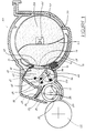
- Figure 1 is a schematic sectional view of a development unit, showing its general features.
- Figure 2 is a schematic representation of the working position of the flexible blade which regulates the height of the toner layer forming the magnetic brush.
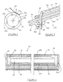
- Figure 3 shows a device to avoid the formation of lumps in the one-component toner inside the development chamber.
- Figure 4 shows a view of the concave side of the removable toner container element.
- Figure 5 shows an end sectional view of the development unit with the removable toner container in place, but not in the working position.
- Figure 6 shows a side sectional view of the removable one-component toner container.
- Figure 7 shows the connection system and clutch that transmits the drive motion to the rotating strip that feeds the one-component toner.
- the magnetic brush development unit 10 comprises a development roller 11 arranged close to a photoconducting drum 12 in a direction parallel to the axis of the photoconducting drum.
- the development roller 11 consists of a sleeve 20 of non-magnetic material that rotates on a structure 30 of the development unit, and inside which are contained a number of stationary permanent magnets 25.
- the magnetic poles of the permanent magnets 25 arranged inside the sleeve 20 are located in such a way that adjacent poles are of opposite magnetic polarity.
- the magnetic brush is brought in contact with the photoconducting drum 12, on which a latent electrostatic image has previously been formed.
- Toner is deposited on the electrostatic image on the drum such that it is developed into a visible image.
- the thickness of the one-component toner layer on the surface 24, and consequently the height of the magnetic brush at the development position 21, is determined mainly by the action of a metering blade 22 fixed at one end to a rigid support 23 of the structure 30.
- the blade 22 rests elastically against the surface 24 of the sleeve 20 along a tangent indicated as "P" in Figure 2 , and consists of a non-magnetic steel strip of thickness from 0.01 to 0.5 mm (preferably from 0.01 to 0.1 mm) coated with a layer of silicone rubber of thickness from 0.1 to 1.0 mm.
- the outside surface 24 of the sleeve 20 is treated by a sand-blasting process, first with alumina particles of an irregular shape with sharp points, and then with glass beads, to impart a surface roughness between 1 and 4 Rz as described, for example, in European Patent Application EP-A- 407125.
- the pressure exerted due to the elastic deformation of the metering blade 22 on the outside surface 24 of the sleeve 20 is adjusted by trial and error as a function of the characteristics of the one-component toner 28, the intensity of the magnetic field, the geometric position of the poles of the permanent magnets 25, and the rotation velocity of the development roller 11, such that the height of the toner layer forming the magnetic brush at the development position 21 will be such as to obtain optimum development of the latent image on the photoconducting drum 12.
- a further element that contributes to determining the height of the magnetic brush toner layer at the development position 21 is the length "d" of a part 22a of the metering blade 22 that projects beyond the point "P" of contact between the blade 22 and the development roller 11 on the side opposite to the support 23.
- the development unit 10 comprises a development chamber 40 defined by a portion lla of the development roller 11, a wall section 26 of the structure 30, and by the elements 27, 32 and 38 which will be more fully described below.
- a sensor device to sense the presence of toner consisting of a rigid metallic non-magnetic wire 41 fixed at either end to opposite walls of the chamber 40.
- the wire 41 is arranged parallel to the sleeve 20 along its entire length, and is connected to an electronic measuring circuit, not shown in the figure, outside the development unit 10; the wire 41 of the toner presence sensor and the sleeve 20 represent the two armatures of a condenser whose capacitance changes depending on whether air or toner 28 is between them, because of their different dielectric constants; this difference in capacity is detected by the electronic measurement circuit, such that a "toner finished" signal is emitted, for example by the illumination of a signal light, to the operator of the electro-photographic apparatus.
- the position of the wire 41 with respect to the sleeve 20 and the sensitivity of the electronic measuring circuit are adjusted so that the "toner finished" signal appears when approximately 50 g of toner 28 remain in the development chamber 40, this quantity being quite sufficient to allow completion of a photocopying job that may be in progress when the signal appears.
- the toner 28 flows into the development chamber 40 through a rectangular slit 37 formed in a movable element 27, which will be more fully described below, and flows out of the development chamber 40 under the action of the magnetic development roller 11; the quantity of toner 28 present in the development chamber 40 is thus variable as a function of the toner consumption, which in turn depends on the quantity of toner required to develop the latent image on the photoconducting drum 12, and on the influx of toner 29 coming from a removable container 43 and pushed by a feed strip 42 through the slit 37 in the movable element 27.
- a stirring device 400 (of which, for simplicity, Figure 3 shows only one end, while the opposite end is identical but a mirror image of that shown) comprising a first stirrer element 44 consisting of a bar 44a of non-magnetic material arranged parallel to the sleeve 20 and of essentially the same length.
- the end part of the stirrer element 44 is bent into the shape of a crank 13 in "swans neck” form, with two sections 16a and 16b of unequal length such that the section 16b is longer than 16a.
- the linear portion 14 of the "swans neck” at one end of the bar 44a and the corresponding linear portion at the opposite end act as revolving pivots on opposite walls of the development chamber 40 between which the said stirrer 44 is caused to rotate so that the lower part of the development chamber 40 is “swept” by the bar 44a, which thereby impedes the formation of lumps and ensures a regular feed of toner to the development roller 11.
- the stirring device 400 also comprises a second stirrer element 45 consisting of a first bar 45a of non-magnetic material, and a third stirrer element 15 also formed of a second bar 15a of non-magnetic material.
- the bars 15a and 45a cooperate with a front fork 46, and with the analogous back fork not shown in Figure 3 , which support and impart movement to both of the bars 45a and 15a; the fork 46 fits over a linear section 13a of the crank 13 and can move transversely with respect to the wire 41 of the toner presence sensor; when the stirrer element 44 is rotated, the bars 45a and 15a each move along a closed path so that the toner at the top and in the middle of the development chamber 40 is mixed continually, thus ensuring the maintenance of correct toner fluidity and preventing the formation of lumps.
- the bar 15a contributes to the avoidance of toner retention between the sleeve 20 and the wire 41 of the toner presence sensor resulting from compaction effect caused by the action of the metering blade 22 on the toner transported by the sleeve 20, even when the total quantity of toner 28 present within the development chamber 40 has fallen below a value of approximately 50 g. This toner retention would impede the correct function of the toner presence sensor.
- the flexible feed strip 42 (see Figure 1 ) in container 43 rotates clockwise, allowing the toner 29 to emerge progressively through a slit 47 formed in the wall of the removable container 43 until the container 43 is completely emptied.
- the elastic properties of the material forming the flexible feed strip 42, its shape, and the position and width of the slit 47 are determined by trial and error as a function of the characteristics of the toner 29, such that a balance is established within the development chamber 40 so that the toner 29 present in the removable container 43 is only fed in when the compaction of the toner 28 in the development chamber 40 remains between values that guarantee correct toner fluidity and avoid the formation of lumps.
- the flexible feed strip 42 was made of polyethyleneterephthalate (PET) approximately 0.1-0.5 (preferably 0.2) mm thick, subdivided into several sections, for example, six sections of equal width, by cuts perpendicular to the rotation axis; the feed slit 47 was approximately 10 mm wide and approximately 320 mm long, and was positioned approximately horizontally; the one-component toner 29 was that already described, with an apparent density of 0.5 to 0.6 g/cm 3 .
- PET polyethyleneterephthalate
- the stirrer elements 44, 15 and 45 contribute to the maintenance in equilibrium of toner 28 contained in the development chamber 40, by causing excess toner to flow towards the slit 47 of the removable container 43, such that under normal working conditions the development chamber 40 contains approximately 80 g of toner 28, compared with a capacity of approximately 90 g calculated on the basis of an apparent density of 0.55 g/cm 3 of toner 28.
- the movable element 27 (see Figure 4 ) consists of a non-magnetic strip 57 in the shape of a semicircular arc in which is formed in an asymmetric position a longitudinal opening which constitutes the slit 37, whose longitudinal edges 27a and 27b are folded back towards the inside and support two sealing elements 35 and 36, consisting of PET strips essentially the same length as the slit 37; along the edge 27b is stuck a further sealing element 74 which consists of a first layer of polyurethane rubber foam over which there is a second layer of felt, while along the two transverse edges 27c and 27d of the longitudinal slit 37 are stuck two sealing elements 33 and 34 constructed in the same way.
- the moving element 27 When the removable container 43 is not present, or is only inserted inside the development unit 10, the moving element 27 is positioned as shown in Figure 5 and the toner 28 present in the development chamber 40 cannot flow back into the area within the development unit 10 that houses the removable container 43, since it is held back by a first sealing element 32 consisting of a flexible PET strip 17 attached at one end to a section of the inside wall 58 of the structure 30, while the other end, to which polyurethane rubber foam 18 is stuck, is held pressed against the side of the movable element 27 by the elasticity of the same flexible PET strip 17; by a second sealing element 31 consisting of polyurethane rubber foam fixed to a section of the inside wall 59 of the structure 30, by a third sealing element 38 consisting of a flexible PET strip stuck to a section of the inside wall 19 of the structure 30; and finally by the continuous wall 27a of the moving element 27 itself.
- a first sealing element 32 consisting of a flexible PET strip 17 attached at one end to a section of the inside wall 58 of
- the removable container 43 (see Figure 6 ) consists of a cylindrical resin tube 49 approximately 320 mm long, closed at both ends by front and back circular flanges 52 and 51, so enclosing a volume that can contain approximately 400 g of one-component toner 29.
- the rectangular feed slot 47 (see Figure 5 ) is formed longitudinally in the wall of the cylindrical tube 49; to allow the transport and storage of the removable container 43, it is normally sealed, for example by a self-adhesive strip not shown in the figure, which is removed after insertion of the removable container 43 into the development unit.
- a handle 50 To the front circular flange 52 (see Figure 6 ) is fixed a handle 50, above which there is an eccentrically positioned element 73 that can be acted on by the thumb of the same hand operating the handle, and whose use will be described below.
- the removable container 43 is inserted into the development unit 10 with the slit 47 in correspondence with the slit 37 of the moving element 27, such that the sealing elements 35 and 36 are pressed against the outside wall of the removable container 43 close to the slit 47 by the elastic reaction caused by the deformation of those sealing elements 35 and 36.
- the removable container 43 To bring the removable container 43 into its working position, as shown in Figure 1 , it must be rotated through approximately 90° anticlockwise; when this is done by simple means, for example a pair of projections attached to the back flange 51, the removable container 43 draws the moving element 27 with it, which thus also rotates through about 90° anticlockwise, moving from the position shown in Figure 5 to that shown in Figure 1 ; after rotation, the slits 47 and 37, which are now aligned, allow the passage of the toner 29 in the removable container 43 into the development chamber 40.
- the element 73 (see Figure 6 ) attached to the handle 50 of the removable container 43 is positioned against a stop, not shown in the figure, attached to the structure 30 in a suitable position to prevent the clockwise rotation of the removable container 43 during the normal operation of the development unit 10; the element 73 can be freed from the stop by being pressed downwards, so allowing the removable container 43 to rotate by about 90° anticlockwise, to enable it to be extracted from the development unit 10 after emptying.
- the container 43 also has an internal shaft 48 that supports the flexible feed strip 42 of the toner 29, and that ends at the front in a pivot 54 which fits into a suitable seating formed in the middle of the front circular flange 52 and within which it can rotate; the back end of the internal shaft 48 passes through a hole formed in the middle of the back circular flange 51 and ends in the shape of a cylindrical cup 55 open towards the outside and free to rotate inside the back circular flange 51; a collar 53 of polyurethane rubber foam prevents the toner 29 in the removable container 43 from escaping through the hole formed in the middle of the back circular flange 51.
- At the bottom of the cylindrical cup 55 there are two projections 56a and 56b pointing outwards, and approximately 2.5 mm high, arranged diametrically opposite one another and of triangular section with the apex outwards.
- the cylindrical cup 55 When the removable container 43 is inserted into the development unit 10, the cylindrical cup 55 is positioned opposite an elastic joint 60 (see Figure 7 ), whose function is to transmit movement to the internal shaft 48 and hence to the flexible feed strip 42 for the one-component toner 29.
- the elastic joint 60 consists of an internal member 61, an external member 62 free to rotate coaxially with the internal member 61, and a helical spring 63 whose ends are attached respectively to the internal member 61 and to the external member 62.
- the internal member 61 comprises a shaft 66 constituting the pivot on which the external member 62 rotates, and a disc 64 on whose face 65 there are two projections 67a and 67b of triangular section arranged diametrically opposite one another and with their apexes turned towards the back circular flange 51 of the removable container 43, while on the face 69 opposite to the face 65 there are two projections 68 also diametrically opposite one another.
- the external member 62 comprises a toothed wheel 70 and hub 72 on which there are two projections 71 diametrically opposite one another and on a diameter equal to that on which the projections 68 of the internal member 61 are arranged.
- the pairs of projections 68 and 71 under the action of the helical spring 63, hold the internal member 61 and the outside member 62 motionless with respect to one another in the event of clockwise rotation, while in the case of anticlockwise rotation they allow the internal member 61 to rotate by about 90° with respect to the outside member 62 before coming up against each other, having as the opposing couple only the torsional couple of the helical spring 63.
- the elastic joint 60 allows the operator to rotate the removable container 43, after its insertion into the development unit 10, by about 90° anticlockwise to position both the moving element 27 and the removable container 43 in the working position, as shown in Figure 1 , by exerting a couple of moderate strength.
- the removable container 43 can rotate anticlockwise by about 90° without at the same time turning the internal shaft 48 and the flexible feed strip 42 for the one-component toner 29, an operation that could require a high couple due to the compaction effect of the toner 29 caused by the transport and storage conditions of the removable container 43 itself.
- the toothed wheel 70 is moved by a dynamometric clutch 75 comprising a driving toothed wheel 77 and a driven toothed wheel 76 rotating on a pivot 78; the facing surfaces of the driven toothed wheel 76 and the driving toothed wheel 77 both have identical frontal grooves, not shown in the figure, forming teeth of trapezoidal shape, and are held in contact with one another by the axial pressure exerted by a compression spring 79.
- the toothed driving and driven wheels 77 and 76 remain in fixed positions with respect to one another thanks to the engagement of their frontal teeth, while when the opposing couple of the toothed wheel 70 exceeds the value of 5-15 (preferably 7-10) kg.cm, the axial pressure exerted by the reciprocal movement of the trapezoidal teeth on the opposing front surfaces of the driven toothed wheel 76 and the driving toothed wheel 77 overcomes the axial pressure of the compression spring 79, and the toothed wheels 76 and 77 move apart from one another such that the toothed drive wheel 77 can rotate without transmitting motion to the toothed driven wheel 76 and consequently to the toothed wheel 70, so safeguarding the integrity of all the elements that cooperate in the transmission of motion to the feed strip 42.
Landscapes
- Physics & Mathematics (AREA)
- General Physics & Mathematics (AREA)
- Dry Development In Electrophotography (AREA)
Description
Claims (15)
- Development unit (10) for photocopiers, comprising means to receive a removable container (43) containing a magnetizable one-component toner (29), means (42) for the selective transfer of the toner from the removable container into a development chamber (40) of the unit, means for stirring (15,44,45) arranged inside the development chamber, and a development roller (11) comprising a rotating non-magnetic sleeve (20) to which a layer of the toner adheres to form a magnetic brush,
characterized in that:the means for the transfer of the toner consists of at least one flexible strip (42) made of a non-magnetic material fixed to a rotating shaft (48) inside the container (43) and extending perpendicularly to the rotating shaft in at least one direction until it comes in contact with an internal wall of the container;the means for stirring consist of a number of bars (15,44,45) made of a non-magnetic material extending parallel to the rotating development roller (11) so as to describe closed paths in different zones of the development chamber (40), and cooperating with the flexible strip (42) to regulate the transfer of the toner and to avoid the formation of lumps. - Development unit according to Claim 1, characterized in that the means for stirring comprise:a first bar (44) of non-magnetic material extending parallel to the development roller and having its two ends bent in the form of a crank (13,14,44a) rotating on opposite walls of the development chamber, such that the first bar describes a cylindrical path parallel and adjacent to the development roller;a pair of fork shaped elements (46) supported by the crank and oscillating inside the development chamber, each of which has two arms extending into the upper part of the development chamber, each of the two arms supporting respectively a second and a third bar (15,45) of non-magnetic material, the fork shaped element being moved by the crank such that the second and third bars describe two cylindrical paths parallel to the development roller at the top and at the middle of the development chamber (40).
- Development unit according to Claim 1 or 2, also comprising sensing means to detect and signal emptying of the removable container of toner, characterized in that the sensing means consist of a non-magnetic wire 41 arranged parallel to the surface of the development roller (11) and located inside the development chamber (40) at such a height that the wire is substantially immersed in the toner throughout the time that the means for transfer are transferring the toner from the removable container (43) to the development chamber (40), but above the level of the toner once all of the toner contained in the removable container has been transferred into the development chamber.
- Development unit according to Claim 3, characterized in that the non-magnetic metallic wire (41) guides the movement of the fork shaped elements (46), such that the arms of the fork shaped elements can move outside and perpendicularly to the axis of the wire.
- Development unit according to Claim 1, characterized in that the flexible strip (42) consists of a polyethyleneterephthalate (PET) strip of thickness between 0.1 and 0.5 mm.
- Development unit according to Claim 1 or 5, characterized in that the flexible strip is subdivided into several essentially equal sections by slots perpendicular to the rotating shaft.
- Development unit according to Claim 1, comprising in addition means for containing the toner (29) in the development chamber (40), and in which the removable container (43) can be moved from a working position to an extraction position, characterised in that the containing means comprise a moving element (27), situated between the development chamber and the removable container, consisting of a plate (27) in which is formed an aperture (37) for passage of the toner and sealing gaskets (35,36) fitted around the aperture; the moving element can be moved by two pairs of projections (51) attached to the removable container, in such a way that when the removable container is in the working position, the aperture (37) is aligned with an analogous aperture (47) in the removable container, so allowing transfer of the toner from the removable container; while when the removable container is in the extraction position or has been extracted, the aperture (37) in the moving element (27) is in such a position that the development chamber is no longer in communication with the means for accommodating the removable container.
- Development unit according to Claim 1, characterized in that the rotating non-magnetic sleeve possesses an outer surface (24) treated by a sand-blasting process, first with particles of irregular shape and sharp points, and a second time with particles of essentially rounded shape.
- Development unit according to Claim 1, characterized in that the rotating non-magnetic sleeve encloses a number of stationary permanent magnets (25) such as to generate four magnetic poles of alternating polarity, the first of which, corresponding to a development position of the latent image, has a magnetic induction of between 800 and 1200 G, the second has a magnetic induction of 600-900 G, and is displaced with respect to the first pole by 60-100° in the rotation direction of the non-magnetic cylinder, the third has a magnetic induction of 600-900 G and is further displaced with respect to the second pole by 60-100°, and the fourth has a magnetic induction of 500-900 G and is still further displaced with respect to the third pole by 80-120°.
- Development unit according to Claim 1, also comprising means (22) for regulating the thickness of the magnetic brush, characterized in that the means consist of a flexible non-magnetic blade (22) fixed at one end to the development unit (10), and arranged tangentially with respect to the development roller such that, it projects beyond to a contact point "P" with the roller, by a length between 1 and 10 mm, so as to intercept the toner forming the magnetic brush and moving in the rotation direction of the development sleeve (20).
- Development unit according to Claim 10, characterized in that the non-magnetic flexible blade consists of a non-magnetic steel strip of thickness from 0.01 to 0.5 mm coated with silicone rubber of thickness from 0.1 to 1.0 mm.
- Development unit according to Claim 10, characterized in that the flexible non-magnetic blade is pressed elastically against the surface of the development roller with a predetermined pressure between 0.1 and 2.0 N/cm.
- Development unit according to Claim 1, comprising means for transmitting the movement of a motor to the flexible strip (42), characterized in that the transmitting means consist of an elastic joint (60) and of a dynamometric clutch (25), where the elastic joint is attached to the rotating shaft (48) within the removable container (43) to which is fixed the flexible strip, and the dynamometric clutch is located between the elastic joint and the motor.
- Development unit according to Claim 13, characterized in that the elastic joint applies to the rotating shaft a couple of magnitude less than the magnitude of the opposing couple of the flexible strip, whereby the removable container (43) can be rotated by approximately 90° together with the strip and the toner irrespective of the orientation with which the removable container has been inserted in the development unit.
- Development unit according to Claim 14, characterised in that the dynamometric clutch (75) imparts movement to the elastic joint only when the resistance couple is less than a predetermined value between 5 and 15 kg.cm.
Applications Claiming Priority (2)
| Application Number | Priority Date | Filing Date | Title |
|---|---|---|---|
| IT94TO000066A IT1268013B1 (en) | 1994-02-07 | 1994-02-07 | DEVELOPMENT UNIT FOR ELECTROPHOTOCOPIERS |
| ITTO940066 | 1994-02-07 |
Publications (2)
| Publication Number | Publication Date |
|---|---|
| EP0666516A1 EP0666516A1 (en) | 1995-08-09 |
| EP0666516B1 true EP0666516B1 (en) | 1998-09-16 |
Family
ID=11412112
Family Applications (1)
| Application Number | Title | Priority Date | Filing Date |
|---|---|---|---|
| EP95300642A Expired - Lifetime EP0666516B1 (en) | 1994-02-07 | 1995-02-01 | Development unit for electrophotographic copier |
Country Status (4)
| Country | Link |
|---|---|
| US (1) | US5581334A (en) |
| EP (1) | EP0666516B1 (en) |
| DE (1) | DE69504720T2 (en) |
| IT (1) | IT1268013B1 (en) |
Families Citing this family (20)
| Publication number | Priority date | Publication date | Assignee | Title |
|---|---|---|---|---|
| US5678147A (en) * | 1995-12-28 | 1997-10-14 | Brother Kogyo Kabushiki Kaisha | Toner containing device having integrally molded shaft and blade assembly and method for feeding toner into a development case of a development device |
| US5907756A (en) * | 1996-08-07 | 1999-05-25 | Minolta Co., Ltd. | Toner replenishment device and toner bottle |
| US5875378A (en) * | 1996-12-20 | 1999-02-23 | Lexmark International, Inc. | Toner cartridge with hopper exit agitator |
| US5890034A (en) * | 1997-02-28 | 1999-03-30 | Brother Kogyo Kabushiki Kaisha | Developing device for image forming apparatus and toner cartridge for use in the developing device |
| JP2000293024A (en) * | 1999-04-06 | 2000-10-20 | Matsushita Graphic Communication Systems Inc | Toner cartridge and recording device using toner cartridge |
| CN1900837B (en) | 2000-02-17 | 2012-10-03 | 株式会社理光 | Toner storing device, toner replenishing method and device |
| JP3958511B2 (en) | 2000-09-28 | 2007-08-15 | 株式会社リコー | Toner supply device and image forming apparatus |
| EP1626315A3 (en) | 2001-01-31 | 2006-08-02 | Ricoh Company, Ltd. | Toner container and image forming apparatus using the same |
| KR100492122B1 (en) * | 2003-07-02 | 2005-06-01 | 삼성전자주식회사 | Developing unit for image forming apparatus |
| JP4208905B2 (en) * | 2006-07-11 | 2009-01-14 | シャープ株式会社 | Image forming apparatus |
| JP2009192958A (en) * | 2008-02-15 | 2009-08-27 | Sharp Corp | Toner bottle and image forming apparatus |
| JP4893809B2 (en) | 2009-11-30 | 2012-03-07 | ブラザー工業株式会社 | Development unit |
| JP2018013606A (en) * | 2016-07-21 | 2018-01-25 | 富士ゼロックス株式会社 | Developing device and image forming apparatus |
| JP6938874B2 (en) * | 2016-09-09 | 2021-09-22 | 富士フイルムビジネスイノベーション株式会社 | Develop equipment and image forming equipment |
| JP6816533B2 (en) * | 2017-01-27 | 2021-01-20 | コニカミノルタ株式会社 | Image forming device |
| JP2019184843A (en) * | 2018-04-11 | 2019-10-24 | キヤノン株式会社 | Development device, image formation device and cartridge |
| JP7131097B2 (en) * | 2018-06-06 | 2022-09-06 | 京セラドキュメントソリューションズ株式会社 | developer stirring member, developer supply unit, image forming apparatus |
| JP7131096B2 (en) * | 2018-06-06 | 2022-09-06 | 京セラドキュメントソリューションズ株式会社 | developer stirring member, developer supply unit, image forming apparatus |
| JP7484657B2 (en) * | 2020-10-23 | 2024-05-16 | セイコーエプソン株式会社 | Powder Supply Device |
| JP7613069B2 (en) * | 2020-11-27 | 2025-01-15 | セイコーエプソン株式会社 | Powder Supply Device |
Citations (2)
| Publication number | Priority date | Publication date | Assignee | Title |
|---|---|---|---|---|
| EP0496602A1 (en) * | 1991-01-22 | 1992-07-29 | Compaq Computer Corporation | Electrophotographic printing system |
| EP0518682A2 (en) * | 1991-06-14 | 1992-12-16 | Oki Electric Industry Co., Ltd. | Developing device |
Family Cites Families (14)
| Publication number | Priority date | Publication date | Assignee | Title |
|---|---|---|---|---|
| US4468111A (en) * | 1981-05-20 | 1984-08-28 | Mita Industrial Company Limited | Developing device for use on an electrostatic copying apparatus |
| US4456364A (en) * | 1982-06-09 | 1984-06-26 | Pitney Bowes Inc. | Magnetic brush hopper agitator for electrophotocopier |
| JPS6141162A (en) * | 1984-07-31 | 1986-02-27 | Ricoh Co Ltd | Toner replenishment device for dry development device |
| JPS61138968A (en) * | 1984-12-12 | 1986-06-26 | Oki Electric Ind Co Ltd | Dry development device |
| JPS61158356A (en) * | 1984-12-29 | 1986-07-18 | Ricoh Co Ltd | Toner feeder |
| US4743936A (en) * | 1987-08-14 | 1988-05-10 | Xerox Corporation | Transport having compensation for material packing |
| US4993829A (en) * | 1988-10-24 | 1991-02-19 | Konica Corporation | Developing apparatus for an image forming apparatus |
| US5134441A (en) * | 1989-05-30 | 1992-07-28 | Canon Kabushiki Kaisha | Developing device and process cartridge including the device |
| EP0437864B1 (en) * | 1990-01-17 | 1994-03-30 | Agfa-Gevaert N.V. | Electrostatic latent image developing device |
| JPH07113794B2 (en) * | 1990-03-19 | 1995-12-06 | 富士ゼロックス株式会社 | Development device |
| JPH04260075A (en) * | 1991-02-15 | 1992-09-16 | Ricoh Co Ltd | Developing device |
| US5541714A (en) * | 1992-05-18 | 1996-07-30 | Fujitsu Limited | Developer cartridge and image forming apparatus using the same |
| JPH0683188A (en) * | 1992-08-31 | 1994-03-25 | Brother Ind Ltd | Developing device for electrophotographic device |
| US5430530A (en) * | 1993-10-04 | 1995-07-04 | Xerox Corporation | Admix Housing |
-
1994
- 1994-02-07 IT IT94TO000066A patent/IT1268013B1/en active IP Right Grant
-
1995
- 1995-01-19 US US08/375,484 patent/US5581334A/en not_active Expired - Lifetime
- 1995-02-01 DE DE69504720T patent/DE69504720T2/en not_active Expired - Fee Related
- 1995-02-01 EP EP95300642A patent/EP0666516B1/en not_active Expired - Lifetime
Patent Citations (2)
| Publication number | Priority date | Publication date | Assignee | Title |
|---|---|---|---|---|
| EP0496602A1 (en) * | 1991-01-22 | 1992-07-29 | Compaq Computer Corporation | Electrophotographic printing system |
| EP0518682A2 (en) * | 1991-06-14 | 1992-12-16 | Oki Electric Industry Co., Ltd. | Developing device |
Also Published As
| Publication number | Publication date |
|---|---|
| DE69504720T2 (en) | 1999-03-11 |
| ITTO940066A1 (en) | 1995-08-07 |
| DE69504720D1 (en) | 1998-10-22 |
| IT1268013B1 (en) | 1997-02-20 |
| EP0666516A1 (en) | 1995-08-09 |
| US5581334A (en) | 1996-12-03 |
| ITTO940066A0 (en) | 1994-02-07 |
Similar Documents
| Publication | Publication Date | Title |
|---|---|---|
| US5581334A (en) | Electrostatic image developing device having toner flow control and lumps formation prevention ability | |
| US5987298A (en) | Image forming apparatus including a toner recycling mechanism | |
| US4739907A (en) | Developer storage and dispenser apparatus | |
| US4506804A (en) | Volume detecting device | |
| US9104134B2 (en) | Toner level sensing for replaceable unit of an image forming device | |
| US9128443B2 (en) | Toner level sensing for replaceable unit of an image forming device | |
| JP3417240B2 (en) | Electrophotographic equipment | |
| US10289024B2 (en) | Toner level sensing for a replaceable unit of an image forming device | |
| US4668074A (en) | Device for detecting the remaining amount of developer | |
| EP0249152B1 (en) | Developing unit for an electrophotographic apparatus | |
| JP4261993B2 (en) | Developer transport device and image forming apparatus | |
| JPH10177300A (en) | Electrophotographic apparatus and developer discharging method | |
| JPH08202138A (en) | Image forming device | |
| JP2599994B2 (en) | Developer detection device | |
| US5426486A (en) | Toner monitor having magnetic field control | |
| JPH0619302A (en) | Developing device for electrophotographic device | |
| JPS63118173A (en) | Developing device | |
| JPH08248748A (en) | Developing device | |
| JPH0452774Y2 (en) | ||
| JP2004287355A (en) | Image forming device | |
| JPH07333971A (en) | Developing device for electrophotographic device | |
| JPH0126059B2 (en) | ||
| JPS6240479A (en) | developing device | |
| JP2001117361A (en) | Developing device and image forming device | |
| JP2000075625A (en) | Developer amount detecting device, developing device, and image forming apparatus including the same |
Legal Events
| Date | Code | Title | Description |
|---|---|---|---|
| PUAI | Public reference made under article 153(3) epc to a published international application that has entered the european phase |
Free format text: ORIGINAL CODE: 0009012 |
|
| AK | Designated contracting states |
Kind code of ref document: A1 Designated state(s): DE FR GB NL |
|
| 17P | Request for examination filed |
Effective date: 19951212 |
|
| 17Q | First examination report despatched |
Effective date: 19970829 |
|
| GRAG | Despatch of communication of intention to grant |
Free format text: ORIGINAL CODE: EPIDOS AGRA |
|
| GRAG | Despatch of communication of intention to grant |
Free format text: ORIGINAL CODE: EPIDOS AGRA |
|
| GRAH | Despatch of communication of intention to grant a patent |
Free format text: ORIGINAL CODE: EPIDOS IGRA |
|
| GRAH | Despatch of communication of intention to grant a patent |
Free format text: ORIGINAL CODE: EPIDOS IGRA |
|
| GRAA | (expected) grant |
Free format text: ORIGINAL CODE: 0009210 |
|
| AK | Designated contracting states |
Kind code of ref document: B1 Designated state(s): DE FR GB NL |
|
| REF | Corresponds to: |
Ref document number: 69504720 Country of ref document: DE Date of ref document: 19981022 |
|
| ET | Fr: translation filed | ||
| PLBE | No opposition filed within time limit |
Free format text: ORIGINAL CODE: 0009261 |
|
| STAA | Information on the status of an ep patent application or granted ep patent |
Free format text: STATUS: NO OPPOSITION FILED WITHIN TIME LIMIT |
|
| 26N | No opposition filed | ||
| REG | Reference to a national code |
Ref country code: GB Ref legal event code: IF02 |
|
| PGFP | Annual fee paid to national office [announced via postgrant information from national office to epo] |
Ref country code: NL Payment date: 20080203 Year of fee payment: 14 Ref country code: GB Payment date: 20080130 Year of fee payment: 14 Ref country code: DE Payment date: 20080124 Year of fee payment: 14 |
|
| PGFP | Annual fee paid to national office [announced via postgrant information from national office to epo] |
Ref country code: FR Payment date: 20080208 Year of fee payment: 14 |
|
| GBPC | Gb: european patent ceased through non-payment of renewal fee |
Effective date: 20090201 |
|
| NLV4 | Nl: lapsed or anulled due to non-payment of the annual fee |
Effective date: 20090901 |
|
| REG | Reference to a national code |
Ref country code: FR Ref legal event code: ST Effective date: 20091030 |
|
| PG25 | Lapsed in a contracting state [announced via postgrant information from national office to epo] |
Ref country code: NL Free format text: LAPSE BECAUSE OF NON-PAYMENT OF DUE FEES Effective date: 20090901 |
|
| PG25 | Lapsed in a contracting state [announced via postgrant information from national office to epo] |
Ref country code: DE Free format text: LAPSE BECAUSE OF NON-PAYMENT OF DUE FEES Effective date: 20090901 |
|
| PG25 | Lapsed in a contracting state [announced via postgrant information from national office to epo] |
Ref country code: GB Free format text: LAPSE BECAUSE OF NON-PAYMENT OF DUE FEES Effective date: 20090201 Ref country code: FR Free format text: LAPSE BECAUSE OF NON-PAYMENT OF DUE FEES Effective date: 20090302 |