BACKGROUND OF THE INVENTION
1. Field of the Invention
The present invention relates to an apparatus for driving
a piston by fluid pressure such as pneumatic pressure or
hydraulic pressure.
2. Description of Prior Art
Conventionally, as an apparatus for driving a piston by
fluid pressure which is a subject for the present invention
there has been known the one disclosed in U.S. Pat. No.
5,050,482. This is the apparatus previously proposed by the
assignee of the present invention and its basic constitution
is as follows.
As illustrated in a system view of Fig. 5, a piston 8 is
vertically movably inserted into a cylinder 7. A driving
chamber 9 is arranged between an upper wall 7a of the cylinder
7 and the piston 8. Pressure fluid is supplied to and
discharged from the driving chamber 9 by a supply-discharge
valve 13. The supply-discharge valve 13 is adapted to be
switched between a supply position X of the pressure fluid and
a discharge position Y thereof by a pilot valve 18. The
symbol 14 designates a pressure supply port of the pressure
fluid and the symbol 15 does a pressure discharge port
thereof.
The basic constitution will be explained in detail with
reference to Fig. 6 illustrating the apparatus disclosed in
the above-mentioned prior art publication hereinafter.
The supply-discharge valve 13 comprises a cylindrical
supply-discharge valve casing 29 disposed above the cylinder 7
and a supply-discharge valve member 30 vertically movably
inserted into the supply-discharge valve casing 29. A supply
actuation chamber 33 communicated with the pressure supply
port 14 is arranged below the supply-discharge valve member 30
and a discharge actuation chamber 35 to be selectively
communicated with the pressure supply port 14 and a pressure
relief port 55 is arranged above the supply-discharge valve
member 30.
The pilot valve 18 comprises a sleeve 44 inserted into a
bore 30d of the supply-discharge valve member 30, a spool
valve member 46 vertically movably inserted into the sleeve
44. an annular sealing member 48 arranged between the pressure
supply port 14 and the discharge actuation chamber 35 and a
pressure relief valve member 57 arranged between the discharge
actuation chamber 35 and the pressure relief port 55. The
annular sealing member 48 is fitted between an outer
peripheral surface of the spool valve member 46 and a lower
portion of the bore 30d so as to be brought into contact with
a lower portion of the sleeve 44 from below. Further, the
lower portion of the spool valve member 46 is fixedly secured
to the piston 8.
As shown in Figs. 5 and 6, the apparatus 2 for driving the
piston by the fluid pressure having the basic constitution
operates as follows.
When a pressure fluid supply valve 16 is opened, a
pressure fluid such as a pressure air or a pressure oil is
supplied from a fluid pressure source 17 to operate the
driving apparatus 2. When the valve 16 is closed, the pressure
fluid supply is stopped and then the operation of the driving
apparatus 2 is stopped.
As shown in the left half view of Fig. 6, while the
operation is stopped, the piston 8 and the spool valve member
46 are pushed back to the top dead center by a return spring
11, so that the supply-discharge valve member 30 is pushed up
to the supply position X.
While the operation is continued, a descending drive
stroke illustrated in the left half view thereof and an
ascending return stroke illustrated in the right half view
thereof are repeated.
During the descending drive stroke, since the pressure
relief valve member 57 is opened and the pressure fluid within
the discharge actuation chamber 35 is released from the
pressure relief port 55 to the pressure discharge port 15, the
supply-discharge valve member 30 is pushed up by the fluid
pressure of the supply actuation chamber 33 to the supply
position X on the upper side and the pressure fluid always
supplied to the supply actuation chamber 33 is forced into a
driving chamber 9 from a working chamber 32 to descend the
piston 8.
During the ascending return stroke, when the piston 8 is
near the bottom dead center, as shown in the right half view
thereof, the annular sealing member 48 is opened and the
pressure fluid always supplied from the pressure supply port
14 is introduced into the discharge actuation chamber 35
through the sleeve 44, so that the supply-discharge valve
member 30 is pushed down by the fluid pressure to the
discharge position Y on the lower side and the pressure fluid
within the driving chamber 9 is released from the working
chamber 32 to the pressure discharge port 15 through a
discharge chamber 34 to ascend and return the piston 8 by the
return spring 11. Thus, when the piston 8 reaches the top
dead center, as shown in the left half view thereof, the
pressure relief valve member 57 is opened, switching over to
the descending drive stroke.
In the basic constitution, conventionally the pilot valve
18 is further constituted as follows.
As shown in Fig. 6, a cylinder bore 91 to be communicated
with the discharge actuation chamber 35 is formed vertically
in an upper portion of the supply-discharge valve casing 29, a
piston 92 formed in an upper portion of the sleeve 44 is
airtightly inserted into the cylinder bore 91 through an 0-ring
93, a pressure receiving chamber 94 is formed below the
piston 92, and a return spring 95 for urging the sleeve 44
downward is provided.
As noted above, the prior art has such an advantage that
the driving apparatus 2 can be prevented from stopping at an
extremely low speed.
That is, as shown in Fig. 5, while a hydraulic pump 3 of
the plunger type is driven by the driving apparatus 2 to
continue the pressure fluid supply even after completion of an
extension of a hydraulic cylinder 86, when an extremely small
amount of pressure oil leaks from a hydraulic actuation
chamber 87, a switching valve 88 or the like or an extremely
small amount of pressure oil enters a seal clearance of a
sealing member, the piston 8 drives a plunger 22 of the
hydraulic pump 3 at an extremely slow speed to supplement that
extremely small amount of pressure oil.
When the piston 8 is driven at the extremely slow speed in
this way to access the bottom dead center and the spool valve
member 46 passes by the annular sealing member 48 at the
extremely slow speed to separate therefrom a small distance,
the pressure fluid within the pressure supply port 14 flows
into the discharge actuation chamber 35 to slowly push down
the supply-discharge valve member 30 by a force corresponding
to a pressure imposed onto a discharge pressure receiving
surface 30c. On a midway of that slow pushing down, since the
working chamber 32 is communicated with both the supply
actuation chamber 33 and the discharge chamber 34, the
pressure fluid within the driving chamber 9 is released from
the working chamber 32 to the pressure discharge port 15.
Therefore, provided that a descending speed of the supply-discharge
valve member 30 is extremely slow, the piston 8 is
pushed up by a resilient force of the return spring 11 before
completion of its descending stroke and the spool valve member
46 closes the sealing member 48 again on a midway of opening.
Thereupon, a low pressure fluid is enclosed within the
discharge actuation chamber 35 as well as the pressure fluid
within the supply actuation chamber 33 is discharged from the
working chamber 32 to the discharge chamber 34 along a
shortcircuit. As a result, the supply-discharge valve member
30 stops on a midway of descending due to a balance between a
pushing-down force applied from the discharge actuation
chamber 35 and a pushing-up force applied from the supply
actuation chamber 33, so that it becomes impossible to drive
the piston 8 downward and the driving apparatus 2 is stopped.
But, according to the above-mentioned prior art, when the
spool valve member 46 is descended at the extremely slow speed
and its outer peripheral surface separates from an inner
peripheral surface of the annular sealing member 48 at the
extremely slow speed, the pressure fluid within the pressure
supply port 14 is introduced into the sleeve 44 through a
valve opening clearance between the spool valve member 46 and
the sealing member 48 to gradually increase a pressure within
the pressure receiving chamber 94 at the extremely slow speed.
Thereupon, when the pressure within the pressure receiving
chamber 94 reaches a predetermined pressure, as indicated by a
solid line in the right half view, since the sleeve 44 is
ascended by that internal pressure against two springs 58, 95
so that also the sealing member 48 is pushed up accompanying
therewith, the sealing member 48 is quickly separated from the
spool valve member 46.
Thereupon, the pressure fluid within the pressure supply
port 14 is introduced into the discharge actuation chamber 35
through the large valve opening clearance to quickly increase
the pressure within the discharge actuation chamber 35, to
strongly push down and quickly descend the supply-discharge
valve member 30 by the increased pressure and to switch the
supply-discharge valve member 30 to the discharge position Y
in the right half view. Since the supply-discharge valve
member 30 is strongly pushed down and quickly descended in
that way, its midway stop during descending can be prevented.
As a result, it is possible to prevent the driving apparatus 2
from falling into an abnormal stop.
In this way, the prior art has such an advantage that the
driving apparatus 2 can be prevented from stopping even when
being driven at the extremely slow speed. But, there still
remains a problem to be improved as follows.
That is, since the annular sealing member 48 has its inner
peripheral surface adapted to come into slidable contact with
an outer peripheral surface of the spool valve member 46 and
its outer peripheral surface adapted to come into slidable
contact with the bore 30d, wearing-out is increased as a total
operation time of the driving apparatus 2 becomes longer. so
that the sealing performance degrades.
While the piston 8 is stopped at a midway height by an
increase of pressure within a pump chamber 21 during the
descending drive of the piston 8. when the pressure fluid
within the pressure supply port 14 leaks into the sleeve 44
due to the degradation of the sealing performance of the
sealing member 48, the leaked pressure fluid increases the
pressure within the discharge actuation chamber 35 at the
extremely slow speed, so that the supply-discharge valve
member 30 is descended at the extremely slow speed by that
increased pressure. Therefore, due to the same reason as that
described above, the supply-discharge valve member 30 stops at
a midway descend position, so that the driving apparatus 2
falls into the abnormal stop.
SUMMARY OF THE INVENTION
It is an object of the present invention to reliably
prevent an abnormal stopping of a driving apparatus.
The state of the art indicated by the pre-characterizing part
of the independent claim is represented by the
aforementioned document US-A-5050482.
The invention provides an apparatus for driving a piston by
fluid pressure including a fluid pressure supply-discharge
valve for supplying and discharging a pressure fluid to and
from a driving chamber facing a piston, a supply-discharge
valve member so accommodated within a supply-discharge valve
casing of the supply-discharge value as to be switchably
movable, there being on opposite sides of the
supply-discharge valve member a supply actuation chamber for
switching the supply-discharge valve member to a supply
position and a discharge actuation chamber for switching the
valve member to a discharge position, and a pilot valve for
supplying and discharging the pressure fluid to and from the
discharge actuation chamber, characterised in that between
the discharge actuation chamber and an outside space of the
supply-discharge valve casing there is a valve means
including a closure member disposed to be held in an open
state, which allows fluid flow from the discharge actuation
chamber to the outside space by way of a restriction
passage, while the pressure within the discharge actuation
chamber is lower than a predetermined pressure, and to move
to a closed state, which prevents fluid flow from the
discharge actuation chamber to the outside space, when the
pressure within the discharge actuation chamber exceeds the
predetermined pressure.
The valve means may comprise a valve bore communicating with
the discharge actuation chamber, the closure member being
reciprocable within the valve bore,an inlet chamber formed
between one end wall of the valve.bore and the closure
member, an outlet chamber formed between the other end wall
of the valve bore and the closure member, a valve seat
formed in a wall surface of the outlet chamber and a closing
valve surface formed in the closure member and a resilient
member for separating the valve surface from the valve seat,
the outlet chamber and the inlet chamber being connected
with each other by the restriction passage.
The restriction passage may be constituted by a fitting
clearance between the inner peripheral surface of the valve
bore and an outer peripheral surface of the closure member,
and the valve seat is disposed in the other end wall of the
valve bore.
The pilot valve may comprise a sleeve inserted into a bore
of the supply-discharge valve member, a spool valve member
vertically movably inserted into the sleeve, an annular
sealing member interposed between a pressure supply port and
the discharge actuation chamber, and a pressure relief
valve member interposed between the discharge actuation
chamber and a pressure discharge port, the annular sealing
member being fitted between an outer peripheral surface of
the spool valve member and the bore, a receiving portion
adapted to be brought into contact with the annular sealing
member from above being formed in a lower portion of the
sleeve, and the spool valve member being connected to the
piston.
Preferably the valve bore is formed substantially coaxially
to the bore of the supply-discharge valve member,the sleeve
is inserted vertically movably into the bore, the closure
member is fixedly secured to an upper portion of the sleeve,
and the pressure relief valve member is disposed within an
upper portion of the sleeve.
Preferably a pressure supply passage for communicating the
pressure supply port with the discharge actuation chamber is
formed in an upper portion of the spool valve member, an
upper end of the pressure supply passage is opened in the
upper surface of the spool valve member, and a lower end of
the pressure supply passage is opened in an outer peripheral
surface of the spool valve member, and the annular sealing
member comprises a tubular saddle member externally fitted
around the outer peripheral surface of the spool valve
member and an O-ring externally fitted around an outer
peripheral surface of the tubular saddle member.
The preferred form of the invention can provide the
following advantages.
When the extremely small amount of the pressure fluid is
supplied to the discharge actuation chamber at the time of
commencement of the pressure fluid supply by the pilot valve
or by the leak and the like from the sealing portion of the
pilot valve, the pressure increase of the discharge actuation
chamber can be prevented by discharging the supplied pressure
fluid from the restriction passage as well as the pressure
within the discharge actuation chamber can be increased
quickly by an effect of the restriction passage at the time of
increase of the supply amount of the pressure fluid.
Accordingly, it is possible to strongly push the supply-discharge
valve member from the supply position to the
discharge position and the supply-discharge valve member can
be prevented from stopping during its switching. As a result,
the operation of the driving apparatus can be continued.
By the way, when the restriction passage is arranged
between an inlet chamber of the opening-closing means and an
outlet chamber thereof and the opening-closing valve member is
so constituted as to be moved for valve closing by a
differential pressure between both those chambers, the
opening-closing means becomes simple in constitution and
reliable in operation.
When the restriction passage is constituted by a fitting
clearance between the valve bore and the opening-closing valve
member provided in the opening-closing means, since it becomes
possible to finish surface roughness and the like of the
restriction passage with high accuracy, it becomes easy to set
a flowing resistance of the restriction passage to a desired
value and an operational accuracy of the opening-closing means
enhances.
When the valve bore and the bore of the supply-discharge
valve member are formed coaxially and the opening and closing
valve member is fixedly secured to an upper portion of the
sleeve inserted into the bore, the number of component members
becomes less and the constitution becomes much simpler.
Further, when a pressure supply passage is formed in an
upper portion of the spool valve member and a tubular saddle
member is externally fitted around the outer peripheral
surface of the spool valve member, durability of the annular
sealing member improves greatly.
BRIEF DESCRIPTION OF THE DRAWINGS
Figs. 1 through 4 show one embodiment of the present
invention;
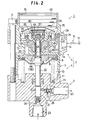
Fig. 1 is an enlarged detailed view of Fig. 2 and a
partial view of a supply-discharge valve of an apparatus for
driving a piston by fluid pressure;
Fig. 2 is a vertical sectional view of a booster pump
apparatus provided in the driving apparatus;
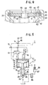
Fig. 3 is a schematic view for explaining an operation of
the driving apparatus;
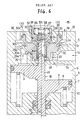
Fig. 4 is a partial view showing a variant example of an
opening-closing means disposed in the supply-discharge valve;
Fig. 5 is a system view showing a basic constitution as a
premise of the present invention; and
Fig. 6 shows a conventional example and is a view
corresponding to Fig. 3.
DETAILED DESCRIPTION OF THE PREFERRED EMBODIMENTS
One embodiment of the present invention will be explained
with reference to the accompanying drawings hereinafter.
Figs. 1 through 3 example a driving apparatus of the present
invention applied to a booster pump apparatus.
Fig. 1 is an enlarged detailed view of Fig. 2. Fig. 2 is
a vertical sectional view of the booster pump apparatus.
Fig. 3 is a view for explaining an operation of the driving
apparatus.
Incidentally, in this embodiment, component members having
the same constitutions as those of the aforementioned
conventional example (refer to Figs. 5 and 6) are, in
principle, designated with the same symbols.
As shown in Fig. 2, the booster pump apparatus 1 comprises
an apparatus 2 for driving a piston by air pressure (fluid
pressure) adapted to generate reciprocating linear movement by
making use of the compressed air and a hydraulic pump 3 of the
plunger type adapted to deliver a high-pressure oil when being
driven by the driving apparatus 2.
The driving apparatus 2 comprises a driving apparatus main
body 4 adapted to convert pressure energy of pressurized air
into power and supply-discharge means 5 for supplying and
discharging the compressed air to and from the driving
apparatus main body 4. These main body 4 and supply-discharge
means 5 are tightly connected to the hydraulic pump
3 by a plurality of tie rods 6 (herein, only one rod is
illustrated).
The driving apparatus main body 4 is of the single-acting
spring-returned type.
That is, the piston 8 is inserted airtightly into the
cylinder 7 so as to be vertically slidable. The driving
chamber 9 is formed between the upper wall 7a of the cylinder
7 and the piston 8, a spring chamber 10 is formed between the
lower wall 7b of the cylinder 7 and the bottom of the piston
8, and a return spring 11 is installed in the spring chamber
10. When the compressed air is supplied to the driving
chamber 9, the piston 8 is driven toward the bottom dead
center against a resilient force of the return spring 11.
When the compressed air is discharged from the driving chamber
9, the piston 8 is returned toward the top dead center by the
resilient force of the return spring 11.
The driving chamber 9 is so switched by the supply-discharge
valve 13 of the supply-discharge means 5 as to be
selectively communicated with the pressure supply port 14 and
the pressure discharge port 15. The supply port 14 is
communicated with the air pressure source (fluid pressure
source) 17 through the pressure fluid supply valve 16, and the
discharge port 15 is opened to the atmosphere side. The
supply-discharge valve 13 can be switched by the pilot valve
18 between the supply position X on the upper side and the
discharge position Y on the lower side (refer to Fig. 3).
The hydraulic pump 3 has the plunger 22 inserted into the
pump chamber 21 so as to be vertically slidable in an oil-tight
manner. When the plunger 22 is descended by the piston
8, a delivery valve member 26 is opened so that the working
oil within the pump chamber 21 is delivered from a delivery
port 25. To the contrary, when the plunger 22 is ascended by
the piston 8, a suction valve 24 is opened so that the working
oil is sucked into the pump chamber 21 through a suction port
23. By repeating those strokes, the high-pressure working oil
can be delivered.
Next, a constitution of the fluid supply-discharge means 5
will be explained mainly by Fig. 3 with reference to Figs. 1
and 2. The left half view of Fig. 3 shows an initial state of
the descending drive stroke of the piston 8, and the right
half view thereof shows an initial state of the ascending
return stroke of the piston 8.
The supply-discharge valve 13 is provided with the supply-discharge
valve casing 29 disposed above the cylinder 7 and
the supply-discharge valve member 30 vertically movably
inserted into the supply-discharge valve casing 29. The
supply-discharge valve member 30 is switched to the supply
position X of the left half view when being pushed upward and
switched to the discharge position Y of the right half view
when being pushed downward.
The supply actuation chamber 33 is formed below the
supply-discharge valve member 30, the working chamber 32 is
formed around the lower outer peripheral portion of the
supply-discharge valve member 30 as well as the discharge
chamber 34 is formed around the upper outer peripheral portion
thereof, and the discharge actuation chamber 35 is formed
above the supply-discharge valve member 30.
The working chamber 32 is communicated with the driving
chamber 9 through a supply-discharge port 36. The supply-port
14 is communicated with the discharge port 15 through a
filter 37, the supply actuation chamber 33, a bore of a
supply-side valve seat 29a, the working chamber 32, a bore of
a discharge-side valve seat 29b, the discharge chamber 34,
discharge ports 38 and an outlet chamber 39 in order. A
silencer 40 is internally installed to the outlet chamber 39.
Further, the discharge actuation chamber 35 and the supply
actuation chamber 33 are vertically communicated with each
other through the bore 30d of the supply-discharge valve
member 30. The discharge actuation chamber 35 is separated
from the discharge chamber 34 by the O-ring 41 interposed
between its outer peripheral surface 35a and the outer
peripheral surface of the supply-discharge valve member 30.
The supply-discharge valve member 30 is provided with an
inner cylindrical portion 42 and an outer cylindrical portion
43 externally airtightly fitted around the inner cylindrical
portion 42 (refer to 1). A pressure receiving surface
30a for pressure supply is formed in a lower surface of the
outer cylindrical portion 43 so as to face the supply
actuation chamber 33, and a discharge-side pressure receiving
surface 30b is formed in an upper surface. of the outer
cylindrical portion 43 so as to face the discharge chamber 34.
Further, a pressure receiving surface 30c for pressure
discharge is formed in an upper surface of the inner
cylindrical portion 42 so as to face the discharge actuation
chamber 35. An outer diameter A of the pressure receiving
surface 30a, an outer diameter B of the pressure receiving
surface 30b and an outer diameter of the pressure receiving
surface 30c are so set as to get larger in this order.
Accordingly, a pressure receiving sectional area E of the
pressure receiving surface 30b becomes larger than a pressure
receiving sectional area D of the pressure receiving surface
30a and a pressure receiving sectional area F of the pressure
receiving surface 30c becomes larger than the pressure
receiving sectional area E.
As shown in the left half view of Fig. 3, when the supply-discharge
valve member 30 is so pushed up as to be switched
to the supply position X, the pressure receiving surface 30a
for pressure supply is separated from the supply-side valve
seat 29a, so that the supply actuation chamber 33 and the
working chamber 32 are communicated with each other and at the
same time, the discharge-side pressure receiving surface 30b
is seated onto the discharge-side valve seat 29b to seal
between the working chamber 32 and the discharge chamber 34.
To the contrary, as shown in the right half view of Fig. 3,
when the supply-discharge valve member 30 is so pushed down as
to be switched to the discharge position Y, the pressure
receiving surface 30a is seated onto the supply-side valve
seat 29a to seal between the supply actuation chamber 33 and
the working chamber 32 as well as the pressure receiving
surface 30b is separated from the discharge-side valve seat
29b so that the working chamber 32 and discharge chamber 34
are communicated with each other.
The pilot valve 18 is so constituted as to switch the
fluid pressure supply-discharge valve 13 to the supply
position X and the discharge position Y.
That is, the sleeve 44 is inserted vertically movably into
the bore 30d of the supply-discharge valve member 30. The
spool valve member 46 is inserted vertically movably into a
pilot valve chamber 45 of the sleeve 44, and the spool valve
member 46 is formed integrally with the piston 8.
The annular sealing member 48 is interposed between the
supply port 14 and the discharge actuation chamber 35. The
annular sealing member 48 is fitted airtightly between the
outer peripheral surface of the spool valve member 46 and the
bore 30d and comprises a tubular saddle member 49 externally
fitted around the outer peripheral surface of the spool valve
member 46 and an O-ring 50 externally fitted around the outer
peripheral surface of the tubular saddle member 49. The
tubular saddle member 49 is formed of such a material, for
example ultrahigh-molecular weight polyethylene and so on, as
to be excellent in wear-resisting property and self-lubricating
effect. The 0-ring is formed of such a material,
for example nitrile rubber and so on, as to be excellent in
sealing property. Upward moving of the annular sealing member
48 is prevented by a receiving portion 51 formed in a lower
portion of the sleeve 44.
Six pressure supply passages 53 for communicating the
supply port 14 with the pilot valve chamber 45 are arranged
peripherally in the upper portion of the spool valve member 46
(herein, only two of them are illustrated). Upper ends of the
supply passages 53 are opened in an upper surface of the spool
valve member 46, and lower ends of the supply passages 53 are
opened in the outer peripheral surface of the spool valve
member 46. Thereby, at an end stage of the descending
movement of the spool valve member 46, the supply port 14 can
be communicated with the discharge actuation chamber 35
through the supply passages 53, the pilot valve chamber 45 and
a through-hole 54 of the sleeve 44.
The pressure relief port 55 communicated with the pressure
discharge port 15 is formed in an upper portion of the supply-discharge
valve casing 29, and a pressure relief valve seat 56
and a pressure relief valve member 57 are arranged within the
upper portion of the sleeve 44. The relief valve member 57 is
resiliently urged onto the relief valve seat 56 by a valve
closing spring 58.
Further, between the discharge actuation chamber 35 and
the pressure relief port 55 there are provided an opening-closing
means 60 and a restriction passage G arranged in
tandem relative to an opening-closing portion of the opening-closing
means 60. The opening-closing means 60 is held in an
opened state when the pressure of the discharge actuation
chamber 35 is lower than the predetermined pressure, and the
opened state is cancelled when the pressure of the discharge
actuation chamber 35 becomes at least the predetermined
pressure.
That is, a valve bore 61 for communicating the discharge
actuation chamber 35 with the pressure discharge port 15 is
formed in the upper portion of the supply-discharge valve
casing 29 so as to be substantially coaxial with the bore 30d.
A cylindrical opening-closing valve member 62 is inserted
vertically slidably into the valve bore 61, and the opening-closing
valve member 62 is fixedly secured to the upper
portion of the sleeve 44.
An inlet chamber 64 is arranged between a lower end wall
63 as one end wall of the valve bore 61 and the opening-closing
valve member 62, and an outlet chamber 66 is arranged
between an upper end wall 65 as the other end wall of the
valve bore 61 and the opening-closing valve member 62. The
upper end wall 65 is made of plastic and received by the
supply-discharge valve casing 29 through a stop ring 67.
The restriction passage G is so constituted as to
communicate with the inlet chamber 64 and the outlet chamber
66, and more concretely, it is constituted by a fitting
clearance between the outer peripheral surface of the opening-closing
valve member 62 and the inner peripheral surface of
the valve bore 61. A closing valve surface 69 is formed in an
upper surface of the opening-closing valve member 62, and a
valve seat 70 made of an O-ring is arranged in a lower outer
peripheral portion of the upper end wall 65. The opening-closing
portion is constituted by these valve surface 69 and
the valve seat 70. Between the upper end wall 65 and the
opening-closing valve member 62 there is interposed a valve
opening spring 71 as a resilient member. The opening-closing
valve member 62 is pushed downward by the valve opening spring
71 so as to be separated from the valve seat 70.
Incidentally, a contact clearance H is formed between the
lower surface of the opening-closing valve member 62 and the
lower end wall 63. The opening-closing valve member 62 can be
made to slide rightly by grease put into a groove 72 formed in
its peripheral surface. The valve opening spring 58 is
mounted between the pressure relief valve member 57 and the
upper end wall 65.
As shown mainly in Fig. 1, the pilot valve 18 and the
opening-closing means 60 operate as follows.
When the spool valve member 46 is switched over from the
top dead center state indicated by the solid line in the left
half view of Fig. 3 to the bottom dead center state indicated
by the alternate long and two short dashes line in the left
half view thereof accompanying with the descending of the
piston 8, firstly the pressure relief valve member 57 is
seated on the pressure relief valve seat 56 and then the
lower end of the pressure supply passage 53 of the spool
valve member 46 starts to be separated downward from the
lower surface of the annular sealing member 48 as indicated
by the alternate long and short dash line in the left half
view thereof (or the alternate long and short dash line in
Fig. 1).
Thereupon, the compressed air of the pressure supply port
14 starts to be supplied to the discharge actuation chamber 35
through the pressure supply passage 53, the pilot valve
chamber 45 and the through-hole 54 of the sleeve 44 as well as
starts to be supplied from the discharge actuation chamber 35
to the inlet chamber 64 through the contact clearance H. The
compressed air supplied to the inlet chamber 64 is discharged
to the pressure discharge port 15 through a space between the
closing valve surface 69 and the valve seat 70 after having
passed through the restriction passage G.
When the spool valve member 46 is further descended so
that the lower end opening of the pressure supply passage 53
faces the pressure supply port 14, the compressed air of the
supply port 14 is supplied abundantly to the discharge
actuation chamber 35. Thereby, since a flowing amount of the
air passing through the restriction passage G increases and
also flowing resistance thereof increases, the pressure of the
inlet chamber 64 increases. Thereupon, as indicated by the
solid line in the right half view of Fig. 3. firstly the
opening-closing valve member 62 and the sleeve 44 are ascended
against the two springs 58, 71 and the closing valve surface
69 are brought into closing contact with the valve seat 70, so
that the discharging of the compressed air is prevented.
Thus. the pressure within the discharge actuation chamber 35
is quickly increased and the supply-discharge valve member 30
is pushed down strongly by the increased pressure, so that the
valve member 30 is switched to the discharge position Y of the
right half view thereof. Thereby, the driving apparatus 9 is
communicated with the discharge port 15 through the supply-discharge
port 36, the working chamber 32, the discharge
chamber 34 and the discharge ports 38, so that the ascending
return stroke of the piston 8 is started.
Incidentally, while the supply-discharge valve member 30
is pushed down, a back pressure resistance decreases from the
force imposed to the pressure receiving sectional area E of
the discharge-side pressure receiving surface 30b to the force
imposed to the pressure receiving sectional area D of the
pressure receiving area 30a for pressure supply during its
descending. Therefore, a descending speed of the supply-discharge
valve member 30 increases on a midway of its
descending, so that the switching to the discharge position Y
can be carried out more reliably.
Then, when the spool valve member 46 is switched over from
the bottom dead center position indicated by the solid line in
the right half view of Fig. 3 to the top dead center position
indicated by the alternate long and two short dashes line in
the right half view thereof accompanying with the ascending of
the piston 8, firstly the outer peripheral surface of the
spool valve member 46 is brought into sealing contact with the
inner peripheral surface of the saddle member 49, then the
pressure relief valve member 57 is separated from the pressure
relief valve seat 56 against the valve closing spring 58, so
that the discharge actuation chamber 35 is communicated with
the discharge port 15 through the through-hole 54 of the
sleeve 44, the pressure relief valve seat 56 and the pressure
relief port 55. Thereby, the supply-discharge valve member 30
is pushed up by a vertical differential pressure to be
switched to the supply position X of the left half view.
Thereupon, the driving chamber 9 is communicated with the
supply port 14 through the supply-discharge port 36, the
working chamber 32 and the supply actuation chamber 33, so
that the descending drive stroke of the piston 8 is started.
According to the above-mentioned embodiment. the following
advantages can be obtained.
When an amount of the compressed air supplied to the
discharge actuation chamber 35 is extremely a little. owing to
the functions of the restriction passage G and the opening-closing
means 60, the pressure increasing of the discharge
actuation chamber 35 can be prevented and the pressure of the
actuation chamber 35 can be quickly increased when the supplied
amount of the compressed air has been increased. Therefore,
the supply-discharge valve member 30 is pushed strongly from
the supply position X to the discharge position Y, so that the
stopping of the supply-discharge valve member 30 during its
switching can be prevented.
Since the restriction passage G is arranged between the
inlet chamber 64 and the outlet chamber 66 and the opening-closing
valve member 62 is moved for valve closing by the
differential pressure between both these chambers 64, 66, the
constitution is simple and the operation is reliable.
Since the restriction passage G is constituted by the
fitting clearance between the valve bore 61 and the opening-closing
valve member 62, the manufacturing cost is low and
both the surface roughness and the flow sectional area of the
restriction passage G can be finished with high accuracy.
Therefore, it becomes easy to set the flowing resistance of
the restriction passage G to a desired value, and the
operational accuracy of the opening-closing means 60 can be
enhanced.
Since the valve bore 61 of the opening-closing means 60
and the bore 30d of the supply-discharge valve member 30 are
arranged coaxially and the opening-closing valve member 62 is
fixedly secured to the upper portion of the sleeve 44 inserted
into the bore 30d, the number of component members becomes
decreased and the constitution becomes simpler.
Since the pressure supply passage 53 is formed in the
upper portion of the spool valve member 46, it becomes
unnecessary to form the tapered portion of the conventional
example in the outer peripheral surface of the valve member
46. Further, since the tubular saddle member 49 having the
good wear-resistive property is externally fitted around the
outer peripheral surface of the valve member 46, the
durability of the annular sealing member 48 can be enhanced.
Incidentally, according to the experimental results, the
durability time is about 200 hrs. in the case of the annular
sealing member 48 constituted by only the O-ring and it can be
extended over 2000 hrs. ten times as long as that in the case
of the constitution of the present invention so that the
durability can be improved greatly.
Fig. 4 shows a variant example of the opening-closing
means. In this variant example, component members having the
same constitutions as those in the above embodiment are, in
principle, designated by the same symbols.
As a constitution of this variant example different from
the above embodiment, the valve seat 70 of the opening-closing
means 60 is constituted by the lower surface of the upper end
wall 65 made of the plastic.
Incidentally, a space between the outer peripheral surface
of the upper end wall 65 and the supply-discharge valve casing
29 is sealed by an O-ring 76.
The upper end wall 65 may be constituted by a metal plate
having a lower surface applied with plastic coating instead of
the whole plastic constitution.
Each of above-mentioned embodiment and variant examples
may be changed as follows.
The opening-closing valve member 62 of the opening-closing
means 60 may be arranged as a separate member relative to the
sleeve 44 of the pilot valve 18. In this case, the sleeve 44
may be fixedly secured to the supply-discharge valve casing
29 and the valve bore 61 of the opening-closing means 60 may
be formed separately in another portion of the supply-discharge
valve casing 29.
The resilient member for opening the opening-closing valve
member 62 may be constituted by rubber and so on instead of
the spring 71.
The restriction passage G may be constituted by a
restriction port formed as a through-hole between the opposed
end walls of the opening-closing valve member 62 instead of
the fitting clearance. In this case. it is preferable to
arrange a needle valve at the restriction port.
Further, the restriction passage G is not limited to one
passage because it is enough that the passage serves to impose
flow resistance to the fluid at the time of passing
therethrough. For example, the restriction passage G may be
constituted by a multiplicity of pores of a filter formed by
stacking up fine meshes.
Further, the opening-closing means 60 may comprise a valve
seat port for communicating the discharge actuation chamber 35
with the atmosphere side, a pressure sensor for detecting the
pressure of the discharge actuation chamber 35 and a valve
member adapted to close the valve seat port based on a
detection signal of the pressure sensor instead of the one
adapted to move the opening-closing valve member 62 by the
differential pressure between the opposed end surfaces
thereof. In this case, the restriction passage G may be
disposed on a downstream side of the valve seat port.
The annular sealing member 48 of the pilot valve 18 may be
mounted to the inner peripheral surface of the receiving
portion 51 instead that it is mounted to the lower surface of
the receiving portion 51 of the sleeve 44. The sealing member
48 may be constituted by only the O-ring 50 with the saddle
member 49 omitted. Further, instead of the O-ring 50, other
kinds of packings may be employed.
The present invention may have the restriction passage G
and the opening-closing means 60 mounted to the discharge
actuation chamber 35 and, of course may be applied to variant
examples of the constitutions for switching the supply-discharge
valve 13 and the pilot valve 18.
Incidentally, the booster pump apparatus 1 may be used in
such a manner as a vertically inverted arrangement, a lateral
arrangement, or an inclined arrangement. The driving
apparatus 2 may operate with other kinds of gasses such as
nitrogen or with a liquid such as a pressurized oil.
Further, a driven apparatus to be driven by the above-mentioned
driving apparatus 2 may be a pneumatic pump instead
of the hydraulic pump 3. In the case of this pneumatic pump,
since the piston 8 can be ascended and returned by the air
pressure introduced into the pump chamber 21, the return
spring 11 may be omitted. Further, it is enough to employ
such an apparatus as to convert the reciprocating linear
movement to a mechanical work or other kinds of apparatus as
the driven apparatus.
Although the present invention has been fully described by
way of example with reference to the accompanying drawings, it
is to be understood that various changes and modifications
will be apparent to those skilled in the art. Therefore,
unless otherwise such changes and modifications depart from
the scope of the invention which is defined by the claims, they should be considered as being
included therein.