EP0665604A1 - Battery and method of operation of a battery - Google Patents
Battery and method of operation of a battery Download PDFInfo
- Publication number
- EP0665604A1 EP0665604A1 EP19950300189 EP95300189A EP0665604A1 EP 0665604 A1 EP0665604 A1 EP 0665604A1 EP 19950300189 EP19950300189 EP 19950300189 EP 95300189 A EP95300189 A EP 95300189A EP 0665604 A1 EP0665604 A1 EP 0665604A1
- Authority
- EP
- European Patent Office
- Prior art keywords
- battery
- temperature
- approximately
- operating
- nickel
- Prior art date
- Legal status (The legal status is an assumption and is not a legal conclusion. Google has not performed a legal analysis and makes no representation as to the accuracy of the status listed.)
- Withdrawn
Links
Images


Classifications
-
- H—ELECTRICITY
- H01—ELECTRIC ELEMENTS
- H01M—PROCESSES OR MEANS, e.g. BATTERIES, FOR THE DIRECT CONVERSION OF CHEMICAL ENERGY INTO ELECTRICAL ENERGY
- H01M10/00—Secondary cells; Manufacture thereof
- H01M10/42—Methods or arrangements for servicing or maintenance of secondary cells or secondary half-cells
- H01M10/44—Methods for charging or discharging
-
- H—ELECTRICITY
- H01—ELECTRIC ELEMENTS
- H01M—PROCESSES OR MEANS, e.g. BATTERIES, FOR THE DIRECT CONVERSION OF CHEMICAL ENERGY INTO ELECTRICAL ENERGY
- H01M10/00—Secondary cells; Manufacture thereof
- H01M10/60—Heating or cooling; Temperature control
- H01M10/61—Types of temperature control
- H01M10/613—Cooling or keeping cold
-
- H—ELECTRICITY
- H01—ELECTRIC ELEMENTS
- H01M—PROCESSES OR MEANS, e.g. BATTERIES, FOR THE DIRECT CONVERSION OF CHEMICAL ENERGY INTO ELECTRICAL ENERGY
- H01M10/00—Secondary cells; Manufacture thereof
- H01M10/60—Heating or cooling; Temperature control
- H01M10/61—Types of temperature control
- H01M10/615—Heating or keeping warm
-
- H—ELECTRICITY
- H01—ELECTRIC ELEMENTS
- H01M—PROCESSES OR MEANS, e.g. BATTERIES, FOR THE DIRECT CONVERSION OF CHEMICAL ENERGY INTO ELECTRICAL ENERGY
- H01M10/00—Secondary cells; Manufacture thereof
- H01M10/60—Heating or cooling; Temperature control
- H01M10/62—Heating or cooling; Temperature control specially adapted for specific applications
-
- H—ELECTRICITY
- H01—ELECTRIC ELEMENTS
- H01M—PROCESSES OR MEANS, e.g. BATTERIES, FOR THE DIRECT CONVERSION OF CHEMICAL ENERGY INTO ELECTRICAL ENERGY
- H01M10/00—Secondary cells; Manufacture thereof
- H01M10/60—Heating or cooling; Temperature control
- H01M10/63—Control systems
-
- H—ELECTRICITY
- H01—ELECTRIC ELEMENTS
- H01M—PROCESSES OR MEANS, e.g. BATTERIES, FOR THE DIRECT CONVERSION OF CHEMICAL ENERGY INTO ELECTRICAL ENERGY
- H01M10/00—Secondary cells; Manufacture thereof
- H01M10/60—Heating or cooling; Temperature control
- H01M10/65—Means for temperature control structurally associated with the cells
- H01M10/655—Solid structures for heat exchange or heat conduction
- H01M10/6551—Surfaces specially adapted for heat dissipation or radiation, e.g. fins or coatings
-
- H—ELECTRICITY
- H01—ELECTRIC ELEMENTS
- H01M—PROCESSES OR MEANS, e.g. BATTERIES, FOR THE DIRECT CONVERSION OF CHEMICAL ENERGY INTO ELECTRICAL ENERGY
- H01M10/00—Secondary cells; Manufacture thereof
- H01M10/60—Heating or cooling; Temperature control
- H01M10/65—Means for temperature control structurally associated with the cells
- H01M10/655—Solid structures for heat exchange or heat conduction
- H01M10/6554—Rods or plates
-
- H—ELECTRICITY
- H01—ELECTRIC ELEMENTS
- H01M—PROCESSES OR MEANS, e.g. BATTERIES, FOR THE DIRECT CONVERSION OF CHEMICAL ENERGY INTO ELECTRICAL ENERGY
- H01M10/00—Secondary cells; Manufacture thereof
- H01M10/60—Heating or cooling; Temperature control
- H01M10/65—Means for temperature control structurally associated with the cells
- H01M10/657—Means for temperature control structurally associated with the cells by electric or electromagnetic means
- H01M10/6571—Resistive heaters
-
- H—ELECTRICITY
- H01—ELECTRIC ELEMENTS
- H01M—PROCESSES OR MEANS, e.g. BATTERIES, FOR THE DIRECT CONVERSION OF CHEMICAL ENERGY INTO ELECTRICAL ENERGY
- H01M10/00—Secondary cells; Manufacture thereof
- H01M10/34—Gastight accumulators
- H01M10/345—Gastight metal hydride accumulators
-
- Y—GENERAL TAGGING OF NEW TECHNOLOGICAL DEVELOPMENTS; GENERAL TAGGING OF CROSS-SECTIONAL TECHNOLOGIES SPANNING OVER SEVERAL SECTIONS OF THE IPC; TECHNICAL SUBJECTS COVERED BY FORMER USPC CROSS-REFERENCE ART COLLECTIONS [XRACs] AND DIGESTS
- Y02—TECHNOLOGIES OR APPLICATIONS FOR MITIGATION OR ADAPTATION AGAINST CLIMATE CHANGE
- Y02E—REDUCTION OF GREENHOUSE GAS [GHG] EMISSIONS, RELATED TO ENERGY GENERATION, TRANSMISSION OR DISTRIBUTION
- Y02E60/00—Enabling technologies; Technologies with a potential or indirect contribution to GHG emissions mitigation
- Y02E60/10—Energy storage using batteries
Definitions
- the present invention relates generally to a nickel-hydrogen battery and to a method of operation of such a battery, and more particularly, a nickel-hydrogen battery and to the method of recharging such a battery at a temperature which is substantially lower than the temperature at which discharge is performed.
- the invention also relates to the construction of any battery using a nickel hydroxide positive electrode which is so operated including batteries with negative electrodes of metal hydride, zinc, iron or cadmium.
- the invention has application for space purposes but is also of benefit for non-space purposes such as the powering of laptop computers and cellular telephones.
- the second key to the present invention has been the recognition that the lower temperature limit is due to a limitation in the ability of the battery to sustain high rate discharge required in satellites situated in a geosynchronous orbit (e.g., ⁇ C/1.5) as opposed to the lower rate recharge (e.g., ⁇ C/10).
- Typical of the prior art as it relates to charging and discharging nickel batteries is U.S. Patent No. 4,680,241 to Dyer.
- the Dyer patent concerns a method for partially or fully restoring the lost capacities of nickel batteries.
- a nickel battery is cycled at least 10 times, with each cycle including a discharging step during which the capacity achieved at the end of the previous cycle is reduced by at least 5 percent, and a charging step.
- the charging rate employed during the charging step is greater than about C/10 per hour.
- this ratio is chosen so that the temperature of the electrolyte of the battery does not exceed about 30°C.
- the present invention relates to a method of operating a nickel-hydrogen battery which increases its charge capacity.
- the method comprises the step of completing the recharging process for the battery at a temperature T1, in the range of approximately -10°C down to -30°C which is lower than a temperature T2, in the range of approximately -10°C to +5°C, at which discharge customarily begins.
- T1 a temperature
- T2 a temperature of approximately -10°C to +5°C
- the temperature may be in the range of +25°C to + 40°C.
- the temperature is caused to fall to the range of -10°C to -30°C which is optimum for full recharge.
- a preferred recharge temperature is less than approximately -10°C.
- the battery includes a positive electrode which may include electrochemically active Ni(OH)2 (possibly mixed with CO(OH)2) and electrically conductive material having a resistivity less than approximately 0.1 ohm-cm, a negative electrode which is of a material which catalyzes the oxidation and reduction of H2, and an electrolyte which is a solution of KOH (typically 20% to 40% by weight).
- a positive electrode which may include electrochemically active Ni(OH)2 (possibly mixed with CO(OH)2) and electrically conductive material having a resistivity less than approximately 0.1 ohm-cm
- a negative electrode which is of a material which catalyzes the oxidation and reduction of H2
- an electrolyte which is a solution of KOH (typically 20% to 40% by weight).
- the foregoing principle can be applied to any battery which uses a nickel hydroxide positive electrode, specifically, to such batteries which have a condensed phase negative electrode such as metal hydride, zinc, iron and cadmium.
- the invention seeks to provide a unique method for increasing the capacity of a nickel-hydrogen battery.
- the method of increasing the capacity of a nickelhydrogen battery may be achieved by charging at a temperature, or within a range of temperatures, which is lower than the temperature at which discharge begins.
- the invention according to another aspect may provide a capacity enhanced battery using a nickel hydroxide positive electrode and a condensed phase negative electrode of metal hydride, zinc, iron, or cadmium.
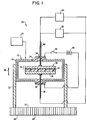
- a nickel-hydrogen battery system 20 of the type with which the invention is concerned includes a cell 22 provided with a pressure vessel 24 and an electrode stack 26 within the pressure vessel.
- the electrode stack 26, includes a positive electrode 28, a negative electrode 30, and a porous separator 32 which also serves as an electrolyte reservoir for storing excess electrolyte within the electrode stack 26.
- the porous separator 32 may be composed of zirconia, asbestos, plastic, or the like.
- the positive electrode 28 includes electrochemically active nickel hydroxide and electrically conductive material having a resistivity less than approximately 0.1 ohm/cm.
- the negative electrode 30 is of a material which catalyses the oxidation and reduction of hydrogen gas and, in typical fashion, the electrolyte is a solution of potassium hydroxide (KOH).
- the cell 22 also has electrical lead throughs 34 and 36 through which negative and positive electrical leads 38 and 40 pass respectively.
- a suitable electrically energized heater jacket 42 overlies the pressure vessel 24.
- heating elements within the heater jacket 42 can be energized by a suitable source 46 of EMF for heating the cell 22.
- the cell 22 is thermally connected to an optical space radiator (OSR) 48 via a thermally conductive sleeve 50.
- the sleeve 50 is mounted on one side 52 of the OSR 48 and slidably envelops an outer peripheral surface of the heater jacket 42 of the cell 22.
- a side 60 of the OSR 48 opposite side 52 faces black space.
- the cell is continuously cooled by the OSR and its temperature is determined by bucking the OSR with the heater jacket 42.
- Cell 22 is also suitably subjected to a source of refrigeration 70.
- a solar array 62 is the primary power source indicated for recharging the cell 22 and a typical load 64 is indicated for the discharge cycle of the cell.
- the source of refrigeration 70 in this instance, is the space environment.
- FIG. 2 illustrates a typical operation in accordance with the invention.
- the temperature of the cell 22 rises rapidly over the course of a 72 minute eclipse discharge to a temperature of approximately 34°C. This represents the customary temperature increase which occurs whenever a battery is being discharged. Cooling is effected by conduction of heat from the cell via its sleeve to the OSR which radiates to deep space. The temperature rise in Figure 2 is due to the discharge heat generation rate exceeding the OSR heat dissipation rate. Charging of the battery is then effected by means of the solar array 62.
- the temperature of the cell 22 decreases as a) the recharge rate is typically less than 20% of the discharge rate, b) battery operates endothermically during much of recharge and c) the OSR dissipates heat faster than the battery generates heat until a minimum temperature is reached between five and six hours after charging was initiated.
- the benefit of the invention is achieved by allowing the temperature to decline in such a manner that at the end of a charging process the cell 22 is at a temperature which is lower than that at which discharge begins.
- the temperature of the cell is again raised to a temperature which is preferably within the range of -10°C to +10°C. This temperature rise is achieved by closure of the switch 44 to energize the heater jacket 42. Approximately 22 hours after charging began, the cell 22 is ready for discharge.
- the capacity of the nickel hydroxide positive electrode is limited by the ability to charge the nickel electrode due to the competition between the parasitic electrolysis reaction (1) and the useful recharge reaction (2).
- 20H ⁇ 1/2 02(g) + H20 + 2e ⁇ (1)
- Ni(OH)2 + OH ⁇ NiOOH + H20 + e ⁇ (2)
- the recharging temperature is in the range or + 10°C to 30°C and the discharging temperature is in the range of -10°C to +50°C.
- the effect of the two temperatures is to promote the recharge reaction over the electrolysis reaction by low temperature recharge while promoting cell discharge by the elevated discharge temperature.
- the negative electrode should have a columbic capacity sized to balance the increased capacity of the positive electrode when the battery is charged at a temperature T1 between approximately +10°C and -30°C which is lower than a temperature T2, in the range of approximately -10°C to +5°C, at which discharge begins.
- Nickel hydrogen batteries typically employ highly porous Zr02 woven ceramic separators which (a) allow rapid diffusion of the electrolyte and (b) contain a large electrolyte quantity that acts to buffer concentration changes. Nickel hydrogen batteries thus exhibit thermally induced capacity enhancement.
- Conventional solid negative electrode batteries typically employ fined pored thin polymeric separators such as Pellon® brand (nylon) or Cellgard® brand (polypropylene) which may tend to inhibit electrolyte diffusion and contain a minimum amount of buffering electrolyte.
- Pellon® brand nylon
- Cellgard® brand polypropylene
- preferred separators of woven cloth, plastic felts and mats of ZrO2 and Al203 felt are highly porous with a porosity in the range of approximately 10% to 50% bulk density.
- thermally induced capacity enhancement can be achieved in batteries which employ a nickel hydroxide positive electrode and condensed phase negative electrodes such as metal hydride, zinc, iron and cadmium.
- This enhancement is obtained by optimizing the design of the batteries by increasing the amount of negative active material to accommodate the increased positive electrode capacity.
- a further benefit is achieved by selection of highly porous separators, that is, with large porosity in the approximate range of 10% to 50% bulk density to promote electrolyte concentration balancing between the opposing electrodes during recharge. It is also considered desirable to include an additional quantity of electrolyte in the positive electrode and/or separator to buffer local concentration changes during recharge.
- an application of the present invention is in an outer space environment wherein the lower temperature ranges required for charging the battery are readily available.
- a low temperature environment may be provided by conventional refrigeration techniques. This may be indicated by the refrigeration source 70 to provide the low temperature environment for recharging the cell 22.
Landscapes
- Engineering & Computer Science (AREA)
- Manufacturing & Machinery (AREA)
- Chemical & Material Sciences (AREA)
- Chemical Kinetics & Catalysis (AREA)
- Electrochemistry (AREA)
- General Chemical & Material Sciences (AREA)
- Automation & Control Theory (AREA)
- Physics & Mathematics (AREA)
- Electromagnetism (AREA)
- Secondary Cells (AREA)
- Battery Electrode And Active Subsutance (AREA)
- Charge And Discharge Circuits For Batteries Or The Like (AREA)
Abstract
Description
- The present invention relates generally to a nickel-hydrogen battery and to a method of operation of such a battery, and more particularly, a nickel-hydrogen battery and to the method of recharging such a battery at a temperature which is substantially lower than the temperature at which discharge is performed. The invention also relates to the construction of any battery using a nickel hydroxide positive electrode which is so operated including batteries with negative electrodes of metal hydride, zinc, iron or cadmium. The invention has application for space purposes but is also of benefit for non-space purposes such as the powering of laptop computers and cellular telephones.
- It is well recognized that optimum performance for nickel hydrogen spacecraft batteries requires that their temperature be controlled in the range of +20°C to -10°C. Higher temperatures lead to lowered capacity due to the early on-set of the parasitic electrolysis reaction, e.g.,
2OH⁻ = 1/2 0₂ + H₂0 + 2e⁻ ( 1 )
Reaction (1) has been recognized in the prior art to reduce capacity as the operating temperature of the battery is increased. A key to the present invention has been the recognition that the critical temperature is that at which the battery is recharged and reaction (1) competes with the normal recharge reaction, e.g.,
Ni (0H)₂ + OH⁻ = NiOOH + H₂0 + e⁻ (2)
- Lower temperatures on the other hand have been found to lead to batteries which fail to operate. The reasons for this failure, prior to the present invention, were unclear as the freezing point of the electrolyte (-61°C) is well below the minimum operation temperature. The second key to the present invention has been the recognition that the lower temperature limit is due to a limitation in the ability of the battery to sustain high rate discharge required in satellites situated in a geosynchronous orbit (e.g., ∼C/1.5) as opposed to the lower rate recharge (e.g., ∼C/10).
- Typical of the prior art as it relates to charging and discharging nickel batteries is U.S. Patent No. 4,680,241 to Dyer. The Dyer patent concerns a method for partially or fully restoring the lost capacities of nickel batteries. In this instance, a nickel battery is cycled at least 10 times, with each cycle including a discharging step during which the capacity achieved at the end of the previous cycle is reduced by at least 5 percent, and a charging step. The charging rate employed during the charging step is greater than about C/10 per hour. Moreover, while the ratio of the amount of charge delivered to the battery during the charging step of each cycle to the amount of charge withdrawn from the battery during the previous cycle is greater than one, this ratio is chosen so that the temperature of the electrolyte of the battery does not exceed about 30°C.
- It is clear, however, that the Dyer patent does not address the particular problem which the present invention is intended to solve.
- It was in light of the state of the technology as just described that the present invention has been conceived and is now reduced to practice.
- The present invention relates to a method of operating a nickel-hydrogen battery which increases its charge capacity. The method comprises the step of completing the recharging process for the battery at a temperature T₁, in the range of approximately -10°C down to -30°C which is lower than a temperature T₂, in the range of approximately -10°C to +5°C, at which discharge customarily begins. At the onset of the recharge operation the temperature may be in the range of +25°C to + 40°C. However, as recharge proceeds, the temperature is caused to fall to the range of -10°C to -30°C which is optimum for full recharge. The temperature T₁ is preferably chosen to maximize the extent of the reaction represented by the equation:
Ni (OH)₂ + OH⁻ = NiOOH + H₂0 + e⁻ (2)
versus the reaction represented by the equation:
20H⁻ = 1/2 0₂ + H₂0 + 2e⁻ (1)
Subsequently, it is desirable to heat the battery to the temperature T₂ in readiness for discharge. A preferred recharge temperature is less than approximately -10°C. The battery includes a positive electrode which may include electrochemically active Ni(OH)₂ (possibly mixed with CO(OH)₂) and electrically conductive material having a resistivity less than approximately 0.1 ohm-cm, a negative electrode which is of a material which catalyzes the oxidation and reduction of H₂, and an electrolyte which is a solution of KOH (typically 20% to 40% by weight). - The foregoing principle can be applied to any battery which uses a nickel hydroxide positive electrode, specifically, to such batteries which have a condensed phase negative electrode such as metal hydride, zinc, iron and cadmium.
- Accordingly, the invention seeks to provide a unique method for increasing the capacity of a nickel-hydrogen battery.
- The method of increasing the capacity of a nickelhydrogen battery may be achieved by charging at a temperature, or within a range of temperatures, which is lower than the temperature at which discharge begins.
- The invention may provide such an improved method in which the extent of the reaction represented by the equation 20H⁻ = 1/2 0₂ + H₂0 + 2e⁻
is maximized in relation to the reaction represented by the equation Ni(OH)₂ + OH⁻ = NiOOH + H₂0 + e⁻. - The invention according to another aspect may provide a capacity enhanced battery using a nickel hydroxide positive electrode and a condensed phase negative electrode of metal hydride, zinc, iron, or cadmium.
- Other and further features, advantages, and benefits of the invention will become apparent in the following description taken in conjunction with the following drawings. It is to be understood that the foregoing general description and the following detailed description are exemplary and explanatory but are not to be restrictive of the invention. The accompanying drawings which are incorporated in and constitute a part of this invention, illustrate one of the embodiments of the invention and, together with the description, serve to explain the principles of the invention in general terms. Like numerals refer to like parts throughout the disclosure.
- Figure 1 is a diagrammatic representation of a battery system embodying the present invention and including a cross section view of a cell of a nickel-hydrogen battery used with the system,
- Figure 2 is a graph depicting the operation of a cell in accordance with the invention, presenting various parameters over the course of time, and
- Figure 3 is a graph presenting nickel-hydrogen cell capacity versus isothermal charge and discharge temperature.
- As shown in Figure 1, a nickel-
hydrogen battery system 20 of the type with which the invention is concerned includes acell 22 provided with apressure vessel 24 and anelectrode stack 26 within the pressure vessel. Theelectrode stack 26, in turn, includes apositive electrode 28, anegative electrode 30, and aporous separator 32 which also serves as an electrolyte reservoir for storing excess electrolyte within theelectrode stack 26. Theporous separator 32 may be composed of zirconia, asbestos, plastic, or the like. Thepositive electrode 28 includes electrochemically active nickel hydroxide and electrically conductive material having a resistivity less than approximately 0.1 ohm/cm. Thenegative electrode 30 is of a material which catalyses the oxidation and reduction of hydrogen gas and, in typical fashion, the electrolyte is a solution of potassium hydroxide (KOH). - The
cell 22 also haselectrical lead throughs - A suitable electrically energized
heater jacket 42 overlies thepressure vessel 24. By closure of aswitch 44, heating elements within theheater jacket 42 can be energized by asuitable source 46 of EMF for heating thecell 22. - The
cell 22 is thermally connected to an optical space radiator (OSR) 48 via a thermallyconductive sleeve 50. Thesleeve 50 is mounted on oneside 52 of theOSR 48 and slidably envelops an outer peripheral surface of theheater jacket 42 of thecell 22. A side 60 of the OSR 48opposite side 52 faces black space. The cell is continuously cooled by the OSR and its temperature is determined by bucking the OSR with theheater jacket 42.Cell 22 is also suitably subjected to a source ofrefrigeration 70. - On a spacecraft which is the intended user for the
cell 22, asolar array 62 is the primary power source indicated for recharging thecell 22 and atypical load 64 is indicated for the discharge cycle of the cell. The source ofrefrigeration 70, in this instance, is the space environment. - Figure 2 illustrates a typical operation in accordance with the invention. As seen therein, as a discharging operation ensues, the temperature of the
cell 22 rises rapidly over the course of a 72 minute eclipse discharge to a temperature of approximately 34°C. This represents the customary temperature increase which occurs whenever a battery is being discharged. Cooling is effected by conduction of heat from the cell via its sleeve to the OSR which radiates to deep space. The temperature rise in Figure 2 is due to the discharge heat generation rate exceeding the OSR heat dissipation rate. Charging of the battery is then effected by means of thesolar array 62. As charging proceeds, the temperature of thecell 22 decreases as a) the recharge rate is typically less than 20% of the discharge rate, b) battery operates endothermically during much of recharge and c) the OSR dissipates heat faster than the battery generates heat until a minimum temperature is reached between five and six hours after charging was initiated. The benefit of the invention is achieved by allowing the temperature to decline in such a manner that at the end of a charging process thecell 22 is at a temperature which is lower than that at which discharge begins. Thus when charging ends approximately 17 hours after it began, at the beginning of a quiescent period, the temperature of the cell is again raised to a temperature which is preferably within the range of -10°C to +10°C. This temperature rise is achieved by closure of theswitch 44 to energize theheater jacket 42. Approximately 22 hours after charging began, thecell 22 is ready for discharge. - In Figure 3, a plot is provided of nickel-hydrogen cell capacity versus the isothermal charge and discharge temperature. As can be seen in Figure 3, the delivered cell capacity peaks at a temperature between 0°C and +10°C. Also provided in the figure is a datum in which the cell is charged at -20°C and discharged at +20°C. As can be seen, this bimodal temperature operation leads to the highest cell capacity. The interpretation of this result is that the kinetics of cell discharge are improved at high temperature whereas the kinetics of cell charging are more optimum at lower temperature.
- In a second test, a cell was (a) charged and discharged at -20°C, (b) charged at -20°C, allowed to stand at open circuit for 4 hours and then discharged at -20°C and (c) charged at -20°C, warmed to +10°C and discharged. Case (c) operated in a fashion comparable to case (a) . The interpretation of these results is as follows:
- (i) in case (a), the internal heating of the cell was sufficient to raise its temperature to a point at which it was operable at an abnormally low temperature;
- (ii) in case (b), the open circuit period led to a decrease in the cell internal temperature to a point at which the cell could no longer support a high rate of operation; and
- (iii) in case (c), the cold recharge capacity which could not be extracted in case (b) was available once the temperature was increased to a point at which the battery was operable.
- As described above, the capacity of the nickel hydroxide positive electrode is limited by the ability to charge the nickel electrode due to the competition between the parasitic electrolysis reaction (1) and the useful recharge reaction (2).
20H⁻ = 1/2 0₂(g) + H₂0 + 2e⁻ (1)
Ni(OH)₂ + OH⁻ = NiOOH + H₂0 + e⁻ (2)
- In the referenced application a method for increasing the capacity of nickel hydrogen batteries is described in which the recharging temperature is in the range or + 10°C to 30°C and the discharging temperature is in the range of -10°C to +50°C. The effect of the two temperatures is to promote the recharge reaction over the electrolysis reaction by low temperature recharge while promoting cell discharge by the elevated discharge temperature.
- The same principle should allow the capacity enhancement of any battery which uses a nickel hydroxide positive electrode and a negative electrode such as metal hydride, zinc, iron, and cadmium. In fact, however, it has been found that the capacity of conventionally built solid negative electrode batteries is not materially increased by practising the previously described bimodal temperature operation. Conventional batteries fail to demonstrate a thermally induced capacity enhancement due (1) to failure to provide sufficient negative solid or, at least, condensed phase active material to accommodate the enhanced positive electrode capacity, and (2) to use of a separator design which does not allow for a ready balancing of the local electrode concentration at the positive electrode as the battery is recharged.
- Thus, as to (1), additional metal alloy, zinc, iron, cadmium, or the like, must be included in a cell to realise a thermally induced capacity increase. This is not an issue for nickel hydrogen as the positive electrode intrinsically creates the required negative discharge state active material (H₂0) as it is charged. For the condensed phase materials, however, the mass of the negative electrode must be enlarged proportionately to the increased capacity of the positive electrode. Specifically, the negative electrode should have a columbic capacity sized to balance the increased capacity of the positive electrode when the battery is charged at a temperature T1 between approximately +10°C and -30°C which is lower than a temperature T₂, in the range of approximately -10°C to +5°C, at which discharge begins.
- The material is then converted to H2 by the negative recharge reaction (3):
2H₂0 + 2e⁻ = H2(g) + 20H⁻ (3)
- As to the separator design, it is well recognized that the charge acceptance of the nickel hydroxide electrode decreases as the KOH(aq) electrolyte concentration decreases. This occurs locally at the positive electrode when water is formed during recharge. The degree to which the electrolyte concentration decreases is a function of its viscosity (which increases as temperature decreases thereby decreasing electrolyte diffusion) and the separator. Nickel hydrogen batteries typically employ highly porous Zr0₂ woven ceramic separators which (a) allow rapid diffusion of the electrolyte and (b) contain a large electrolyte quantity that acts to buffer concentration changes. Nickel hydrogen batteries thus exhibit thermally induced capacity enhancement. Conventional solid negative electrode batteries typically employ fined pored thin polymeric separators such as Pellon® brand (nylon) or Cellgard® brand (polypropylene) which may tend to inhibit electrolyte diffusion and contain a minimum amount of buffering electrolyte.
- In contrast, preferred separators of woven cloth, plastic felts and mats of ZrO₂ and Al₂0₃ felt are highly porous with a porosity in the range of approximately 10% to 50% bulk density.
- In summary, thermally induced capacity enhancement can be achieved in batteries which employ a nickel hydroxide positive electrode and condensed phase negative electrodes such as metal hydride, zinc, iron and cadmium. This enhancement is obtained by optimizing the design of the batteries by increasing the amount of negative active material to accommodate the increased positive electrode capacity. A further benefit is achieved by selection of highly porous separators, that is, with large porosity in the approximate range of 10% to 50% bulk density to promote electrolyte concentration balancing between the opposing electrodes during recharge. It is also considered desirable to include an additional quantity of electrolyte in the positive electrode and/or separator to buffer local concentration changes during recharge.
- As previously stated, an application of the present invention is in an outer space environment wherein the lower temperature ranges required for charging the battery are readily available. For non-space applications, such as for use in laptop computers and cellular telephones, one skilled in the art will appreciate that a low temperature environment may be provided by conventional refrigeration techniques. This may be indicated by the
refrigeration source 70 to provide the low temperature environment for recharging thecell 22. - While preferred embodiments of the invention have been disclosed in detail, it should be understood by those skilled art that various other modifications may be made to the illustrated embodiment without departing from the scope of the invention as described in the specification and defined in the appended claims.
Claims (22)
- A battery, comprising a nickel hydroxide positive electrode, an electrolyte, a condensed phase negative electrode having a columbic capacity sized to balance the increased capacity of the positive electrode when the battery is charged at a temperature T₁ between approximately +10°C and -30°C which is lower than a temperature T₂, in the range of approximately -10°C to +5°C, at which discharge begins.
- A battery as claimed in claim 1, wherein temperature T₁ is chosen to maximize the extent of the reaction represented by the equation:
2 OH⁻ = 1/2 0₂ + H₂0 + 2 e⁻
versus the reaction represented by the equation:
Ni(OH)₂ + OH⁻ = NiOOH + H₂0 + e⁻ .
- A battery as claimed in claim 1 or 2, wherein the positive electrode includes electrochemically active Ni(OH)₂ and electrically conductive material having a resistivity less than approximately 0.1 ohm-cm, wherein the negative electrode is of a material which catalyzes the oxidation and reduction of H₂, and wherein the electrolyte is a solution of KOH .
- A battery as claimed in any one of the preceding claims, wherein the negative electrode is a condensed phase material selected from the group consisting of metal hydride, zinc, iron, and cadmium.
- A battery as claimed in any one of claims 1 to 3, wherein the negative electrode is hydrogen.
- A battery as claimed in any one of the preceding claims, wherein the electrolyte is a material selected from the group consisting of ZrO₂, woven cloth, plastic felts, and mats, and Al₂0₃ felt.
- A battery as claimed in any one of the preceding claims, including a source of refrigeration for cooling the battery to a temperature T₁ in the range between +10°C and -30°C.
- A method of operating a battery comprising a nickel hydroxide positive electrode and an electrolyte comprising the step of charging the battery at a temperature T₁ between approximately +10°C and -30°C which is lower than a temperature T₂, in the range of approximately -10°C to +5°C, at which discharge begins; and providing a condensed phase negative electrode having a columbic capacity sized to balance the increased capacity of the positive electrode when the battery is charged at the temperature T₁.
- A method of operating a battery as claimed in claim 8 wherein temperature T₁ is chosen to maximize the extent of the reaction represented by the equation:
2 OH⁻ = 1/2 0₂ + H₂0 + 2e⁻
versus the reaction represented by the equation:
Ni (OH)₂ + OH⁻ = NiOOH + H₂0⁻ + e⁻.
- A method of operating a battery as claimed in claim 8 or 9, wherein the positive electrode includes electrochemically active Ni(OH)₂ and electrically conductive material having a resistivity less than approximately 0.1 ohm-cm, wherein the negative electrode is of a material which catalyzes the oxidation and reduction of H₂ and wherein the electrolyte is a solution of KOH.
- A method of operating a battery as claimed in any one of claims 8 to 10, wherein the negative electrode is a condensed phase material selected from the group consisting of metal hydride, zinc, iron, and cadmium.
- A method of operating a battery as claimed in any one of claims 8 to 10, wherein the negative electrode is hydrogen.
- A method of operating a battery as claimed in any one of claims 8 to 12, wherein the electrolyte is a material selected from the group consisting of ZrO₂, woven cloth, plastic felts, and mats, and Al₂0₃ felt.
- A method of operating a nickel-hydrogen battery which includes a positive electrode, a negative electrode, and an electrolyte, the battery being less than fully charged, the method comprising the step of:
(a) reaching a full state of charge in a battery at a temperature T₁ between approximately -10°C and -30°C which is lower than a temperature T₂, in the range of approximately -10°C to +5°C, at which discharge begins. - A method of operating a nickel-hydrogen battery as claimed in claim 14, wherein temperature T1 is chosen to maximize the extent of the reaction represented by the equation:
H₂0 + 2e⁻ = OH⁻ + °0₂
versus the reaction represented by the equation:
Ni (OH)₂ + OH⁻ = NiOOH + H₂0 + e⁻.
- A method of operating a nickel-hydrogen battery as claimed in claim 14 or 15 including the step, after step (a), of:
(b) heating the battery to the temperature T₂ in readiness for discharge. - A method of operating a nickel-hydrogen battery as claimed in any one of claims 14 to 16, wherein the temperature of the battery before the completion of recharge is less than approximately -10°C.
- A method of operating a nickel-hydrogen battery as claimed in any one of claims 14 to 17, wherein the positive electrode includes electrochemically active Ni(OH)₂ and electrically conductive material having a resistivity less than approximately 0.1 ohmcm, wherein the negative electrode is of a material which catalyzes the oxidation and reduction of H₂ and wherein the electrolyte is a solution of KOH.
- A method of operating a nickel-hydrogen battery which includes a positive electrode, a negative electrode, and an electrolyte, the method comprising the steps of (a) discharging the battery, causing its temperature to rise to an elevated level, (b) charging the battery while the temperature thereof is at the elevated level, (c) cooling the battery, and (d) reaching a full state of charge in the battery when the battery is at a temperature T1 between approximately -10°C and -30°C which is lower than a temperature T₂, in the range of approximately -10°C to +5°C, at which discharge begins.
- A method of operating a nickel-hydrogen battery as claimed in claim 19, wherein temperature T1 is chosen to maximize the extent of the reaction represented by the equation:
H₂0 + 2e⁻ = OH⁻ + °0₂
versus the reaction represented by the equation:
Ni (OH)₂ + OH⁻ = NiOOH + H₂0 + e⁻.
- A method of operating a nickel-hydrogen battery as claimed in claim 19 or 20 including the step, after step (e), of: (f) heating the battery to the temperature T₂ in readiness for discharge.
- A method of operating a nickel-hydrogen battery as claimed in any one of claims 19 to 21, wherein the temperature of the battery before the completion of recharge is less than approximately -10°C.
Applications Claiming Priority (4)
| Application Number | Priority Date | Filing Date | Title |
|---|---|---|---|
| US182224 | 1994-01-14 | ||
| US08/182,224 US5395706A (en) | 1994-01-14 | 1994-01-14 | Satellite battery thermal/capacity design |
| US08/340,789 US5429888A (en) | 1994-01-14 | 1994-11-21 | Battery recharging technique |
| US340789 | 1994-11-21 |
Publications (1)
| Publication Number | Publication Date |
|---|---|
| EP0665604A1 true EP0665604A1 (en) | 1995-08-02 |
Family
ID=26877909
Family Applications (1)
| Application Number | Title | Priority Date | Filing Date |
|---|---|---|---|
| EP19950300189 Withdrawn EP0665604A1 (en) | 1994-01-14 | 1995-01-12 | Battery and method of operation of a battery |
Country Status (3)
| Country | Link |
|---|---|
| US (1) | US5429888A (en) |
| EP (1) | EP0665604A1 (en) |
| JP (1) | JPH07282810A (en) |
Families Citing this family (6)
| Publication number | Priority date | Publication date | Assignee | Title |
|---|---|---|---|---|
| KR100212180B1 (en) * | 1996-03-15 | 1999-08-02 | 윤덕용 | Activation treatment method of ni/mh secondary battery by hot charging |
| US5617006A (en) * | 1996-04-24 | 1997-04-01 | Space Systems/Loral, Inc. | Recharge profile for spacecraft NI/H2 batteries |
| US6054842A (en) * | 1998-07-24 | 2000-04-25 | The Boeing Company | Method for improving battery discharge performance |
| US6383679B1 (en) | 1999-11-10 | 2002-05-07 | Space Systems/Loral, Inc. | Self-tuning charge controller for nickel hydrogen batteries |
| RU2313160C1 (en) * | 2006-03-22 | 2007-12-20 | Федеральное государственное унитарное предприятие "Научно-производственное объединение прикладной механики им. академика М.Ф. Решетнева" | Method for making nickel-hydrogen storage battery ready for full-time service in power supply system of artificial earth satellite |
| DE102012205396A1 (en) | 2012-04-03 | 2013-10-10 | Robert Bosch Gmbh | Method for the resistive cell compensation of battery cells of a battery, a battery controlled according to the method and a motor vehicle |
Citations (3)
| Publication number | Priority date | Publication date | Assignee | Title |
|---|---|---|---|---|
| EP0043634A1 (en) * | 1980-06-30 | 1982-01-13 | International Telecommunications Satellite Organisation | Metal-oxide-hydrogen cell |
| JPH0322365A (en) * | 1989-06-20 | 1991-01-30 | Matsushita Electric Ind Co Ltd | Formation for sealed alkaline storage battery using hydrogen storage alloy negative electrode |
| JPH05151990A (en) * | 1991-11-26 | 1993-06-18 | Matsushita Electric Ind Co Ltd | Chemical formation method for sealed type nickel-hydrogen storage battery |
Family Cites Families (2)
| Publication number | Priority date | Publication date | Assignee | Title |
|---|---|---|---|---|
| US4680241A (en) * | 1983-11-29 | 1987-07-14 | American Telephone And Telegraph Company, At&T Bell Laboratories | Method for restoring the lost capacity of nickel batteries and batteries formed thereby |
| US4567119A (en) * | 1984-03-12 | 1986-01-28 | Hughes Aircraft Company | Nickel-hydrogen bipolar battery |
-
1994
- 1994-11-21 US US08/340,789 patent/US5429888A/en not_active Expired - Lifetime
-
1995
- 1995-01-12 EP EP19950300189 patent/EP0665604A1/en not_active Withdrawn
- 1995-01-17 JP JP459995A patent/JPH07282810A/en active Pending
Patent Citations (3)
| Publication number | Priority date | Publication date | Assignee | Title |
|---|---|---|---|---|
| EP0043634A1 (en) * | 1980-06-30 | 1982-01-13 | International Telecommunications Satellite Organisation | Metal-oxide-hydrogen cell |
| JPH0322365A (en) * | 1989-06-20 | 1991-01-30 | Matsushita Electric Ind Co Ltd | Formation for sealed alkaline storage battery using hydrogen storage alloy negative electrode |
| JPH05151990A (en) * | 1991-11-26 | 1993-06-18 | Matsushita Electric Ind Co Ltd | Chemical formation method for sealed type nickel-hydrogen storage battery |
Non-Patent Citations (3)
| Title |
|---|
| PATENT ABSTRACTS OF JAPAN vol. 015, no. 147 (E - 1055) 12 April 1991 (1991-04-12) * |
| PATENT ABSTRACTS OF JAPAN vol. 017, no. 535 (E - 1439) 27 September 1993 (1993-09-27) * |
| S.W.DONLEY: "STUDY OF NICKEL HYDROGEN BATTERY DISCHARGE PERFORMANCE AFTER CHARGE AND STAND AT WARM TEMPERATURE", PROCEEDINGS OF THE 27TH INTERSOCIETY ENERGY CONVERSION ENGINEERING CONFERENCE, vol. P259, no. 1, 3 August 1992 (1992-08-03), SAN DIEGO, pages 1.487 - 1.494, XP000402790 * |
Also Published As
| Publication number | Publication date |
|---|---|
| US5429888A (en) | 1995-07-04 |
| JPH07282810A (en) | 1995-10-27 |
Similar Documents
| Publication | Publication Date | Title |
|---|---|---|
| US5439756A (en) | Electrical energy storage device and method of charging and discharging same | |
| EP0665603B1 (en) | Bimodal electric vehicle battery system | |
| US5395706A (en) | Satellite battery thermal/capacity design | |
| CA2157930C (en) | Sealed rechargeable battery | |
| US5429888A (en) | Battery recharging technique | |
| US4395469A (en) | Low pressure nickel hydrogen battery | |
| US6388427B1 (en) | Battery temperature derivative charging | |
| Okamura | A basic study on power storage capacitor systems | |
| US6054842A (en) | Method for improving battery discharge performance | |
| US5584892A (en) | Process for producing nickel electrode having lightweight substrate | |
| Takahashi et al. | Eight years of experience with valve-regulated batteries for automotive use | |
| Dunbar | High performance nickel metal hydride batteries | |
| JP7355772B2 (en) | Manufacturing method of nickel metal hydride storage battery | |
| Sequeira et al. | Lead-acid battery storage | |
| US5626987A (en) | Hydridable material for the negative electrode in a nickel-metal hydride storage battery | |
| Smith et al. | High energy density lithium rechargeable batteries for underwater vehicle propulsion | |
| Spiers | Battery issues | |
| JP4134873B2 (en) | Charging method and charger for sealed alkaline storage battery | |
| Gibbard | Nickel metal hydride battery technology | |
| Stadnick et al. | 26 percent potassium hydroxide electrolyte for long-term nickel-hydrogen geosynchronous missions | |
| Coates et al. | Nickel-metal hydride and silver-metal hydride batteries for aerospace applications | |
| Anderman et al. | Performance of a 100 Ah common vessel monoblock nickel-cadmium battery | |
| MOSELEY et al. | weight, Whkg-1. Generally, a high coulombic efficiency (charge out: charge in) | |
| JP2006032253A (en) | Sealed storage battery | |
| Noren | COMPARISON OF ALTERNATE POWER SOURCES FOR THE MX MISSILE SYSTEM |
Legal Events
| Date | Code | Title | Description |
|---|---|---|---|
| PUAI | Public reference made under article 153(3) epc to a published international application that has entered the european phase |
Free format text: ORIGINAL CODE: 0009012 |
|
| AK | Designated contracting states |
Kind code of ref document: A1 Designated state(s): DE FR GB IT |
|
| 17P | Request for examination filed |
Effective date: 19951002 |
|
| 17Q | First examination report despatched |
Effective date: 19991129 |
|
| RAP3 | Party data changed (applicant data changed or rights of an application transferred) |
Owner name: SPACE SYSTEMS / LORAL, INC. |
|
| RTI1 | Title (correction) |
Free format text: METHOD OF OPERATION OF A BATTERY |
|
| GRAH | Despatch of communication of intention to grant a patent |
Free format text: ORIGINAL CODE: EPIDOS IGRA |
|
| RTI1 | Title (correction) |
Free format text: METHOD OF OPERATION OF A BATTERY |
|
| RTI1 | Title (correction) |
Free format text: METHOD OF OPERATION OF A BATTERY |
|
| STAA | Information on the status of an ep patent application or granted ep patent |
Free format text: STATUS: THE APPLICATION IS DEEMED TO BE WITHDRAWN |
|
| 18D | Application deemed to be withdrawn |
Effective date: 20030820 |