EP0665109B1 - Ink container having plural porous members for storing ink and ink jet apparatus having said ink container - Google Patents
Ink container having plural porous members for storing ink and ink jet apparatus having said ink container Download PDFInfo
- Publication number
- EP0665109B1 EP0665109B1 EP95101222A EP95101222A EP0665109B1 EP 0665109 B1 EP0665109 B1 EP 0665109B1 EP 95101222 A EP95101222 A EP 95101222A EP 95101222 A EP95101222 A EP 95101222A EP 0665109 B1 EP0665109 B1 EP 0665109B1
- Authority
- EP
- European Patent Office
- Prior art keywords
- ink
- porous members
- ink container
- tank
- ink tank
- Prior art date
- Legal status (The legal status is an assumption and is not a legal conclusion. Google has not performed a legal analysis and makes no representation as to the accuracy of the status listed.)
- Expired - Lifetime
Links
Images


Classifications
-
- B—PERFORMING OPERATIONS; TRANSPORTING
- B41—PRINTING; LINING MACHINES; TYPEWRITERS; STAMPS
- B41J—TYPEWRITERS; SELECTIVE PRINTING MECHANISMS, i.e. MECHANISMS PRINTING OTHERWISE THAN FROM A FORME; CORRECTION OF TYPOGRAPHICAL ERRORS
- B41J2/00—Typewriters or selective printing mechanisms characterised by the printing or marking process for which they are designed
- B41J2/005—Typewriters or selective printing mechanisms characterised by the printing or marking process for which they are designed characterised by bringing liquid or particles selectively into contact with a printing material
- B41J2/01—Ink jet
- B41J2/17—Ink jet characterised by ink handling
- B41J2/175—Ink supply systems ; Circuit parts therefor
- B41J2/17503—Ink cartridges
- B41J2/17513—Inner structure
Definitions
- the present invention relates to an ink tank which is an ink container and, more particularly, to an ink tank serving as an ink container for storing ink used as a recording agent (liquid) in recording apparatuses, such as writing implements, ink jet recording apparatuses, copier machines, or facsimiles.
- a recording agent liquid
- FIG. 1 shows an example of such an apparatus IJRA having a recording unit IJC, having a recording head serving as recording means for recording on a recording medium P and an ink tank serving as a liquid storage unit, disposed on a printer carriage HC.
- the carriage HC scans the recording medium P in the directions a and b, and a platen PL driven by a motor transports the recording medium.
- the recording unit constructions in which the recording head and the ink tank are formed as one unit, and in which the recording head is separable from the ink tank so that only the ink tank is replaced when the ink is used up, have been proposed.
- size, and therefore the volume, of the ink tank is necessarily limited.
- the amount of ink available to the recording means for recording information should not be limited by the size of the apparatus. Therefore, it is important to effectively use the volume available, and it is necessary that as much of the ink in the container as possible be used.
- a porous member In the ink tank, a porous member, typified by a sponge, has been widely used in the past as means for holding ink. Such a porous member exerts a capillary force on the ink, and by varying the size of the pores or the compressibility of the porous member, it is possible to vary the capillary force as desired.
- an ink holding force for holding the pressure balance required in the recording head in a wide range.
- the tank construction can be simplified, making it possible to manufacture the apparatus at a relatively low cost.
- porous members which store ink by the above-described capillary force.
- a minimum requirement for such a member is that the internal spaces be interconnected.
- the greater the total volume of the internal spaces of the porous member with respect to the internal volume of the structural member (that is, the ink tank) in which the porous member is housed the greater the amount of ink which can be held and the higher the space-use efficiency of the ink tank.
- a sponge is excellent as an ink-storing porous member, because the effective porosity of a typical sponge can reach 70% or thereabouts.
- Resin-material sponges in particular, are applied to wide uses, and various resin materials are commercially available. Thus, such a sponge is excellent in that the price of the material is low.
- the ink head pressure in the recording head be lower than the atmospheric pressure.
- the ink head pressure is made lower by 0 to 150 mmAq than the atmospheric pressure by virtue of the ink holding force of the porous member.
- the ink head pressure be made lower than atmospheric pressure by 30 mmAq or more in order to prevent ink from leaking to the outside from the ink tank.
- a fine capillary structure with 40 to 100 cells (pores) per inch is necessary, with the exact number depending on the type of ink stored.
- a sponge of such a small porous size would have an inordinately high cost. Therefore, the necessary small-size porous member is provided in the ink tank by the method shown in Fig. 2.
- a porous member 2 having a typical structure in that the number of pores 3 per inch is 30 to 50/inch, as shown in Fig. 2(a) is compressed from 3 to 5 times (that is, the volume is decreased 1/3 to 1/5) as shown in Fig. 2(b).
- the compressed porous member is then inserted into an ink tank 1 as shown in Fig. 2(c), thereby providing in the ink tank a porous member with the required 40 to 100 cells/inch.
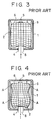
- Fig. 3 is a schematic view of an ink tank into which a porous member has been compressed and inserted by the above-described method, wherein the compression state is represented in grid form.
- Reference numeral 1 denotes an ink tank;
- reference numeral 2 denotes a porous member;
- reference numeral 4 denotes an ink outlet for guiding the ink I stored inside the ink tank to the recording head or the like;
- reference numeral 5 denotes an air connection port or vent;
- reference numeral 6 denotes a rib for vapor-liquid replacement;
- reference numeral 8 denotes an ink exit member having a tubular configuration for guiding the stored ink to the outside.
- compression of the porous member 2 is increased by pressing and deforming the porous member 2 in the vicinity of the ink outlet 4 so that the ink is concentrated and operational efficiency is improved.
- Fig. 4 is a schematic view of an ink tank having the same construction as that of Fig. 3, but illustrating a case in which the porous member 2 has been loaded in the ink tank 1 with local deviations in compression. Since the porous member 2 has portions, indicated by "A" in the figure, where compression is abnormally high, and the ink is undesirably concentrated, causing the ink supply passage to be interrupted and resulting in ink being unavailable for recording because it remains inside the ink tank.
- Fig. 5 illustrates an example in which a conventional ink tank is subjected to an excessive impact.
- the sponge inside the ink tank deviates along the direction of the impact, and as a result the compression distribution is altered. This is due to the fact that the deviation of the sponge generally does not return to its original state after the impact. Further, the ink in the sponge may also be moved by the impact or the communication between the sponge and the ink outlet may be cut.
- the present invention has been are achieved in view of the above-described problems of the prior art. It is an object of present invention to solve the above-described problems and to realize an ink tank which is inexpensive and easy to manufacture, and is capable of supplying ink stably.
- an ink container for storing ink comprises an ink tank providing an enclosed space within an inner wall of said tank, and a plurality of porous members having open pores for holding ink and including a plurality of inner porous members and a plurality of outer porous members, the inner porous members being disposed within the enclosed space so as to contact and press against other inner porous members and/or outer porous members, and the outer porous members being disposed within the enclosed space so as to contact and press against the inner porous members and the inner wall of the ink tank.
- an ink jet apparatus comprises a recording head for discharging ink, the above ink container, a carriage on which the recording head and the ink container are mounted, and transport means for transporting a recording medium.
- a recording unit apparatus comprises a recording head for discharging ink and the above ink container further comprising an ink supply tube consisting of a portion projecting out of the ink tank and a portion projecting into the ink tank for supplying ink to the recording head from the ink container, wherein the recording head is integrally formed on the ink container so as to incorporate the portion of the ink supply tube projecting out of said ink tank.
- a replaceable type ink tank is used as an ink housing section for housing porous members.
- reference numeral 11 denotes an ink tank serving as an ink container
- reference numeral 20 denotes an ink jet recording head which is separable from the ink tank.
- a pres-contact member 19 is provided inside the ink tank 11.
- the press-contact member 19 forms an ink passage by a capillary force created as a result of closely contacting a filter 21 disposed in the ink outlet in the shape of a tunnel of the ink jet recording head 20.
- a member having fine fiber bundles is used.
- Reference numeral 12 denotes a porous member which is formed to be small in comparison with the internal volume of the ink tank.
- a plurality of porous members 12 are provided inside the ink tank, and fill the ink container so as to press against each other.
- a porous member disposed in the central portion of the inside of the ink tank only contacts and presses against other porous members, and a porous member disposed in the vicinity of the inner wall of the ink tank contacts and presses against both the other porous members and the inner wall of the ink tank.
- the size and shape of the porous members 12 are preferably such that a plurality of them can press against all the inner walls of the ink tank.
- the porous members 12 will be referred to as sponge cells or flake porous members.
- the ink tank has an air induction port 15 for inducting air into the interior of the container from the outside.
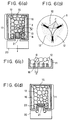
- the pressure of the interface of the sponge cell 12 with the air is equal to the atmospheric pressure. If the sponge cell 12 is sufficiently small, it is possible to fill the intricate place (the B region in Fig. 6(a)) inside the ink tank 11 with the porous members without leaving a vacancy which will otherwise be formed when a single porous member is inserted into the ink tank. Therefore, since the ink can be held by the porous members without forming a vacancy inside an ink tank having a desired internal shape, it is possible to effectively prevent ink leakage which occurs as a result of the ink remaining in said vacancy.
- each sponge cell Since each sponge cell is independent in structure, it receives a compression force nearly uniformly, and the capillary force of each sponge cell is also uniform.
- the boundary (the C region in the figure) in which the sponge cells 12 are brought into press contact with each other as shown in Fig. 6(b) is where the compression force concentrates, and the capillary force is high.
- the press-contact member 19 being in close contact with the plurality of sponge cells 12, the passage of the ink to the outside is assured.
- the capillary force of the sponge cell 12 in the vicinity of the press contact member 19 is adjusted by putting pressure on the ink outlet tube on the ink jet recording head 20 side so that the capillary force becomes greater than that of the sponge cell 12 on the other side, the ink use efficiency is improved further.
- the capillary force of the sponge cell 12 must not be greater than that of the pressure contact member 19 and is designed to achieve this relationship.
- a member or a structure causing a sufficient capillary force as shown in Fig. 6(d) for example, a filter 22 is pressed against the sponge cell 12 may be used.
- An air passage which is directly connected to the air induction port 15 is formed to sufficiently induct the outside air to each sponge cell 12 so as to achieve stable ink supply.
- an air passage is secured by forming a plurality of rows of ribs 16 integrally on the inner wall of the ink tank.
- the passage width "d" formed between the ribs 16 be set smaller than the size D, the smallest diameter portion of a compressed sponge cell, as shown in Fig. 6(c).
- FIG. 7 With reference to Fig. 7, the comparison of the ink distribution as a result of using the ink in the ink tank of the first embodiment with that in a conventional tank will be explained.
- Figs. 7(a) and 7(c) are schematic views illustrating the ink distribution inside the conventional ink tank.
- Figs. 7(b) and 7(d) are schematic views illustrating the ink distribution inside the ink tank of this embodiment.
- Figs. 7(a) and 7(b) each illustrate the initial state in which ink is sufficiently stored inside the ink tank. As shown in Fig. 7(a), when a single porous member is used, the capillary force of the porous member occurs in the interface (E in the figure) between the ink 7 which is distributed inside the single porous member 2 and the outside air.
- the ink interface E is formed naturally in such a way that the capillary force of each interface becomes equivalent.
- the ink interface becomes intricate.
- a problem, as a result of this intricateness, is not posed when the amount of ink is great as shown in Fig. 7(a).
- the ink interface is formed in a desired shape.
- Figs. 7(c) and 7(d) illustrate a state in which the ink is partially consumed.
- Fig. 7(c) shows the ink distribution when a single porous member is used.
- the ink concentrates in a portion of the porous member having a high compression. Therefore, when the amount of ink is reduced by the consumption of ink, the ink supply passage is likely to be interrupted, and as a result the ink remains in the portion with the high compression.
- the remaining ink 9 cannot be connected to ink 7 which can be guided out to the outside. Thus, it becomes impossible to supply ink to the recording head, and the ink tank 1 must be replaced.
- Figs. 8(a) and 8(c) show the state of the single porous member filled inside the conventional ink tank.
- Figs. 8(b) and 8(d) show the state of the porous member filled inside the ink tank of this embodiment.
- the porous member or members which contain ink receive a force instantaneously along the impact direction (the Y direction indicated by the arrow in the figure) in the conventional ink tank 1 and the ink tank 11 of the present invention, respectively.
- the porous member or members are separated from the inner wall positioned in a direction opposite to the outer wall of the ink tank which has received the impact.
- FIGs. 8(c) and 8(d) show the state of each porous member or members inside the ink tank after the external force has been received.
- the position of single porous member 2 does not easily return to its original position because a high frictional force that now occurs between the inner wall of the ink tank and the entire surface of the porous member 2 facing the inner wall as indicated, for example, by the arrow F in the figure.
- the porous member inside the ink tank comprises plural porous members, inner porous members inward of outer porous members contacting the inner wall do not experience the high frictional force along the inner wall, and are thus easily movable and able to instantly fill the space formed on impact.
- Fig. 9 shows a case in which the above-described sponge cell 12 is used in the recording unit in which the recording head and the ink tank serving as an ink container are formed as one unit.
- Reference numeral 40 denotes a recording head;
- reference numeral 41 denotes an ink tank;
- reference numeral 42 denotes an air induction port;
- reference numeral 16 denotes a rib for vapor-liquid replacement.
- an ink supply tube 43 for supplying ink to the recording head protrudes into the ink tank 41, and a compression gradient is formed to promote the supply of ink to the recording head.
- Fig. 10 shows a third embodiment of the present invention.
- an air induction port 31 is disposed to supply ink more stably in this embodiment so that air can be easily introduced to a central portion of the ink tank.
- the air induction port 31 is formed with an external opening 15; a plurality of internal openings 32, and air can be supplied to the sponge cell inside the ink tank more reliably.
- the shape of the sponge cell is nearly spherical in each of the above-described embodiments, the shape need not be limited to this shape.
- Another example of the porous members which are usable for the present invention is shown in Figs. 11(a) and 11(b).
- Fig. 11(a) illustrates examples of sponge cells 12 which are formed in the shape of a rectangular parallelepiped.
- the lengths of the respective sides of the porous member a, b, c and a', b', c' are approximately equal, although this need not be required.
- size standardization achieved by making the lengths nearly equal makes it easier to manufacture the sponge cells as when they have a spherical shape, and performance is more stable.
- size standardization is effective for making the ink distribution inside the ink tank uniform as described above.
- sponge cells 12 of shapes other than spherical or rectangular parallelepiped may also be used.
- the size and the material of each sponge cell is preferably the same.
- the sponge cells are manufactured from a large single-piece porous member, it is possible for them to take the shape of the single-piece porous member.
- the sponge cells by allowing the sponge cells to take shapes as shown in Fig. 11(b) different from the shape of the large single-piece porous member, it is also possible to use up the entire single-piece porous member during manufacture. It is also possible to manufacture the sponge cells after a porous member of another shape has been first cut out from the single-piece porous member. Therefore, it is possible to reduce the manufacturing cost when the ink tank is manufactured over that of a conventional ink tank with a large single-piece porous member with more stringent size and shape constraints.
- the present invention is suitably used in an ink tank of an ink jet recording apparatus.
- the present invention can also be used as a liquid container for holding liquid, for example, a container for holding textile-printing ink used in what is commonly called textile printing for printing an image or the like on cloths rather than printing paper.
- the present invention makes it possible to fill the ink tank with porous members regardless of the shape of the interior of the ink tank, and the ink can be held by the porous members without creating a vacancy. Thus, it is possible to effectively prevent the ink from leaking due to the fact that the ink remains in the vacancy.
- the compression distribution of the porous members inside the ink tank can be made uniform, or with a desired compression gradient, so there is no portion having an undesirable locally high compression, the ink supply passage is not interrupted, and high ink use efficiency can be assured.
- the porous members can easily recover to their initial state even if a vacancy is formed since the degree of freedom of movement of the porous members inside the ink tank is high. Therefore, the ink distribution is also returned to the initial state, and ink use efficiency can be maintained at a high level.
Description
Claims (20)
- An ink container for storing ink, said ink container comprising:an ink tank (11; 41) providing an enclosed space within an inner wall of said tank (11; 41) characterized by a plurality of porous members (12) having open pores for holding ink and including a plurality of inner porous members and a plurality of outer porous members, said inner porous members being disposed within the enclosed space so as to contact and press against other said inner porous members and/or said outer porous members, and said outer porous members being disposed within the enclosed space so as to contact and press against said inner porous members and said inner wall of the ink tank (11).
- An ink container according to claim 1, wherein said inner wall of said ink tank (11; 41) has a plurality of ribs (16) formed integrally thereon and extending inward from the inner wall, and said porous members (12) have a minimum width greater than a spacing between any two said ribs (16).
- An ink container according to claim 1, further comprising an ink outlet for guiding the ink to the outside of said ink container, wherein said porous members (12) have a minimum width less than an inner diameter of said ink outlet.
- An ink container according to claim 3, wherein said ink outlet projects into said ink container.
- An ink container according to claim 3, wherein said ink outlet contains a press-contact member (19) for contacting and pressing against said porous members (12).
- An ink container according to claim 5, wherein said press-contact member (19) is a sponge.
- An ink container according to claim 1, wherein said porous members (12) are substantially equal in size.
- An ink container according to claim 1, wherein said porous members (12) are substantially spherical in shape.
- An ink container according to claim 1, wherein said porous members (12) are substantially rectangular parallelepiped in shape.
- An ink container according to claim 1, wherein said porous members (12) are randomly shaped.
- An ink container according to claim 1, wherein said porous members (12) are substantially equal in compression.
- An ink container according to claim 1, wherein compressions of said porous members (12) vary according to a predetermined compression gradient.
- An ink container according to claim 1, further comprising an air induction port (15; 42; 31) for introducing air into said ink container.
- An ink container according to claim 13, wherein said air induction port (31) projects into said ink container and has a plurality of openings (32) inside the ink container for communicating air to said porous members (12).
- A recording unit apparatus (IJC) comprising:a recording head (20; 40) for discharging ink;an ink container for storing ink to be supplied to said recording head (20; 40), said ink container comprising an ink tank (11; 41) providing an enclosed space within an inner wall of said tank (11; 41) andan ink supply tube (43) consisting of a portion projecting out of said ink tank (41) and a portion projecting into said ink tank (41) for supplying ink to said recording head from said ink container, characterized in that said ink container further comprises a plurality of porous members (12) having open pores for holding ink, said plurality of porous members (12) including of a plurality of inner porous members and a plurality of outer porous members, said inner porous members being disposed within the enclosed space so as to contact and press against other said inner porous members and/or said outer porous members, and said outer porous members being disposed within the enclosed space so as to contact and press against said inner porous members and said inner wall of the ink tank (41),
wherein said recording head (20; 40) being integrally formed on said ink container so as to incorporate said portion of said ink supply tube (41) projecting out of said ink tank (41). - A recording unit apparatus (IJC) according to claim 15, wherein said ink container further comprises an air induction port (15; 42; 31) for introducing air into said ink container.
- A recording unit apparatus (IJC) according to claim 15, wherein said inner wall of said tank (11; 41) of said ink container has a plurality of ribs (16) formed integrally thereon and extending inward from the inner wall, and said porous members (12) have a minimum width greater than a spacing between any two said ribs (16).
- An ink jet apparatus (IJC) comprising:a recording head for discharging ink;an ink container for storing ink to be supplied to said recording head;a carriage on which said recording head and said ink container are mounted; andtransport means for transporting a recording medium, characterized by said ink container comprising an ink tank (11; 41) providing an enclosed space within an inner wall of said tank (11; 41) and a plurality of porous members (12) having open pores for holding ink, said plurality of porous members (12) including a plurality of inner porous members and a plurality of outer porous members, said inner porous members being disposed within the enclosed space so as to contact and press against other said inner porous members and/or said outer porous members, and said outer porous members being disposed within the enclosed space so as to contact and press against said inner porous members and said inner wall of the ink tank (11; 41).
- An ink jet apparatus (IJRA) according to claim 18, wherein said inner wall of said tank (11; 41) of said ink container has a plurality of ribs (16) formed integrally thereon and extending inward from the inner wall, and said porous members (12) have a minimum width greater than a spacing between any two said ribs (16).
- An ink jet apparatus (IJRA) according to claim 18, wherein said ink container has an ink outlet for guiding the ink to the outside of said ink container, and the minimum width of said porous members (12) is less than an inner diameter of said ink outlet.
Applications Claiming Priority (2)
| Application Number | Priority Date | Filing Date | Title |
|---|---|---|---|
| JP9877/94 | 1994-01-31 | ||
| JP00987794A JP3227296B2 (en) | 1994-01-31 | 1994-01-31 | Ink tank |
Publications (3)
| Publication Number | Publication Date |
|---|---|
| EP0665109A2 EP0665109A2 (en) | 1995-08-02 |
| EP0665109A3 EP0665109A3 (en) | 1996-05-29 |
| EP0665109B1 true EP0665109B1 (en) | 1998-07-08 |
Family
ID=11732390
Family Applications (1)
| Application Number | Title | Priority Date | Filing Date |
|---|---|---|---|
| EP95101222A Expired - Lifetime EP0665109B1 (en) | 1994-01-31 | 1995-01-30 | Ink container having plural porous members for storing ink and ink jet apparatus having said ink container |
Country Status (5)
| Country | Link |
|---|---|
| US (1) | US5815184A (en) |
| EP (1) | EP0665109B1 (en) |
| JP (1) | JP3227296B2 (en) |
| CA (1) | CA2141395C (en) |
| DE (1) | DE69503263T2 (en) |
Families Citing this family (31)
| Publication number | Priority date | Publication date | Assignee | Title |
|---|---|---|---|---|
| JP3183146B2 (en) * | 1995-04-10 | 2001-07-03 | 富士ゼロックス株式会社 | Ink tank and recording device |
| JP3227388B2 (en) | 1995-08-02 | 2001-11-12 | キヤノン株式会社 | Ink absorber, ink tank using the ink absorber, inkjet cartridge integrating ink tank and inkjet recording head, method of manufacturing ink tank, and fiber mass used in the ink tank |
| US5892527A (en) * | 1996-04-22 | 1999-04-06 | Lexmark International, Inc. | Ink cartridge with an unfelted foam and method of printing using the same |
| JPH1161637A (en) | 1997-08-18 | 1999-03-05 | Canon Inc | Fiber material and its use as ink-contacting member and production thereof |
| AU5226099A (en) * | 1998-07-24 | 2000-02-14 | 3Wg, Incorporated | Multiple members acting singularly for retaining fluid |
| US6293663B1 (en) * | 1998-10-27 | 2001-09-25 | Canon Kabushiki Kaisha | Ink tank |
| JP3667127B2 (en) | 1998-12-24 | 2005-07-06 | キヤノン株式会社 | Liquid remaining amount detection method of liquid supply system |
| US6954465B2 (en) * | 2000-03-22 | 2005-10-11 | At&T Corp. | Dynamic channel assignment |
| JP3667296B2 (en) * | 2001-05-10 | 2005-07-06 | キヤノン株式会社 | Ink tank |
| US6663234B2 (en) * | 2001-06-11 | 2003-12-16 | Xerox Corporation | Ink cartridge providing improved ink supply |
| KR100510123B1 (en) * | 2002-06-05 | 2005-08-25 | 삼성전자주식회사 | Ink jet cartridge |
| WO2007138624A1 (en) * | 2006-05-31 | 2007-12-06 | Telecom Italia S.P.A | Ink jet cartridge having an ink container comprising two porous materials |
| US7950790B2 (en) * | 2006-09-11 | 2011-05-31 | Canon Kabushiki Kaisha | Ink container and ink jet recording apparatus |
| JP5050638B2 (en) * | 2007-05-11 | 2012-10-17 | ブラザー工業株式会社 | Droplet discharge device |
| JP2009132077A (en) * | 2007-11-30 | 2009-06-18 | Canon Inc | Inkjet cartridge and manufacturing method therefor |
| JP2011177917A (en) * | 2010-02-26 | 2011-09-15 | Canon Inc | Method of manufacturing inkjet cartridge |
| JP5838572B2 (en) * | 2011-03-17 | 2016-01-06 | セイコーエプソン株式会社 | printer |
| CA2983883C (en) * | 2015-05-28 | 2023-09-19 | Sicpa Holding Sa | Ink reservoir with back pressure system |
| JP6308989B2 (en) | 2015-09-30 | 2018-04-11 | キヤノン株式会社 | Liquid storage container and liquid discharge device |
| JP6602160B2 (en) | 2015-10-30 | 2019-11-06 | キヤノン株式会社 | Liquid ejection device and head |
| JP6611564B2 (en) | 2015-10-30 | 2019-11-27 | キヤノン株式会社 | Liquid storage bottle and liquid storage bottle package |
| JP6700719B2 (en) | 2015-10-30 | 2020-05-27 | キヤノン株式会社 | Liquid ejection device and head |
| JP2017081083A (en) * | 2015-10-30 | 2017-05-18 | キヤノン株式会社 | Liquid discharge device, head and liquid filling method |
| WO2019074132A1 (en) | 2017-10-13 | 2019-04-18 | Canon Kabushiki Kaisha | Member including pad electrode, ink cartridge, recording apparatus |
| JP7267708B2 (en) | 2017-10-13 | 2023-05-02 | キヤノン株式会社 | MEMBER HAVING PAD ELECTRODE, INK CARTRIDGE, RECORDING DEVICE |
| CN108099411A (en) * | 2017-12-28 | 2018-06-01 | 南宁远卓新能源科技有限公司 | Printer, which repeats, utilizes formula print cartridge |
| CN108045096A (en) * | 2017-12-28 | 2018-05-18 | 南宁远卓新能源科技有限公司 | Ink-cases of printers |
| CN108016140B (en) * | 2017-12-28 | 2020-06-02 | 南宁远卓新能源科技有限公司 | Regeneration ink box |
| JP7242231B2 (en) | 2018-09-28 | 2023-03-20 | キヤノン株式会社 | Member having pad electrode, recording device |
| JP7154919B2 (en) | 2018-09-28 | 2022-10-18 | キヤノン株式会社 | ink cartridge |
| JP7224830B2 (en) | 2018-09-28 | 2023-02-20 | キヤノン株式会社 | MEMBER HAVING PAD ELECTRODE, INK CARTRIDGE, RECORDING DEVICE |
Family Cites Families (17)
| Publication number | Priority date | Publication date | Assignee | Title |
|---|---|---|---|---|
| US4063665A (en) * | 1976-12-06 | 1977-12-20 | Chemtrust Industries Corporation | Supply container and dispensing unit assembly |
| JP2563769B2 (en) * | 1984-05-22 | 1996-12-18 | セイコーエプソン株式会社 | Printer ink tank |
| US4771295B1 (en) * | 1986-07-01 | 1995-08-01 | Hewlett Packard Co | Thermal ink jet pen body construction having improved ink storage and feed capability |
| US5025271A (en) * | 1986-07-01 | 1991-06-18 | Hewlett-Packard Company | Thin film resistor type thermal ink pen using a form storage ink supply |
| JP2519053B2 (en) * | 1987-05-15 | 1996-07-31 | キヤノン株式会社 | Ink cartridge ridge |
| US5182581A (en) * | 1988-07-26 | 1993-01-26 | Canon Kabushiki Kaisha | Ink jet recording unit having an ink tank section containing porous material and a recording head section |
| JPH0234353A (en) * | 1988-07-26 | 1990-02-05 | Canon Inc | Liquid injection recording head |
| JPH0240289A (en) * | 1988-07-28 | 1990-02-09 | Aoshima Reitou Kogyo Kk | Method and apparatus for dissolving ozone in water |
| EP0578331B1 (en) * | 1989-09-18 | 1997-12-29 | Canon Kabushiki Kaisha | Method of filling an ink cartridge for ink jet recording apparatus |
| JP3160312B2 (en) * | 1990-07-10 | 2001-04-25 | キヤノン株式会社 | Ink jet cartridge and recording apparatus using the cartridge |
| JP2829447B2 (en) * | 1991-06-24 | 1998-11-25 | 株式会社ブリヂストン | Method for compressing and filling urethane foam |
| JP2543970Y2 (en) * | 1991-06-24 | 1997-08-13 | 株式会社ブリヂストン | Urethane foam filling container |
| JPH05692A (en) * | 1991-06-25 | 1993-01-08 | Mitsubishi Electric Corp | Device for dropping expansion type life raft |
| JP2863655B2 (en) * | 1991-08-02 | 1999-03-03 | 株式会社ブリヂストン | Ink holder |
| IT1250519B (en) * | 1991-10-10 | 1995-04-08 | Olivetti & Co Spa | DEVICE FOR SUPPLYING THE INK TO AN INK-JET PRINT HEAD AND RELATED SUPPLY METHOD. |
| IT1259361B (en) * | 1992-03-26 | 1996-03-12 | Olivetti & Co Spa | INK CONTAINER FOR AN INK JET PRINT HEAD |
| US5453771A (en) * | 1992-07-03 | 1995-09-26 | Citizen Watch Co., Ltd. | Ink tank |
-
1994
- 1994-01-31 JP JP00987794A patent/JP3227296B2/en not_active Expired - Fee Related
-
1995
- 1995-01-30 DE DE69503263T patent/DE69503263T2/en not_active Expired - Fee Related
- 1995-01-30 EP EP95101222A patent/EP0665109B1/en not_active Expired - Lifetime
- 1995-01-30 CA CA002141395A patent/CA2141395C/en not_active Expired - Fee Related
-
1997
- 1997-09-15 US US08/929,086 patent/US5815184A/en not_active Expired - Fee Related
Also Published As
| Publication number | Publication date |
|---|---|
| DE69503263D1 (en) | 1998-08-13 |
| US5815184A (en) | 1998-09-29 |
| EP0665109A2 (en) | 1995-08-02 |
| JP3227296B2 (en) | 2001-11-12 |
| DE69503263T2 (en) | 1999-01-21 |
| JPH07214789A (en) | 1995-08-15 |
| CA2141395A1 (en) | 1995-08-01 |
| EP0665109A3 (en) | 1996-05-29 |
| CA2141395C (en) | 1999-12-07 |
Similar Documents
| Publication | Publication Date | Title |
|---|---|---|
| EP0665109B1 (en) | Ink container having plural porous members for storing ink and ink jet apparatus having said ink container | |
| KR0135399B1 (en) | Inkjet recording apparatus | |
| US6758557B2 (en) | Liquid container, method of manufacturing the container, package of the container, ink jet head cartridge in which the container and a recording head are made integral with each other, and liquid discharge recording apparatus | |
| US6145974A (en) | Ink-supplied printer head and ink container | |
| US5453771A (en) | Ink tank | |
| CA2076926C (en) | Liquid container, recording head using same and recording apparatus using same | |
| US6286945B1 (en) | Ink jet cartridge, ink jet head and printer | |
| JP3667296B2 (en) | Ink tank | |
| EP0640482B1 (en) | Exchangeable ink cartridge | |
| US6402307B1 (en) | Ink jet cartridge having ink dispensing and storing materials | |
| US6070976A (en) | Ink tank and recording apparatus | |
| KR100251994B1 (en) | Liquid container for ink jet head | |
| US5680164A (en) | Refill method and apparatus for ink cartridge units | |
| JPH07125232A (en) | Cartridge for ink jet, ink jet head and printer, and manufacture of the cartridge for ink jet | |
| US20070139491A1 (en) | Fluid storage container | |
| EP0737584B1 (en) | Ink tank and recording apparatus | |
| JPH0811320A (en) | Liquid storage container and liquid supply container | |
| JPH0890783A (en) | Ink tank and ink-jet printer apparatus using the ink tank | |
| EP0661161A2 (en) | Method and apparatus for storing and supplying ink to a thermal ink jet printer | |
| JP3281285B2 (en) | Liquid container | |
| JPH0760977A (en) | Replacement type ink cartridge for ink jet | |
| CA2274878C (en) | Ink jet cartridge, ink jet head and printer | |
| JPH0768771A (en) | Ink jet cartridge | |
| AU5958699A (en) | Liquid container for ink jet head | |
| JP2006015526A (en) | Liquid supply controller and liquid storage container |
Legal Events
| Date | Code | Title | Description |
|---|---|---|---|
| PUAI | Public reference made under article 153(3) epc to a published international application that has entered the european phase |
Free format text: ORIGINAL CODE: 0009012 |
|
| AK | Designated contracting states |
Kind code of ref document: A2 Designated state(s): DE FR GB IT |
|
| PUAL | Search report despatched |
Free format text: ORIGINAL CODE: 0009013 |
|
| AK | Designated contracting states |
Kind code of ref document: A3 Designated state(s): DE FR GB IT |
|
| 17P | Request for examination filed |
Effective date: 19961021 |
|
| GRAG | Despatch of communication of intention to grant |
Free format text: ORIGINAL CODE: EPIDOS AGRA |
|
| 17Q | First examination report despatched |
Effective date: 19970820 |
|
| GRAG | Despatch of communication of intention to grant |
Free format text: ORIGINAL CODE: EPIDOS AGRA |
|
| GRAH | Despatch of communication of intention to grant a patent |
Free format text: ORIGINAL CODE: EPIDOS IGRA |
|
| GRAH | Despatch of communication of intention to grant a patent |
Free format text: ORIGINAL CODE: EPIDOS IGRA |
|
| GRAA | (expected) grant |
Free format text: ORIGINAL CODE: 0009210 |
|
| AK | Designated contracting states |
Kind code of ref document: B1 Designated state(s): DE FR GB IT |
|
| REF | Corresponds to: |
Ref document number: 69503263 Country of ref document: DE Date of ref document: 19980813 |
|
| ET | Fr: translation filed | ||
| PLBE | No opposition filed within time limit |
Free format text: ORIGINAL CODE: 0009261 |
|
| STAA | Information on the status of an ep patent application or granted ep patent |
Free format text: STATUS: NO OPPOSITION FILED WITHIN TIME LIMIT |
|
| 26N | No opposition filed | ||
| REG | Reference to a national code |
Ref country code: GB Ref legal event code: IF02 |
|
| PGFP | Annual fee paid to national office [announced via postgrant information from national office to epo] |
Ref country code: GB Payment date: 20050126 Year of fee payment: 11 |
|
| PGFP | Annual fee paid to national office [announced via postgrant information from national office to epo] |
Ref country code: DE Payment date: 20050127 Year of fee payment: 11 |
|
| PGFP | Annual fee paid to national office [announced via postgrant information from national office to epo] |
Ref country code: FR Payment date: 20060110 Year of fee payment: 12 |
|
| PG25 | Lapsed in a contracting state [announced via postgrant information from national office to epo] |
Ref country code: GB Free format text: LAPSE BECAUSE OF NON-PAYMENT OF DUE FEES Effective date: 20060130 |
|
| PGFP | Annual fee paid to national office [announced via postgrant information from national office to epo] |
Ref country code: IT Payment date: 20060131 Year of fee payment: 12 |
|
| PG25 | Lapsed in a contracting state [announced via postgrant information from national office to epo] |
Ref country code: DE Free format text: LAPSE BECAUSE OF NON-PAYMENT OF DUE FEES Effective date: 20060801 |
|
| GBPC | Gb: european patent ceased through non-payment of renewal fee |
Effective date: 20060130 |
|
| REG | Reference to a national code |
Ref country code: FR Ref legal event code: ST Effective date: 20070930 |
|
| PG25 | Lapsed in a contracting state [announced via postgrant information from national office to epo] |
Ref country code: FR Free format text: LAPSE BECAUSE OF NON-PAYMENT OF DUE FEES Effective date: 20070131 |
|
| PG25 | Lapsed in a contracting state [announced via postgrant information from national office to epo] |
Ref country code: IT Free format text: LAPSE BECAUSE OF NON-PAYMENT OF DUE FEES Effective date: 20070130 |