EP0665108A2 - Ink cartridge for printer - Google Patents
Ink cartridge for printer Download PDFInfo
- Publication number
- EP0665108A2 EP0665108A2 EP94117447A EP94117447A EP0665108A2 EP 0665108 A2 EP0665108 A2 EP 0665108A2 EP 94117447 A EP94117447 A EP 94117447A EP 94117447 A EP94117447 A EP 94117447A EP 0665108 A2 EP0665108 A2 EP 0665108A2
- Authority
- EP
- European Patent Office
- Prior art keywords
- ink
- ink supply
- ink cartridge
- seal member
- annular seal
- Prior art date
- Legal status (The legal status is an assumption and is not a legal conclusion. Google has not performed a legal analysis and makes no representation as to the accuracy of the status listed.)
- Granted
Links
- 238000010276 construction Methods 0.000 claims description 5
- 238000004891 communication Methods 0.000 claims description 3
- 238000006073 displacement reaction Methods 0.000 claims description 3
- 230000008878 coupling Effects 0.000 claims 2
- 238000010168 coupling process Methods 0.000 claims 2
- 238000005859 coupling reaction Methods 0.000 claims 2
- 238000007639 printing Methods 0.000 abstract description 2
- 239000000976 ink Substances 0.000 description 182
- 238000003780 insertion Methods 0.000 description 17
- 230000037431 insertion Effects 0.000 description 17
- 238000012856 packing Methods 0.000 description 10
- 239000011148 porous material Substances 0.000 description 4
- 238000000034 method Methods 0.000 description 3
- 238000012546 transfer Methods 0.000 description 3
- 239000000463 material Substances 0.000 description 2
- 239000011347 resin Substances 0.000 description 2
- 229920005989 resin Polymers 0.000 description 2
- 238000013459 approach Methods 0.000 description 1
- 230000001419 dependent effect Effects 0.000 description 1
- 238000013461 design Methods 0.000 description 1
- 230000000694 effects Effects 0.000 description 1
- 230000008020 evaporation Effects 0.000 description 1
- 238000001704 evaporation Methods 0.000 description 1
- 238000002347 injection Methods 0.000 description 1
- 239000007924 injection Substances 0.000 description 1
- 239000007788 liquid Substances 0.000 description 1
- 239000002245 particle Substances 0.000 description 1
- 230000000717 retained effect Effects 0.000 description 1
- 238000004804 winding Methods 0.000 description 1
Images

Classifications
-
- B—PERFORMING OPERATIONS; TRANSPORTING
- B41—PRINTING; LINING MACHINES; TYPEWRITERS; STAMPS
- B41J—TYPEWRITERS; SELECTIVE PRINTING MECHANISMS, i.e. MECHANISMS PRINTING OTHERWISE THAN FROM A FORME; CORRECTION OF TYPOGRAPHICAL ERRORS
- B41J2/00—Typewriters or selective printing mechanisms characterised by the printing or marking process for which they are designed
- B41J2/005—Typewriters or selective printing mechanisms characterised by the printing or marking process for which they are designed characterised by bringing liquid or particles selectively into contact with a printing material
- B41J2/01—Ink jet
- B41J2/17—Ink jet characterised by ink handling
- B41J2/175—Ink supply systems ; Circuit parts therefor
- B41J2/17503—Ink cartridges
- B41J2/17553—Outer structure
-
- B—PERFORMING OPERATIONS; TRANSPORTING
- B41—PRINTING; LINING MACHINES; TYPEWRITERS; STAMPS
- B41J—TYPEWRITERS; SELECTIVE PRINTING MECHANISMS, i.e. MECHANISMS PRINTING OTHERWISE THAN FROM A FORME; CORRECTION OF TYPOGRAPHICAL ERRORS
- B41J2/00—Typewriters or selective printing mechanisms characterised by the printing or marking process for which they are designed
- B41J2/005—Typewriters or selective printing mechanisms characterised by the printing or marking process for which they are designed characterised by bringing liquid or particles selectively into contact with a printing material
- B41J2/01—Ink jet
- B41J2/17—Ink jet characterised by ink handling
- B41J2/175—Ink supply systems ; Circuit parts therefor
- B41J2/17503—Ink cartridges
- B41J2/17513—Inner structure
-
- B—PERFORMING OPERATIONS; TRANSPORTING
- B41—PRINTING; LINING MACHINES; TYPEWRITERS; STAMPS
- B41J—TYPEWRITERS; SELECTIVE PRINTING MECHANISMS, i.e. MECHANISMS PRINTING OTHERWISE THAN FROM A FORME; CORRECTION OF TYPOGRAPHICAL ERRORS
- B41J2/00—Typewriters or selective printing mechanisms characterised by the printing or marking process for which they are designed
- B41J2/005—Typewriters or selective printing mechanisms characterised by the printing or marking process for which they are designed characterised by bringing liquid or particles selectively into contact with a printing material
- B41J2/01—Ink jet
- B41J2/17—Ink jet characterised by ink handling
- B41J2/175—Ink supply systems ; Circuit parts therefor
- B41J2/17503—Ink cartridges
- B41J2/1752—Mounting within the printer
- B41J2/17523—Ink connection
Definitions
- the present invention relates generally to an ink cartridge for use with an ink-jet type recording apparatus.
- Ink-jet type recording apparatuses use liquid ink to print recording data.
- an ink-jet type recording apparatus employs an ink cartridge that supplies ink contained therein to the recording head.
- the ink cartridge is directly connected to the recording head through the use of an ink supply needle mounted on the recording head.
- Ink is delivered by utilizing a pressure difference between the ink in the recording head and the ink in the ink cartridge, and by capillary forces.
- the ink cartridge is required to have a structure for connecting the ink cartridge to the ink supply needle.
- This structure is disposed either on the lower surface of the ink cartridge or below the ink cartridge itself.
- This arrangement of the connecting structure in turn requires that an appropriate measure be taken to contain leakage of ink from the ink cartridge when the cartridge is connected to the ink supply needle.
- one method of dealing with the leaking of ink which is widely used is to employ a packing having a through-hole and a seal that allows the ink supply needle to be hermetically fitted into this through-hole at the ink supply port of the ink cartridge. With this structure, the ink cartridge can be positioned and retained in contact with the recording head without allowing any ink to leak by inserting the ink supply needle into the through-hole of the packing so as to pierce the seal.
- the ink supply port provided on the ink cartridge must have a minimal diameter. This design further requires a minimal diameter for the through-hole in the packing that is disposed in the ink supply port.
- the ink supply needle is not positioned precisely coaxial with the through-hole in the packing disposed in the ink supply port, or if the ink supply needle is not perfectly perpendicular with respect to the packing disposed in the ink supply port, then the ink supply needle will not be centered upon insertion into the through-hole of the packing. As a result, the ink supply needle will be in contact with only a portion of the packing, whereas the remaining portion of the packing will not come in contact with the ink supply needle. Thus, ink will leak from between the ink supply needle and the packing where the ink supply needle does not contact the packing.
- This problem of leaking ink also arises from inconsistent positioning tolerances among the multiple ink supply needles in a recording head for a color printer using more than one ink supply needle to supply color inks to a recording head from a plurality of color ink tanks.
- the plurality of color ink tanks is provided as a plurality of compartments in a single tank, so that the spacing between the connecting structures of the ink tank compartment and between the respective ink supply needles is fixed, aggravating the tolerance problem.
- the present invention intends to overcome such difficulties and its object is to provide an improved ink tank or cartridge.
- This object is solved by the ink cartridge of independent claim 2.
- Further advantaqeous features, aspects and details of the invention are evident from the dependent claims, the description and the drawings.
- the claims are intended to be understood as a first non-limiting approach of defining the invention in general terms.
- the present invention provides an ink tank with a seal which compensates for inconsistent positioning of ink-supply needles, or inconsistent inclines of ink-supply needles and keeps ink from leaking from the ink supply take while in use.
- the present invention therefore, provides an ink cartridge for use with an ink-jet type recording apparatus which compensates for misalignment of the ink supply port and ink supply needle to stop any ink from leaking.
- a novel ink cartridge which is capable of compensating for any displacement of the ink supply needle with respect to the ink supply port at the time the ink supply needle is connected to the ink supply port.
- the needle and port can be connected without allowing the ink to leak.
- the ink cartridge according to a further aspect of the present invention comprises at least one self-aligning ring operatively coupled to an ink supply port of the ink cartridge on the outlet or recording head side. In operation, each ink supply port is coupled with an ink supply needle emanating from the recording head through the self aligning ring.
- the self-aligning ring preferably includes: a first annular seal member whose inner diameter is slightly smaller than an outer diameter of the ink supply needle; a second annular seal member whose outer diameter is slightly larger than an inner diameter of the ink supply port; and a thin connecting member for connecting the two seal members.
- a first annular seal member whose inner diameter is slightly smaller than an outer diameter of the ink supply needle
- a second annular seal member whose outer diameter is slightly larger than an inner diameter of the ink supply port
- a thin connecting member for connecting the two seal members.
- Another aspect of the invention is to provide an improved ink transfer mechanism capable of compensating for any misalignment of the ink supply needle with respect to the ink supply port during use.
- a further aspect of the invention is to provide an improved ink transfer mechanism wherein a self-aligning ring permits a hermetic seal between an ink cartridge and a recording head regardless of misalignment of the ink supply needle with respect to the ink supply port during use.
- the invention according to preferred enbodiments comprises the features of construction, combination of elements, and arrangement of parts, which will be exemplified in the construction hereinafter set forth.
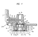
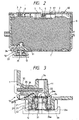
- FIGS. 1 and 2 show an ink cartridge constructed in accordance with a preferred embodiment of the present invention.
- the ink cartridge of this embodiment is especially designed for monochromatic printers.
- an ink cartridge main body indicated generally as 1
- Ink cartridge main body 1 is made of a resin material that suppresses evaporation of ink and is constructed to allow air passage.
- ink cartridge main body 1 The upper opening of ink cartridge main body 1 is covered integrally with a cover 2 having both an ink charging port 3 sealed by a spherical stopper 4 and an air vent 5 similarly sealed by a spherical stopper 6 designed to permit air flow into the ink cartridge while preventing ink loss.
- the air vent 5 communicates with atomosphere through a winding groove 61 and an air communication hole 60.
- An ink supply port is formed on one side of the bottom of ink cartridge main body 1.
- Ink supply port 10 communicates with an ink supply needle 31 of a recording head (not shown).
- an ink absorbing member 8 formed of a flexible porous material, is disposed within main body 1.
- a biasing plate 7 is positioned with respect to cover 2 to form a gap between cover 2 and ink absorbing member 8.
- the ink supply needle is positioned relative to the ink cartridge by a positioning member 33 which is dimensioned to receive an outwardly projecting portion 12 of the ink receiving and transmitting portion of the ink cartridge which defines the ink supply port.
- Ink supply port 10 includes an inward projecting portion 11 and an outward projecting portion 12.
- Inward projecting portion 11 projects inward into ink cartridge main body 1 to bias ink absorbing member 8.
- Outward projecting portion 12 projects outward from ink cartridge main body 1 to position ink cartridge main body 1.
- Inward projecting portion 11 is preferably provided such as to assist the flow of ink within ink absorbing member 8 to ink supply port 10 by compressing ink absorbing member 8 in the area adjacent inward projecting portion 11 to produce an average pore diameter of ink absorbing member 8 at this location smaller than the average pore diameter of absorbing body 8 at locations not adjacent inward projecting portion 11.
- a stepped insertion hole 14 in outward projecting portion 12 is dimensioned to receive a self-aligning ring 20 (described below).
- a through-hole 16 serving as an ink through-hole (part of the ink supply port) is provided in inward projecting portion 11. Stepped insertion hole 14 and through-hole 16 are formed coaxially so as to communicate with each other when ink cartridge main body 1 is coupled with in supply needle 31 of the recording head.
- Self-aligning ring 20 is made of a flexible resin material and comprises three distinct portions.
- a ring-like annular needle seal 21 (the first seal) having advantageously a circular form in section is coupled with a ring-like annular port seal 22 (the second seal) having advantageously a circular form in section by a thin truncated conical connecting ring 23 that is thinner than annular needle seal 21 or annular port seal 22 in the axial direction.
- the inner diameter of annular needle seal 21 is slightly smaller than the outer diameter of ink supply needle 31.
- the outer diameter of annular port seal 22 is slightly larger than the inner diameter of an entrance portion 14a of stepped insertion hole 14.
- a ring-like movable bush 24 having advantageously an L-shaped form in cross section is fitted adjacent annular needle seal 21 from outside so as to suppress the expansion of needle seal 21.
- the inner diameter of movable bush 24 is substantially smaller than the inner diameter of a portion 14b of stepped insertion hole 14.
- a ring-like fixed bush 25 having advantageously an L-shaped form in section is positioned within annular port seal 22 so as to insure fixed bush 25 remains in contact with the inner surface of entrance portion 14a of stepped insertion hole 14.
- Fixed bush 25 is dimensioned so that the inner end of fixed bush 25 does not come in contact with needle seal 21. Fixed bush 25 guides ink supply needle 31 into stepped insertion hole 14 during insertion.
- Fixed bush 25 is mounted in such a manner that movable bush 24 is in sliding contact with stepped portion 15 within stepped insertion hole 14 and that fixed bush 25 is fitted into entrance portion 14a of insertion hole 14.
- Projections 24a which preferably are radially extending projected bars 24a are formed on the inner end surface 9 of movable bush 24 and are maintained in sliding contact with stepped portion 15 within stepped insertion hole 14.
- ink cartridge main body 1 is evacuated to a negative pressure.
- a plurality of through-holes 24b are formed between projected bars 24a of movable bush 24 so that essentially all of the air within stepped insertion hole 14 can be released from around self-aligning ring 20 through through-holes 24b between the projected bars 24a.
- First seal member 9a in Fig. 2 which can be a sheet of seals the opening end of ink charging port 3, and second seal member 17 in FIG. 1 seals the opening end of ink supply port 10, and is penetrated by ink supply needle 31 during mounting of the ink supply cartridge.
- An electrode 35 extends through a bore 36 in a wall of ink cartridge body 1 and serves as one electrode of an ink exhaustion sensor to inform the user that the ink cartridge requires replacement.
- An O-ring 37 prevents escape of ink through bore 36.
- Ink cartridge main body 1 is coupled with the recording head in such a manner so as to align ink supply port 10 with ink supply needle 31.
- Ink supply needle 31 is inserted into ink supply port 10 while piercing seal member 17 that seals ink supply port 10.
- Ink supply needle 31 then enters into through-hole 16 and is hermetically fitted with movable bush 24.
- ribs 13 disposed around the circumference of the outward projecting portion 12 are fitted into annular positioning projected edge 33a of positioning member 33 disposed on the recording head to thereby fix ink cartridge main body 1 in position.
- Ink cartridge main body 1 is attached to the recording head so as to align ink supply needle 31 with positioning projected edge 33 even if ink supply needle 31 is not projected precisely coaxial with through-hole 16, or if ink supply needle 31 does not project precisely perpendicularly from the recording head.
- ink supply needle 31 is hermetically fitted to needle seal 21 even if not properly situated without greatly deforming needle seal 21. Needle seal 21 moves with movable bush 24 along stepped portion 15 within insertion hole 14 upon insertion of tapered tip portion 32 of ink supply needle 31, and thin conical connecting ring 23 is deformed and displaced in the radial direction outward.
- FIG. 3 depicts the positioning of the movable bush 24 and self-aligning ring 20 when an ink supply needle 31 is not aligned with the axis of insertion hole 14.
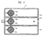
- FIGS. 4 and 5 depicts a mechanism for use with color or other multi-ink printers.
- a cartridge main body 41 has a plurality of ink tanks or compartments 42a, 42b, 42c fixed integrally thereto for containing separate inks, e.g., different color inks.
- Ink supply ports 50a, 50b, 50c having similar self-aligning rings 20a, 20b, 20c are disposed on the bottoms of ink tanks 42a, 42b, 42c.
- Each ink tank 42a, 42b and 42c has an air vent sealed by a stopper 6a, 6b and 6c respectively (FIG. 4).
- the ink changing ports of the three ink tanks or compartments are covered and sealed by sheet member 9'.
- self-aligning rings 20a, 20b, 20c inside the ink supply ports 50a, 50b, 50c are designed so that the misaligned ink supply needles displace the respective needle seals 21 and movable bushes 24 as described above so as to align each needle seal 21 with the position of the corresponding ink supply needle 31a, 31b, 31c while flexing each corresponding thin conical connecting ring 23.
- This construction thereby prevents the ink from leaking, and permits fitting and retaining each ink supply needle 31a, 31b, 31c hermetically with the corresponding needle seal 21 by only deforming the thin connecting members 23.
Landscapes
- Ink Jet (AREA)
Abstract
Description
- The present invention relates generally to an ink cartridge for use with an ink-jet type recording apparatus.
- Ink-jet type recording apparatuses use liquid ink to print recording data. Particularly, an ink-jet type recording apparatus employs an ink cartridge that supplies ink contained therein to the recording head. The ink cartridge is directly connected to the recording head through the use of an ink supply needle mounted on the recording head. Ink is delivered by utilizing a pressure difference between the ink in the recording head and the ink in the ink cartridge, and by capillary forces.
- As a result of this construction, the ink cartridge is required to have a structure for connecting the ink cartridge to the ink supply needle. This structure is disposed either on the lower surface of the ink cartridge or below the ink cartridge itself. This arrangement of the connecting structure in turn requires that an appropriate measure be taken to contain leakage of ink from the ink cartridge when the cartridge is connected to the ink supply needle. As has already been disclosed in Japanese Unexamined Patent Publication No. 50-74341, one method of dealing with the leaking of ink which is widely used is to employ a packing having a through-hole and a seal that allows the ink supply needle to be hermetically fitted into this through-hole at the ink supply port of the ink cartridge. With this structure, the ink cartridge can be positioned and retained in contact with the recording head without allowing any ink to leak by inserting the ink supply needle into the through-hole of the packing so as to pierce the seal.
- In order to prevent any ink from leaking, the ink supply port provided on the ink cartridge must have a minimal diameter. This design further requires a minimal diameter for the through-hole in the packing that is disposed in the ink supply port. However, if the ink supply needle is not positioned precisely coaxial with the through-hole in the packing disposed in the ink supply port, or if the ink supply needle is not perfectly perpendicular with respect to the packing disposed in the ink supply port, then the ink supply needle will not be centered upon insertion into the through-hole of the packing. As a result, the ink supply needle will be in contact with only a portion of the packing, whereas the remaining portion of the packing will not come in contact with the ink supply needle. Thus, ink will leak from between the ink supply needle and the packing where the ink supply needle does not contact the packing.
- This problem of leaking ink also arises from inconsistent positioning tolerances among the multiple ink supply needles in a recording head for a color printer using more than one ink supply needle to supply color inks to a recording head from a plurality of color ink tanks. In many cases, the plurality of color ink tanks is provided as a plurality of compartments in a single tank, so that the spacing between the connecting structures of the ink tank compartment and between the respective ink supply needles is fixed, aggravating the tolerance problem.
- The present invention intends to overcome such difficulties and its object is to provide an improved ink tank or cartridge. This object is solved by the ink cartridge of
independent claim 2. Further advantaqeous features, aspects and details of the invention are evident from the dependent claims, the description and the drawings. The claims are intended to be understood as a first non-limiting approach of defining the invention in general terms. - Accordingly the present invention provides an ink tank with a seal which compensates for inconsistent positioning of ink-supply needles, or inconsistent inclines of ink-supply needles and keeps ink from leaking from the ink supply take while in use.
- The present invention, therefore, provides an ink cartridge for use with an ink-jet type recording apparatus which compensates for misalignment of the ink supply port and ink supply needle to stop any ink from leaking.
- Generally speaking, in accordance with a preferred aspect of the present invention, a novel ink cartridge is provided which is capable of compensating for any displacement of the ink supply needle with respect to the ink supply port at the time the ink supply needle is connected to the ink supply port. The needle and port can be connected without allowing the ink to leak.
The ink cartridge according to a further aspect of the present invention comprises at least one self-aligning ring operatively coupled to an ink supply port of the ink cartridge on the outlet or recording head side. In operation, each ink supply port is coupled with an ink supply needle emanating from the recording head through the self aligning ring. The self-aligning ring preferably includes: a first annular seal member whose inner diameter is slightly smaller than an outer diameter of the ink supply needle; a second annular seal member whose outer diameter is slightly larger than an inner diameter of the ink supply port; and a thin connecting member for connecting the two seal members. When coupled, even if the ink supply needle is not located precisely coaxial with the corresponding ink supply port, the ink supply needle can be connected to the ink supply port hermetically by flexing the thin connecting member, thereby eliminating any leakina of the ink. - Accordingly, it is an aspect of this invention to provide an improved ink transfer mechanism for transferring between an ink cartridge and a recording head.
- Another aspect of the invention is to provide an improved ink transfer mechanism capable of compensating for any misalignment of the ink supply needle with respect to the ink supply port during use.
- A further aspect of the invention is to provide an improved ink transfer mechanism wherein a self-aligning ring permits a hermetic seal between an ink cartridge and a recording head regardless of misalignment of the ink supply needle with respect to the ink supply port during use.
- The invention according to preferred enbodiments comprises the features of construction, combination of elements, and arrangement of parts, which will be exemplified in the construction hereinafter set forth.
- For a fuller understanding of the invention, reference is had to the following description taken in connection with the accompanying drawings, in which:
- FIG. 1 is a fragmentary enlarged cross-sectional view of an ink cartridge and recording head combination constructed in accordance with a preferred embodiment of the present invention;
- FIG. 2 is a cross-sectional view of the ink cartridge of FIG. 1 constructed in accordance with a preferred embodiment of the present invention shown mounted on an ink supply needle;
- FIG. 3 is a fragmentary enlarged cross-sectional view of the ink cartridge and recording combination of FIG. 1 illustrating the operation of the invention where the ink supply needle is not properly aligned.
- FIG. 4 is an exploded perspective view of a multi compartment ink cartridge for color printing and associated recording head combination constructed in accordance with a second embodiment of the present invention; and
- FIG. 5 is a bottom plan view of the ink cartridge of FIG. 4 constructed in accordance with the second embodiment of the present invention.
- FIGS. 1 and 2 show an ink cartridge constructed in accordance with a preferred embodiment of the present invention. The ink cartridge of this embodiment is especially designed for monochromatic printers. Referring to FIG. 2, an ink cartridge main body, indicated generally as 1, is integrally formed into a box having an opening on top. Ink cartridge
main body 1 is made of a resin material that suppresses evaporation of ink and is constructed to allow air passage. - The upper opening of ink cartridge
main body 1 is covered integrally with acover 2 having both anink charging port 3 sealed by a spherical stopper 4 and anair vent 5 similarly sealed by a spherical stopper 6 designed to permit air flow into the ink cartridge while preventing ink loss. Theair vent 5 communicates with atomosphere through awinding groove 61 and anair communication hole 60. - An ink supply port, indicated generally as 10, is formed on one side of the bottom of ink cartridge
main body 1.Ink supply port 10 communicates with anink supply needle 31 of a recording head (not shown). Further, anink absorbing member 8, formed of a flexible porous material, is disposed withinmain body 1. Abiasing plate 7 is positioned with respect to cover 2 to form a gap betweencover 2 and ink absorbingmember 8. The ink supply needle is positioned relative to the ink cartridge by apositioning member 33 which is dimensioned to receive an outwardly projectingportion 12 of the ink receiving and transmitting portion of the ink cartridge which defines the ink supply port. - Reference is now made to FIG. 1, wherein
ink supply port 10 is shown in enlarged form.Ink supply port 10 includes aninward projecting portion 11 and an outwardprojecting portion 12. Inward projectingportion 11 projects inward into ink cartridgemain body 1 to bias ink absorbingmember 8. Outward projectingportion 12 projects outward from ink cartridgemain body 1 to position ink cartridgemain body 1. Inward projectingportion 11 is preferably provided such as to assist the flow of ink withinink absorbing member 8 toink supply port 10 by compressingink absorbing member 8 in the area adjacent inward projectingportion 11 to produce an average pore diameter ofink absorbing member 8 at this location smaller than the average pore diameter of absorbingbody 8 at locations not adjacent inward projectingportion 11. This reduction in the average pore diameter in the vicinity of inward projectingportion 11 increases the capillary force, assisting the ink flow toink supply port 10.Mesh filter 34 is positioned at the end of inwardly projectingportion 11 to assist in preventing particles and air bubbles from entering the ink supply port. Outward projectingportion 12 positions ink cartridgemain body 1 by engaging a plurality ofribs 13 arranged on the circumferential surface of ink cartridgemain body 1 with an annular positioning projectededge 33 disposed on the back of the recording head and also aids in connectingink supply port 10 toink supply needle 31. - A
stepped insertion hole 14 in outward projectingportion 12 is dimensioned to receive a self-aligning ring 20 (described below). In addition, a through-hole 16 serving as an ink through-hole (part of the ink supply port) is provided in inward projectingportion 11. Steppedinsertion hole 14 and through-hole 16 are formed coaxially so as to communicate with each other when ink cartridgemain body 1 is coupled with insupply needle 31 of the recording head. - Self-aligning
ring 20 will now be described with reference to FIG. 1. Self-aligningring 20 is made of a flexible resin material and comprises three distinct portions. A ring-like annular needle seal 21 (the first seal) having advantageously a circular form in section is coupled with a ring-like annular port seal 22 (the second seal) having advantageously a circular form in section by a thin truncated conical connectingring 23 that is thinner thanannular needle seal 21 orannular port seal 22 in the axial direction. The inner diameter ofannular needle seal 21 is slightly smaller than the outer diameter ofink supply needle 31. The outer diameter ofannular port seal 22 is slightly larger than the inner diameter of anentrance portion 14a of steppedinsertion hole 14. - A ring-like
movable bush 24 having advantageously an L-shaped form in cross section is fitted adjacentannular needle seal 21 from outside so as to suppress the expansion ofneedle seal 21. The inner diameter ofmovable bush 24 is substantially smaller than the inner diameter of aportion 14b of steppedinsertion hole 14. In addition, a ring-likefixed bush 25 having advantageously an L-shaped form in section is positioned withinannular port seal 22 so as to insure fixedbush 25 remains in contact with the inner surface ofentrance portion 14a of steppedinsertion hole 14.Fixed bush 25 is dimensioned so that the inner end of fixedbush 25 does not come in contact withneedle seal 21.Fixed bush 25 guidesink supply needle 31 into steppedinsertion hole 14 during insertion.Fixed bush 25 is mounted in such a manner thatmovable bush 24 is in sliding contact with steppedportion 15 within steppedinsertion hole 14 and that fixedbush 25 is fitted intoentrance portion 14a ofinsertion hole 14.Projections 24a which preferably are radially extending projectedbars 24a are formed on the inner end surface 9 ofmovable bush 24 and are maintained in sliding contact with steppedportion 15 within steppedinsertion hole 14. When ink is injected into ink cartridgemain body 1, ink cartridgemain body 1 is evacuated to a negative pressure. A plurality of through-holes 24b are formed between projectedbars 24a ofmovable bush 24 so that essentially all of the air within steppedinsertion hole 14 can be released from around self-aligningring 20 through through-holes 24b between the projectedbars 24a. Additional throughholes 25a are formed in fixedbush 25 for the same purpose. The releasing of the air in this manner prevents the ink charging pressure from causing self-aligningring 20 from being detached frominsertion hole 14. In effect, during injection of the ink intoink cartridge body 1 under negative pressure, ink essentially occupies the portion ofinsertion hole 14 not occupied by self-aligningring 20,movable bush 24, and fixedbush 25. - First seal member 9a in Fig. 2 which can be a sheet of seals the opening end of
ink charging port 3, andsecond seal member 17 in FIG. 1 seals the opening end ofink supply port 10, and is penetrated byink supply needle 31 during mounting of the ink supply cartridge. - An
electrode 35 extends through abore 36 in a wall ofink cartridge body 1 and serves as one electrode of an ink exhaustion sensor to inform the user that the ink cartridge requires replacement. An O-ring 37 prevents escape of ink throughbore 36. - The procedure for attaching ink cartridge
main body 1 to a recording head will now be described. Ink cartridgemain body 1 is coupled with the recording head in such a manner so as to alignink supply port 10 withink supply needle 31.Ink supply needle 31 is inserted intoink supply port 10 while piercingseal member 17 that sealsink supply port 10.Ink supply needle 31 then enters into through-hole 16 and is hermetically fitted withmovable bush 24. Simultaneously therewith,ribs 13 disposed around the circumference of the outward projectingportion 12 are fitted into annular positioning projectededge 33a of positioningmember 33 disposed on the recording head to thereby fix ink cartridgemain body 1 in position. Ink cartridgemain body 1 is attached to the recording head so as to alignink supply needle 31 with positioning projectededge 33 even ifink supply needle 31 is not projected precisely coaxial with through-hole 16, or ifink supply needle 31 does not project precisely perpendicularly from the recording head. As shown in FIG. 3,ink supply needle 31 is hermetically fitted toneedle seal 21 even if not properly situated without greatly deformingneedle seal 21.Needle seal 21 moves withmovable bush 24 along steppedportion 15 withininsertion hole 14 upon insertion of taperedtip portion 32 ofink supply needle 31, and thinconical connecting ring 23 is deformed and displaced in the radial direction outward. Thus,ink supply needle 31 is correctly fitted regardless of the precise position or angle ofink supply needle 31. Reference is now made to FIG. 3 which depicts the positioning of themovable bush 24 and self-aligningring 20 when anink supply needle 31 is not aligned with the axis ofinsertion hole 14. - Reference is now made to FIGS. 4 and 5 wherein a second embodiment of the present invention is shown, like elements being given like reference numerals. This second embodiment depicts a mechanism for use with color or other multi-ink printers. A cartridge
main body 41 has a plurality of ink tanks orcompartments 42a, 42b, 42c fixed integrally thereto for containing separate inks, e.g., different color inks.Ink supply ports rings ink tanks 42a, 42b, 42c. Eachink tank 42a, 42b and 42c has an air vent sealed by astopper - In the situation where
ink cartridge 41 is attached to a recording head having inconsistent positioning tolerances amongink supply needles rings ink supply ports movable bushes 24 as described above so as to align eachneedle seal 21 with the position of the correspondingink supply needle conical connecting ring 23. This construction thereby prevents the ink from leaking, and permits fitting and retaining eachink supply needle needle seal 21 by only deforming the thin connectingmembers 23. - It will thus be seen that the objects set forth above, among those made apparent from the preceding description, are efficiently attained and, since certain changes may be made in carrying out the above method without departing from the spirit and scope of the invention, it is intended that all matter contained in the above description shall be interpreted as illustrative and not in a limiting sense.
Claims (13)
- An ink cartridge for mounting on at least one ink supply needle (31, 31a, 31b, 31c) of a recording head, comprising:
at least one ink cartridge main body (1, 41)
an ink supply port (10, 50a, 50b, 50c) disposed in a wall of said ink cartridge main body (1, 41) and communicating from the interior to the exterior of said ink cartridge for the flow of ink therethrough, and
a self-aligning ring (20, 20a, 20b, 20c) mounted within said ink supply port (10, 50a, 50b, 50c) and having an interior facing side and an exterior facing side, said self-aligning ring further comprising:
a first annular seal member (21) on the interior facing side of said self-aligning ring (20, 20a, 20b, 20c) and having an inner diameter less than the outer diameter of said ink supply needle (31, 31a, 31b, 31c),
a second annular seal member (22) on the exterior facing side of said self-aligning ring (20, 20a, 20b, 20c) and having an outer diameter greater than the inner diameter of the adjacent region of said ink supply port (10, 50a, 50b, 50c) and
a flexible connecting member (23) coupling said first annular seal member (21) and said second annular seal member (22) to permit essentially lateral displacement of said first annular seal member (21) relative to said second annular seal member (22) in said ink supply port (10, 50a, 50b, 50c). - The ink cartridge especially of claim 1, for mounting on a recording head having at least two ink supply needles (31a, 31b, 31c) comprising:
at least two ink cartridge main bodies joined as a unit (41) each ink cartridge main body having an exterior wall,
an ink supply port (50a, 50b, 50c) in said exterior wall of each of said ink cartridge main bodies so as to be in essential registration with one of said ink supply needles (31a, 31b, 31c), said ink supply port communicating from the interior to the exterior of its respective ink cartridge main bodies for the flow of ink therethrough, and
a self-aligning ring (20a, 20b , 20c) mounted within each said ink supply port (50a, 50b, 50c) and having an interior facing side and an exterior facing side, each of said self-aligning rings further comprising:
a first annular seal member (21) on the interior facing side of said self-aligning ring (20a, 20b, 20c) and having an inner diameter less than the outer diameter of the associated ink supply needle (31a, 31b, 31c);
a second annular seal member (22) on the exterior facing side of said self-aligning ring (20a, 20b, 20c) and having an outer diameter greater than the inner diameter of the adjacent region of the associated ink supply port (50a, 50b , 50c); and
a flexible connecting member (23) coupling said first annular seal member (21) and said second annular seal member (22) to permit essentially lateral displacement of said first annular seal member (21) relative to said second annular seal member (22) in the associated ink supply port (50a, 50b, 50c). - The ink cartridge of any one of the preceding claims, wherein said ink cartridge main body (1, 41) has a plurality of walls.
- The ink cartridge of any one of the preceding claims, further including an annular movable bush (24) having an inner diameter smaller than the outer diameter of said first annular seal member (21) and an outer diameter smaller than the inner diameter of the adjacent region of said ink supply port to limit the expansion of said first annular seal member (21) when the bush (24) is disposed on the outer circumference of said respective first annular seal member (21).
- The ink cartridge of claim 4, wherein said annular movable bush (24) has an essentially L-shape in cross section, a first arm of said L being engaged by said outer circumference of said first annular seal member (21), a second arm of said L being engaged on the interior side of said first annular seal member.
- The ink cartridge of any one of the preceding claims, wherein said respective ink supply port (10, 50a, 50b, 50c) is formed with a stepped interior construction defining a region of greater diameter for receiving said self aligning ring (20, 20a, 20b, 20c) with the interior side of the second arm of the movable bush (24) facing and engaging said interior step of said ink supply port.
- The ink cartridge of claim 6, wherein said interior side of said second arm of said movable bush (24) is formed with spaced projections (24a) extending toward and engaging said step.
- The ink cartridge of claim 7 wherein the projections (24a) are radially extending spaced projections.
- The ink cartridge of any one of claims 4 to 8, wherein said second arm of said movable bush (24) is formed with at least one through hole providing communication between the interior and exterior of said movable bush.
- The ink cartridge of claim 9, wherein said through hole is in a region between said projections.
- The ink cartridge of any one of the preceding claims, further including an annular fixed bush (25) for guiding said respective ink supply needle (31, 31a, 31b, 31c) disposed along the inner circumference of said second annular seal member (22) to engage said second annular seal member against the inner circumference of the adjacent region of said associated ink supply port (10, 50a, 50b, 50c).
- The ink cartridge of claim 10 or 11, wherein each of said annular fixed bush (25) has essentially an L-shape in cross-section, a first arm of said L being engaged by said inner circumference of said second annular seal member (22) and a second arm of said L being engaged by the exterior side of said second annular seal member (22).
- The ink cartridge of claim 10 to 12, wherein said second arm of said respective fixed bush is formed with at least one through hole (25a) providing communication between the interior and exterior of said fixed bush.
Priority Applications (1)
| Application Number | Priority Date | Filing Date | Title |
|---|---|---|---|
| EP99103201A EP0914956B1 (en) | 1993-11-05 | 1994-11-04 | Ink cartridge for printer |
Applications Claiming Priority (3)
| Application Number | Priority Date | Filing Date | Title |
|---|---|---|---|
| JP30115193 | 1993-11-05 | ||
| JP30115193A JP3199092B2 (en) | 1993-11-05 | 1993-11-05 | Ink cartridge for printer |
| JP301151/93 | 1993-11-05 |
Related Child Applications (1)
| Application Number | Title | Priority Date | Filing Date |
|---|---|---|---|
| EP99103201A Division EP0914956B1 (en) | 1993-11-05 | 1994-11-04 | Ink cartridge for printer |
Publications (3)
| Publication Number | Publication Date |
|---|---|
| EP0665108A2 true EP0665108A2 (en) | 1995-08-02 |
| EP0665108A3 EP0665108A3 (en) | 1996-07-24 |
| EP0665108B1 EP0665108B1 (en) | 1999-09-15 |
Family
ID=17893400
Family Applications (2)
| Application Number | Title | Priority Date | Filing Date |
|---|---|---|---|
| EP99103201A Expired - Lifetime EP0914956B1 (en) | 1993-11-05 | 1994-11-04 | Ink cartridge for printer |
| EP94117447A Expired - Lifetime EP0665108B1 (en) | 1993-11-05 | 1994-11-04 | Ink cartridge for printer |
Family Applications Before (1)
| Application Number | Title | Priority Date | Filing Date |
|---|---|---|---|
| EP99103201A Expired - Lifetime EP0914956B1 (en) | 1993-11-05 | 1994-11-04 | Ink cartridge for printer |
Country Status (6)
| Country | Link |
|---|---|
| US (2) | US5633667A (en) |
| EP (2) | EP0914956B1 (en) |
| JP (1) | JP3199092B2 (en) |
| DE (2) | DE69432157T2 (en) |
| HK (1) | HK1020550A1 (en) |
| SG (1) | SG52541A1 (en) |
Cited By (15)
| Publication number | Priority date | Publication date | Assignee | Title |
|---|---|---|---|---|
| EP0703083A3 (en) * | 1994-09-16 | 1996-08-07 | Seiko Epson Corp | Ink cartridge for ink jet printer and method of charging ink into said cartridge |
| FR2751916A1 (en) * | 1996-08-02 | 1998-02-06 | Seiko Epson Corp | INK CARTRIDGE AND PRINTING APPARATUS |
| EP0829363A2 (en) * | 1996-08-30 | 1998-03-18 | Canon Kabushiki Kaisha | Ink container, ink container holder for removably holding ink container, and ink container cap |
| GB2306401B (en) * | 1994-09-16 | 1998-05-06 | Seiko Epson Corp | Ink tank cartridge for a printer or the like |
| US5751322A (en) * | 1996-02-13 | 1998-05-12 | Hewlett-Packard Company | Limited access needle/septum ink-supply interface mechanism |
| FR2760405A1 (en) * | 1997-03-07 | 1998-09-11 | Seiko Epson Corp | INK CARTRIDGE FOR INK JET PRINTER |
| EP0864428A2 (en) * | 1997-03-12 | 1998-09-16 | Seiko Epson Corporation | Ink cartridge for ink jet recorder and method of manufacturing same |
| GB2323564A (en) * | 1995-05-17 | 1998-09-30 | Dynamic Cassette Int | Integral first and second seal arrangement for an ink supply port of an ink cartridge |
| EP0949080A3 (en) * | 1998-04-06 | 2000-01-26 | Xerox Corporation | Ink container with improved sealing of ink container outlet port |
| US6019465A (en) * | 1995-04-05 | 2000-02-01 | Seiko Epson Corporation | Ink-jet recording apparatus |
| EP0976564A2 (en) * | 1998-07-31 | 2000-02-02 | Hewlett-Packard Company | Sealing member for a fluid container |
| GB2342619A (en) * | 1996-08-02 | 2000-04-19 | Seiko Epson Corp | Ink cartridge supply port with elastic sealing member having a tapered surface and a ring-like part to guide and secure a supply needle when mounted thereon |
| US6145974A (en) * | 1983-10-13 | 2000-11-14 | Seiko Epson Corporation | Ink-supplied printer head and ink container |
| EP1524118A1 (en) * | 2003-10-14 | 2005-04-20 | Print-rite. Unicorn Image Products Co., Ltd. of Zhuhai | Attachable and detachable ink container for continuous ink jet printer |
| US6951389B2 (en) | 1996-02-21 | 2005-10-04 | Seiko Epson Corporation | Ink cartridge |
Families Citing this family (42)
| Publication number | Priority date | Publication date | Assignee | Title |
|---|---|---|---|---|
| US6474798B1 (en) | 1984-10-11 | 2002-11-05 | Seiko Epson Corporation | Ink supplied printer head and ink container |
| US6238042B1 (en) * | 1994-09-16 | 2001-05-29 | Seiko Epson Corporation | Ink cartridge for ink jet printer and method of charging ink into said cartridge |
| US5917525A (en) * | 1995-10-30 | 1999-06-29 | Pelikan Produktions Ag | Ink cartridge for a print head of an ink-jet printer |
| GB2315045B (en) * | 1996-07-05 | 1998-11-25 | Seiko Epson Corp | Ink cartridge and loading mechanism for the ink cartridge |
| JPH10193646A (en) * | 1997-01-09 | 1998-07-28 | Seiko Epson Corp | Print head unit, ink jet printer having the same, and ink cartridge |
| US6786420B1 (en) | 1997-07-15 | 2004-09-07 | Silverbrook Research Pty. Ltd. | Data distribution mechanism in the form of ink dots on cards |
| US6618117B2 (en) | 1997-07-12 | 2003-09-09 | Silverbrook Research Pty Ltd | Image sensing apparatus including a microcontroller |
| US7110024B1 (en) | 1997-07-15 | 2006-09-19 | Silverbrook Research Pty Ltd | Digital camera system having motion deblurring means |
| US6624848B1 (en) | 1997-07-15 | 2003-09-23 | Silverbrook Research Pty Ltd | Cascading image modification using multiple digital cameras incorporating image processing |
| US20040119829A1 (en) | 1997-07-15 | 2004-06-24 | Silverbrook Research Pty Ltd | Printhead assembly for a print on demand digital camera system |
| US6879341B1 (en) | 1997-07-15 | 2005-04-12 | Silverbrook Research Pty Ltd | Digital camera system containing a VLIW vector processor |
| US6690419B1 (en) | 1997-07-15 | 2004-02-10 | Silverbrook Research Pty Ltd | Utilising eye detection methods for image processing in a digital image camera |
| US6508546B2 (en) * | 1998-10-16 | 2003-01-21 | Silverbrook Research Pty Ltd | Ink supply arrangement for a portable ink jet printer |
| US6733116B1 (en) * | 1998-10-16 | 2004-05-11 | Silverbrook Research Pty Ltd | Ink jet printer with print roll and printhead assemblies |
| AUPP702098A0 (en) * | 1998-11-09 | 1998-12-03 | Silverbrook Research Pty Ltd | Image creation method and apparatus (ART73) |
| AUPP702198A0 (en) * | 1998-11-09 | 1998-12-03 | Silverbrook Research Pty Ltd | Image creation method and apparatus (ART79) |
| AUPP701798A0 (en) * | 1998-11-09 | 1998-12-03 | Silverbrook Research Pty Ltd | Image creation method and apparatus (ART75) |
| CA2430629C (en) | 1998-11-11 | 2007-01-02 | Seiko Epson Corporation | Ink-jet printing apparatus and ink cartridge |
| AUPQ056099A0 (en) | 1999-05-25 | 1999-06-17 | Silverbrook Research Pty Ltd | A method and apparatus (pprint01) |
| JP3755344B2 (en) * | 1999-07-07 | 2006-03-15 | セイコーエプソン株式会社 | PRINT HEAD DEVICE AND INK JET PRINTER HAVING THE SAME |
| PT1095777E (en) * | 1999-10-29 | 2006-06-30 | Seiko Epson Corp | INK CARTRIDGE FOR USE IN A INK JET GRAPHICS DEVICE |
| GB9925988D0 (en) * | 1999-11-03 | 2000-01-12 | Dynamic Cassette Int | An ink cartridge |
| JP4592174B2 (en) * | 1999-11-15 | 2010-12-01 | オセ−テクノロジーズ ビーブイ | Ink jet apparatus having ink pellet dispenser |
| US6332676B1 (en) | 2000-01-05 | 2001-12-25 | Hewlett-Packard Company | Vent for an ink-jet print cartridge |
| US6935730B2 (en) * | 2000-04-03 | 2005-08-30 | Unicorn Image Products Co. Ltd. Of Zhuhai | One-way valve, valve unit assembly, and ink cartridge using the same |
| US20030107626A1 (en) * | 2000-08-16 | 2003-06-12 | Xiao Qingguo | Ink cartridge having bellows valve, ink filling method and apparatus used thereof |
| JP2002079690A (en) * | 2000-06-30 | 2002-03-19 | Seiko Epson Corp | Cartridge for maintenance and ink jet recorder using the cartridge |
| US20050243147A1 (en) * | 2000-10-12 | 2005-11-03 | Unicorn Image Products Co. Ltd. | Ink cartridge having bellows valve, ink filling method and apparatus used thereof |
| DE10100171B4 (en) * | 2001-01-04 | 2005-02-24 | Artech Gmbh Design + Production In Plastic | Pierceable closure element and ink container with pierceable closure element |
| US6929356B2 (en) * | 2001-03-21 | 2005-08-16 | Canon Kabushiki Kaisha | Container of consumable supplies for a printer and printer utilizing the container |
| JP4193435B2 (en) * | 2002-07-23 | 2008-12-10 | ブラザー工業株式会社 | Ink cartridge and ink filling method thereof |
| US6386691B1 (en) * | 2001-06-05 | 2002-05-14 | Win-Yin Liu | Ink cartridge of a printer facilitating second refilling |
| US7431427B2 (en) * | 2002-06-13 | 2008-10-07 | Silverbrook Research Pty Ltd | Ink supply arrangement with improved ink flows |
| EP1545885B1 (en) | 2002-08-22 | 2010-11-17 | MVM Technologies, Inc. | Universal inkjet printer device |
| AU2003901513A0 (en) * | 2003-03-28 | 2003-04-17 | Proteome Systems Intellectual Property Pty Ltd | Apparatus for dispensing and printing fluids |
| DE50304298D1 (en) * | 2003-11-19 | 2006-08-31 | 3T Supplies Ag | Ink cartridge, ink cartridge unit and inkjet printhead |
| JP4513337B2 (en) | 2004-01-23 | 2010-07-28 | セイコーエプソン株式会社 | ink cartridge |
| US7591400B2 (en) * | 2005-02-28 | 2009-09-22 | Cristian Penciu | Cartridge for dispenser of particular fluid substances |
| JP2006248159A (en) | 2005-03-14 | 2006-09-21 | Seiko Epson Corp | Ink cartridge and method of producing the same |
| JP4737430B2 (en) * | 2006-06-22 | 2011-08-03 | セイコーエプソン株式会社 | Carriage device, recording device, liquid ejecting device |
| US9738079B2 (en) * | 2013-11-29 | 2017-08-22 | Hitachi Industrial Equipment Systems Co., Ltd. | Replenishment container and inkjet recording device comprising same |
| CN113601989B (en) * | 2021-07-27 | 2024-01-19 | 珠海天威飞马打印耗材有限公司 | Inking device and inking method thereof |
Citations (8)
| Publication number | Priority date | Publication date | Assignee | Title |
|---|---|---|---|---|
| DE2709730A1 (en) * | 1977-03-05 | 1978-09-07 | Olympia Werke Ag | Ink jet printer refill container - has plastics bag esp. of polyethylene, attached by adhesive permanently to silicone rubber stopper located in container opening |
| GB2003793A (en) * | 1977-09-06 | 1979-03-21 | Bell & Howell Co | Ink jet printer ink cartridge |
| DE2916472A1 (en) * | 1979-04-24 | 1980-11-06 | Olympia Werke Ag | Printer ink container with ink sack heater - expelling residual gas and making available residual ink |
| US4447820A (en) * | 1981-06-08 | 1984-05-08 | Canon Kabushiki Kaisha | Ink supplying mechanism |
| US4591875A (en) * | 1985-04-12 | 1986-05-27 | Eastman Kodak Company | Ink cartridge and cooperative continuous ink jet printing apparatus |
| JPS63162249A (en) * | 1986-12-26 | 1988-07-05 | Ricoh Co Ltd | Ink cartridge device of ink jet printer |
| JPS63276554A (en) * | 1987-05-08 | 1988-11-14 | Ricoh Co Ltd | Ink cartridge apparatus |
| EP0633138A2 (en) * | 1993-07-06 | 1995-01-11 | Brother Kogyo Kabushiki Kaisha | Ink supply device |
Family Cites Families (7)
| Publication number | Priority date | Publication date | Assignee | Title |
|---|---|---|---|---|
| US4162501A (en) * | 1977-08-08 | 1979-07-24 | Silonics, Inc. | Ink supply system for an ink jet printer |
| US4771295B1 (en) * | 1986-07-01 | 1995-08-01 | Hewlett Packard Co | Thermal ink jet pen body construction having improved ink storage and feed capability |
| US4806032A (en) * | 1987-05-11 | 1989-02-21 | Hewlett-Packard Company | Conical vent containing capillary bore |
| DE69031872T2 (en) * | 1989-09-18 | 1998-04-30 | Canon Kk | Method of filling an ink cartridge for ink jet recorders |
| JPH03169563A (en) * | 1989-11-29 | 1991-07-23 | Mitsubishi Pencil Co Ltd | Ink jet cartridge |
| EP0480302B1 (en) * | 1990-10-03 | 1996-05-01 | Canon Kabushiki Kaisha | Ink jet recording apparatus |
| US5477963A (en) * | 1992-01-28 | 1995-12-26 | Seiko Epson Corporation | Ink-jet recording apparatus and ink tank cartridge therefor |
-
1993
- 1993-11-05 JP JP30115193A patent/JP3199092B2/en not_active Expired - Fee Related
-
1994
- 1994-11-04 DE DE69432157T patent/DE69432157T2/en not_active Expired - Fee Related
- 1994-11-04 EP EP99103201A patent/EP0914956B1/en not_active Expired - Lifetime
- 1994-11-04 SG SG1996005769A patent/SG52541A1/en unknown
- 1994-11-04 DE DE69420696T patent/DE69420696T2/en not_active Expired - Fee Related
- 1994-11-04 US US08/334,719 patent/US5633667A/en not_active Expired - Fee Related
- 1994-11-04 EP EP94117447A patent/EP0665108B1/en not_active Expired - Lifetime
-
1997
- 1997-05-21 US US08/861,253 patent/US5907341A/en not_active Expired - Fee Related
-
1999
- 1999-11-09 HK HK99105139A patent/HK1020550A1/en not_active IP Right Cessation
Patent Citations (8)
| Publication number | Priority date | Publication date | Assignee | Title |
|---|---|---|---|---|
| DE2709730A1 (en) * | 1977-03-05 | 1978-09-07 | Olympia Werke Ag | Ink jet printer refill container - has plastics bag esp. of polyethylene, attached by adhesive permanently to silicone rubber stopper located in container opening |
| GB2003793A (en) * | 1977-09-06 | 1979-03-21 | Bell & Howell Co | Ink jet printer ink cartridge |
| DE2916472A1 (en) * | 1979-04-24 | 1980-11-06 | Olympia Werke Ag | Printer ink container with ink sack heater - expelling residual gas and making available residual ink |
| US4447820A (en) * | 1981-06-08 | 1984-05-08 | Canon Kabushiki Kaisha | Ink supplying mechanism |
| US4591875A (en) * | 1985-04-12 | 1986-05-27 | Eastman Kodak Company | Ink cartridge and cooperative continuous ink jet printing apparatus |
| JPS63162249A (en) * | 1986-12-26 | 1988-07-05 | Ricoh Co Ltd | Ink cartridge device of ink jet printer |
| JPS63276554A (en) * | 1987-05-08 | 1988-11-14 | Ricoh Co Ltd | Ink cartridge apparatus |
| EP0633138A2 (en) * | 1993-07-06 | 1995-01-11 | Brother Kogyo Kabushiki Kaisha | Ink supply device |
Non-Patent Citations (2)
| Title |
|---|
| PATENT ABSTRACTS OF JAPAN vol. 12, no. 428 (M-762) [3275] , 11 November 1988 & JP-A-63 162249 (RICOH), 5 July 1988, * |
| PATENT ABSTRACTS OF JAPAN vol. 13, no. 77 (M-801) [3425] , 22 February 1989 & JP-A-63 276554 (RICOH), 14 November 1988, * |
Cited By (32)
| Publication number | Priority date | Publication date | Assignee | Title |
|---|---|---|---|---|
| US6145974A (en) * | 1983-10-13 | 2000-11-14 | Seiko Epson Corporation | Ink-supplied printer head and ink container |
| GB2306401B (en) * | 1994-09-16 | 1998-05-06 | Seiko Epson Corp | Ink tank cartridge for a printer or the like |
| EP0703083A3 (en) * | 1994-09-16 | 1996-08-07 | Seiko Epson Corp | Ink cartridge for ink jet printer and method of charging ink into said cartridge |
| US6814435B1 (en) | 1995-04-05 | 2004-11-09 | Seiko Epson Corporation | Ink-jet recording apparatus |
| US6019465A (en) * | 1995-04-05 | 2000-02-01 | Seiko Epson Corporation | Ink-jet recording apparatus |
| GB2323564A (en) * | 1995-05-17 | 1998-09-30 | Dynamic Cassette Int | Integral first and second seal arrangement for an ink supply port of an ink cartridge |
| GB2323564B (en) * | 1995-05-17 | 1999-02-24 | Dynamic Cassette Int | An ink cartridge for an ink jet printer |
| US5751322A (en) * | 1996-02-13 | 1998-05-12 | Hewlett-Packard Company | Limited access needle/septum ink-supply interface mechanism |
| US6951389B2 (en) | 1996-02-21 | 2005-10-04 | Seiko Epson Corporation | Ink cartridge |
| GB2342619A (en) * | 1996-08-02 | 2000-04-19 | Seiko Epson Corp | Ink cartridge supply port with elastic sealing member having a tapered surface and a ring-like part to guide and secure a supply needle when mounted thereon |
| US6474799B1 (en) | 1996-08-02 | 2002-11-05 | Seiko Epson Corporation | Ink cartridge and a printing device using the ink cartridge |
| FR2751916A1 (en) * | 1996-08-02 | 1998-02-06 | Seiko Epson Corp | INK CARTRIDGE AND PRINTING APPARATUS |
| GB2342619B (en) * | 1996-08-02 | 2000-08-30 | Seiko Epson Corp | Ink cartridge and a printing device using the ink cartridge |
| US6086193A (en) * | 1996-08-02 | 2000-07-11 | Seiko Epson Corporation | Ink cartridge and a printing device using the ink cartridge |
| EP0829363A3 (en) * | 1996-08-30 | 1999-01-27 | Canon Kabushiki Kaisha | Ink container, ink container holder for removably holding ink container, and ink container cap |
| US6102533A (en) * | 1996-08-30 | 2000-08-15 | Canon Kabushiki Kaisha | Ink container, ink container holder for removably holding ink container, and ink container cap |
| EP0829363A2 (en) * | 1996-08-30 | 1998-03-18 | Canon Kabushiki Kaisha | Ink container, ink container holder for removably holding ink container, and ink container cap |
| US6152555A (en) * | 1996-08-30 | 2000-11-28 | Canon Kabushiki Kaisha | Ink container, ink container holder for removably holding ink container, and ink container cap |
| FR2760405A1 (en) * | 1997-03-07 | 1998-09-11 | Seiko Epson Corp | INK CARTRIDGE FOR INK JET PRINTER |
| DE19809756B4 (en) * | 1997-03-07 | 2006-04-13 | Seiko Epson Corp. | Ink tank for an ink jet recording apparatus |
| US6170941B1 (en) | 1997-03-07 | 2001-01-09 | Seiko Epson Corporation | Ink cartridge for ink-jet recorder |
| FR2799689A1 (en) * | 1997-03-07 | 2001-04-20 | Seiko Epson Corp | INK CARTRIDGE FOR INK JET PRINTER |
| US6312115B1 (en) | 1997-03-12 | 2001-11-06 | Seiko Epson Corporation | Ink cartridge for ink jet recorder and method of manufacturing same |
| EP0864428A2 (en) * | 1997-03-12 | 1998-09-16 | Seiko Epson Corporation | Ink cartridge for ink jet recorder and method of manufacturing same |
| US6854834B2 (en) | 1997-03-12 | 2005-02-15 | Seiko Epson Corporation | Ink cartridge for ink-jet recorder and method of manufacturing same |
| US6929359B2 (en) | 1997-03-12 | 2005-08-16 | Seiko Epson Corporation | Ink cartridge for ink-jet recorder and method of manufacturing same |
| EP0864428A3 (en) * | 1997-03-12 | 1999-02-10 | Seiko Epson Corporation | Ink cartridge for ink jet recorder and method of manufacturing same |
| US7086723B2 (en) | 1997-03-12 | 2006-08-08 | Seiko Epson Corporation | Ink cartridge for ink-jet recorder and method of manufacturing same |
| EP0949080A3 (en) * | 1998-04-06 | 2000-01-26 | Xerox Corporation | Ink container with improved sealing of ink container outlet port |
| EP0976564A2 (en) * | 1998-07-31 | 2000-02-02 | Hewlett-Packard Company | Sealing member for a fluid container |
| EP0976564A3 (en) * | 1998-07-31 | 2001-05-02 | Hewlett-Packard Company, A Delaware Corporation | Sealing member for a fluid container |
| EP1524118A1 (en) * | 2003-10-14 | 2005-04-20 | Print-rite. Unicorn Image Products Co., Ltd. of Zhuhai | Attachable and detachable ink container for continuous ink jet printer |
Also Published As
| Publication number | Publication date |
|---|---|
| DE69432157T2 (en) | 2003-12-04 |
| DE69420696D1 (en) | 1999-10-21 |
| US5907341A (en) | 1999-05-25 |
| EP0914956A3 (en) | 1999-11-24 |
| US5633667A (en) | 1997-05-27 |
| JP3199092B2 (en) | 2001-08-13 |
| HK1020550A1 (en) | 2000-05-12 |
| DE69432157D1 (en) | 2003-03-27 |
| EP0665108A3 (en) | 1996-07-24 |
| EP0914956A2 (en) | 1999-05-12 |
| DE69420696T2 (en) | 2000-05-31 |
| EP0914956B1 (en) | 2003-02-19 |
| JPH07125238A (en) | 1995-05-16 |
| SG52541A1 (en) | 1998-09-28 |
| EP0665108B1 (en) | 1999-09-15 |
Similar Documents
| Publication | Publication Date | Title |
|---|---|---|
| EP0914956B1 (en) | Ink cartridge for printer | |
| EP1687147B1 (en) | Valve device, ink cartridge comprising the valve device and method of supplying ink | |
| EP1792737B9 (en) | Ink supply unit | |
| EP1013443B1 (en) | Ink cartridge for ink jet printer | |
| US6276788B1 (en) | Ink cartridge for an ink jet printer having quick disconnect valve 09 | |
| US5126767A (en) | Ink tank with dual-member sealing closure | |
| KR100466151B1 (en) | Electrical and fluidic interface for an ink supply | |
| CA2136791C (en) | Improved ink container, installing-removing method therefore, and apparatus usable with the same | |
| EP1839877B1 (en) | Ink cartridges and inkjet printer | |
| EP0778148B1 (en) | Keying system for ink supply containers | |
| KR20020012160A (en) | Ink cartridge for recording device and ink jet recording device | |
| US6280024B1 (en) | Ink cartridge for printer | |
| JPS634953A (en) | Ink supply apparatus | |
| EP1594704B1 (en) | Ink cartridge | |
| US6145967A (en) | Method and apparatus for configuring a fluid interconnect for an ink-jet printhead | |
| GB2315462A (en) | Ink cartridge having tapered bore | |
| EP1594703B1 (en) | Ink cartridge | |
| JPS639546A (en) | Ink-supplying part | |
| EP1086816A2 (en) | An ink cartridge | |
| JPS633958A (en) | Ink supply device | |
| US11787193B2 (en) | Liquid cartridge including first and second valves disposed in liquid supply portion, and system using the same | |
| JP2023144615A (en) | Cartridge, recording device, and method for manufacturing cartridge | |
| KR100445928B1 (en) | Ink supply container placement system and ink supply container manufacturing method |
Legal Events
| Date | Code | Title | Description |
|---|---|---|---|
| PUAI | Public reference made under article 153(3) epc to a published international application that has entered the european phase |
Free format text: ORIGINAL CODE: 0009012 |
|
| AK | Designated contracting states |
Kind code of ref document: A2 Designated state(s): CH DE FR GB IT LI NL SE |
|
| PUAL | Search report despatched |
Free format text: ORIGINAL CODE: 0009013 |
|
| AK | Designated contracting states |
Kind code of ref document: A3 Designated state(s): CH DE FR GB IT LI NL SE |
|
| 17P | Request for examination filed |
Effective date: 19961210 |
|
| 17Q | First examination report despatched |
Effective date: 19980212 |
|
| GRAG | Despatch of communication of intention to grant |
Free format text: ORIGINAL CODE: EPIDOS AGRA |
|
| GRAG | Despatch of communication of intention to grant |
Free format text: ORIGINAL CODE: EPIDOS AGRA |
|
| GRAG | Despatch of communication of intention to grant |
Free format text: ORIGINAL CODE: EPIDOS AGRA |
|
| GRAH | Despatch of communication of intention to grant a patent |
Free format text: ORIGINAL CODE: EPIDOS IGRA |
|
| GRAH | Despatch of communication of intention to grant a patent |
Free format text: ORIGINAL CODE: EPIDOS IGRA |
|
| GRAA | (expected) grant |
Free format text: ORIGINAL CODE: 0009210 |
|
| AK | Designated contracting states |
Kind code of ref document: B1 Designated state(s): CH DE FR GB IT LI NL SE |
|
| REG | Reference to a national code |
Ref country code: CH Ref legal event code: EP |
|
| ITF | It: translation for a ep patent filed | ||
| REF | Corresponds to: |
Ref document number: 69420696 Country of ref document: DE Date of ref document: 19991021 |
|
| ET | Fr: translation filed | ||
| REG | Reference to a national code |
Ref country code: CH Ref legal event code: NV Representative=s name: BOVARD AG PATENTANWAELTE |
|
| PLBE | No opposition filed within time limit |
Free format text: ORIGINAL CODE: 0009261 |
|
| STAA | Information on the status of an ep patent application or granted ep patent |
Free format text: STATUS: NO OPPOSITION FILED WITHIN TIME LIMIT |
|
| 26N | No opposition filed | ||
| REG | Reference to a national code |
Ref country code: GB Ref legal event code: IF02 |
|
| PGFP | Annual fee paid to national office [announced via postgrant information from national office to epo] |
Ref country code: NL Payment date: 20071115 Year of fee payment: 14 Ref country code: DE Payment date: 20071101 Year of fee payment: 14 |
|
| PGFP | Annual fee paid to national office [announced via postgrant information from national office to epo] |
Ref country code: CH Payment date: 20071029 Year of fee payment: 14 Ref country code: IT Payment date: 20071127 Year of fee payment: 14 |
|
| PGFP | Annual fee paid to national office [announced via postgrant information from national office to epo] |
Ref country code: SE Payment date: 20071106 Year of fee payment: 14 |
|
| PGFP | Annual fee paid to national office [announced via postgrant information from national office to epo] |
Ref country code: GB Payment date: 20071031 Year of fee payment: 14 Ref country code: FR Payment date: 20071108 Year of fee payment: 14 |
|
| REG | Reference to a national code |
Ref country code: CH Ref legal event code: PL |
|
| EUG | Se: european patent has lapsed | ||
| GBPC | Gb: european patent ceased through non-payment of renewal fee |
Effective date: 20081104 |
|
| PG25 | Lapsed in a contracting state [announced via postgrant information from national office to epo] |
Ref country code: NL Free format text: LAPSE BECAUSE OF NON-PAYMENT OF DUE FEES Effective date: 20090601 |
|
| NLV4 | Nl: lapsed or anulled due to non-payment of the annual fee |
Effective date: 20090601 |
|
| PG25 | Lapsed in a contracting state [announced via postgrant information from national office to epo] |
Ref country code: IT Free format text: LAPSE BECAUSE OF NON-PAYMENT OF DUE FEES Effective date: 20081104 |
|
| REG | Reference to a national code |
Ref country code: FR Ref legal event code: ST Effective date: 20090731 |
|
| PG25 | Lapsed in a contracting state [announced via postgrant information from national office to epo] |
Ref country code: LI Free format text: LAPSE BECAUSE OF NON-PAYMENT OF DUE FEES Effective date: 20081130 Ref country code: DE Free format text: LAPSE BECAUSE OF NON-PAYMENT OF DUE FEES Effective date: 20090603 Ref country code: CH Free format text: LAPSE BECAUSE OF NON-PAYMENT OF DUE FEES Effective date: 20081130 |
|
| PG25 | Lapsed in a contracting state [announced via postgrant information from national office to epo] |
Ref country code: GB Free format text: LAPSE BECAUSE OF NON-PAYMENT OF DUE FEES Effective date: 20081104 |
|
| PG25 | Lapsed in a contracting state [announced via postgrant information from national office to epo] |
Ref country code: SE Free format text: LAPSE BECAUSE OF NON-PAYMENT OF DUE FEES Effective date: 20081105 |
|
| PG25 | Lapsed in a contracting state [announced via postgrant information from national office to epo] |
Ref country code: FR Free format text: LAPSE BECAUSE OF NON-PAYMENT OF DUE FEES Effective date: 20081130 |