EP0664409B1 - Sliding contact bearing with integrated lip seal - Google Patents
Sliding contact bearing with integrated lip seal Download PDFInfo
- Publication number
- EP0664409B1 EP0664409B1 EP94120361A EP94120361A EP0664409B1 EP 0664409 B1 EP0664409 B1 EP 0664409B1 EP 94120361 A EP94120361 A EP 94120361A EP 94120361 A EP94120361 A EP 94120361A EP 0664409 B1 EP0664409 B1 EP 0664409B1
- Authority
- EP
- European Patent Office
- Prior art keywords
- sliding bearing
- bearing according
- support portion
- holding portion
- annular
- Prior art date
- Legal status (The legal status is an assumption and is not a legal conclusion. Google has not performed a legal analysis and makes no representation as to the accuracy of the status listed.)
- Expired - Lifetime
Links
Images
Classifications
-
- F—MECHANICAL ENGINEERING; LIGHTING; HEATING; WEAPONS; BLASTING
- F16—ENGINEERING ELEMENTS AND UNITS; GENERAL MEASURES FOR PRODUCING AND MAINTAINING EFFECTIVE FUNCTIONING OF MACHINES OR INSTALLATIONS; THERMAL INSULATION IN GENERAL
- F16C—SHAFTS; FLEXIBLE SHAFTS; ELEMENTS OR CRANKSHAFT MECHANISMS; ROTARY BODIES OTHER THAN GEARING ELEMENTS; BEARINGS
- F16C43/00—Assembling bearings
- F16C43/02—Assembling sliding-contact bearings
-
- F—MECHANICAL ENGINEERING; LIGHTING; HEATING; WEAPONS; BLASTING
- F16—ENGINEERING ELEMENTS AND UNITS; GENERAL MEASURES FOR PRODUCING AND MAINTAINING EFFECTIVE FUNCTIONING OF MACHINES OR INSTALLATIONS; THERMAL INSULATION IN GENERAL
- F16C—SHAFTS; FLEXIBLE SHAFTS; ELEMENTS OR CRANKSHAFT MECHANISMS; ROTARY BODIES OTHER THAN GEARING ELEMENTS; BEARINGS
- F16C33/00—Parts of bearings; Special methods for making bearings or parts thereof
- F16C33/72—Sealings
- F16C33/74—Sealings of sliding-contact bearings
Definitions
- the invention relates to a plain bearing with an integrated Lip seal according to the preamble of claim 1.
- Plain bearings of the type mentioned (for example according to DE-PS 3.412.562) are made using solid lubricant for maintenance-free Bearings used.
- the invention has for its object the plain bearing mentioned type so that they are not only simple and are inexpensive to manufacture, but also especially at grease-lubricated bearings in rough mixed friction operation can be used where, in addition to repeated relubrication Dirt and abrasion are also expected during the service life must become.
- the Holding part is provided exclusively with a had foot, which is pressed into an annular groove of the recess.
- the ring groove for attaching the lip seal can be opened easy to make because there are no complicated punctures Molded steels are necessary.
- the assembly of the lip seal is easily possible without any tools and can also still be made later.
- the groove width B is ⁇ 0.6 mm, esp. 0.8 - 1.5 mm, and the groove depth T ⁇ 0.5 mm.
- the width of the Support edge for the support part is preferably S ⁇ 0.5 mm, in particular 0.7 - 1.5 mm, selected.
- the thickness of the lip seal is preferably D ⁇ 0.5 mm.
- the ring thickness is the annular cavity, preferably A ⁇ 0.1 mm, it is advisable to use this annular cavity fill further seal with lubricant.
- This Fat collar causes that despite the outer sealing lip incoming foreign substances are retained and not in can penetrate the sliding surface of the bearing. In addition, the life of the plain bearing increases.
- the underside of the holding part and the supporting part facing the shaft be smooth. Furthermore, it is advantageous to arrange a deposit for lubricant in the holding part, in particular its height H should correspond to at least twice the ring thickness A.
- the sealing lip is preferably attached to the support part without a shoulder, ie without a shoulder in which dirt or the like could be deposited.
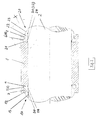
- FIG. 1 shows a section through a plain bearing 1 in the form a rolled or turned metal bushing, which acts as a sliding partner a shaft / axis 2 is assigned.
- the slide bearing 1 has recesses 3, 4 on, in the lip seals 10, 20 of the thickness D preferably intervene with an elastomer.
- the lip seals 10, 20 each consist of one Holding part 11, 21, a support part 12, 22 and one biased sealing lip 13, 23, which in the installed state of the bearing 1 rests linearly on the shaft / axis 2.
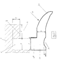
- the holding parts 11, 21 each have a holding foot 11 ', 21' with which they fit into assigned ring grooves 5, 6 (groove width B, Groove depth T) of the recesses 3, 4 are pressed.
- the width F of the holding foot 11 ', 21' is greater than that Groove width B (F> B), cf. especially Fig. 3. That through the Pressing shifted sealing material is from the ring groove 5, 6 added.
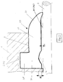
- the subsequent support part 12, 22 is supported on the Support edge 7, 8 from.
- the sealing lips 13, 23 are outside the End faces attached to the support parts 12, 22.
- Through the pre-stressed form is a secure contact of the sealing lip 13, 23 guaranteed on the shaft / axis 2, so that together with the tapered, curved outer shape of the sealing lip 13, 23 in particular a harmful entry of water is safely avoided. Due to the small distance between Support part 12, 22 and sealing lip support does not occur Deflection of the support part 12, 22, which otherwise leads to frictional contact could lead between shaft / axis 2 and support member 12, 22.
- the sealing body of the lip seals 10, 20 (which in the essentially from the holding part 11, 21 and the supporting part 12, 22 exists) has a distance to avoid friction from the shaft / axis 2 so that each is ring-shaped Form cavities 30, 31 of ring thickness A. These cavities 30, 31 can up to the linear contact point of the sealing lips 13, 23 on the shaft / axis 2 with lubricant 32 fill out.
- a depot 14, 24 for lubricant 32 be arranged, the height H of which is at least twice Ring thickness A corresponds.
- a shaft 2 made of hardened and ground steel with an outer diameter of 40 mm (40e6) served as counter-rotating partner. The long-term test carried out in the mixed friction area showed significant improvements in running time compared to the prior art.
Abstract
Description
Die Erfindung betrifft ein Gleitlager mit integrierter
Lippendichtung nach dem Oberbegriff des Anspruchs 1.The invention relates to a plain bearing with an integrated
Lip seal according to the preamble of
Die betriebssichere Funktion der Gleitlager in gedrehter oder gerollter Ausführung erfordert eine ausreichende Abdichtung des Lagerinnenraums, um den Zutritt von Fremdstoffen zu verhindern.The reliable function of the plain bearing in turned or rolled execution requires sufficient Sealing of the warehouse interior to prevent the entry of foreign substances to prevent.
Gleitlager der genannten Art (etwa nach der DE-PS 3.412.562) werden unter Verwendung von festem Schmierstoff für wartungsfreie Lager eingesetzt.Plain bearings of the type mentioned (for example according to DE-PS 3.412.562) are made using solid lubricant for maintenance-free Bearings used.
Halterung und Aufbau der dortigen Lippendichtung sind jedoch relativ kompliziert, weil die Halteteile der Lippendichtung mit zwei Stegen in zwei Ringnuten eingesetzt werden müssen. Außerdem ist die Vorrichtung zur Herstellung der Ringnuten aufwendig. Für dünnwandige gerollte Buchsen läßt sich diese Dichtung nicht verwenden.Bracket and structure of the lip seal there are relatively complicated because the retaining parts of the lip seal used with two webs in two ring grooves Need to become. In addition, the device for manufacturing the ring grooves are expensive. For thin-walled rolled bushings this seal cannot be used.
Der Erfindung liegt die Aufgabe zugrunde, Gleitlager der genannten Art so auszubilden, daß sie nicht nur einfach und preiswert herstellbar sind, sondern auch besonders bei fettgeschmierten Lagerstellen im rauhen Mischreibungsbetrieb eingesetzt werden können, wo neben mehrmaligem Nachschmieren während der Lebensdauer auch mit Schmutz und Abrieb gerechnet werden muß.The invention has for its object the plain bearing mentioned type so that they are not only simple and are inexpensive to manufacture, but also especially at grease-lubricated bearings in rough mixed friction operation can be used where, in addition to repeated relubrication Dirt and abrasion are also expected during the service life must become.
Die Aufgabe wird erfindungsgemäß dadurch gelöst, daß das Halteteil ausschließlich mit einem Hatte fuß versehen ist, der in eine Ringnut der Ausnehmung eingepreßt ist. The object is achieved in that the Holding part is provided exclusively with a had foot, which is pressed into an annular groove of the recess.
Die Ringnut zur Befestigung der Lippendichtung läßt sich auf einfache Weise herstellen, da zum Einstich keine komplizierten Formstähle nötig sind. Die Montage der Lippendichtung ist ohne jegliches Werkzeug leicht möglich und kann auch noch nachträglich vorgenommen werden.The ring groove for attaching the lip seal can be opened easy to make because there are no complicated punctures Molded steels are necessary. The assembly of the lip seal is easily possible without any tools and can also still be made later.
Nach einer bevorzugten Ausführung der Erfindung beträgt die Nutbreite B ≥ 0,6 mm, insbes. 0,8 - 1,5 mm, und die Nuttiefe T ≥ 0,5 mm. Die Breite des Stützrandes für das Stützteil wird vorzugsweise zu S ≥ 0,5 mm, insbes. 0,7 - 1,5 mm, ausgewählt.According to a preferred embodiment of the invention the groove width B is ≥ 0.6 mm, esp. 0.8 - 1.5 mm, and the groove depth T ≥ 0.5 mm. The width of the Support edge for the support part is preferably S ≥ 0.5 mm, in particular 0.7 - 1.5 mm, selected.
Die Dicke der Lippendichtung beträgt vorzugsweise D ≥ 0,5 mm.The thickness of the lip seal is preferably D ≥ 0.5 mm.
Durch diese erfindungsgemäße Auswahl der Parameter läßt sich die vorgeschlagene Dichtung der Gleitlager nicht nur bei dickwandigen, sondern auch bei dünnwandigen, gerollten Gleitlagerbuchsen ab etwa 1,5 mm Wanddicke einsetzen.This selection of the parameters according to the invention allows the proposed seal of the plain bearing not only thick-walled, but also thin-walled, rolled Insert plain bearing bushes from a wall thickness of approximately 1.5 mm.
In weiterer Ausgestaltung der Erfindung beträgt die Ringdicke des ringförmigen Hohlraums vorzugsweise A ≥ 0,1 mm, wobei es sich empfiehlt, diesen ringförmigen Hohlraum zur weiteren Abdichtung mit Schmierstoff auszufüllen. Dieser Fettkragen bewirkt, daß trotz der äußeren Dichtlippe eintretende Fremdstoffe zurückgehalten werden und nicht in die Gleitfläche der Lagerung vordringen können. Zudem wird die Lebensdauer des Gleitlagers erhöht.In a further embodiment of the invention, the ring thickness is the annular cavity, preferably A ≥ 0.1 mm, it is advisable to use this annular cavity fill further seal with lubricant. This Fat collar causes that despite the outer sealing lip incoming foreign substances are retained and not in can penetrate the sliding surface of the bearing. In addition, the life of the plain bearing increases.
Um insbesondere beim Nachschmiervorgang ein gleichmäßiges
Austreten des Fettes und des darin gebundenen Abriebes zu
gewährleisten, empfiehlt es sich, daß die zur Welle gerichtete
Unterseite von Halteteil und Stützteil glatt ausgebildet
ist.
Weiterhin ist es vorteilhaft, im Halteteil ein Depot für
Schmierstoff anzuordnen, wobei insbesondere dessen Höhe H
mindestens der zweifachen Ringdicke A entsprechen sollte.
Vorzugsweise ist die Dichtlippe ohne Absatz am Stützteil
angesetzt, d. h. ohne einen Absatz, in dem sich Schmutz od.
dgl. ablagern könnte.In order to ensure a uniform escape of the grease and the abrasion bound therein, in particular during the relubrication process, it is recommended that the underside of the holding part and the supporting part facing the shaft be smooth.
Furthermore, it is advantageous to arrange a deposit for lubricant in the holding part, in particular its height H should correspond to at least twice the ring thickness A. The sealing lip is preferably attached to the support part without a shoulder, ie without a shoulder in which dirt or the like could be deposited.
Die Erfindung wird anhand der folgenden Ausführungsbeispiele näher erläutert. Es zeigt
- Fig.1
- einen Schnitt durch ein erfindungsgemäßes Gleitlager,
- Fig.2
- das Detail X nach Fig.1 im vergrößerten Maßstab und
- Fig.3
- im vergrößerten Maßstab das Einsetzen der Lippendichtung in die zugeordnete Ausnehmung.
- Fig. 1
- a section through a plain bearing according to the invention,
- Fig. 2
- the detail X of Figure 1 on an enlarged scale and
- Fig. 3
- inserting the lip seal into the associated recess on an enlarged scale.
Fig.1 zeigt einen Schnitt durch ein Gleitlager 1 in Form
einer gerollten oder gedrehten Metallbuchse, dem als Gleitpartner
eine Welle/Achse 2 zugeordnet ist.1 shows a section through a plain bearing 1 in the form
a rolled or turned metal bushing, which acts as a sliding partner
a shaft /
Stirnseitig weist das Gleitlager 1 jeweils Ausnehmungen 3, 4
auf, in die Lippendichtungen 10, 20 der Dicke D aus vorzugsweise
einem Elastomer kraftschlüssig eingreifen. Die Lippendichtungen
10, 20 ihrerseits bestehen jeweils aus einem
Halteteil 11, 21, einem Stützteil 12, 22 und einer
vorgespannten Dichtlippe 13, 23, die im eingebauten Zustand
des Lagers 1 linienförmig auf der Welle/Achse 2 aufliegt.
Die Halteteile 11, 21 weisen jeweils einen Haltefuß 11', 21'
auf, mit dem sie in zugeordnete Ringnuten 5, 6 (Nutbreite B,
Nuttiefe T) der Ausnehmungen 3, 4 eingepreßt werden. Dabei
ist die Breite F des Haltefußes 11', 21' größer als die
Nutbreite B (F > B), vgl. insbesondere Fig.3. Das durch die
Pressung verlagerte Dichtungsmaterial wird von der Ringnut
5, 6 aufgenommen.On the face side, the slide bearing 1 has
Das anschließende Stützteil 12, 22 stützt sich an dem
Stützrand 7, 8 ab. Die Dichtlippen 13, 23 sind außerhalb der
Stirnflächen an den Stützteilen 12, 22 angesetzt. Durch die
vorgespannte Form wird eine sichere Anlage der Dichtlippe
13, 23 auf der Welle/Achse 2 gewährleistet, so daß zusammen
mit der spitz zulaufenden, gewölbten Außenform der Dichtlippe
13, 23 insbesondere ein schädlicher Wassereintritt
sicher vermieden wird. Durch den geringen Abstand zwischen
Stützteil 12, 22 und Dichtlippenauflage kommt es zu keinem
Durchbiegen des Stützteils 12, 22, was sonst zu Reibkontakt
zwischen Welle/Achse 2 und Stützteil 12, 22 führen könnte.The
Der Dichtungskörper der Lippendichtungen 10, 20 (der im
wesentlichen aus dem Halteteil 11, 21 und dem Stützteil 12,
22 besteht) weist zur Vermeidung von Reibung einen Abstand
von der Welle/Achse 2 auf, so daß sich jeweils ringförmige
Hohlräume 30, 31 der Ringdicke A ausbilden. Diese Hohlräume
30, 31 können bis zum linienförmigen Anlagepunkt der Dichtlippen
13, 23 auf der Welle/Achse 2 mit Schmierstoff 32
ausgefüllt werden. In vorteilhafter Weise kann jeweils im
Halteteil 11, 21 ein Depot 14, 24 für Schmierstoff 32
angeordnet sein, dessen Höhe H mindestens der zweifachen
Ringdicke A entspricht. The sealing body of the
In ein Gehäuse mit einem Innendurchmesser von 44 mm (Ø 44
H7) wurde eine dünnwandige, gerollte Lagerbuchse 1 aus
Zinnbronze (CuSn8) mit folgenden Abmessungen eingepreßt:
Außendurchmesser 44 mm x Innendurchmesser 40 mm x Breite
40 mm. Am Gleitlager 1 waren beidseits erfindungsgemäße
Dichtungen 10, 20 aus einem Elastomer (NBR) angebracht. Als
Gegenlaufpartner diente eine Welle 2 aus gehärtetem und
geschliffenem Stahl mit einem Außendurchmesser von 40 mm
(40e6).
Es zeigten sich bei dem durchgeführten Langzeitversuch im
Mischreibungsgebiet gegenüber dem bisherigen Stand der
Technik deutliche Laufzeitverbesserungen.A thin-walled, rolled
The long-term test carried out in the mixed friction area showed significant improvements in running time compared to the prior art.
Claims (12)
- Sliding bearing (1) having, arranged in its end regions, inner recesses (3, 4) in which a lip seal (10, 20), which runs around in a circumferential direction and comprises a holding portion (11, 21), a sealing lip (13, 23) and, arranged therebetween, a support portion (12, 22), is fixed by the non-positive engagement of the holding portion (11, 21) in the recess (3, 4),characterised in thatthe prestressed sealing lip (13, 23), adjoining the support portion (12, 22) outside the end face, projecting beyond the end face and being supported in a linear manner on an associated sliding partner (2) andan annular cavity (30, 31) of annular thickness A and open towards the inside of the sliding bearing (1) being formed between the holding portion (11, 21) and the support portion (12, 22), on the one hand, and the associated sliding partner (2), on the other hand,the holding portion (11, 21) is provided only with a holding foot (11', 21') which is pressed into an annular slot (5, 6) of the recess (3, 4).
- Sliding bearing according to claim 1, characterised in that the slot width B is ≥ 0.6 mm and the slot depth T is ≥ 0.5 mm.
- Sliding bearing according to claim 2, characterised in that the slot width B is from 0.8 to 1.5 mm.
- Sliding bearing according to one or more of claims 1 to 3, characterised in that the width of the support edge (7, 8) for the support portion (12, 22) S is ≥ 0.5 mm.
- Sliding bearing according to claim 4, characterised in that the width S is from 0.7 to 1.5 mm.
- Sliding bearing according to one or more of claims 1 to 5, characterised in that the thickness of the lip seal (10, 20) D is ≥ 0.5 mm.
- Sliding bearing according to one or more of claims 1 to 6, characterised in that the annular thickness of the annular cavity (30, 31) A is ≥ 0.1 mm.
- Sliding bearing according to one or more of claims 1 to 7, characterised in that the annular cavity (30, 31) is filled with lubricant (32).
- Sliding bearing according to one or more of claims 1 to 8, characterised in that the underside, facing towards the associated sliding partner (2), of the holding portion (11, 21) and of the support portion (12, 22) has a smooth form.
- Sliding bearing according to one or more of claims 1 to 9, characterised in that a depot (14, 24) for lubricant (32) is arranged in the holding portion (11, 21).
- Sliding bearing according to claim 10, characterised in that the height H of the depot (14, 24) is at least double the annular thickness A.
- Sliding bearing according to one or more of claims 1 to 11, characterised in that the sealing lip (13, 23) adjoins the support portion (12, 22) without a shoulder.
Applications Claiming Priority (2)
| Application Number | Priority Date | Filing Date | Title |
|---|---|---|---|
| DE4401526A DE4401526C1 (en) | 1994-01-20 | 1994-01-20 | Sliding-contact bearing with integrated lip seal |
| DE4401526 | 1994-01-20 |
Publications (2)
| Publication Number | Publication Date |
|---|---|
| EP0664409A1 EP0664409A1 (en) | 1995-07-26 |
| EP0664409B1 true EP0664409B1 (en) | 1999-03-03 |
Family
ID=6508277
Family Applications (1)
| Application Number | Title | Priority Date | Filing Date |
|---|---|---|---|
| EP94120361A Expired - Lifetime EP0664409B1 (en) | 1994-01-20 | 1994-12-22 | Sliding contact bearing with integrated lip seal |
Country Status (5)
| Country | Link |
|---|---|
| US (1) | US5490731A (en) |
| EP (1) | EP0664409B1 (en) |
| AT (1) | ATE177171T1 (en) |
| DE (2) | DE4401526C1 (en) |
| FI (1) | FI110811B (en) |
Families Citing this family (15)
| Publication number | Priority date | Publication date | Assignee | Title |
|---|---|---|---|---|
| DE4428603A1 (en) * | 1994-08-12 | 1996-02-15 | Abs Pump Center Gmbh | Agitator |
| DE29611964U1 (en) * | 1996-07-10 | 1996-09-05 | Bpw Bergische Achsen Kg | Plain bearing bush |
| DE29611970U1 (en) * | 1996-07-10 | 1996-09-05 | Bpw Bergische Achsen Kg | Support bearing for the brake camshaft of a vehicle brake |
| DE19639798C5 (en) * | 1996-09-27 | 2013-11-28 | Trelleborg Sealing Solutions Germany Gmbh | Single-stripper |
| CN1165697C (en) * | 1996-12-16 | 2004-09-08 | 株式会社理光 | Seal-sliding method, method for recovering seal lip from its bent state, and seal-sliding-in apparatus |
| DE19757021A1 (en) * | 1997-12-20 | 1999-07-15 | Federal Mogul Wiesbaden Gmbh | Bearing bush and process for its manufacture |
| US6050572A (en) * | 1998-03-09 | 2000-04-18 | Bal Seal Engineering Company, Inc. | Rotary cartridge seals with retainer |
| JP2003033639A (en) * | 2001-07-25 | 2003-02-04 | Shin Meiwa Ind Co Ltd | Underwater mixer |
| DE20202179U1 (en) * | 2002-02-14 | 2002-04-18 | Burgmann Dichtungswerke Gmbh | Secondary sealing element for a mechanical seal arrangement, in particular for sterile applications |
| EP2048385A1 (en) * | 2007-10-11 | 2009-04-15 | Carl Freudenberg KG | Bearing assembly |
| WO2013075739A1 (en) * | 2011-11-23 | 2013-05-30 | Abb Research Ltd | A sealing system, an industrial robot with a sealing system, and a method for providing a sealing surface |
| DE102015117754A1 (en) | 2015-10-19 | 2017-04-20 | Federal-Mogul Deva Gmbh | Plain bearing bush with integrated sealing lip |
| DE102017123118A1 (en) | 2017-10-05 | 2019-04-11 | Kiekert Ag | Magnetorheological actuator with bearing arrangement |
| DE102019105112A1 (en) * | 2019-02-28 | 2020-09-03 | Carl Freudenberg Kg | Bearing bush |
| EP4039994A1 (en) * | 2021-02-08 | 2022-08-10 | Goodrich Actuation Systems Limited | Thrust bearing seal for thin wing multi slice rga |
Family Cites Families (7)
| Publication number | Priority date | Publication date | Assignee | Title |
|---|---|---|---|---|
| US3563556A (en) * | 1969-07-30 | 1971-02-16 | Federal Mogul Corp | Boot-type shaft seal unit |
| US3804217A (en) * | 1972-03-13 | 1974-04-16 | Monroe Belgium Nv | Pressurized shock absorber |
| DE2459732A1 (en) * | 1974-12-18 | 1976-06-24 | Wolfgang Dr Kranert | Circular flexible seal for shafts - has outwards projecting collar for easy replacement without dismantling of equipment |
| DE2813163A1 (en) * | 1978-03-25 | 1979-09-27 | Merkel Kg Martin | SEALING RING, IN PARTICULAR WIPER RING, MADE OF ELASTOMERIC MATERIAL |
| US4210339A (en) * | 1978-12-26 | 1980-07-01 | Towmotor Corporation | Seal and seal assembly |
| US4243232A (en) * | 1979-10-29 | 1981-01-06 | Garlock Inc. | One-piece oil seal and boot seal |
| DE3412562A1 (en) * | 1983-05-14 | 1984-11-15 | Gerhard 3012 Langenhagen Lorenz | Device for sealing off bearings, in particular encapsulated maintenance-free bearings |
-
1994
- 1994-01-20 DE DE4401526A patent/DE4401526C1/en not_active Expired - Fee Related
- 1994-12-22 DE DE59407880T patent/DE59407880D1/en not_active Expired - Lifetime
- 1994-12-22 AT AT94120361T patent/ATE177171T1/en not_active IP Right Cessation
- 1994-12-22 EP EP94120361A patent/EP0664409B1/en not_active Expired - Lifetime
-
1995
- 1995-01-12 US US08/371,812 patent/US5490731A/en not_active Expired - Lifetime
- 1995-01-18 FI FI950205A patent/FI110811B/en not_active IP Right Cessation
Also Published As
| Publication number | Publication date |
|---|---|
| FI110811B (en) | 2003-03-31 |
| DE59407880D1 (en) | 1999-04-08 |
| ATE177171T1 (en) | 1999-03-15 |
| DE4401526C1 (en) | 1994-12-15 |
| US5490731A (en) | 1996-02-13 |
| FI950205A0 (en) | 1995-01-18 |
| FI950205A (en) | 1995-07-21 |
| EP0664409A1 (en) | 1995-07-26 |
Similar Documents
| Publication | Publication Date | Title |
|---|---|---|
| EP0664409B1 (en) | Sliding contact bearing with integrated lip seal | |
| EP1181462B1 (en) | Ball joint | |
| EP0485696B1 (en) | Elastic bearing | |
| DE3542143C2 (en) | Seal for sliding connection | |
| EP0485697A2 (en) | Elastic bearing | |
| DE1068517B (en) | ||
| DE2601798C2 (en) | camp | |
| DD262894A5 (en) | DEVICE FOR SEALING THE STORAGE BUCKET OF A CRANKSHAFT | |
| EP0922595A2 (en) | Axle for sun visor | |
| DE2759000A1 (en) | FLAP VALVE | |
| DE3207488C2 (en) | ||
| DE3209572A1 (en) | SPHERICAL BEARING | |
| DE1675099A1 (en) | Roller bearing | |
| DE19915975B4 (en) | roller bearing | |
| DE3017452A1 (en) | Slide bearing for universal joint journals - contains U=shaped slide insert with longitudinal grooves, and projecting sealing lips | |
| DE3201147A1 (en) | ROLLER BODY BEARING TELESCOPIC COUPLING | |
| DE2711882A1 (en) | BALL BUSH | |
| DE2743825A1 (en) | CHISEL | |
| DE10004438A1 (en) | Bearing assembly suitable for the mounting of steering columns has resilient bushing | |
| DE2429598A1 (en) | CAPSULA LIKE CAMP | |
| DE1575432C2 (en) | Method for manufacturing a spherical plain bearing | |
| DE3109787A1 (en) | SEALED ROLLER BEARING | |
| DE10110668B4 (en) | Kurvennuttrieb | |
| DE2700725C2 (en) | Intermediate screw conveyor storage | |
| DE6944082U (en) | MECHANICAL SEAL. |
Legal Events
| Date | Code | Title | Description |
|---|---|---|---|
| PUAI | Public reference made under article 153(3) epc to a published international application that has entered the european phase |
Free format text: ORIGINAL CODE: 0009012 |
|
| 17P | Request for examination filed |
Effective date: 19941222 |
|
| AK | Designated contracting states |
Kind code of ref document: A1 Designated state(s): AT CH DE FR GB IT LI SE |
|
| 17Q | First examination report despatched |
Effective date: 19970624 |
|
| GRAG | Despatch of communication of intention to grant |
Free format text: ORIGINAL CODE: EPIDOS AGRA |
|
| GRAG | Despatch of communication of intention to grant |
Free format text: ORIGINAL CODE: EPIDOS AGRA |
|
| GRAH | Despatch of communication of intention to grant a patent |
Free format text: ORIGINAL CODE: EPIDOS IGRA |
|
| GRAH | Despatch of communication of intention to grant a patent |
Free format text: ORIGINAL CODE: EPIDOS IGRA |
|
| GRAA | (expected) grant |
Free format text: ORIGINAL CODE: 0009210 |
|
| AK | Designated contracting states |
Kind code of ref document: B1 Designated state(s): AT CH DE FR GB IT LI SE |
|
| REF | Corresponds to: |
Ref document number: 177171 Country of ref document: AT Date of ref document: 19990315 Kind code of ref document: T |
|
| REG | Reference to a national code |
Ref country code: CH Ref legal event code: EP |
|
| REF | Corresponds to: |
Ref document number: 59407880 Country of ref document: DE Date of ref document: 19990408 |
|
| ITF | It: translation for a ep patent filed |
Owner name: JACOBACCI & PERANI S.P.A. |
|
| REG | Reference to a national code |
Ref country code: CH Ref legal event code: NV Representative=s name: A. BRAUN, BRAUN, HERITIER, ESCHMANN AG PATENTANWAE |
|
| ET | Fr: translation filed | ||
| GBT | Gb: translation of ep patent filed (gb section 77(6)(a)/1977) |
Effective date: 19990521 |
|
| PLBE | No opposition filed within time limit |
Free format text: ORIGINAL CODE: 0009261 |
|
| STAA | Information on the status of an ep patent application or granted ep patent |
Free format text: STATUS: NO OPPOSITION FILED WITHIN TIME LIMIT |
|
| 26N | No opposition filed | ||
| REG | Reference to a national code |
Ref country code: GB Ref legal event code: IF02 |
|
| REG | Reference to a national code |
Ref country code: CH Ref legal event code: PFA Owner name: WIELAND-WERKE AG Free format text: WIELAND-WERKE AG#GRAF-ARCO-STRASSE 36#89079 ULM (DE) -TRANSFER TO- WIELAND-WERKE AG#GRAF-ARCO-STRASSE 36#89079 ULM (DE) |
|
| PGFP | Annual fee paid to national office [announced via postgrant information from national office to epo] |
Ref country code: SE Payment date: 20091207 Year of fee payment: 16 Ref country code: CH Payment date: 20091215 Year of fee payment: 16 Ref country code: AT Payment date: 20091211 Year of fee payment: 16 |
|
| PGFP | Annual fee paid to national office [announced via postgrant information from national office to epo] |
Ref country code: IT Payment date: 20091218 Year of fee payment: 16 Ref country code: GB Payment date: 20091216 Year of fee payment: 16 Ref country code: FR Payment date: 20091221 Year of fee payment: 16 |
|
| PGFP | Annual fee paid to national office [announced via postgrant information from national office to epo] |
Ref country code: DE Payment date: 20091231 Year of fee payment: 16 |
|
| REG | Reference to a national code |
Ref country code: CH Ref legal event code: PL |
|
| GBPC | Gb: european patent ceased through non-payment of renewal fee |
Effective date: 20101222 |
|
| PG25 | Lapsed in a contracting state [announced via postgrant information from national office to epo] |
Ref country code: AT Free format text: LAPSE BECAUSE OF NON-PAYMENT OF DUE FEES Effective date: 20101222 |
|
| REG | Reference to a national code |
Ref country code: FR Ref legal event code: ST Effective date: 20110831 |
|
| REG | Reference to a national code |
Ref country code: SE Ref legal event code: EUG |
|
| PG25 | Lapsed in a contracting state [announced via postgrant information from national office to epo] |
Ref country code: SE Free format text: LAPSE BECAUSE OF NON-PAYMENT OF DUE FEES Effective date: 20101223 |
|
| PG25 | Lapsed in a contracting state [announced via postgrant information from national office to epo] |
Ref country code: LI Free format text: LAPSE BECAUSE OF NON-PAYMENT OF DUE FEES Effective date: 20101231 Ref country code: CH Free format text: LAPSE BECAUSE OF NON-PAYMENT OF DUE FEES Effective date: 20101231 Ref country code: FR Free format text: LAPSE BECAUSE OF NON-PAYMENT OF DUE FEES Effective date: 20110103 |
|
| REG | Reference to a national code |
Ref country code: DE Ref legal event code: R119 Ref document number: 59407880 Country of ref document: DE Effective date: 20110701 |
|
| PG25 | Lapsed in a contracting state [announced via postgrant information from national office to epo] |
Ref country code: GB Free format text: LAPSE BECAUSE OF NON-PAYMENT OF DUE FEES Effective date: 20101222 Ref country code: DE Free format text: LAPSE BECAUSE OF NON-PAYMENT OF DUE FEES Effective date: 20110701 |
|
| PG25 | Lapsed in a contracting state [announced via postgrant information from national office to epo] |
Ref country code: IT Free format text: LAPSE BECAUSE OF NON-PAYMENT OF DUE FEES Effective date: 20101222 |