EP0664265A1 - Automated installation for pallet loading and unloading on lorries, especially at automated warehouses - Google Patents
Automated installation for pallet loading and unloading on lorries, especially at automated warehouses Download PDFInfo
- Publication number
- EP0664265A1 EP0664265A1 EP95500003A EP95500003A EP0664265A1 EP 0664265 A1 EP0664265 A1 EP 0664265A1 EP 95500003 A EP95500003 A EP 95500003A EP 95500003 A EP95500003 A EP 95500003A EP 0664265 A1 EP0664265 A1 EP 0664265A1
- Authority
- EP
- European Patent Office
- Prior art keywords
- pallets
- loading
- platform
- automated
- unloading
- Prior art date
- Legal status (The legal status is an assumption and is not a legal conclusion. Google has not performed a legal analysis and makes no representation as to the accuracy of the status listed.)
- Granted
Links
- 238000009434 installation Methods 0.000 title claims abstract description 13
- 238000009987 spinning Methods 0.000 claims abstract description 5
- 238000006073 displacement reaction Methods 0.000 claims description 2
- 238000000034 method Methods 0.000 description 6
- 238000002360 preparation method Methods 0.000 description 2
- 230000000295 complement effect Effects 0.000 description 1
- 238000009826 distribution Methods 0.000 description 1
- 238000004519 manufacturing process Methods 0.000 description 1
- 230000005055 memory storage Effects 0.000 description 1
- 238000004806 packaging method and process Methods 0.000 description 1
- 238000000926 separation method Methods 0.000 description 1
Images


Classifications
-
- B—PERFORMING OPERATIONS; TRANSPORTING
- B65—CONVEYING; PACKING; STORING; HANDLING THIN OR FILAMENTARY MATERIAL
- B65G—TRANSPORT OR STORAGE DEVICES, e.g. CONVEYORS FOR LOADING OR TIPPING, SHOP CONVEYOR SYSTEMS OR PNEUMATIC TUBE CONVEYORS
- B65G67/00—Loading or unloading vehicles
- B65G67/02—Loading or unloading land vehicles
- B65G67/04—Loading land vehicles
- B65G67/20—Loading covered vehicles
-
- B—PERFORMING OPERATIONS; TRANSPORTING
- B65—CONVEYING; PACKING; STORING; HANDLING THIN OR FILAMENTARY MATERIAL
- B65G—TRANSPORT OR STORAGE DEVICES, e.g. CONVEYORS FOR LOADING OR TIPPING, SHOP CONVEYOR SYSTEMS OR PNEUMATIC TUBE CONVEYORS
- B65G67/00—Loading or unloading vehicles
- B65G67/02—Loading or unloading land vehicles
-
- B—PERFORMING OPERATIONS; TRANSPORTING
- B66—HOISTING; LIFTING; HAULING
- B66C—CRANES; LOAD-ENGAGING ELEMENTS OR DEVICES FOR CRANES, CAPSTANS, WINCHES, OR TACKLES
- B66C11/00—Trolleys or crabs, e.g. operating above runways
-
- B—PERFORMING OPERATIONS; TRANSPORTING
- B66—HOISTING; LIFTING; HAULING
- B66F—HOISTING, LIFTING, HAULING OR PUSHING, NOT OTHERWISE PROVIDED FOR, e.g. DEVICES WHICH APPLY A LIFTING OR PUSHING FORCE DIRECTLY TO THE SURFACE OF A LOAD
- B66F9/00—Devices for lifting or lowering bulky or heavy goods for loading or unloading purposes
- B66F9/06—Devices for lifting or lowering bulky or heavy goods for loading or unloading purposes movable, with their loads, on wheels or the like, e.g. fork-lift trucks
- B66F9/075—Constructional features or details
- B66F9/08—Masts; Guides; Chains
- B66F9/10—Masts; Guides; Chains movable in a horizontal direction relative to truck
-
- B—PERFORMING OPERATIONS; TRANSPORTING
- B66—HOISTING; LIFTING; HAULING
- B66F—HOISTING, LIFTING, HAULING OR PUSHING, NOT OTHERWISE PROVIDED FOR, e.g. DEVICES WHICH APPLY A LIFTING OR PUSHING FORCE DIRECTLY TO THE SURFACE OF A LOAD
- B66F9/00—Devices for lifting or lowering bulky or heavy goods for loading or unloading purposes
- B66F9/06—Devices for lifting or lowering bulky or heavy goods for loading or unloading purposes movable, with their loads, on wheels or the like, e.g. fork-lift trucks
- B66F9/075—Constructional features or details
- B66F9/12—Platforms; Forks; Other load supporting or gripping members
- B66F9/122—Platforms; Forks; Other load supporting or gripping members longitudinally movable
Definitions
- the invention which is the subject matter of this report refers to an automated installation for transfer of pallets from highly-automated warehouses to lorries and viceversa, although it can also be installed - for many reasons - in warehouses either scarcely or not-automated at all.
- the basis of this installation is an automated system for the loading of pallets by means of a continuous double line and up to the sides of the loading area of each one of the quays including the joint front aligning terminal for every two pallets.
- the basic device of this installation is a telescopic crane which travels along an aligned frame and carries a trolley with free-spinning telescopic wheels and the relevant shovels to handle the paired pallets at their bottom.
- the new technology enables the almost complete automation of warehouses. Since they are dynamically configured, they incorporate a high rationalization for the distribution of products along with an accurate and rigorous knowledge of the status of the warehouse which is instantaneously updated as well as an automated loading and unloading access depending on the alignment of the stands between the rails where the cranes for the transfer of goods circulate either by means of multiple access rails or a crane for each rail and a parallel double rank of stands.
- these warehouses include a handling area located immediately before the warehouse itself.
- One of the possible and common operations which are carried out in such area is the palletting of goods received. This area is located between the warehouse and the production area.
- Patent P8600455 "Programmable trolley for the preparation of purchase orders”
- Patent P 9100230 “Packaging machine”
- U9300109 "Palleted load packager” have been developed by the same person who is involved in the subject of warehouse automation.
- the basis of this invention is a quay loading terminal either rail-guided, belt-guided or guided by rollers provided that the load to be shipped duly palletted is placed on two parallel ranks on each quay on both sides of the inner extension of the sides of the lorry.
- the basis of the preferred selected execution is a telescopic crane located between a consecutive series of frames inside the quay and aligned towards the same direction that the loading platform of the lorry to enable the telescopic devices of the crane to reach the bottom of the lorry platform.
- This crane incorporates an advancing tandem and a telescopic device. At the outer side it also incorporates a conventional lifting and descending device to enable the vertical movement of the paired pallet handling shovels. This paired configuration enables the front aligned loading of the lorry by successive pairs of pallets.
- another telescopic device helps the supporting rear and free-spinning wheels to descend.
- This device starts its operation once the advancing tandem has been introduced inside the platform of the lorry along with the two first front-aligned pallets so that the telescopic mechanism of the crane can start its operation to introduce the goods which are supported by the above-mentioned wheels into the inner end of the platform.
- the shipping devices either belts, rollers or other means - convey the consecutive aligned pallets coming opposed feeding lines to a common meeting point located precisely in front of the platform of the lorry to be loaded.
- the pallets are placed by pairs in an opposed and closed position. The separation between pallets can vary a few centimetres only.
- the crane Before carrying out such loading operation, the crane extends the telescopic system and checks through the appropriate means - preferably a laser alignment system - the alignment of the lorry and hence the lorry platform and the edge of the quay as well as the height of such platform compared with the surface of the quay.
- the loading operation starts in the preset direction and when two aligned pallets are deposited the telescopic arms operated until they reach the end of their travel and come into contact with the last row of pallets previously placed. This operation can be carried out as many times as necessary to complete the loading of the lorry.
- the advancing tandem and the telescopic arms are forced to go backwards through the row of frames the distance needed to continue such loading operations but each time closer to the last one and moving away from such frames.
- the backwards movements of the telescopic crane are logically carried out at the consecutive aligned placement intervals of the paired pallets.
- a closing and grouping device for such paired pallets is located at the head of the loading which consists of two oblique guides which meet towards the platform so that both pallets become closer evenly and simultaneously.
- the general unloading process calls for the same steps as the loading process while following an opposite layout verifying all the locations of the paired pallets which are front-aligned so that the shovels can spin adequately and adapt to the minimum differences in the placement of the pallets occurred during the shipping and even checking whether the last pair of pallets has been removed.
- Figure 1 shows a general schematic perspective view of the loading quay with a lorry parked and during the automated loading or unloading process. In such figure some of the enhancements which are the subject matter of this invention can be observed.
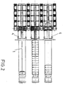
- Figure 2 shows a general and schematic plan view of the installation incorporating such enhancements.
- the different loading positions of different lorries, depending on the loading level, can be observed.
- Figure 3 shows a schematic front view of the referenced installation where the different operating aspects can be observed from the top to the bottom: the position of the lorry to start the loading operations, the advancing tandem being introduced in the lorry and lowering its supporting wheels, the beginning of the operation of the telescopic arms, the contact at the end of their travel and, at the bottom, the total backwards movement of the telescopic arms and the final placement with the advancing tandem before the removal of such tandem and of the wheels to initiate a new cycle.
- the invention for the automated loading and unloading of lorries incorporates a telescopic crane (1), with an advancing tandem and aligned with the axis of the loading platform of the lorry, so that it can reach the end of the platform.
- the telescopic device Apart from the telescopic device, it also incorporates a combined vertical and horizontal displacement system for the shovels (2), for the handling of pallets in successive pairs and another telescopic device to lower and hide the rear, free-spinning, load supporting wheels that incorporate a hydraulic or pneumatic sensor.
- the device starts its operation when the advancing tandem has been introduced along with the first row of pallets inside the platform of the lorry. Then the telescopic mechanism of the crane itself starts its operation by pushing the pallets inside the platform.
- the perpendicular and height alignment of the walls and the bottom of the platform compared with the edge of the quay are previously checked as well as during each loading operation displacing the telescopic arms until they reach the last row of pallets placed thus completing the loading by means of a backwards movement of the advancing tandem and the telescopic arms.
- An device (4) to approach these pairs of pallets already grouped is available at the head of the loading line by means of oblique opposed guides which are connected to the pallet and the load. While the pallets are introduced inside the platform and before lowering the supporting wheels, the guides bring the pallets nearer thanks to such oblique layout.
- This device also serves as a fitting mean at the sides of the lorry platform acting as an extension of the quay.
- this installation incorporates a computerized control system formed by several axes to make a complete study and memory storage of the lorry platform for its later loading or unloading.
Landscapes
- Engineering & Computer Science (AREA)
- Mechanical Engineering (AREA)
- Transportation (AREA)
- Structural Engineering (AREA)
- Aviation & Aerospace Engineering (AREA)
- Civil Engineering (AREA)
- Life Sciences & Earth Sciences (AREA)
- Geology (AREA)
- Ship Loading And Unloading (AREA)
- Loading Or Unloading Of Vehicles (AREA)
- Warehouses Or Storage Devices (AREA)
Abstract
Description
- The invention which is the subject matter of this report refers to an automated installation for transfer of pallets from highly-automated warehouses to lorries and viceversa, although it can also be installed - for many reasons - in warehouses either scarcely or not-automated at all.
- The basis of this installation is an automated system for the loading of pallets by means of a continuous double line and up to the sides of the loading area of each one of the quays including the joint front aligning terminal for every two pallets.
- The basic device of this installation is a telescopic crane which travels along an aligned frame and carries a trolley with free-spinning telescopic wheels and the relevant shovels to handle the paired pallets at their bottom.
- Furthermore, it incorporates a system to bring the pallets together before placing them at the platform of the lorry.
- Finally, it also incorporates a laser control device for the alignment of the lorry platform which, simultaneously, plays the role of a proximity detector to trace the location of the relevant consecutive pallets during the automated loading and unloading process.
- The new technology enables the almost complete automation of warehouses. Since they are dynamically configured, they incorporate a high rationalization for the distribution of products along with an accurate and rigorous knowledge of the status of the warehouse which is instantaneously updated as well as an automated loading and unloading access depending on the alignment of the stands between the rails where the cranes for the transfer of goods circulate either by means of multiple access rails or a crane for each rail and a parallel double rank of stands.
- Normally, these warehouses include a handling area located immediately before the warehouse itself. One of the possible and common operations which are carried out in such area is the palletting of goods received. This area is located between the warehouse and the production area.
- Another common area of this kind of warehouses is the transfer and preparation area where the goods are shipped. There are several well-known guiding procedures such as a continuous rails for trolleys, conveyor belts, rollers, etc.
- All such devices end at the shipping area itself where, at best, goods are aligned by shipping areas after their arrival to the loading quays.
- Patent P8600455: "Programmable trolley for the preparation of purchase orders", Patent P 9100230: "Packaging machine", and the utility model no. U9300109: "Palleted load packager" have been developed by the same person who is involved in the subject of warehouse automation.
- On the basis of this experience and the normal market practice we can conclude by saying that although the automation has been greatly enhanced during the last years, in all warehouse areas, the only progress achieved at the loading and unloading areas has been the levelling platforms at the quay terminals which can be adapted to the different heights of the loading platform of lorries.
- The reason for the lack of such technology in this area of the quays has been due to the difficulties posed by the different sizes of lorries, the relevant condition status of the platforms and the position of the lorry at the quay which - to a great extent - depends on the skills of the driver.
- All these circumstances result in accidents of the remotely-controlled trolleys such as side collisions, overturns, etc. while the self-guided ones cannot be even introduced in the platform.
- On the other hand, the presences of cranes serves only to offer a substantial support to the loading and unloading operations but they are not used for automated loading and unloading operations.
- The basis of this invention isa a quay loading terminal either rail-guided, belt-guided or guided by rollers provided that the load to be shipped duly palletted is placed on two parallel ranks on each quay on both sides of the inner extension of the sides of the lorry.
- The basis of the preferred selected execution is a telescopic crane located between a consecutive series of frames inside the quay and aligned towards the same direction that the loading platform of the lorry to enable the telescopic devices of the crane to reach the bottom of the lorry platform.
- This crane incorporates an advancing tandem and a telescopic device. At the outer side it also incorporates a conventional lifting and descending device to enable the vertical movement of the paired pallet handling shovels. This paired configuration enables the front aligned loading of the lorry by successive pairs of pallets.
- Equally, another telescopic device helps the supporting rear and free-spinning wheels to descend. This device starts its operation once the advancing tandem has been introduced inside the platform of the lorry along with the two first front-aligned pallets so that the telescopic mechanism of the crane can start its operation to introduce the goods which are supported by the above-mentioned wheels into the inner end of the platform.
- For this purpose, the shipping devices - either belts, rollers or other means - convey the consecutive aligned pallets coming opposed feeding lines to a common meeting point located precisely in front of the platform of the lorry to be loaded. There, the pallets are placed by pairs in an opposed and closed position. The separation between pallets can vary a few centimetres only.
- Before carrying out such loading operation, the crane extends the telescopic system and checks through the appropriate means - preferably a laser alignment system - the alignment of the lorry and hence the lorry platform and the edge of the quay as well as the height of such platform compared with the surface of the quay.
- Then the loading operation starts in the preset direction and when two aligned pallets are deposited the telescopic arms operated until they reach the end of their travel and come into contact with the last row of pallets previously placed. This operation can be carried out as many times as necessary to complete the loading of the lorry.
- For this purpose when the loading process has reached its final stage, the advancing tandem and the telescopic arms are forced to go backwards through the row of frames the distance needed to continue such loading operations but each time closer to the last one and moving away from such frames.
- The backwards movements of the telescopic crane are logically carried out at the consecutive aligned placement intervals of the paired pallets.
- On the other hand, a closing and grouping device for such paired pallets is located at the head of the loading which consists of two oblique guides which meet towards the platform so that both pallets become closer evenly and simultaneously.
- Obviously, the general unloading process calls for the same steps as the loading process while following an opposite layout verifying all the locations of the paired pallets which are front-aligned so that the shovels can spin adequately and adapt to the minimum differences in the placement of the pallets occurred during the shipping and even checking whether the last pair of pallets has been removed.
- To complement this description and in an effort to better understand the main characteristics of the invention, a set of drawings is attached to this descriptive report forming an integral part of it and where, as an illustration and without limitation, the following has been represented:
- Figure 1 shows a general schematic perspective view of the loading quay with a lorry parked and during the automated loading or unloading process. In such figure some of the enhancements which are the subject matter of this invention can be observed.
- Figure 2 shows a general and schematic plan view of the installation incorporating such enhancements. The different loading positions of different lorries, depending on the loading level, can be observed.
- Figure 3 shows a schematic front view of the referenced installation where the different operating aspects can be observed from the top to the bottom: the position of the lorry to start the loading operations, the advancing tandem being introduced in the lorry and lowering its supporting wheels, the beginning of the operation of the telescopic arms, the contact at the end of their travel and, at the bottom, the total backwards movement of the telescopic arms and the final placement with the advancing tandem before the removal of such tandem and of the wheels to initiate a new cycle.
- In the light of the figures mentioned above, it can be noticed how the invention for the automated loading and unloading of lorries, especially at automated warehouses, incorporates a telescopic crane (1), with an advancing tandem and aligned with the axis of the loading platform of the lorry, so that it can reach the end of the platform.
- Apart from the telescopic device, it also incorporates a combined vertical and horizontal displacement system for the shovels (2), for the handling of pallets in successive pairs and another telescopic device to lower and hide the rear, free-spinning, load supporting wheels that incorporate a hydraulic or pneumatic sensor.
- The device starts its operation when the advancing tandem has been introduced along with the first row of pallets inside the platform of the lorry. Then the telescopic mechanism of the crane itself starts its operation by pushing the pallets inside the platform.
- By means of a laser system, the perpendicular and height alignment of the walls and the bottom of the platform compared with the edge of the quay are previously checked as well as during each loading operation displacing the telescopic arms until they reach the last row of pallets placed thus completing the loading by means of a backwards movement of the advancing tandem and the telescopic arms.
- An device (4) to approach these pairs of pallets already grouped is available at the head of the loading line by means of oblique opposed guides which are connected to the pallet and the load. While the pallets are introduced inside the platform and before lowering the supporting wheels, the guides bring the pallets nearer thanks to such oblique layout.
- This device also serves as a fitting mean at the sides of the lorry platform acting as an extension of the quay.
- Furthermore, this installation incorporates a computerized control system formed by several axes to make a complete study and memory storage of the lorry platform for its later loading or unloading.
- It is not the intention to describe further this invention since any expert on the subject will be able to understand it easily on the basis of the information provided to appreciate the scope of this invention and its advantages and to reproduce it.
- It is understood that, provided that the essentials of this invention are not altered, any variations in the materials or in the shape, size and layout of the elements can be introduced.
- The terms used in this description as well as their meaning should always be considered as non-limitative.
Claims (5)
Applications Claiming Priority (2)
| Application Number | Priority Date | Filing Date | Title |
|---|---|---|---|
| ES9400058 | 1994-01-13 | ||
| ES9400058A ES2109836B1 (en) | 1994-01-13 | 1994-01-13 | AUTOMATIC INSTALLATION OF LOADING AND UNLOADING OF PALLETS ON TRUCKS, ESPECIALLY IN AUTOMATIC WAREHOUSES. |
Publications (2)
| Publication Number | Publication Date |
|---|---|
| EP0664265A1 true EP0664265A1 (en) | 1995-07-26 |
| EP0664265B1 EP0664265B1 (en) | 1999-08-18 |
Family
ID=8284907
Family Applications (1)
| Application Number | Title | Priority Date | Filing Date |
|---|---|---|---|
| EP19950500003 Expired - Lifetime EP0664265B1 (en) | 1994-01-13 | 1995-01-12 | Automated installation for pallet loading and unloading on lorries, especially at automated warehouses |
Country Status (3)
| Country | Link |
|---|---|
| EP (1) | EP0664265B1 (en) |
| ES (1) | ES2109836B1 (en) |
| GB (1) | GB2287009B (en) |
Cited By (4)
| Publication number | Priority date | Publication date | Assignee | Title |
|---|---|---|---|---|
| WO1998057876A1 (en) * | 1997-06-18 | 1998-12-23 | Inpropack, S.L. | Automatic installation for lateral loading and unloading of pallets to and from trucks |
| EP2022738A1 (en) * | 2007-08-07 | 2009-02-11 | KH LLoreda, S.A. | Vehicle loading and unloading device and vehicle loading and unloading procedure using said device |
| WO2012066156A1 (en) * | 2010-11-18 | 2012-05-24 | Kh Lloreda, S.A. | Device for loading and unloading vehicles |
| WO2018045444A1 (en) * | 2016-09-12 | 2018-03-15 | Michels Irineu | Load elevator for live poultry |
Families Citing this family (6)
| Publication number | Priority date | Publication date | Assignee | Title |
|---|---|---|---|---|
| GB2307893B (en) * | 1995-12-08 | 1998-05-27 | Cocksedge Eng Ltd | Bulk material loader |
| US20080031716A1 (en) * | 2006-08-02 | 2008-02-07 | Par Systems, Inc. | Manipulator mast system with support brace |
| EP2716591B1 (en) | 2012-10-03 | 2015-05-13 | Montajes de Maquinaria de Precision, S.A. | System for the automatic loading and unloading of trucks and containers |
| DE102017113181A1 (en) * | 2017-06-14 | 2018-12-20 | Haver & Boecker Ohg | Charging head and method for reloading cargo units |
| CN110356872B (en) * | 2019-08-12 | 2024-02-23 | 龙合智能装备制造有限公司 | Intelligent unmanned stacked product loading system and method |
| DK3885292T3 (en) | 2020-03-27 | 2023-06-06 | Tata Consultancy Services Ltd | APPARATUS AND METHOD FOR AUTOMATIC MANIPULATION OF ARTICLES ON AND OFF PALLETS |
Citations (4)
| Publication number | Priority date | Publication date | Assignee | Title |
|---|---|---|---|---|
| US4289442A (en) * | 1979-10-26 | 1981-09-15 | Stevens James L | Boom lift load relief |
| DE3151402A1 (en) * | 1981-12-24 | 1983-07-14 | Mannesmann AG, 4000 Düsseldorf | Device for loading and unloading a vehicle |
| EP0472439A2 (en) * | 1990-08-24 | 1992-02-26 | William T. Stewart | Pallet handling adjustable conveyor |
| EP0577172A1 (en) * | 1992-06-15 | 1994-01-05 | VORTEX SYSTEMS S.r.L. | Automated apparatus for loading and unloading motor vehicles |
Family Cites Families (7)
| Publication number | Priority date | Publication date | Assignee | Title |
|---|---|---|---|---|
| NO128909C (en) * | 1972-10-30 | 1975-12-23 | Holmek As | |
| DE2753720C2 (en) * | 1977-12-02 | 1984-10-18 | Lindemann Maschinenfabrik GmbH, 4000 Düsseldorf | Method and device for loading bales ejected from a horizontal baler |
| US4181460A (en) * | 1977-12-29 | 1980-01-01 | Lutz David W | Article handling apparatus |
| GB2078663B (en) * | 1980-06-24 | 1983-09-07 | Squires Michael | Loading and unloading platform for a road trailer |
| US4940379A (en) * | 1985-03-29 | 1990-07-10 | Ruediger Staege | Truck loading |
| FR2592865B1 (en) * | 1986-01-14 | 1991-03-29 | Unisabi Sa | LOAD TRANSFER DEVICE, PARTICULARLY FOR FAST TRANSFER OF PALLETIZED LOADS |
| ATE132463T1 (en) * | 1992-03-17 | 1996-01-15 | Ruediger Staege | LOADING PLATFORM |
-
1994
- 1994-01-13 ES ES9400058A patent/ES2109836B1/en not_active Expired - Fee Related
- 1994-02-16 GB GB9402900A patent/GB2287009B/en not_active Expired - Fee Related
-
1995
- 1995-01-12 EP EP19950500003 patent/EP0664265B1/en not_active Expired - Lifetime
Patent Citations (4)
| Publication number | Priority date | Publication date | Assignee | Title |
|---|---|---|---|---|
| US4289442A (en) * | 1979-10-26 | 1981-09-15 | Stevens James L | Boom lift load relief |
| DE3151402A1 (en) * | 1981-12-24 | 1983-07-14 | Mannesmann AG, 4000 Düsseldorf | Device for loading and unloading a vehicle |
| EP0472439A2 (en) * | 1990-08-24 | 1992-02-26 | William T. Stewart | Pallet handling adjustable conveyor |
| EP0577172A1 (en) * | 1992-06-15 | 1994-01-05 | VORTEX SYSTEMS S.r.L. | Automated apparatus for loading and unloading motor vehicles |
Cited By (4)
| Publication number | Priority date | Publication date | Assignee | Title |
|---|---|---|---|---|
| WO1998057876A1 (en) * | 1997-06-18 | 1998-12-23 | Inpropack, S.L. | Automatic installation for lateral loading and unloading of pallets to and from trucks |
| EP2022738A1 (en) * | 2007-08-07 | 2009-02-11 | KH LLoreda, S.A. | Vehicle loading and unloading device and vehicle loading and unloading procedure using said device |
| WO2012066156A1 (en) * | 2010-11-18 | 2012-05-24 | Kh Lloreda, S.A. | Device for loading and unloading vehicles |
| WO2018045444A1 (en) * | 2016-09-12 | 2018-03-15 | Michels Irineu | Load elevator for live poultry |
Also Published As
| Publication number | Publication date |
|---|---|
| GB2287009A (en) | 1995-09-06 |
| GB2287009B (en) | 1998-01-28 |
| EP0664265B1 (en) | 1999-08-18 |
| ES2109836B1 (en) | 1998-08-01 |
| ES2109836A1 (en) | 1998-01-16 |
| GB9402900D0 (en) | 1994-04-06 |
Similar Documents
| Publication | Publication Date | Title |
|---|---|---|
| US10315843B2 (en) | Autonomous order picker | |
| US3880299A (en) | Warehousing system | |
| US20190263591A1 (en) | Loading System for Palleting Mixed Products on a Target Pallet | |
| EP4090611B1 (en) | Method and commissioning warehouse for storing and commissioning goods | |
| US9008825B2 (en) | Container unloading system with auto-unload capability | |
| CN105236162B (en) | A kind of pallet discharge apparatus | |
| EP0664265A1 (en) | Automated installation for pallet loading and unloading on lorries, especially at automated warehouses | |
| US3883013A (en) | Apparatus of applying skids of grating structure and removing the same | |
| US12297059B2 (en) | Loading system for loading and unloading trucks with pallets in transverse direction | |
| JPS61263525A (en) | Machine transporting box and similar vessel | |
| JPH021043B2 (en) | ||
| US3070241A (en) | Machine for unstacking palletized loads | |
| US5791865A (en) | Bag palletizer | |
| JPH0578495B2 (en) | ||
| JP3164204B2 (en) | Article transfer equipment for article storage shelves | |
| CN217512327U (en) | Sorting device and sorting system | |
| DE4210592A1 (en) | High bay warehouse | |
| US5306111A (en) | Apparatus for withdrawing reels from a packing case | |
| CN215754487U (en) | Car is stored in facing material printing machine gravure roll storehouse | |
| EP0930258A1 (en) | Automatic installation for lateral loading and unloading of pallets to and from trucks | |
| US5381888A (en) | Ratchet operated continuous chain conveyor storage and retrieval system utilizing plurality thereof | |
| JPH032485Y2 (en) | ||
| KR930011218B1 (en) | Device for loading package on truck | |
| AU727921B2 (en) | An improved method and apparatus for removing pallets from order picking systems | |
| JP3510045B2 (en) | Article storage facility |
Legal Events
| Date | Code | Title | Description |
|---|---|---|---|
| PUAI | Public reference made under article 153(3) epc to a published international application that has entered the european phase |
Free format text: ORIGINAL CODE: 0009012 |
|
| AK | Designated contracting states |
Kind code of ref document: A1 Designated state(s): FR IT |
|
| 17P | Request for examination filed |
Effective date: 19951229 |
|
| 17Q | First examination report despatched |
Effective date: 19970710 |
|
| GRAG | Despatch of communication of intention to grant |
Free format text: ORIGINAL CODE: EPIDOS AGRA |
|
| GRAG | Despatch of communication of intention to grant |
Free format text: ORIGINAL CODE: EPIDOS AGRA |
|
| GRAH | Despatch of communication of intention to grant a patent |
Free format text: ORIGINAL CODE: EPIDOS IGRA |
|
| GRAH | Despatch of communication of intention to grant a patent |
Free format text: ORIGINAL CODE: EPIDOS IGRA |
|
| GRAA | (expected) grant |
Free format text: ORIGINAL CODE: 0009210 |
|
| AK | Designated contracting states |
Kind code of ref document: B1 Designated state(s): FR IT |
|
| ITF | It: translation for a ep patent filed | ||
| ET | Fr: translation filed | ||
| PLBE | No opposition filed within time limit |
Free format text: ORIGINAL CODE: 0009261 |
|
| STAA | Information on the status of an ep patent application or granted ep patent |
Free format text: STATUS: NO OPPOSITION FILED WITHIN TIME LIMIT |
|
| 26N | No opposition filed | ||
| PGFP | Annual fee paid to national office [announced via postgrant information from national office to epo] |
Ref country code: FR Payment date: 20061031 Year of fee payment: 13 |
|
| PGFP | Annual fee paid to national office [announced via postgrant information from national office to epo] |
Ref country code: IT Payment date: 20070619 Year of fee payment: 13 |
|
| REG | Reference to a national code |
Ref country code: FR Ref legal event code: ST Effective date: 20081029 |
|
| PG25 | Lapsed in a contracting state [announced via postgrant information from national office to epo] |
Ref country code: FR Free format text: LAPSE BECAUSE OF NON-PAYMENT OF DUE FEES Effective date: 20080131 |
|
| PG25 | Lapsed in a contracting state [announced via postgrant information from national office to epo] |
Ref country code: IT Free format text: LAPSE BECAUSE OF NON-PAYMENT OF DUE FEES Effective date: 20080112 |