EP0664151A1 - In line dynamic mixer with folding elements and perforated plates - Google Patents
In line dynamic mixer with folding elements and perforated plates Download PDFInfo
- Publication number
- EP0664151A1 EP0664151A1 EP95300335A EP95300335A EP0664151A1 EP 0664151 A1 EP0664151 A1 EP 0664151A1 EP 95300335 A EP95300335 A EP 95300335A EP 95300335 A EP95300335 A EP 95300335A EP 0664151 A1 EP0664151 A1 EP 0664151A1
- Authority
- EP
- European Patent Office
- Prior art keywords
- spindle
- mixing
- chamber
- casing
- disconnectable
- Prior art date
- Legal status (The legal status is an assumption and is not a legal conclusion. Google has not performed a legal analysis and makes no representation as to the accuracy of the status listed.)
- Granted
Links
Images
Classifications
-
- B—PERFORMING OPERATIONS; TRANSPORTING
- B01—PHYSICAL OR CHEMICAL PROCESSES OR APPARATUS IN GENERAL
- B01F—MIXING, e.g. DISSOLVING, EMULSIFYING OR DISPERSING
- B01F27/00—Mixers with rotary stirring devices in fixed receptacles; Kneaders
- B01F27/60—Mixers with rotary stirring devices in fixed receptacles; Kneaders with stirrers rotating about a horizontal or inclined axis
-
- B—PERFORMING OPERATIONS; TRANSPORTING
- B01—PHYSICAL OR CHEMICAL PROCESSES OR APPARATUS IN GENERAL
- B01F—MIXING, e.g. DISSOLVING, EMULSIFYING OR DISPERSING
- B01F27/00—Mixers with rotary stirring devices in fixed receptacles; Kneaders
- B01F27/50—Pipe mixers, i.e. mixers wherein the materials to be mixed flow continuously through pipes, e.g. column mixers
Definitions
- This invention relates to dynamic mixers which are useful for continuous mixing operations.
- An object of this invention is to provide in-line mixer elements which rapidly move materials of different viscosities interchangeably from a dynamic inner rotating means to a stationary chamber (stator) wall with additional mixing provided by stationary posts and perforated plates (bulkheads).
- This invention introduces a mixing apparatus comprising a plurality of disconnectable mixing units, each said mixing unit having a casing with a chamber extending the length of said casing; a perforated bulkhead, removably disposed within the chamber of said casing, said perforated bulkhead having a spindle bushing disposed therein; and a spindle in coaxial relation to said chamber and rotatably mounted in said spindle bushing, said spindle having means for mixing and means for disconnectably coupling the spindle of an adjacent mixing unit, so that upon rotation of one spindle, the spindle in each mixing unit rotates and material within the chamber of each said mixing unit is mixed.
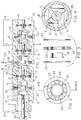
- Figure 1 is a partial cross section of two connected disconnectable mixing units and an end disconnectable mixing unit.
- Figure 2 is an end view of a bulkhead assembly.
- Figure 3 is an exploded cross section of the bulkhead assembly of Figure 2 at B-B'.
- Figure 4 is a cross section at A-A' of a disconnectable mixing unit showing the flywheel configuration.
- the dynamic in-line mixer of this invention is made up of disconnectable mixing units as shown by Figure 1 , a partial cross section of two connected disconnectable mixing units and an end disconnectable mixing unit where 2 illustrates one such unit.
- Each disconnectable mixing unit comprises a casing 6 containing a chamber 8 and a chamber wall 7 .
- the chamber is tubular in nature and its size is such that it can be connected with other disconnectable mixing units including an end disconnectable mixing unit 4 which varies from the other disconnectable mixing units in that it has a connection flange 5 for attachment to an inlet for one material to be mixed and a spindle driver 27 .
- each disconnectable mixing unit there is a spindle 12 which can be removably connected through male threaded spindle fasteners 13 to female threaded spindle fasteners 14 of another disconnectable mixing unit.
- Each disconnectable mixing unit has mixing means which are flywheels 10 . There are at least two flywheels per disconnectable mixing unit. Each flywheel is spaced from the next flywheel along the spindle to provide an area in which there is at least one mounted post 20 which protrudes into the chamber between the flywheels. There can be one or more such posts between each pair of flywheels. The posts 20 are mounted to protrude into chamber 8 from chamber wall 7 .
- each disconnectable mixing unit also contains a bulkhead assembly 15 . This bulkhead increases the mixing operation and provides a homogeneous product exiting material exit end 29 throughout the continuous operation of our in-line dynamic mixer.
- the bulkhead assembly 15 is shown in more detail from the end view in Figure 2 and from the exploded cross section in Figure 3 .
- the bulkhead assembly is made up of a bulkhead 23 which contains bulkhead perforations 24 .
- the number and size of perforations should be sufficient to allow the material to flow at an acceptable rate without being obstructive to the flow and without causing the shear to increase to an undesirable point.
- the bulkhead 23 is essentially stationary and is mounted such that a spindle bushing 16 is between bulkhead 23 and spindle 12 .
- the spindle bushing allows the spindle to rotate while the bulkhead remains stationary.
- the bulkhead 23 is held in place essentially perpendicular to the spindle axis by washers 22 .
- the flywheel 10 is illustrated in Figure 4 as the cross section at A-A' of a disconnectable mixing unit in Figure 1 .
- the flywheel has a folding recess 21 which can be the squared shape as shown or other shapes which can be curved instead of squared.
- This folding recess turns the material in a folding manner into the space between two flywheels where the post also cause a mixing action to take place.
- the spindle rotates, such as shown by 26 .
- the flywheels also rotate.
- At least one point on the flywheel at the longest radius from the spindle center describes a rotational circumference which is in spaced relationship with the chamber wall such that the material flows through the chamber without high shear and in a continuous manner.
- the shape of the flywheel and the nature of the folding recess facilitates the cleaning operations of the mixer.
- Our in-line dynamic mixer is especially useful for mixing a viscous material entering through the end disconnectable mixer unit and a low viscosity fluid material entering through an inlet port from a feed line in one of the disconnectable mixer units.
- This mixer is readily varied to allow for a plurality of disconnectable mixer units such that many kinds of materials can be added along the length of our in-line dynamic mixer.
- This mixer can be used to pigment products, to introduce additives and to add curing agents.
- a feature of this mixer is that it is useful for continuous operation in the production of homogeneous product exuding from the material exit end 29 .
Landscapes
- Chemical & Material Sciences (AREA)
- Chemical Kinetics & Catalysis (AREA)
- Mixers Of The Rotary Stirring Type (AREA)
- Processing And Handling Of Plastics And Other Materials For Molding In General (AREA)
Abstract
Description
- This invention relates to dynamic mixers which are useful for continuous mixing operations.
- Improved equipment for mixing materials of widely different viscosities to provide a homogeneous product is in demand. Today much of this equipment is either batch type equipment and/or static type mixers. Batch mixing equipment has the obvious disadvantage that it is slow, often leads to high waste rates and often expensive because of the labor costs. Static mixing equipment usually requires high shear conditions when highly viscous materials are mixed because the material is forced through the mixer and high shear can damage the material being mixed or increase the temperature above desirable ranges. Static mixers often require high pressures with the pressure differencial from input to output increasing with longer mixers or multiple mixers.
- A diligent search was conducted to find a mixer which would allow a continuous mixing operation and produce a product which was homogeneous over the entire process as long as the feeds were constant. We have now invented such a mixer.
- An object of this invention is to provide in-line mixer elements which rapidly move materials of different viscosities interchangeably from a dynamic inner rotating means to a stationary chamber (stator) wall with additional mixing provided by stationary posts and perforated plates (bulkheads).
- This invention introduces a mixing apparatus comprising a plurality of disconnectable mixing units, each said mixing unit having a casing with a chamber extending the length of said casing; a perforated bulkhead, removably disposed within the chamber of said casing, said perforated bulkhead having a spindle bushing disposed therein; and a spindle in coaxial relation to said chamber and rotatably mounted in said spindle bushing, said spindle having means for mixing and means for disconnectably coupling the spindle of an adjacent mixing unit, so that upon rotation of one spindle, the spindle in each mixing unit rotates and material within the chamber of each said mixing unit is mixed.
- Figure 1 is a partial cross section of two connected disconnectable mixing units and an end disconnectable mixing unit.
- Figure 2 is an end view of a bulkhead assembly.
- Figure 3 is an exploded cross section of the bulkhead assembly of Figure 2 at B-B'.
- Figure 4 is a cross section at A-A' of a disconnectable mixing unit showing the flywheel configuration.
-
- 2 - disconnectable mixing unit
- 4 - end disconnectable mixing unit
- 5 - connection flange
- 6 - casing
- 7 - chamber wall
- 8 - chamber
- 10 - flywheel
- 12 - spindle
- 13 - male threaded spindle fastener
- 14 - female threaded spindle fastener
- 15 - bulkhead assembly
- 16 - spindle bushing
- 18 - inlet port
- 20 - post
- 21 - folding recess
- 22 - washer
- 23 - bulkhead
- 24 - bulkhead perforation
- 25 - direction of material flow
- 26 - rotational direction of spindle
- 27 - spindle driver
- 28 - feed line
- 29 - material exit end
- The dynamic in-line mixer of this invention is made up of disconnectable mixing units as shown by Figure 1, a partial cross section of two connected disconnectable mixing units and an end disconnectable mixing unit where 2 illustrates one such unit. Each disconnectable mixing unit comprises a
casing 6 containing achamber 8 and achamber wall 7. The chamber is tubular in nature and its size is such that it can be connected with other disconnectable mixing units including an end disconnectable mixing unit 4 which varies from the other disconnectable mixing units in that it has a connection flange 5 for attachment to an inlet for one material to be mixed and aspindle driver 27. - In each disconnectable mixing unit, there is a
spindle 12 which can be removably connected through male threadedspindle fasteners 13 to female threadedspindle fasteners 14 of another disconnectable mixing unit. Each disconnectable mixing unit has mixing means which areflywheels 10. There are at least two flywheels per disconnectable mixing unit. Each flywheel is spaced from the next flywheel along the spindle to provide an area in which there is at least one mountedpost 20 which protrudes into the chamber between the flywheels. There can be one or more such posts between each pair of flywheels. Theposts 20 are mounted to protrude intochamber 8 fromchamber wall 7. For example, there may be four posts spaced approximately equidistance from each other around the casing and protruding into the chamber between a pair of flywheels. It is preferred to have at least four such posts between each pair of flywheels. Theseposts 20 may be attached to the casing by threaded means or may be welded into place or attached by whatever other means is suitable. Using posts which are attached by threaded means allows each post to potentially become a feed line for adding other materials. This allows flexibility by interchanging a post for a feed line with aninlet port 18 as illustrated in Figure 1. Each disconnectable mixing unit also contains abulkhead assembly 15. This bulkhead increases the mixing operation and provides a homogeneous product exitingmaterial exit end 29 throughout the continuous operation of our in-line dynamic mixer. - The
bulkhead assembly 15 is shown in more detail from the end view in Figure 2 and from the exploded cross section in Figure 3. The bulkhead assembly is made up of abulkhead 23 which containsbulkhead perforations 24. The number and size of perforations should be sufficient to allow the material to flow at an acceptable rate without being obstructive to the flow and without causing the shear to increase to an undesirable point. Thebulkhead 23 is essentially stationary and is mounted such that a spindle bushing 16 is betweenbulkhead 23 andspindle 12. The spindle bushing allows the spindle to rotate while the bulkhead remains stationary. Thebulkhead 23 is held in place essentially perpendicular to the spindle axis bywashers 22. - The
flywheel 10 is illustrated in Figure 4 as the cross section at A-A' of a disconnectable mixing unit in Figure 1. As shown, the flywheel has afolding recess 21 which can be the squared shape as shown or other shapes which can be curved instead of squared. This folding recess turns the material in a folding manner into the space between two flywheels where the post also cause a mixing action to take place. As the material flows through the chamber indirection 25, the spindle rotates, such as shown by 26. As the spindle rotates, the flywheels also rotate. At least one point on the flywheel at the longest radius from the spindle center, describes a rotational circumference which is in spaced relationship with the chamber wall such that the material flows through the chamber without high shear and in a continuous manner. The shape of the flywheel and the nature of the folding recess facilitates the cleaning operations of the mixer. - Our in-line dynamic mixer is especially useful for mixing a viscous material entering through the end disconnectable mixer unit and a low viscosity fluid material entering through an inlet port from a feed line in one of the disconnectable mixer units. This mixer is readily varied to allow for a plurality of disconnectable mixer units such that many kinds of materials can be added along the length of our in-line dynamic mixer. This mixer can be used to pigment products, to introduce additives and to add curing agents. A feature of this mixer is that it is useful for continuous operation in the production of homogeneous product exuding from the
material exit end 29.
Claims (4)
- A mixing apparatus comprising
a plurality of disconnectable mixing units (2), each said mixing unit (2) having
a casing (6) with a chamber (8) extending the length of said casing;
a perforated bulkhead (15, 23), removably disposed within the chamber (8) of said casing (6), said perforated bulkhead having a spindle bushing (16) disposed therein; and
a spindle (12) in coaxial relation to said chamber (8) and rotatably mounted in said spindle bushing (16), said spindle having means for mixing and means for disconnectably coupling the spindle of an adjacent mixing unit (2),
so that upon rotation of one spindle (12), the spindle in each mixing unit rotates and material within the chamber of each said mixing unit (2) is mixed. - The mixing apparatus in accordance with claim 1 wherein said means for mixing comprises at least two flywheels (10), each flywheel (10) having a substantially rounded configuration with folding recesses (21), said flywheels having a rotational circumference described by the longest flywheel radius which is in spaced relationship with the chamber wall (7).
- The mixing apparatus in accordance with claim 2 wherein said casing (6) has at least one post (20) mounted to protrude into said chamber (8) from said chamber wall (7).
- The mixing apparatus in accordance with claim 3 wherein at least one post (20) is replaced with an inlet port (18) extending to an outer region of said casing (6) to form a feed line (28).
Applications Claiming Priority (2)
| Application Number | Priority Date | Filing Date | Title |
|---|---|---|---|
| US184630 | 1994-01-21 | ||
| US08/184,630 US5350235A (en) | 1994-01-21 | 1994-01-21 | In line dynamic mixer with folding elements and perforated plates |
Publications (2)
| Publication Number | Publication Date |
|---|---|
| EP0664151A1 true EP0664151A1 (en) | 1995-07-26 |
| EP0664151B1 EP0664151B1 (en) | 1998-11-11 |
Family
ID=22677703
Family Applications (1)
| Application Number | Title | Priority Date | Filing Date |
|---|---|---|---|
| EP95300335A Expired - Lifetime EP0664151B1 (en) | 1994-01-21 | 1995-01-19 | In line dynamic mixer with folding elements and perforated plates |
Country Status (5)
| Country | Link |
|---|---|
| US (1) | US5350235A (en) |
| EP (1) | EP0664151B1 (en) |
| JP (1) | JP3578505B2 (en) |
| KR (1) | KR100348031B1 (en) |
| DE (1) | DE69505852T2 (en) |
Cited By (2)
| Publication number | Priority date | Publication date | Assignee | Title |
|---|---|---|---|---|
| WO1998019781A1 (en) * | 1996-11-01 | 1998-05-14 | E.I. Du Pont De Nemours And Company | Forming a solution of fluids having low miscibility and large-scale differences in viscosity |
| EP1151787A2 (en) * | 1996-11-01 | 2001-11-07 | E.I. Du Pont De Nemours & Company Incorporated | Forming a solution of fluids having low miscibility and large-scale differences in viscosity |
Families Citing this family (3)
| Publication number | Priority date | Publication date | Assignee | Title |
|---|---|---|---|---|
| KR200467983Y1 (en) * | 2011-10-28 | 2013-07-22 | 현남식 | Sterilizater auto pouring |
| US9149156B2 (en) | 2012-04-09 | 2015-10-06 | Sharkninja Operating Llc | Food processor |
| US20130264405A1 (en) | 2012-04-09 | 2013-10-10 | David M. Audette | Food processor |
Citations (3)
| Publication number | Priority date | Publication date | Assignee | Title |
|---|---|---|---|---|
| JPS5770628A (en) * | 1980-10-22 | 1982-05-01 | Asahi Chem Ind Co Ltd | Melt extrusion apparatus |
| US4640672A (en) * | 1983-11-26 | 1987-02-03 | Farrel Corporation | Modular extruder barrel construction |
| US5129729A (en) * | 1990-12-20 | 1992-07-14 | Paul Geyer | Extrusion apparatus for mixing and extruding of thermo-plastic and thermo-setting materials |
Family Cites Families (4)
| Publication number | Priority date | Publication date | Assignee | Title |
|---|---|---|---|---|
| US4260264A (en) * | 1979-05-21 | 1981-04-07 | The Japan Steel Works Ltd. | Biaxial vent extruder |
| DE2924462A1 (en) * | 1979-06-18 | 1981-01-22 | Josef A Blach | MATERIAL PROCESSING SHAFT FOR MACHINES FOR THE PROCESSING OF SOLID, LIQUID, PLASTIC AND / OR TOOTH-VISCOSE MATERIALS |
| JPH0742392B2 (en) * | 1986-01-07 | 1995-05-10 | 東芝機械株式会社 | ABS resin manufacturing method and apparatus |
| JPH0729294B2 (en) * | 1986-08-13 | 1995-04-05 | 株式会社ブリヂストン | Rubber-like material kneading device |
-
1994
- 1994-01-21 US US08/184,630 patent/US5350235A/en not_active Expired - Lifetime
-
1995
- 1995-01-19 EP EP95300335A patent/EP0664151B1/en not_active Expired - Lifetime
- 1995-01-19 DE DE69505852T patent/DE69505852T2/en not_active Expired - Lifetime
- 1995-01-20 JP JP00679395A patent/JP3578505B2/en not_active Expired - Lifetime
- 1995-01-20 KR KR1019950000896A patent/KR100348031B1/en not_active IP Right Cessation
Patent Citations (3)
| Publication number | Priority date | Publication date | Assignee | Title |
|---|---|---|---|---|
| JPS5770628A (en) * | 1980-10-22 | 1982-05-01 | Asahi Chem Ind Co Ltd | Melt extrusion apparatus |
| US4640672A (en) * | 1983-11-26 | 1987-02-03 | Farrel Corporation | Modular extruder barrel construction |
| US5129729A (en) * | 1990-12-20 | 1992-07-14 | Paul Geyer | Extrusion apparatus for mixing and extruding of thermo-plastic and thermo-setting materials |
Non-Patent Citations (1)
| Title |
|---|
| DATABASE WPI Week 8223, Derwent World Patents Index; AN 82-47048E * |
Cited By (4)
| Publication number | Priority date | Publication date | Assignee | Title |
|---|---|---|---|---|
| WO1998019781A1 (en) * | 1996-11-01 | 1998-05-14 | E.I. Du Pont De Nemours And Company | Forming a solution of fluids having low miscibility and large-scale differences in viscosity |
| US6179458B1 (en) | 1996-11-01 | 2001-01-30 | E. I. Du Pont De Nemours And Company | Forming a solution of fluids having low miscibility and large-scale differences in viscosity |
| EP1151787A2 (en) * | 1996-11-01 | 2001-11-07 | E.I. Du Pont De Nemours & Company Incorporated | Forming a solution of fluids having low miscibility and large-scale differences in viscosity |
| EP1151787A3 (en) * | 1996-11-01 | 2002-01-30 | E.I. Du Pont De Nemours & Company Incorporated | Forming a solution of fluids having low miscibility and large-scale differences in viscosity |
Also Published As
| Publication number | Publication date |
|---|---|
| DE69505852T2 (en) | 1999-07-08 |
| DE69505852D1 (en) | 1998-12-17 |
| EP0664151B1 (en) | 1998-11-11 |
| US5350235A (en) | 1994-09-27 |
| KR950031199A (en) | 1995-12-18 |
| KR100348031B1 (en) | 2002-10-25 |
| JP3578505B2 (en) | 2004-10-20 |
| JPH0833837A (en) | 1996-02-06 |
Similar Documents
| Publication | Publication Date | Title |
|---|---|---|
| DE4106998C2 (en) | Mixing device | |
| EP1771241B1 (en) | Dynamic mixer and its use | |
| DE60120738T2 (en) | DYNAMIC MIXER | |
| EP2566609B1 (en) | Emulsification device for continuously producing emulsions and/or dispersions | |
| WO2007065572A2 (en) | Large-scale reactor or thin-film evaporator with premixing unit | |
| US3559956A (en) | Planetary gear mixer | |
| EP0178830B1 (en) | Continuous mixer | |
| US5350235A (en) | In line dynamic mixer with folding elements and perforated plates | |
| DE2809228C2 (en) | ||
| EP1474223B1 (en) | Dynamic mixer | |
| US4482254A (en) | Fluid mixing apparatus and method | |
| US4099268A (en) | Mixing device | |
| US5738439A (en) | Mixing apparatus | |
| US4334788A (en) | Pin action mixing pump | |
| WO2000012788A1 (en) | Device for mixing and transporting a polymer melt | |
| EP0669193A1 (en) | A glue mixing device | |
| EP0158358A2 (en) | Device for dispersing and/or emulsification of a mixture consisting of at least two materials | |
| DE10012072B4 (en) | Inline mixer | |
| DE3919828C2 (en) | Loop reactor | |
| US2972168A (en) | Mixing and thickening machine for extrusion | |
| US3679141A (en) | Grinding apparatus | |
| US3499633A (en) | Mixing device | |
| EP0475015A1 (en) | Method and apparatus for continuously grinding and dispersing solids in fluids | |
| DE3319921A1 (en) | Process and equipment for preparing finely divided dispersions | |
| SU1685255A3 (en) | Continuous mixer for viscous liquids |
Legal Events
| Date | Code | Title | Description |
|---|---|---|---|
| PUAI | Public reference made under article 153(3) epc to a published international application that has entered the european phase |
Free format text: ORIGINAL CODE: 0009012 |
|
| AK | Designated contracting states |
Kind code of ref document: A1 Designated state(s): DE FR GB IT |
|
| 17P | Request for examination filed |
Effective date: 19950824 |
|
| 17Q | First examination report despatched |
Effective date: 19970225 |
|
| GRAG | Despatch of communication of intention to grant |
Free format text: ORIGINAL CODE: EPIDOS AGRA |
|
| GRAG | Despatch of communication of intention to grant |
Free format text: ORIGINAL CODE: EPIDOS AGRA |
|
| GRAH | Despatch of communication of intention to grant a patent |
Free format text: ORIGINAL CODE: EPIDOS IGRA |
|
| GRAH | Despatch of communication of intention to grant a patent |
Free format text: ORIGINAL CODE: EPIDOS IGRA |
|
| GRAA | (expected) grant |
Free format text: ORIGINAL CODE: 0009210 |
|
| AK | Designated contracting states |
Kind code of ref document: B1 Designated state(s): DE FR GB IT |
|
| REF | Corresponds to: |
Ref document number: 69505852 Country of ref document: DE Date of ref document: 19981217 |
|
| ITF | It: translation for a ep patent filed |
Owner name: UFFICIO BREVETTI RAPISARDI S.R.L. |
|
| ET | Fr: translation filed | ||
| PLBE | No opposition filed within time limit |
Free format text: ORIGINAL CODE: 0009261 |
|
| STAA | Information on the status of an ep patent application or granted ep patent |
Free format text: STATUS: NO OPPOSITION FILED WITHIN TIME LIMIT |
|
| 26N | No opposition filed | ||
| REG | Reference to a national code |
Ref country code: GB Ref legal event code: IF02 |
|
| REG | Reference to a national code |
Ref country code: DE Ref legal event code: R082 Ref document number: 69505852 Country of ref document: DE Representative=s name: FLEISCHER, ENGELS & PARTNER MBB, PATENTANWAELT, DE |
|
| PGFP | Annual fee paid to national office [announced via postgrant information from national office to epo] |
Ref country code: DE Payment date: 20140115 Year of fee payment: 20 |
|
| PGFP | Annual fee paid to national office [announced via postgrant information from national office to epo] |
Ref country code: FR Payment date: 20140108 Year of fee payment: 20 Ref country code: IT Payment date: 20140120 Year of fee payment: 20 |
|
| PGFP | Annual fee paid to national office [announced via postgrant information from national office to epo] |
Ref country code: GB Payment date: 20140115 Year of fee payment: 20 |
|
| REG | Reference to a national code |
Ref country code: DE Ref legal event code: R071 Ref document number: 69505852 Country of ref document: DE |
|
| REG | Reference to a national code |
Ref country code: GB Ref legal event code: PE20 Expiry date: 20150118 |
|
| PG25 | Lapsed in a contracting state [announced via postgrant information from national office to epo] |
Ref country code: GB Free format text: LAPSE BECAUSE OF EXPIRATION OF PROTECTION Effective date: 20150118 |