EP0663649B1 - Dispositif de connexion au format PCMCIA - Google Patents
Dispositif de connexion au format PCMCIA Download PDFInfo
- Publication number
- EP0663649B1 EP0663649B1 EP95300015A EP95300015A EP0663649B1 EP 0663649 B1 EP0663649 B1 EP 0663649B1 EP 95300015 A EP95300015 A EP 95300015A EP 95300015 A EP95300015 A EP 95300015A EP 0663649 B1 EP0663649 B1 EP 0663649B1
- Authority
- EP
- European Patent Office
- Prior art keywords
- chariot
- connection device
- card
- memory card
- connector
- Prior art date
- Legal status (The legal status is an assumption and is not a legal conclusion. Google has not performed a legal analysis and makes no representation as to the accuracy of the status listed.)
- Expired - Lifetime
Links
Images


Classifications
-
- G—PHYSICS
- G06—COMPUTING; CALCULATING OR COUNTING
- G06F—ELECTRIC DIGITAL DATA PROCESSING
- G06F12/00—Accessing, addressing or allocating within memory systems or architectures
-
- G—PHYSICS
- G06—COMPUTING; CALCULATING OR COUNTING
- G06K—GRAPHICAL DATA READING; PRESENTATION OF DATA; RECORD CARRIERS; HANDLING RECORD CARRIERS
- G06K13/00—Conveying record carriers from one station to another, e.g. from stack to punching mechanism
- G06K13/02—Conveying record carriers from one station to another, e.g. from stack to punching mechanism the record carrier having longitudinal dimension comparable with transverse dimension, e.g. punched card
- G06K13/08—Feeding or discharging cards
Definitions
- This invention relates to a connection device for making electrical connection between a memory card and an electronic apparatus such as a computer, the device having a mechanism for drawing the memory card into the apparatus when in use.
- Memory cards are electronic components usually comprising a substrate card with electronic chips and circuitry thereon, the memory card being pluggable to a computer and acting as a module for storing programs, providing memory space, releasing the identity of the user, and other such applications.
- the increasing compactness of electronic components and assembly thereof has led to increasing the number of applications and therefore the use of memory cards.
- certain standards have been developed, for example the PCMCIA (Personal Computer Memory Card International Association) standard that defines, inter alia, the connection interface and external dimensions of the cards. To this date, there are three standard PCMCIA cards, type 1, type 2 and type 3.
- EP-A-232 115 describes a device for reading and writing data stored on a magnetic and/or integrated circuit card as external memory.
- the device comprises a casing which is formed with a slot in one end wall thereof for manual insertion of a card, whereupon a drive mechanism operates to convey the partly inserted card into contact with a connector block for reading/writing.
- connection device for connecting a PCMCIA memory card to an electronic apparatus that draws the card into the apparatus such that it is protected by the faraday cage thereof for eliminating electromagnetic and electrostatic interference therewith.
- the invention consists in a PCMCIA memory card connection device for receiving a memory card in an electronic apparatus for electrical connection therewith, comprising a memory card support frame and a chariot slidably mounted in the support frame, characterised in that the chariot has a memory card connector for electrical connection with the memory card, and an electrical motor mechanism for moving the chariot, and the memory card connector includes pin terminals for electrical connection with receptacle contacts of the memory card and is arranged so that the card can be fully mated with the connector by manual insertion of the card into the device, whereupon the motor mechanism is operable to move the card from a first position in which it projects from the electronic apparatus, where fully mated with the connector, to a second position within the apparatus.
- connection device may also be provided with a second chariot slidably received in the support frame for connection to a plurality of standardized card, e.g. simultaneous connection to PCMCIA type 1 and type 2, or connection to PCMCIA type 3.
- a single memory card connection device 2 comprises a support frame 4 within which is mounted a slidable chariot 6 for receiving a first memory card 8 within an electronic apparatus having a printed circuit board 10 and an outer electrically conductive shell 12.
- the memory card connection device 2 is mounted on the printed circuit board 10 and electrically connected thereto via a flat flexible cable 14 folded over in a U-bend 15.
- the memory card connection device 2 further comprises a motor mechanism 16 for slidably moving the chariot 6 within the support frame 4, the motor mechanism 16 comprising an electrical motor 18 mounted to the support frame 4, and a worm gear 20 engaged in a thread 22 in a lateral guide 24 of the chariot 6.
- the support frame 4 comprises side walls 26 for laterally guiding the chariot 6, whereby lateral guides 24 and 28 of the chariot 6 are contiguous the respective side walls 26 of the frame 4.
- a transverse bar 30 Joining the lateral guides 24, 28, is a transverse bar 30 to which a memory card connector 32 is mounted, the connector 32 having pin terminals therein for connection with receptacle contacts of the card 8, the pin terminals being also interconnected with the flat flexible cable 14.
- a front edge 36 of the printed circuit board 10 is spaced from the electronic apparatus outer shell 12 and card guides 38 are positioned therebetween on either side of the card 8 for accurate guiding thereof into the connection device 2.
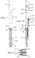
- the card 8 as shown in Figures 1-4 has electronic circuitry therein and is standardized according to the PCMCIA type 3 standard which defines the connection interface and exterior dimensions of the card 8.
- the thickness of the type 3 card is approximately 10.5 mm and there are other standard PCMCIA cards according to type 1 and type 2 standards which relate to the cards 8' and 8'' shown in Figure 6 and have thicknesses of 3.3mm and 5mm respectively, the sum of which is slightly less than the thickness of the type 3 card.
- the cards of type 1, 2 and 3 have lateral guide protrusions 48 respectively which are disposed in the same positions with respect to receptacle connectors 50, 52, 54 respectively thereof. The latter means that if a connector is matable with a type 3 card, it will also be matable with a type 1 or a type 2 card.
- the chariot 6 is shown in a forwardmost position whereby the lateral guides 24, 28 abut a front wall 60 of the support frame 4, the front wall 60 having an opening 62 for receiving the card type 3 therethrough between the lateral guides 24, 28 which have lateral grooves 64 therein engageable around the guide protrusion 48 of the card.
- the chariot 6 and a housing 66 of the connector 32 for receiving the pin terminals therein, can be integrally moulded with the chariot 6 for reducing the number of parts. The latter solution would provide a cost-effective design.
- the chariot 6 abuts the front wall 60 of the support frame 4 as shown in Figure 1.
- the memory card 8 can then be inserted through the outer wall 12 of the electronic apparatus, laterally guided by the guides 38 that also ensure that the card 8 is correctly orientated by cooperation with the lateral protrusions 48.
- Manual insertion of the card 8 is continued until the connector 50 of the card is fully mated with the connector 32 of the connection device 2. This requires a considerable force in comparison to inserting and sliding forces of the card 8 which is only opposed by frictional forces of the cooperating guides.
- the gear acts as a stop member due to the irreversibility hereof, holding the chariot in it's forward position.
- electronic circuitry of the computer detects full insertion due to a micro switch 72 fixed to the transverse bar 30 of the chariot and being engageable against the card.
- Indication of full insertion starts the motor 18 which pulls the chariot 6 into a rearmost position proximate a rear wall of the support frame whereby the card 8 is withdrawn well into the electronic apparatus, at a sufficient distance from the external conductive surface 12 to be uninfluenced by the card receiving hole therein and subject to the full effect of the faraday cage for protecting the memory card from external electromagnetic noise. Additionally, as the card 8 is well retracted into the machine, it is much less prone to damage during transport or otherwise.
- the worm gear 20 has the advantage of reducing the torque of the electrical motor required to draw back the carriage 6, and a very small motor 18 can therefore be used which helps to maintain the design very compact.
- Initial manual insertion of the card 8 also keeps the motor size very small as a much larger motor would be needed to overcome the mating forces between the card and the connection device 2, whereby some sort of gripping means on the card would also be necessary, which are however not provided for in the PCMCIA standard.
- Full insertion of the card into the machine by an electrical motor also means that the motor is actuated to push out the card, whereby this can be electronically controlled to ensure that no inadvertent extraction of the card is effectuated without necessary steps being taken, e.g. closing files or programs related thereto.
- the flat flexible cable 14 is bent over in a U-shape extension which allows the cable to roll backwards and forwards about the U-bend 15 during movement of the chariot 6.
- the cable 14 is relatively rigid in its plane, thereby not needing lateral guiding other than connection to the connectors at either end.
- FIG. 5-8 another embodiment 2' is shown comprising two chariots 6', 6'' for connection to, for example, PCMCIA memory cards 8', 8" of type 1 and type 2 respectively, whereby the chariots 6' and 6'' are mountable one above the other and are similar in construction to the chariots 6 of the embodiment of Figures 1-4.
- connectors 32', 32'' of the chariots 6', 6'' which have a lower profile than the embodiment of Figures 1-4.
- Both chariots 6' and 6'' are driven by separate motors 18', 18'' which are mounted proximate opposing side walls 26', 27' of the support frame 4'.
- connection device 2' is likewise mounted on a printed circuit board 10' and connection thereto is made via flat flexible cables 14', 14'' interconnecting the memory cards 8', 8'' to respective connectors 70', 70'' mounted on the printed circuit board 10'.
- the first and second cards 8', 8'' can be individually loaded or extracted from the electronic apparatus as desired.
- Full insertion of type 1 and type 2 cards 8', 8'' is detected by microswitches 72', 72'' respectively positioned in the connectors 70', 70''.
- a further microswitch 73''' is positioned on top of the lower chariot 6', between the chariots 6' and 6'', for detecting connection of a type 3 card 8.
- the PCMCIA type 3 card 8 could also be inserted into this embodiment 2' whereby the guide protrusions 48 of the type 3 card are in the same position as the guide protrusions of the PCMCIA type 1 card 8' in relation to the card receptacle connector portions 50, 50', the type 3 card 8 therefore being connectable to the lower chariot 6'.
- the electronic command of the motors 18', 18'' would recognize that a type 3 card is inserted, e.g. because both micro switches 72', 72''' of the first chariot 6' would be actuated, thereby commanding the withdrawal of both chariots 6', 6'' in order to allow insertion of the type 3 card into the connection device 2'.
- Positioning of the motors 18', 18'' on substantially the same level does not substantially increase the space requirements of the connection device 2' and is therefore a compact design.
- the embodiment of Figures 6-8 therefore advantageously allows connection of memory cards according to either the type 3 PCMCIA standard or the simultaneously type 1 and type 2 PCMCIA standards.
- the memory cards can be drawn fully into the faraday cage of a computer for protection thereof and in particular for protection against electromagnetic and electrostatic interference from the exterior of the computing device.
- the long chariot guides provide stable guiding of the sliding chariot within the support frame, whereby a connector is advantageously mounted thereto, providing electrical connection to the memory cards without waiting for full insertion thereof into the connection device.
- the latter additionally avoids having a large electrical motor to drive the chariot as the contact forces do not have to be overcome thereby, but only the frictional forces of the sliding chariot.
- the connector housing can also be integrally moulded with the chariot for a compact and cost-effective design. Use of the worm gear to drive the chariot, provides also a stop function to hold the chariot in position due to the irreversibility of the worm gear.
- the connection device as described hereinabove is therefore compact, has few parts and is cost-effective yet reliable.
Landscapes
- Engineering & Computer Science (AREA)
- Theoretical Computer Science (AREA)
- Physics & Mathematics (AREA)
- General Physics & Mathematics (AREA)
- General Engineering & Computer Science (AREA)
- Coupling Device And Connection With Printed Circuit (AREA)
- Details Of Connecting Devices For Male And Female Coupling (AREA)
Claims (16)
- Dispositif de connexion (2) pour carte mémoire PCMCIA destiné à recevoir une carte mémoire (8, 8', 8") dans un appareil électronique en vue d'une connexion électrique avec celui-ci, comprenant un châssis de support (4, 4') de carte mémoire et un chariot (6, 6', 6") monté coulissant dans le châssis de support, caractérisé en ce que le chariot possède un connecteur (32, 32', 32") pour carte mémoire en vue d'une connexion électrique avec la carte mémoire, et un mécanisme à moteur électrique (18, 18') pour déplacer le chariot, et le connecteur (32, 32', 32") pour carte mémoire comporte des bornes à broches en vue d'une connexion électrique avec des contacts à alvéoles de la carte mémoire (8, 8', 8") et est agencé de façon à ce que la carte puisse être emboítée à fond avec le connecteur par insertion manuelle de la carte dans le dispositif, sur quoi le mécanisme à moteur peut être actionné pour déplacer la carte d'une première position dans laquelle elle fait saillie depuis l'appareil électronique, où elle est emboítée à fond avec le connecteur, à une deuxième position à l'intérieur de l'appareil.
- Dispositif de connexion selon la revendication 1, dans lequel le chariot coulissant (6, 6') comprend des barres de guidage latérales (24, 28, 24', 28') et une barre transversale (30, 30') se prolongeant entre celles-ci, les barres de guidage (24, 28, 24', 28') pouvant coopérer avec le châssis de support (4, 4') pour guider le chariot (6, 6').
- Dispositif de connexion selon la revendication 2, dans lequel les barres de guidage latérales (24, 28, 24', 28') sont parallèles l'une à l'autre et essentiellement perpendiculaires à la barre transversale (30).
- Dispositif de connexion selon la revendication 2 ou 3, dans lequel le connecteur (32, 32') est monté sur la barre transversale (30, 30').
- Dispositif de connexion selon la revendication 2, 3 ou 4, dans lequel les barres de guidage latérales (24, 28, 24', 28') sont espacées de façon à pouvoir recevoir entre elles la carte (8, 8').
- Dispositif de connexion selon l'une quelconque des revendications précédentes, dans lequel le mécanisme à moteur électrique (16, 16') comprend un engrenage à vis sans fin (20, 20') pour faire coulisser le chariot (6, 6').
- Dispositif de connexion selon la revendication 6, dans lequel l'engrenage à vis sans fin (20, 20') engrène un filetage complémentaire (22, 22') dans l'une des barres de guidage latérales (24, 24') du chariot (6, 6').
- Dispositif de connexion selon l'une quelconque des revendications précédentes, dans lequel le mécanisme à moteur comprend un moteur électrique (18, 18') monté sur le châssis de support (4, 4').
- Dispositif de connexion selon l'une quelconque des revendications précédentes, dans lequel le chariot (6, 6') est guidé par des parois latérales extérieures (26, 27, 26', 27') du châssis de support (4, 4').
- Dispositif de connexion selon l'une quelconque des revendications précédentes, dans lequel le mécanisme à moteur (16, 16') est disposé essentiellement en ligne avec l'une des barres de guidage latérales (24, 24') du chariot (6, 6').
- Dispositif de connexion selon l'une quelconque des revendications précédentes, dans lequel le connecteur (32, 32') est connecté à un câble conducteur souple plat (14, 14') pouvant être plié pour former un U (15, 15') pour permettre le mouvement du chariot (6, 6').
- Dispositif de connexion selon l'une quelconque des revendications précédentes, dans lequel le châssis de support (4, 4') peut être monté sur une carte à circuit imprimé (10, 10') de l'appareil électronique.
- Dispositif de connexion selon l'une quelconque des revendications précédentes, dans lequel le chariot (6, 6') est moulé d'une pièce sur un boítier (66, 66') du connecteur (32, 32').
- Dispositif de connexion selon l'une quelconque des revendications précédentes, comportant un deuxième chariot coulissant (6") monté au-dessus du chariot (6') mentionné en premier et fonctionnant d'une manière similaire à celui-ci pour recevoir une deuxième carte mémoire (8").
- Dispositif de connexion selon la revendication 14, dans lequel le deuxième chariot (6") peut être déplacé par un deuxième mécanisme à moteur électrique (16") similaire au mécanisme à moteur électrique (16') mentionné en premier, les premier et deuxième mécanismes à moteur (16', 16") étant montés à proximité de côtés opposés (26', 27') du châssis de support (4').
- Dispositif de connexion selon l'une quelconque des revendications précédentes, dans lequel un commutateur (72, 72', 72", 72'") est monté sur le ou chaque chariot (6, 6', 6") pour détecter la fin de l'emboítement de la carte mémoire (8, 8', 8") au connecteur (32, 32', 32") pour carte mémoire du chariot.
Applications Claiming Priority (2)
| Application Number | Priority Date | Filing Date | Title |
|---|---|---|---|
| FR9400328 | 1994-01-13 | ||
| FR9400328A FR2714989A1 (fr) | 1994-01-13 | 1994-01-13 | Dispositif de connexion de carte à mémoire. |
Publications (2)
| Publication Number | Publication Date |
|---|---|
| EP0663649A1 EP0663649A1 (fr) | 1995-07-19 |
| EP0663649B1 true EP0663649B1 (fr) | 2000-03-08 |
Family
ID=9459008
Family Applications (1)
| Application Number | Title | Priority Date | Filing Date |
|---|---|---|---|
| EP95300015A Expired - Lifetime EP0663649B1 (fr) | 1994-01-13 | 1995-01-03 | Dispositif de connexion au format PCMCIA |
Country Status (7)
| Country | Link |
|---|---|
| US (1) | US5637001A (fr) |
| EP (1) | EP0663649B1 (fr) |
| JP (1) | JPH07220804A (fr) |
| KR (1) | KR950033831A (fr) |
| DE (1) | DE69515350T2 (fr) |
| FR (1) | FR2714989A1 (fr) |
| TW (1) | TW268128B (fr) |
Families Citing this family (16)
| Publication number | Priority date | Publication date | Assignee | Title |
|---|---|---|---|---|
| KR19980015695A (ko) * | 1996-08-23 | 1998-05-25 | 김광호 | 비엔씨 컨넥터의 사용이 가능한 피씨엠씨아이에이 카드 |
| WO1998048376A1 (fr) * | 1997-04-21 | 1998-10-29 | The Whitaker Corporation | Appareil ejecteur pour connecteur de carte a memoire |
| US7014118B1 (en) | 1997-10-10 | 2006-03-21 | Robinson Nugent, Inc | Module header apparatus |
| US6067234A (en) * | 1997-12-22 | 2000-05-23 | International Business Machines Corporation | Adaptor connection apparatus for a data processing system |
| KR20000009441A (ko) * | 1998-07-24 | 2000-02-15 | 구자홍 | 외부 메모리 카드 착탈에 따른 오동작 방지 장치 |
| GB9904839D0 (en) * | 1999-03-03 | 1999-04-28 | Psion Computers Plc | Apparatus for retaining a computer card |
| US6345988B1 (en) * | 1999-03-12 | 2002-02-12 | 3Com Corporation | Inter-card connection between adjacently positioned expansion cards |
| JP4240706B2 (ja) * | 1999-08-23 | 2009-03-18 | ソニー株式会社 | 記憶媒体のローディング装置 |
| US20080278903A1 (en) * | 2000-01-06 | 2008-11-13 | Super Talent Electronics, Inc. | Package and Manufacturing Method for Multi-Level Cell Multi-Media Card |
| US6498730B2 (en) * | 2000-12-13 | 2002-12-24 | International Business Machines Corporation | Apparatus and method for inserting, retaining and extracting printed circuit boards |
| US6577500B2 (en) | 2001-02-28 | 2003-06-10 | 3Com Corporation | Wireless PC card |
| US6461170B1 (en) | 2001-05-17 | 2002-10-08 | 3Com Corporation | Stacked electronic integrated card assembly with multi-function shared interface |
| US6782442B2 (en) * | 2001-06-15 | 2004-08-24 | Sun Microsystems, Inc. | CompactPCI hotswap automatic insertion/extraction test equipment |
| US11751362B2 (en) | 2021-10-22 | 2023-09-05 | International Business Machines Corporation | Thermally activated retractable EMC protection |
| US11695240B2 (en) | 2021-10-22 | 2023-07-04 | International Business Machines Corporation | Retractable EMC protection |
| US11871550B2 (en) | 2021-10-22 | 2024-01-09 | International Business Machines Corporation | Motor controlled retractable EMC protection |
Family Cites Families (31)
| Publication number | Priority date | Publication date | Assignee | Title |
|---|---|---|---|---|
| US4128288A (en) * | 1977-05-27 | 1978-12-05 | Burroughs Corporation | Zero insertion/retraction force connector |
| GB2054506A (en) * | 1979-07-30 | 1981-02-18 | Omex | Magnetic transport mechanism |
| DE3221445C2 (de) * | 1982-01-05 | 1985-03-14 | Dicom Electronics GmbH, 5000 Köln | Kartenlesegerät |
| DE3412453A1 (de) * | 1984-04-03 | 1985-10-10 | Siemens AG, 1000 Berlin und 8000 München | Kontaktiereinrichtung fuer eine mit einem integrierten halbleiterschaltkreis versehene steckkarte |
| US4724310A (en) * | 1984-07-02 | 1988-02-09 | Tokyo Tatsuno Co., Ltd. | Device for inserting and holding an IC card as an external memory during reading and writing operations |
| CA1281815C (fr) * | 1986-01-16 | 1991-03-19 | Shunzo Takahashi | Appareil de lecture-ecriture pour carte a memoire optique |
| JPS62179084A (ja) * | 1986-01-31 | 1987-08-06 | Tokyo Tatsuno Co Ltd | 板状記憶媒体の読取り・書込み装置 |
| DE8631861U1 (fr) * | 1986-11-28 | 1987-02-05 | Siemens Ag, 1000 Berlin Und 8000 Muenchen, De | |
| JPH0541511Y2 (fr) * | 1987-05-18 | 1993-10-20 | ||
| JPS63316289A (ja) * | 1987-06-19 | 1988-12-23 | Diesel Kiki Co Ltd | Icカ−ド読み取り・書き込み装置 |
| US4839509A (en) * | 1987-06-19 | 1989-06-13 | Diesel Kiki Co., Ltd. | Connector device for connecting IC card to reading and/or writing apparatus |
| US4887188A (en) * | 1987-12-22 | 1989-12-12 | Casio Computer Co., Ltd. | Connector for a memory card |
| JPH0541509Y2 (fr) * | 1988-03-03 | 1993-10-20 | ||
| JP2628346B2 (ja) * | 1988-07-01 | 1997-07-09 | 株式会社トプコン | メモリカード格納装置 |
| JPH0517826Y2 (fr) * | 1988-07-29 | 1993-05-12 | ||
| US5146069A (en) * | 1988-09-19 | 1992-09-08 | Fuji Photo Film Co., Ltd. | Device for loading and unloading a memory cartridge using a sliding member |
| JPH0733402Y2 (ja) * | 1989-03-01 | 1995-07-31 | コネクタ装置 | |
| US4936790A (en) * | 1989-04-28 | 1990-06-26 | Apple Computer, Inc. | Low insertion force connector |
| WO1991000681A1 (fr) * | 1989-06-30 | 1991-01-10 | Poqet Computer Corporation | Plateau d'introduction de carte memoire pour ordinateur portatif |
| US5026296A (en) * | 1990-03-05 | 1991-06-25 | Japan Aviation Electronics Industry, Limited | Electrical connector equipped with release mechanism |
| JPH03297084A (ja) * | 1990-04-17 | 1991-12-27 | I T T Canon:Kk | エジェクタ付カードコネクタ |
| JPH0737159Y2 (ja) * | 1990-04-26 | 1995-08-23 | ホシデン株式会社 | メモリカードコネクタ |
| JP2521376Y2 (ja) * | 1990-08-31 | 1996-12-25 | デュポン アジア パシフィック リミテッド | Icパック用コネクタ装置 |
| DE4029576C2 (de) * | 1990-09-18 | 1994-12-01 | Amphenol Tuchel Elect | Kontaktiereinrichtung für Standard-Chipkarte und SIM-Karte |
| US5179505A (en) * | 1990-09-28 | 1993-01-12 | Fuji Photo Film Co., Ltd. | Ejector for memory card |
| US5161989A (en) * | 1990-11-30 | 1992-11-10 | Itt Corporation | Ejector equipped card connector |
| US5139435A (en) * | 1990-12-04 | 1992-08-18 | Hosiden Corporation | Multipolar electrical connector |
| US5197894A (en) * | 1991-05-30 | 1993-03-30 | Japan Aviation Electronics Industry, Limited | Electrical connector equipped with a release mechanism |
| US5149276A (en) * | 1991-12-18 | 1992-09-22 | Amp Incorporated | Modular holder having an ejector mechanism for a dual IC package |
| JPH05233886A (ja) * | 1992-02-25 | 1993-09-10 | Hitachi Ltd | カード取扱装置 |
| US5234351A (en) * | 1992-12-07 | 1993-08-10 | The Whitaker Corporation | Memory card holder and ejection mechanism |
-
1994
- 1994-01-13 FR FR9400328A patent/FR2714989A1/fr not_active Withdrawn
- 1994-04-21 TW TW083103531A patent/TW268128B/zh active
-
1995
- 1995-01-03 DE DE69515350T patent/DE69515350T2/de not_active Expired - Fee Related
- 1995-01-03 EP EP95300015A patent/EP0663649B1/fr not_active Expired - Lifetime
- 1995-01-05 KR KR1019950000060A patent/KR950033831A/ko not_active Application Discontinuation
- 1995-01-09 US US08/370,135 patent/US5637001A/en not_active Expired - Fee Related
- 1995-01-13 JP JP7020941A patent/JPH07220804A/ja active Pending
Also Published As
| Publication number | Publication date |
|---|---|
| DE69515350D1 (de) | 2000-04-13 |
| US5637001A (en) | 1997-06-10 |
| JPH07220804A (ja) | 1995-08-18 |
| EP0663649A1 (fr) | 1995-07-19 |
| DE69515350T2 (de) | 2000-08-24 |
| TW268128B (fr) | 1996-01-11 |
| FR2714989A1 (fr) | 1995-07-13 |
| KR950033831A (ko) | 1995-12-26 |
Similar Documents
| Publication | Publication Date | Title |
|---|---|---|
| EP0663649B1 (fr) | Dispositif de connexion au format PCMCIA | |
| US6129572A (en) | Electrical connector with latch to retain IC card | |
| US5548484A (en) | IC card-receiving host | |
| US6219231B1 (en) | Card-shaped storage medium and information processing apparatus having guide portion for the same | |
| US5511986A (en) | IC pack connector with detect switch | |
| EP0293215B1 (fr) | Mécanisme sur le guide d'une carte pour l'insertion et l'extraction | |
| EP0627785B1 (fr) | Dispositif de connexion pour boîtiers de IC | |
| EP0624934B1 (fr) | Appareil de connexion pour cartes de circuits intégrés avec interrupteur | |
| US7410375B2 (en) | Card connector with ejecting mechanism | |
| EP0880106B1 (fr) | Verrouillage pour adaptateur de carte à puce | |
| EP0057329A1 (fr) | Arrangement de connexion électrique | |
| US6550684B1 (en) | Chip card ejector system | |
| US6767232B1 (en) | Electrical card connector having write-protect and full-insertion switches | |
| US6839431B2 (en) | Card connector | |
| CN100511270C (zh) | 带有卡弹出机构的存储卡连接器 | |
| WO2012075014A2 (fr) | Connecteur de carte | |
| US20100227489A1 (en) | Electrical card connector | |
| US20040092146A1 (en) | Electrical card connector having card retention mechanism integrally formed with an ejector | |
| US4936790A (en) | Low insertion force connector | |
| WO2001089041A1 (fr) | Connecteur de cartes à circuit imprimé a verrouillage de cartes | |
| KR100344504B1 (ko) | 로킹수단을구비한정보처리매체커넥터 | |
| US8246366B2 (en) | Electrical card connector with a stop member for temporarily preventing a card from ejecting from the card release position | |
| US7628625B2 (en) | Card connector | |
| US7534119B2 (en) | Stacked card connector having ejecting mechanism | |
| CN100458821C (zh) | 用于存储卡连接器上容纳不同尺寸存储卡的适配器 |
Legal Events
| Date | Code | Title | Description |
|---|---|---|---|
| PUAI | Public reference made under article 153(3) epc to a published international application that has entered the european phase |
Free format text: ORIGINAL CODE: 0009012 |
|
| AK | Designated contracting states |
Kind code of ref document: A1 Designated state(s): DE FR GB |
|
| 17P | Request for examination filed |
Effective date: 19950814 |
|
| 17Q | First examination report despatched |
Effective date: 19980605 |
|
| GRAG | Despatch of communication of intention to grant |
Free format text: ORIGINAL CODE: EPIDOS AGRA |
|
| GRAG | Despatch of communication of intention to grant |
Free format text: ORIGINAL CODE: EPIDOS AGRA |
|
| GRAG | Despatch of communication of intention to grant |
Free format text: ORIGINAL CODE: EPIDOS AGRA |
|
| GRAH | Despatch of communication of intention to grant a patent |
Free format text: ORIGINAL CODE: EPIDOS IGRA |
|
| GRAH | Despatch of communication of intention to grant a patent |
Free format text: ORIGINAL CODE: EPIDOS IGRA |
|
| RBV | Designated contracting states (corrected) |
Designated state(s): DE FR GB |
|
| GRAA | (expected) grant |
Free format text: ORIGINAL CODE: 0009210 |
|
| AK | Designated contracting states |
Kind code of ref document: B1 Designated state(s): DE FR GB |
|
| REF | Corresponds to: |
Ref document number: 69515350 Country of ref document: DE Date of ref document: 20000413 |
|
| ET | Fr: translation filed | ||
| PLBE | No opposition filed within time limit |
Free format text: ORIGINAL CODE: 0009261 |
|
| STAA | Information on the status of an ep patent application or granted ep patent |
Free format text: STATUS: NO OPPOSITION FILED WITHIN TIME LIMIT |
|
| 26N | No opposition filed | ||
| REG | Reference to a national code |
Ref country code: GB Ref legal event code: IF02 |
|
| PGFP | Annual fee paid to national office [announced via postgrant information from national office to epo] |
Ref country code: GB Payment date: 20021210 Year of fee payment: 9 |
|
| PGFP | Annual fee paid to national office [announced via postgrant information from national office to epo] |
Ref country code: DE Payment date: 20030131 Year of fee payment: 9 |
|
| PG25 | Lapsed in a contracting state [announced via postgrant information from national office to epo] |
Ref country code: GB Free format text: LAPSE BECAUSE OF NON-PAYMENT OF DUE FEES Effective date: 20040103 |
|
| PG25 | Lapsed in a contracting state [announced via postgrant information from national office to epo] |
Ref country code: DE Free format text: LAPSE BECAUSE OF NON-PAYMENT OF DUE FEES Effective date: 20040803 |
|
| GBPC | Gb: european patent ceased through non-payment of renewal fee |
Effective date: 20040103 |
|
| PGFP | Annual fee paid to national office [announced via postgrant information from national office to epo] |
Ref country code: FR Payment date: 20050117 Year of fee payment: 11 |
|
| PG25 | Lapsed in a contracting state [announced via postgrant information from national office to epo] |
Ref country code: FR Free format text: LAPSE BECAUSE OF NON-PAYMENT OF DUE FEES Effective date: 20060131 |
|
| REG | Reference to a national code |
Ref country code: FR Ref legal event code: ST Effective date: 20060929 |