EP0663598A2 - Means for determining current pulses of lightning conductors or similar - Google Patents
Means for determining current pulses of lightning conductors or similar Download PDFInfo
- Publication number
- EP0663598A2 EP0663598A2 EP94117805A EP94117805A EP0663598A2 EP 0663598 A2 EP0663598 A2 EP 0663598A2 EP 94117805 A EP94117805 A EP 94117805A EP 94117805 A EP94117805 A EP 94117805A EP 0663598 A2 EP0663598 A2 EP 0663598A2
- Authority
- EP
- European Patent Office
- Prior art keywords
- data carrier
- data
- conductor
- surge
- magnetic field
- Prior art date
- Legal status (The legal status is an assumption and is not a legal conclusion. Google has not performed a legal analysis and makes no representation as to the accuracy of the status listed.)
- Withdrawn
Links
- 239000004020 conductor Substances 0.000 title claims abstract description 65
- 230000001681 protective effect Effects 0.000 claims abstract description 6
- 230000003287 optical effect Effects 0.000 claims description 10
- 238000001514 detection method Methods 0.000 claims description 9
- 230000015572 biosynthetic process Effects 0.000 claims description 2
- 239000000969 carrier Substances 0.000 description 2
- 230000001960 triggered effect Effects 0.000 description 2
- 238000004804 winding Methods 0.000 description 2
- 238000013500 data storage Methods 0.000 description 1
- 230000000694 effects Effects 0.000 description 1
- 239000011532 electronic conductor Substances 0.000 description 1
- 238000004049 embossing Methods 0.000 description 1
- 238000002372 labelling Methods 0.000 description 1
- 230000005415 magnetization Effects 0.000 description 1
- 239000000463 material Substances 0.000 description 1
- 238000007747 plating Methods 0.000 description 1
- 230000004044 response Effects 0.000 description 1
- 230000033764 rhythmic process Effects 0.000 description 1
- 230000035945 sensitivity Effects 0.000 description 1
Images


Classifications
-
- G—PHYSICS
- G01—MEASURING; TESTING
- G01R—MEASURING ELECTRIC VARIABLES; MEASURING MAGNETIC VARIABLES
- G01R15/00—Details of measuring arrangements of the types provided for in groups G01R17/00 - G01R29/00, G01R33/00 - G01R33/26 or G01R35/00
- G01R15/14—Adaptations providing voltage or current isolation, e.g. for high-voltage or high-current networks
- G01R15/146—Measuring arrangements for current not covered by other subgroups of G01R15/14, e.g. using current dividers, shunts, or measuring a voltage drop
- G01R15/148—Measuring arrangements for current not covered by other subgroups of G01R15/14, e.g. using current dividers, shunts, or measuring a voltage drop involving the measuring of a magnetic field or electric field
Definitions
- the invention relates to a device for detecting surge currents on lightning arresters, surge arresters or other electrical conductors through which surge currents or pulse-shaped currents (short-circuit or earth leakage currents) flow, wherein a magnetizable data carrier occupied with storage data is arranged in a spatial association with an electrical conductor through which surge currents can flow is so that in the event of a surge current at least one zone of the data carrier occupied with storage data is arranged in the magnetic field created by the surge current around the conductor.
- Such a device is known for example from DE 38 23 389 C1.
- the device described there is suitable for determining an overvoltage event, without, however, the number of events and the chronological sequence of events could be recorded. It is only possible to record the strongest event in terms of magnitude. In this way, it can be proven that a surge arrester has fulfilled its task for years, but it is not possible to break down the events in detail and to assign them in time.
- the object of the invention is to create a device of the generic type with which it is possible to quantitatively and qualitatively record overvoltage events over a longer period of time and also to be able to assign such events.
- the data carrier is disk-shaped or plate-shaped and is held transversely by a conductor through which surge current can flow, with the data carrier on it Large surface top and bottom is provided with a shield for shielding against the magnetic field of the conductor, which only has a narrow slot directed towards the conductor, through which the zone occupied by storage data is defined, which in the magnetic field of around the conductor this can be influenced.
- the data carrier recording optical signals is provided as an alternative to the data carrier according to claim 1, the signal via an overvoltage event not being formed by direct action and recording of magnetic fields, but the overvoltage event being signaled by the narrow-castable light source.
- the data carrier has an optically influenceable data zone and the adjustable element is an optical signal source, in particular a light source, which can be energized by impulse currents occurring in the electrical conductor.
- the senor is a magnetic sensor.
- the device for detecting surge currents on lightning arresters, surge arresters or other electrical conductors 1 through which surge currents flow consists of a magnetized data carrier 2 occupied by storage data, which is arranged in a spatial association with the electrical conductor 1 through which surge currents can flow.
- a housing which will be described later, is formed, which can be fastened to the electrical conductor 1.
- the arrangement of the data carrier 2 takes place on the electrical conductor 1 in such a way that, in the event of a surge current, a zone of the data carrier 2 occupied by storage data is arranged in the magnetic field created by the surge current around the conductor 1.
- the data carrier is a disk coupled to a rotary drive according to FIG. 6.
- the disk-shaped data carrier 2 is held so as to protrude transversely from the conductor 1 through which the surge current can flow, the surface of the disk 2 lying in a plane which is also formed by the central axis of the conductor 1.
- the data carrier 2 is provided on its large upper and lower sides with a shield 3 or 4 against the magnetic field of the conductor 1, the shield 3 or 4 only having a narrow slot 5 or conductor 5 directed towards the conductor 1. 6, which extends virtually radially from the center of the data carrier 2 to the edge of the data carrier 2 facing the conductor 1.
- These slots 5, 6 each define the zone occupied by memory data, which can be influenced by the magnetic field that arises around the conductor 1.
- the remaining areas of the data carrier 2 are protected by the shielding 3, 4.
- the data carrier 2 is additionally provided with its own energy source in the form of a solar cell 7 for supplying the rotary drive according to FIG. 6.
- the solar cell 7 is covered by a protective film 8 which can be removed during the first start-up.
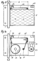
- FIG. 1 is the front view of a corresponding device is shown.
- the device is designed as a flat component and is connected to the corresponding conductor 1 with its one narrow edge.
- the device housing is made of plastic, for example.
- the front surface of the device which can be seen in FIG. 1, can be used for labeling with letters or numbers.
- the overall device is a flat component made up of a plurality of component planes joined to one another and arranged in a dimensionally stable body.
- the first plane facing natural light according to FIG. 1 is formed by a plate which transmits a magnetic field.
- the second level consists of the same material and comprises the solar cell 7 together with the associated conductor tracks 9.
- the conductor tracks lead to transfer points which can be plated through, so that the drive unit according to FIG. 6 can be brought into an electrically conductive connection with the solar cell 7.
- the third level of the component is, according to FIG. 3, through the shielding 3 of the data carrier with a slot design 5 formed.
- the area of the data carrier 2 to be overwritten is released through the slot 5.
- the through-plating for the power supply line can be seen in drawing figure 3 at the top right.
- the data carrier 2, which represents the actual sensor, is located in the fourth level, which is shown in FIG. 4.
- the sensor is a premagnetized disk, such as is used in floppy disks.
- the magnetization takes place in the tracks corresponding to the open slot 5 to 6.
- the plated-through hole can be seen at the top right at this level as well.
- FIG. 6 A variant of the drive according to FIG. 6 is shown in FIG.
- the drive is formed by a solar-powered watch drive 16, the corresponding axis being rotated differently via correspondingly designed gears and pinions.
- Such a clock drive also enables the arrangement of several data carriers 2 one above the other, each data carrier being driven by an axis segment in the central region 17 of the drive according to FIG. 7.
- the disk-like data carriers 2 can be used, for example, to record hours, days, months and years.
- the data carrier 2 can be pushed out of the device downwards or to the side or also upwards in order to accommodate the data carrier 2 to replace.
- the design according to the invention makes it possible to rotate the data carrier 2 in its position analogously to the time axis, the time axis being able to be driven in any desired form, for example mechanically, electrically, pneumatically, hydraulically or also chemically.
- a magnetic tape cassette 18 is provided, which has a magnetic tape 19 which can be unwound from a winding shaft 20 and wound onto another winding shaft 21, which Magnetic tape is guided over deflection rollers and runs radially to the electrical conductor 1 in its own measuring range 22.
- a shield 5 or 6 which, however, does not have a slot, but rather leaves the actual measuring area 22 free.
- the length of the Measuring range is indicated at L.
- the cassette 18 is coupled to a drive 23, which in turn can be solar powered.
- a data carrier is shown which is formed by a sensor 18 recording optical signals, for example a negative film.
- a drive 23, a processor 26, a counter 27 and a magnetic sensor 24 are also provided here, which are linked via the processor 26. After triggering the magnetic sensor, the drive 23 can be started. The events are then also counted. The optical detection takes place via an LED 29, which is electrically coupled in a suitable manner at 30 to the electrical conductor 1, so that In the event of an overcurrent event, the LED lights up brighter or darker depending on the strength of the overvoltage event. In this way, the corresponding overvoltage event is recorded in terms of strength in the corresponding measuring range 31, which is indicated by an arrow, the time assignment being made by rotating the transducer 28.
- a corresponding magnetic track 42 is formed in the embodiment according to FIG.
- the recess 43 is a code that can be processed by the corresponding reader.
- additional information-bearing signals that can be picked up optically or mechanically are to be transmitted.
- a barcode 44 or an embossing 45 or perforations 46 can be used to permanently enter data that can be read in a corresponding reading device.
- recording parameters, properties of the magnetic layer, recording data, series membership, frequency responses and other essential information can be stored with this.
- the corresponding Codings can be read using optical readers or mechanical scans.
Landscapes
- Physics & Mathematics (AREA)
- General Physics & Mathematics (AREA)
- Photovoltaic Devices (AREA)
- Recording Or Reproducing By Magnetic Means (AREA)
- Locating Faults (AREA)
- Recording Measured Values (AREA)
- Measurement Of Current Or Voltage (AREA)
Abstract
Description
Die Erfindung betrifft eine Vorrichtung zur Erfassung von Stoßströmen an Blitzableitern, Überspannungsableitern oder anderen von Stoßströmen oder von impulsförmigen Strömen (Kurzschluß- oder Erdschlußströmen) durchflossenen elektrischen Leitern, wobei ein mit Speicherdaten belegter magnetisierbarer Datenträger in einer räumlichen Zuordnung zu einem von Stoßströmen durchströmbaren elektrischen Leiter angeordnet ist, so daß im Falle eines Stoßstromes mindestens eine mit Speicherdaten belegte Zone des Datenträgers in dem durch den Stoßstrom um den Leiter entstehenden Magnetfeld angeordnet ist.The invention relates to a device for detecting surge currents on lightning arresters, surge arresters or other electrical conductors through which surge currents or pulse-shaped currents (short-circuit or earth leakage currents) flow, wherein a magnetizable data carrier occupied with storage data is arranged in a spatial association with an electrical conductor through which surge currents can flow is so that in the event of a surge current at least one zone of the data carrier occupied with storage data is arranged in the magnetic field created by the surge current around the conductor.
Eine derartige Vorrichtung ist beispielsweise aus der DE 38 23 389 C1 bekannt. Die dort beschriebene Vorrichtung ist geeignet, ein Überspannungsereignis festzustellen, ohne daß jedoch die Anzahl von Ereignissen und die zeitliche Abfolge von Ergeignissen festgehalten werden könnte. Es ist lediglich möglich, das der Größenordnung nach stärkste Ereignis zu erfassen. Auf diese Weise kann zwar der Beweis geführt werden, daß ein Ableiter über Jahre hinaus seine Aufgabe erfüllt hat, jedoch ist es nicht möglich, die Ereignisse im einzelen aufzugliedern und zeitlich zuzuordnen.Such a device is known for example from DE 38 23 389 C1. The device described there is suitable for determining an overvoltage event, without, however, the number of events and the chronological sequence of events could be recorded. It is only possible to record the strongest event in terms of magnitude. In this way, it can be proven that a surge arrester has fulfilled its task for years, but it is not possible to break down the events in detail and to assign them in time.
Ausgehend von diesem Stand der Technik liegt der Erfindung die Aufgabe zugrunde, eine Vorrichtung gattungsgemäßer Art zu schaffen, mit der es möglich ist, Überspannungsereignisse quantitativ und qualitativ über einen längeren Zeitraum zu erfassen und solche Ereignisse auch zuordnen zu können.Based on this prior art, the object of the invention is to create a device of the generic type with which it is possible to quantitatively and qualitatively record overvoltage events over a longer period of time and also to be able to assign such events.
Zur Lösung dieser Aufgabe wird vorgeschlagen, daß der Datenträger relativ zum elektrischen Leiter kontinuierlich oder in Stufen diskontinuierlich über den Verlauf einer Erfassungszeit derart verstellbar ist, daß entsprechend dem Zeitablauf jeweils andere auf die erste mit Speicherdaten belegte Zone folgende mit Speicherdaten belegte Zonen in dem durch einen Stoßstrom um den Leiter entstehenden Magnetfeld angeordnet sind.To solve this problem, it is proposed that the data carrier relative to the electrical conductor can be adjusted continuously or discontinuously in stages over the course of a detection time in such a way that, in accordance with the passage of time, other zones following the first occupied with storage data and occupied by storage data in the zone occupied by a Surge current around the conductor resulting magnetic field are arranged.
Der Datenträger kann im Prinzip beliebige Form haben, wobei es lediglich erforderlich ist, den Datenträger so anzuordnen und zu schützen, daß lediglich eine für den Ereignisfall vorgesehene mit Speicherdaten belegte Zone jeweils im Einflußbereich des von Stoßströmen durchfließbaren elektrischen Leiters angeordnet ist, und den Datenträger entweder kontinuierlich oder auch diskontinuierlich im Minuten-, Stunden- oder Tagesrhythmus derart zu verstellen, daß nach Ablauf einer ersten Zeitperiode die erste mit Speicherdaten belegte Zone ausgeblendet und eine folgende mit Speicherdaten belegte Zone eingeblendet wird, die dann zur Aufnahme von weiteren Überspannungsereignissen bereit ist. Durch diese Ausbildung ist eine eindeutige zeitliche Zuordnung von Überspannungsereignissen möglich, wobei zudem auch nicht nur das stärkste Überspannungsereignis, sondern jedes Überspannungsereignis aufgezeichnet werden kann. Die Abfrage des Datenträgers kann mit geeigneten Lesegeräten erfolgen.In principle, the data carrier can have any shape, it being only necessary to arrange and protect the data carrier in such a way that only one intended for the event is occupied with storage data Zone is arranged in each case in the area of influence of the electrical conductor through which surge currents can flow, and the data carrier is adjusted either continuously or discontinuously in minute, hour or day rhythm such that after a first period of time the first zone occupied with storage data is hidden and a subsequent one with Memory data occupied zone is faded in, which is then ready to record further overvoltage events. This configuration enables an unambiguous assignment of overvoltage events, whereby not only the strongest overvoltage event, but also each overvoltage event can be recorded. The data carrier can be queried using suitable readers.
Eine bevorzugte Weiterbildung wird darin gesehen, daß der Datenträger eine mit einem Drehantrieb gekoppelte Scheibe ist.A preferred development is seen in the fact that the data carrier is a disk coupled to a rotary drive.
Der Datenträger kann beispielsweise mit einer Halterung an einem Blitzableiter oder dergleichen elektrischen Leiter befestigt werden, wobei der Datenträger quer von dem entsprechenden Leiter einseitig abragend gehalten ist.The data carrier can, for example, be fastened to a lightning conductor or similar electrical conductor with a holder, the data carrier being held on one side and projecting transversely from the corresponding conductor.
Desweiteren ist bevorzugt vorgesehen, daß der Datenträger scheiben- oder plattenförmig ausgebildet und quer von einem von Stoßstrom durchströmbaren Leiter abragend gehaltert ist, wobei der Datenträger an seiner großflächigen Ober- und Unterseite mit einer Abschirmung zur Abschirmung gegen das Magnetfeld des Leiters versehen ist, die lediglich einen schmalen, zum Leiter hin gerichteten Schlitz aufweist, durch den jeweils die mit Speicherdaten belegte Zone definiert ist, die in dem um den Leiter entstehenden Magnetfeld von diesem beeinflußbar ist.Furthermore, it is preferably provided that the data carrier is disk-shaped or plate-shaped and is held transversely by a conductor through which surge current can flow, with the data carrier on it Large surface top and bottom is provided with a shield for shielding against the magnetic field of the conductor, which only has a narrow slot directed towards the conductor, through which the zone occupied by storage data is defined, which in the magnetic field of around the conductor this can be influenced.
Durch diese Anordnung ist in einfacher Weise die Ausblendung und Einblendung von entsprechenden mit Speicherdaten belegten Zonen durch Drehung des Datenträgers um eine mittige Achse möglich, wobei die Drehachse des Datenträgers quer zum Verlauf des elektrischen Leiters und orthogonal zur rechtwinklig vom Leiter abragenden Scheibenfläche gerichtet ist.This arrangement makes it possible in a simple manner to fade out and fade in corresponding zones occupied with memory data by rotating the data carrier about a central axis, the axis of rotation of the data carrier being directed transversely to the course of the electrical conductor and orthogonally to the pane surface projecting at right angles from the conductor.
Desweiteren ist bevorzugt vorgesehen, daß der Datenträger mit einer eigenen Energiequelle, vorzugsweise einer Solarzelle, zur Versorgung des Drehantriebes ausgestattet ist. Dabei kann bevorzugt vorgesehen sein, daß die Solarzelle durch eine bei Inbetriebnahme entfernbare Schutzfolie abgedeckt ist.Furthermore, it is preferably provided that the data carrier is equipped with its own energy source, preferably a solar cell, for supplying the rotary drive. It can preferably be provided that the solar cell is covered by a protective film that can be removed during commissioning.
Besonders bevorzugt ist vorgesehen, daß die Vorrichtung ein Flachbauteil mit mehreren aufeinander gefügten Bauteilebenen ist, die vorzugsweise in einem formfesten Körper angeordnet sind, wobei die dem natürlichen Licht zugewandte erste Ebene durch eine ein Magnetfeld durchlassende Platte mit einem Fenster für den Lichtdurchtritt zur Solarzelle ist, die zweite Ebene die Solarzelle nebst zugehöriger Leiterbahnen umfaßt, die dritte Ebene durch die Abschirmung des Datenträgers mit Schlitzausbildung gebildet ist, die vierte Ebene durch eine Einschubhalterung für einen Datenträger in Diskettenform gebildet ist, die fünfte Ebene die zweite Abschirmung nebst Schlitzdurchlaß für den Datenträger bildet und die sechste Ebene den mit dem Datenträger in Eingriff bringbaren Drehantrieb umfaßt, der mit den Leiterbahnen der Solarzelle kontaktiert ist.It is particularly preferably provided that the device is a flat component with a plurality of component levels joined to one another, which are preferably arranged in a dimensionally stable body, the first level facing natural light being passed through a plate with a window for the passage of a magnetic field Light passage to the solar cell is, the second level comprises the solar cell and associated conductor tracks, the third level is formed by the shielding of the data carrier with a slot formation, the fourth level is formed by an insert holder for a data carrier in disk form, the fifth level is the second shielding and slot opening forms for the data carrier and the sixth level comprises the rotary drive which can be brought into engagement with the data carrier and which is in contact with the conductor tracks of the solar cell.
Eine unter Umständen bevorzugte Ausbildung wird darin gesehen, daß der Antrieb, insbesondere Drehantrieb, des Datenträgers durch ein elektrisch angetriebenes Zahnrad mit Schrittantrieb und Rücklaufsperre gebildet ist.A possibly preferred embodiment is seen in the fact that the drive, in particular rotary drive, of the data carrier is formed by an electrically driven gearwheel with step drive and backstop.
Alternativ kann auch vorgesehen sein, daß der Antrieb, insbesondere Drehantrieb, des Datenträgers ein elektrischer Uhrantrieb ist.Alternatively, it can also be provided that the drive, in particular rotary drive, of the data carrier is an electrical clock drive.
Eine alternative Ausführungsform wird darin gesehen, daß der Datenträger eine Magnetbandkassette ist, die durch eine Abschirmung gegen ein durch Stoßströme erzeugtes Magnetfeld abgeschirmt ist, mit Ausnahme eines zwischen Umlenkrollen befindlichem aktuellen Meßbereiches.An alternative embodiment is seen in the fact that the data carrier is a magnetic tape cassette which is shielded by a shield against a magnetic field generated by surge currents, with the exception of a current measuring range located between deflection rollers.
Dabei ist bevorzugt vorgesehen, daß die Kassette mit einem Antrieb gekoppelt ist, der durch einen Magnetsensor einschaltbar ist, der im vom Stoßstrom durchflossenen Leiter erzeugten Magnetfeld liegt, wobei zudem vorzugsweise die Kassette im den Meßbereich verlassenden Magnetbandbereich einen Schreibkopf zur Aufzeichnung des Ereignisdatums auf das Magnetband sowie einen elektrischen Zähler zur Zählung der Anzahl der Ereignisse aufweist.It is preferably provided that the cassette is coupled to a drive that can be switched on by a magnetic sensor that flows through the surge current Conductor-generated magnetic field is located, the cassette also preferably having a write head for recording the event date on the magnetic tape in the magnetic tape area leaving the measuring area and an electrical counter for counting the number of events.
Eine alternative Möglichkeit zur Aufzeichnung von Überspannungsereignissen wird darin gesehen, daß der Datenträger durch einen optische Signale aufzeichnenden Aufnehmer gebildet ist, der mit einer durch Stoßströme energiesierbaren Lichtquelle, insbesondere einer LED, in einer bestimmbaren Zone belichtbar ist, wobei der Datenträger vorzugsweise als Scheibe oder Band mit Antriebsmitteln ausgebildet ist.An alternative possibility for recording overvoltage events is seen in the fact that the data carrier is formed by an optical signal recording transducer which can be exposed in a determinable zone with a light source, in particular an LED, which can be energized by surge currents, the data carrier preferably being in the form of a disc or tape is formed with drive means.
Dabei ist der optische Signale aufzeichnende Datenträger alternativ zu dem Datenträger gemäß Anspruch 1 vorgesehen, wobei zudem das Signal über ein Überspannungsereignis nicht durch unmittelbare Einwirkung und Aufzeichnung von Magnetfeldern gebildet wird, sondern das Überspannungsereignis wird durch die engergiesierbare Lichtquelle signalisiert.In this case, the data carrier recording optical signals is provided as an alternative to the data carrier according to
Alternativ zu den vorbeschriebenen Lösungen kann auch vorgesehen sein, daß der elektrische Leiter mit einem über den Verlauf einer Erfassungszeit kontinuierlich oder diskontinuierlich relativ zur Datenzone verstellbaren das Magnetfeld der Datenzone im Ereignisfall beeinflußenden Element verbunden ist oder dieses Element bildet, so daß entsprechend dem Zeitablauf jeweils andere auf die erste mit Speicherdaten belegte Zone folgende mit Speicherdaten belegte Zonen in dem durch das Element bei auftretenden Stoßströmen im von Stoßstrom durchfließbaren elektronischen Leiter erzeugten Magnetfeld angeordnet sind.As an alternative to the above-described solutions, it can also be provided that the electrical conductor with a magnetic field of the data zone that can be adjusted continuously or discontinuously relative to the data zone over the course of a detection time in the event of an event influencing element is connected or forms this element, so that in accordance with the passage of time, other zones following the first zone occupied with memory data and occupied with memory data are arranged in the magnetic field generated by the element when surge currents occur in the electronic conductor through which surge current can flow.
Dabei kann auch vorgesehen sein, daß der Datenträger eine optisch beeinflußbare Datenzonte aufweist und das verstellbare Element eine optische Signalquelle, insbesondere eine Lichtquelle, ist, die durch auftretende Stoßströme im elektrischen Leiter energiesierbar ist.It can also be provided that the data carrier has an optically influenceable data zone and the adjustable element is an optical signal source, in particular a light source, which can be energized by impulse currents occurring in the electrical conductor.
Desweiteren kann alternativ zu den vorbeschriebenen Lösungen vorgesehen sein, daß die Vorrichtung aus einem im Stoßstromauftrittsfalle (Ereignisfalle) im Magnetfeld des des von Stoßstrom durchflossenen Leiters angeordneten Sensor besteht, der mit einem Microcomputer oder Microcontroller in leitender Verbindung steht, mittels dessen der Ereignisfall mindestens der Häufigkeit nach erfaßbar ist und der mit einem elektronischen Datenspeicher kommuniziert, mittels dessen die Ereignisse abrufbar aufzuzeichnen sind.Furthermore, as an alternative to the solutions described above, it can be provided that the device consists of a sensor in the magnetic field of the conductor through which the surge current flows, which is in conductive connection with a microcomputer or microcontroller, by means of which the event occurs at least the frequency is detectable and communicates with an electronic data storage device by means of which the events can be recorded and retrieved.
Dabei ist vorzugsweise vorgesehen, daß der Sensor ein Magnetsensor ist.It is preferably provided that the sensor is a magnetic sensor.
Bei allen Ausführungsformen kann zudem vorgesehen sein, daß auf dem Datenträger weitere, von Stoßströmen oder deren Begleiterscheinungen nicht löschbare Daten optisch oder mechanisch ablesbar abgelegt sind.In all embodiments, it can also be provided that more, of surge currents or whose side effects are non-erasable data stored optically or mechanically readable.
Auch kann bevorzugt vorgesehen sein, daß der Datenträger in miniaturisierter Form ausgebildet ist und an einem, vorzugsweise scheckkartengroßen, Adapter lösbar befestigbar ist.It can also preferably be provided that the data carrier is designed in a miniaturized form and can be detachably attached to an adapter, preferably the size of a credit card.
Ausführungsbeispiele der Erfindung sind in den Zeichnungs-figuren 1 bis 17 dargestellt und im folgenden näher beschrieben.Embodiments of the invention are shown in the drawing figures 1 to 17 and described in more detail below.
In Figur 1 bis 6 ist eine erste Ausführungsform dargestellt. Die Vorrichtung zur Erfassung von Stoßströmen an Blitzableitern, Überspannungsableitern oder anderen von Stoßströmen durchflossenen elektrischen Leitern 1 besteht gemäß diesem Ausführungsbeispiel aus einem mit Speicherdaten belegten magnetisierten Datenträger 2, der in einer räumlichen Zuordnung zu dem von Stoßströmen durchströmbaren elektrischen Leiter 1 angeordnet ist. Dazu ist ein später noch beschriebenes Gehäuse ausgebildet, welches an dem elektrischen Leiter 1 befestigbar ist. Die Anordnung des Datenträgers 2 erfolgt in der Weise an dem elektrischen Leiter 1, daß im Falle eines Stoßstromes eine mit Speicherdaten belegte Zone des Datenträgers 2 in dem durch den Stoßstrom um den Leiter 1 entstehenden Magnetfeld angeordnet ist. Der Datenträger 2 ist über einen beispielsweise in Figur 6 dargestellten Antrieb relativ zum elektrischen Leiter 1 kontinuierlich oder in Stufen diskontinuierlich über den Verlauf einer Erfassungszeitperiode drehbar, so daß entsprechend dem Zeitablauf jeweils andere auf die erste mit Speicherdaten belegte Zone folgende mit Speicherdaten belegte Zonen indem durch einen Stoßstrom um den Leiter 1 entstehenden Magnetfeld angeordnet sind.A first embodiment is shown in FIGS. 1 to 6. According to this exemplary embodiment, the device for detecting surge currents on lightning arresters, surge arresters or other
Der Datenträger ist im Ausführungsbeispiel gemäß Figur 4 eine mit einem Drehantrieb gemäß Figur 6 gekoppelte Scheibe. Der scheibenförmige Datenträger 2 ist quer von dem vom Stoßstrom durchströmbaren Leiter 1 abragend gehaltert, wobei die Fläche der Scheibe 2 in einer Ebene liegt, die auch von der Mittelachse des Leiters 1 gebildet ist. Gemäß Zeichnungsfigur 3 und 5 ist der Datenträger 2 an seiner großflächigen Ober- und Unterseite mit einer Abschirmung 3 bzw. 4 gegen das Magnetfeld des Leiters 1 versehen, wobei die Abschirmung 3 bzw. 4 lediglich eine schmalen zum Leiter 1 hin gerichteten Schlitz 5 bzw. 6 aufweist, der quasi von der Mitte des Datenträgers 2 radial bis zu der dem Leiter 1 zugewandten Randkante des Datenträger 2 verläuft. Durch diese Schlitze 5, 6 ist jeweils die mit Speicherdaten belegte Zone definiert, die in dem um den Leiter 1 entstehenden Magnetfeld von diesem beeinflußbar ist. Der übrige Bereiche des Datenträgers 2 ist durch die Abschirmung 3, 4 geschützt. Der Datenträger 2 ist zusätzlich mit einer eigenen Energiequelle in Form einer Solarzelle 7 zur Versorgung des Drehantriebes gemäß Figur 6 versehen. Die Solarzelle 7 ist durch eine bei der ersten Inbetriebnahme entfernbare Schutzfolie 8 abgedeckt. In der Zeichnungsfigur 1 ist die Vorderansicht einer entsprechenden Vorrichtung gezeigt. Die Vorrichtung ist als Flachbauelement ausgebildet und an dem entsprechenden Leiter 1 mit ihrer einen schmalen Randkante angeschlossen. Das Vorrichtungsgehäuse besteht beispielsweise aus Kunststoff. Die Frontfläche der Vorrichtung, die in Figur 1 ersichtlich ist, kann zur Kennzeichnung mit Buchstaben oder Zahlen genutzt werden. Sie weist auch ein Energieversorgungsfeld auf, welches zunächst herstellerseitig mit einer Schutzfolie 8 abgedeckt ist. Erst nach erfolgter Montage des Erfassungsgerätes wird die Schutzfolie 8 abgezogen und damit das Gerät aktiviert. Auf der Geräterückseite kann ein Beschriftungsfeld vorgesehen sein, in welchem das Datum der Inbetriebnahme festgehalten werden kann.In the exemplary embodiment according to FIG. 4, the data carrier is a disk coupled to a rotary drive according to FIG. 6. The disk-
Die Gesamtvorrichtung ist ein Flachbauteil aus mehreren aufeinander gefügten Bauteilebenen, die in einem formfesten Körper angeordnet sind. Die dem natürlichen Licht zugewandte erste Ebene gemäß Figur 1 ist durch eine ein Magnetfeld durchlassende Platte gebildet. Die zweite Ebene besteht aus ebensolchem Material und umfaßt die Solarzelle 7 nebst zugehöriger Leiterbahnen 9. Die Leiterbahnen führen zu Übergabestellen, die durchkontaktierbar sind, so daß die Antriebseinheit gemäß Figur 6 mit der Solarzelle 7 in elektrisch leitender Verbindung gebracht werden kann.The overall device is a flat component made up of a plurality of component planes joined to one another and arranged in a dimensionally stable body. The first plane facing natural light according to FIG. 1 is formed by a plate which transmits a magnetic field. The second level consists of the same material and comprises the
Die dritte Ebene des Bauteiles ist gemäß Figur 3 durch die Abschirmung 3 des Datenträgers mit Schlitzausbildung 5 gebildet. Durch den Schlitz 5 wird der zu überschreibende Bereich des Datenträger 2 freigegeben. Durch die Gestaltung des Schlitzes kann sowohl der erfaßte Zeitabschnitt als auch die Empfindlichkeit festgelegt werden. In Zeichnungsfigur 3 rechts oben ist die Durchkontaktierung für die Stromzuführung erkennbar. Der Datenträger 2, der den eigentlichen Sensor darstellt, befindet sich in der vierten Ebene, die in Figur 4 gezeigt ist. Im Ausführunsbeispiel ist der Sensor eine vormagnetisierte Scheibe, wie sie beispielsweise in Disketten eingesetzt wird. Die Vormagnetisierung erfolgt in den Spuren, die dem offenen Schlitz 5 bis 6 entsprechen. Je nach Erfassungszeitraum können unterschiedliche Spurenzahlen vorhanden sein. Beispielsweise können 365 Spuren für die Erfassung eines Jahrenzeitraumes vorgesehen sein. Auch bei dieser Ebene ist die Durchkontaktierung oben rechts erkennbar.The third level of the component is, according to FIG. 3, through the
In Figur 5 ist die fünfte Ebene gezeigt, die wiederum eine Abschirmung 4 mit entsprechender Schlitzausbildung 6 umfaßt. Die Abschirmung ist ferner im Mittelbereich bei 10 gelocht, da hier der Antrieb für den Datenträger 2 durchgreifen muß.FIG. 5 shows the fifth level, which in turn comprises a
In Figur 6 ist der Antrieb des Datenträgers 2 prinzipiell dargestellt. Der Drehantrieb umfaßt eine drehbar gelagerte Scheibe 11, die analog zum Erfassungszeitraum Zahnungen aufweist, beispielsweise 365 Zahnungen im Randbereich 12. Eine Rücklaufsperre 13 sorgt dafür, daß die Scheibe 11 nur in einer Richtung bewegbar ist. Die Energie zum Antrieb des Antriebes der Scheibe 11 wird duch die Solarzelle direkt oder indirekt einem Hubmagneten 14 zugeführt, wobei bei Tageslicht die Scheibe um einen Zahn weiter bewegt wird. Bei Dunkelheit geht der Hubmagnet 14 wieder in die Ausgangsposition zurück. Bei auftretendem erneuten Tageslicht wird der Hubmagnet erregt und über den Eingriff der Klinke 15 die Scheibe entsprechend um eine Zahnung weitergedreht. Günstig auf die Belastung der Bauelement (Lebensdauer) können sich bekannte Schaltungen ausbilden, wie beispielsweise Triggerung (Schwellwert) oder auch Monoflops (nur 1 Impuls pro Tag). Mit diesen Schaltungen können natürlich auch die Arbeitsbedingungen der Vorrichtung festgelegt werden. In Figur 7 ist eine Variante des Antriebes gemäß Figur 6 gezeigt. Hierbei ist der Antrieb durch einen solarbetriebenen Uhrenantrieb 16 gebildet, wobei über entsprechend ausgelegte Zahnräder und Ritzel entsprechende Achse unterschiedlich gedreht werden. Ein solcher Uhrenantrieb ermöglicht auch die Anordnung von mehreren Datenträgern 2 übereinander, wobei jeder Datenträger von einem Achssegment im Mittelbereich 17 des Antriebes gemäß Figur 7 angetrieben wird. Die diskettenartigen Datenträger 2 können beispielsweise zur Aufzeichnung von Stunden, Tagen, Monaten und Jahren benutzt werden. Bezüglich des in Figur 4 gezeigten Bauteiles ist noch zu bemerken, daß der Datenträger 2 nach unten oder seitlich oder auch nach oben aus der Vorrichtung herausgeschoben werden kann, um den Datenträger 2 auszuwechseln.The drive of the
Durch die erfindungsgemäße Ausbildung ist es möglich, den Datenträger 2 analog zur Zeitachse in seiner Position zu drehen, wobei der Antrieb der Zeitachse in beliebiger Form erfolgen kann, beispielsweise mechanisch, elektrisch, pneumatisch, hydraulisch oder auch chemisch.The design according to the invention makes it possible to rotate the
Es ist auch möglich, den Drehantrieb oder dergleichen Antrieb durch einen von einem auftretenden Stoßstrom beeinflußbaren Schaltelement, z.B. einen Magnetschalter, zu steuern, so daß der Antrieb nur dann in Gang gesetzt wird, wenn ein Ereignisfall (Stoßstrom) aufgetreten ist. Damit verbunden könnte eine Datumseingabe vorgesehen sein, die ebenfalls durch den Ereignisfall in Gang gesetzt wird, so daß nicht nur der Ereignisfall, sondern auch die exakte Zeit des Ereignisses erfaßt und gespeichert werden kann.It is also possible to drive the rotary drive or the like by a switching element which can be influenced by a surge current, e.g. a magnetic switch to control, so that the drive is only started when an event (surge current) has occurred. In connection with this, a date input could be provided, which is also set in motion by the event, so that not only the event but also the exact time of the event can be recorded and stored.
Bei der der Ausführungform gemäß Figur 9 und 10 ist bei an sich ähnlichem Aufbau wie vor beschrieben anstelle des scheibenförmigen Datenträgers eine Magnetbandkassette 18 vorgesehen, die ein Magnetband 19 aufweist, welches von einer Wickelwelle 20 abwickelbar und auf eine andere Wickelwelle 21 aufwickelbar ist, wobei das Magnetband über Umlenkrollen geführt ist und in dem eigenen Meßbereich 22 radial zum elektrischen Leiter 1 verläuft. Auch hierbei ist eine Abschirmung 5 bzw. 6 vorhanden, die allerdings keinen Schlitz aufweist, sondern den eigentlichen Meßbereich 22 freiläßt. Die Länge des Meßbereiches ist bei L angegeben. Die Kassette 18 ist mit einem Antrieb 23 gekoppelt, der wiederum solarbetrieben sein kann. Der Antrieb 23 kann durch einen Magnetfeldsensor 24 eingeschaltet werden, der von dem um den Leiter 1 entstehenden Magnetfeld im Falle eines Überspannungsereignisses geschaltet wird. Es ist auch ein Permanentantrieb möglich. Desweiteren kann eine Schreibkopf 25 im Auslaufbereich des Meßbereiches 22 vorgesehen sein, mittels dessen auf dem Magnetband 19 ein Zeitmaßstab aufgebracht werden kann. Auch bei dieser Anordnung und Ausbildung ist es möglich, entsprechende Überspannungsereignisse der Anzahl und der Größe nach aufzuzeichnen und entsprechenden Zeiten zuzuordnen. Die Steuerung des Antriebes kann dabei mit einem Prozessor 26 gekoppelt sein, mittels dessen der Schreibkopf schaltbar ist und gegebenenfalls ein ebenfalls angeordneter Zähler 27 zur Zählung von Überspannungsereignissen in Gang gesetzt wird.In the embodiment according to FIGS. 9 and 10, with a structure similar to that described above, instead of the disk-shaped data carrier, a magnetic tape cassette 18 is provided, which has a
In der Ausführungsform gemäß Figur 11 ist ein Datenträger gezeigt, der durch einen optische Signale aufzeichnenden Aufnehmer 18 gebildet ist, beispielsweise einen Negativfilm. Auch hierbei ist wieder ein Antrieb 23, ein Prozessor 26, ein Zähler 27, ein Magnetsensor 24 vorgesehen, die über den Prozessor 26 verknüpft sind. Nach Auslösung des Magnetsensors kann der Antrieb 23 in Gang gesetzt werden. Desweiteren werden dann die Ereignisse gezählt. Die optische Erkennung erfolgt über eine LED 29, die elektrisch in geeigneter Weise bei 30 an den elektrischen Leiter 1 angekoppelt ist, so daß im Falle eines Überstromereignisses die LED je nach Stärke des Überspannungsereignisses heller oder dunkler leuchtet. Es wird auf diese Weise in dem entsprechenden Meßbereich 31, der durch einen Pfeil angegeben ist, das entsprechende Überspannungsereignis der Stärke nach aufgezeichnet, wobei durch Drehung des Aufnehmers 28 die zeitliche Zuordnung erfolgt.In the embodiment according to FIG. 11, a data carrier is shown which is formed by a sensor 18 recording optical signals, for example a negative film. A
In Figur 11 ist eine Kombination von magnetischer und optischer Aufzeichnungsmöglichkeit gezeigt, wobei dort der scheibenförmige Aufnehmer 28 als magnetisch optische Version ausgebildet ist. Auch hier erfolgt die Drehung der Scheibe 28 durch Ingangsetzung des Antriebes 23, der durch den Magnetsensor 24 im Ereignisfall ausgelöst wird. Die Schaltung wird durch den Prozessor 26 getriggert. Es kann auch die Aufzeichnung des Datums und die Zählung der Ereignisse im Zähler 27 erfolgen. Es kann eine magnet-optische Erkennung der Stromstärke erfolgen, wobei eine qualitativ auswertbare Aufzeichnung der Stromstärke über der Zeit erfolgt.FIG. 11 shows a combination of magnetic and optical recording options, the disc-shaped
In Figur 13 ist eine andere Möglichkeit einer Ausbildung einer entsprechenden Vorrichtung gezeigt. Hierbei können magnetisch wirksame Elemente 32 in ihrer Position durch einen geeigneten Antrieb derart beispielsweise in Richtung des Pfeiles 33 verschoben werden, daß sie eine Aufzeichnungsspur 34 eines kartenförmigen Datenträgers 35 derart beeinflussen, daß eine zeitliche Zuordnung im Ereignisfall möglich ist. Eine weitere alternative ist in Figur 14 gezeigt. Dabei besteht die Vorrichtung aus einem im Magnetfeld des vom Stoßstrom durchflossenen Leiters 1 angeordneten Magentsensor 36, der mit einem Microcomputer 37 in leitender Verbindung steht. Der Microcomputer 37 ist über eine Stromversorgung 38, beispielsweise eine Solarzelle elektrisch versorgt. Der Microcomputer 37 steht zudem mit einem Datenspeicher (ROM) 39 in Verbindung, der über eine Busleitung 40 an ein Lesegerät anschließbar ist. Bei dieser Ausbildung können die vom Magnetsensor erfaßten Ereignisse verarbeitet und gegebenenfalls sowohl zeitlich als auch größenordnungsmäßig zugeordnet und in dem Datenspeicher 39 abgelegt werden. Auch bei dieser Ausbildung ist die Vorrichtung 41 insgesamt als Karte in Form und Größe einer Scheckkarte ausgebildet.Another possibility of forming a corresponding device is shown in FIG. Here, magnetically
Auch bei den Ausbildungen gemäß Figur 15 bis 17 sind scheckkartenartige Ausbildungen vorgesehen. Dabei ist bei der Ausführungsform gemäß Figur 15 eine entsprechende Magnetspur 42 ausgebildet. Die Ausnehmung 43 ist eine Kodierung, die vom entsprechenden Lesegerät verarbeitet werden kann. Ergänzend sind hierbei zusätzliche Informationen tragende für ein Lesegerät optisch oder mechanisch abgreifbare Signale zu übermitteln. Beispielsweise können über einen Barcode 44 oder eine Prägung 45 oder auch Lochungen 46 Daten fest eingegeben werden, die in einem entsprechenden Lesegerät abgelesen werden können. Beispielsweise können hiermit Aufnahmeparameter, Eigenschaften der Magnetschicht, Aufnahmedaten, Serienzugehörigkeit, Frequenzgänge und andere wesentliche Informationen gespeichert werden. Die entsprechenden Kodierungen können durch optische Lesegeräte oder auch mechanische Abtastungen abgelesen werden.15 to 17, credit card-like training is also provided. A corresponding
Bei der Ausbildung gemäß Figur 16 und 17 ist der eigentliche Datenträger 47 nur ein Miniaturbauteil, welches die Anordnung an entsprechenden Leitern 1 in einfacher Weise ermöglicht. Allerdings ist diese Größe für die Handhabe insbesondere bei Lesegeräten nicht besonders vorteilhaft, so daß bei dieser Ausführungsform vorgesehen ist, daß der Datenträger 47 an einem scheckkartengroßen Adapter 48 lösbar befestigt ist, beispielsweise angeclipst ist. Der Adapter 48 weist eine Kodierung 49 auf, die vom Lesegerät auswertbar ist, so daß das Lesegerät erfassen kann, daß es sich um eine Miniaturisierung eines Datenträgers 47 handelt. Somit ist es möglich, auch solche kleinbauenden Magnetkarten in dem gleichen Lesegerät auszuwerten, wie Magnetkarten der Ausführungsform beispielsweise gemäß Figur 15.16 and 17, the
Die Erfindung ist nicht auf die Ausführungsbeispiele beschränkt, sondern im Rahmen der Offenbarung vielfach variabel.The invention is not limited to the exemplary embodiments, but is often variable within the scope of the disclosure.
Alle neuen, in der Beschreibung und/oder Zeichnung offenbarten Einzel- und Kombiantionsmerkmale werden als erfindungswesentlich angesehen.All new individual and combination features disclosed in the description and / or drawing are regarded as essential to the invention.
Claims (17)
Applications Claiming Priority (2)
| Application Number | Priority Date | Filing Date | Title |
|---|---|---|---|
| DE4401069A DE4401069C1 (en) | 1994-01-15 | 1994-01-15 | Device for detecting surge currents on lightning rods or the like |
| DE4401069 | 1994-01-15 |
Publications (2)
| Publication Number | Publication Date |
|---|---|
| EP0663598A2 true EP0663598A2 (en) | 1995-07-19 |
| EP0663598A3 EP0663598A3 (en) | 1997-05-28 |
Family
ID=6508000
Family Applications (1)
| Application Number | Title | Priority Date | Filing Date |
|---|---|---|---|
| EP94117805A Withdrawn EP0663598A3 (en) | 1994-01-15 | 1994-11-11 | Means for determining current pulses of lightning conductors or similar. |
Country Status (8)
| Country | Link |
|---|---|
| EP (1) | EP0663598A3 (en) |
| CZ (1) | CZ9595A3 (en) |
| DE (1) | DE4401069C1 (en) |
| FI (1) | FI950148A (en) |
| HU (1) | HUT69836A (en) |
| NO (1) | NO944845L (en) |
| PL (1) | PL175792B1 (en) |
| SK (1) | SK3095A3 (en) |
Cited By (3)
| Publication number | Priority date | Publication date | Assignee | Title |
|---|---|---|---|---|
| US7508186B2 (en) | 2003-06-12 | 2009-03-24 | Lm Glasfiber A/S | Registration of lightning strike in a wind turbine |
| CN103983837A (en) * | 2014-05-09 | 2014-08-13 | 广西南宁百兰斯科技开发有限公司 | Double-lightning-protection counter |
| EP3524986A1 (en) * | 2018-02-13 | 2019-08-14 | Erico International Corporation | Mobile card reader for lightning protection systems |
Families Citing this family (2)
| Publication number | Priority date | Publication date | Assignee | Title |
|---|---|---|---|---|
| DE102012009205A1 (en) | 2012-05-10 | 2013-11-14 | Phoenix Contact Gmbh & Co. Kg | Lightning current monitoring device |
| DE102018205549B3 (en) | 2018-04-12 | 2019-08-01 | Phoenix Contact Gmbh & Co. Kg | Separating element and ensemble comprising a corresponding separating element and an overvoltage protection element |
Citations (3)
| Publication number | Priority date | Publication date | Assignee | Title |
|---|---|---|---|---|
| US3889185A (en) * | 1974-04-15 | 1975-06-10 | Nasa | Lightning current measuring systems |
| DE3823389C1 (en) * | 1988-07-09 | 1989-08-24 | Obo Bettermann Ohg, 5750 Menden, De | |
| US5184215A (en) * | 1991-11-26 | 1993-02-02 | Niagara Mohawk Power Corporation | Lightning detecting and recording system |
Family Cites Families (2)
| Publication number | Priority date | Publication date | Assignee | Title |
|---|---|---|---|---|
| DE3544542A1 (en) * | 1985-12-17 | 1987-06-25 | Dieter Nier | Method and device for detecting surge voltages |
| AT397883B (en) * | 1991-10-24 | 1994-07-25 | Gerstmaier Siegfried | DEVICE FOR DISPLAYING AN ELECTRICITY THROUGHOUT IN CABLES OF LIGHTNING PROTECTION SYSTEMS |
-
1994
- 1994-01-15 DE DE4401069A patent/DE4401069C1/en not_active Expired - Fee Related
- 1994-11-11 EP EP94117805A patent/EP0663598A3/en not_active Withdrawn
- 1994-12-07 HU HU9403501A patent/HUT69836A/en unknown
- 1994-12-14 NO NO944845A patent/NO944845L/en unknown
-
1995
- 1995-01-10 SK SK30-95A patent/SK3095A3/en unknown
- 1995-01-13 CZ CZ9595A patent/CZ9595A3/en unknown
- 1995-01-13 PL PL95306796A patent/PL175792B1/en not_active IP Right Cessation
- 1995-01-13 FI FI950148A patent/FI950148A/en unknown
Patent Citations (3)
| Publication number | Priority date | Publication date | Assignee | Title |
|---|---|---|---|---|
| US3889185A (en) * | 1974-04-15 | 1975-06-10 | Nasa | Lightning current measuring systems |
| DE3823389C1 (en) * | 1988-07-09 | 1989-08-24 | Obo Bettermann Ohg, 5750 Menden, De | |
| US5184215A (en) * | 1991-11-26 | 1993-02-02 | Niagara Mohawk Power Corporation | Lightning detecting and recording system |
Non-Patent Citations (1)
| Title |
|---|
| 7TH INT. SYMPOSIUM ON HIGH VOLTAGE ENGINEERING, 26.August 1991, DRESDEN (D), Seiten 35-38, XP000617883 HORII, WADA: "Measurement of lightning current by the magentizing effect on magnetic tape" * |
Cited By (5)
| Publication number | Priority date | Publication date | Assignee | Title |
|---|---|---|---|---|
| US7508186B2 (en) | 2003-06-12 | 2009-03-24 | Lm Glasfiber A/S | Registration of lightning strike in a wind turbine |
| CN103983837A (en) * | 2014-05-09 | 2014-08-13 | 广西南宁百兰斯科技开发有限公司 | Double-lightning-protection counter |
| EP3524986A1 (en) * | 2018-02-13 | 2019-08-14 | Erico International Corporation | Mobile card reader for lightning protection systems |
| US10650296B2 (en) | 2018-02-13 | 2020-05-12 | Erico International Corporation | Mobile card reader for lightning protection systems |
| US11030503B2 (en) | 2018-02-13 | 2021-06-08 | Erico International Corporation | Mobile card reader for lightning protection systems |
Also Published As
| Publication number | Publication date |
|---|---|
| NO944845D0 (en) | 1994-12-14 |
| NO944845L (en) | 1995-07-17 |
| FI950148A (en) | 1995-07-16 |
| EP0663598A3 (en) | 1997-05-28 |
| HUT69836A (en) | 1995-09-28 |
| SK3095A3 (en) | 1995-08-09 |
| FI950148A0 (en) | 1995-01-13 |
| DE4401069C1 (en) | 1995-07-27 |
| CZ9595A3 (en) | 1995-08-16 |
| PL306796A1 (en) | 1995-07-24 |
| HU9403501D0 (en) | 1995-02-28 |
| PL175792B1 (en) | 1999-02-26 |
Similar Documents
| Publication | Publication Date | Title |
|---|---|---|
| DE2520581C3 (en) | Arrangement for erasable recording of measured quantities | |
| DE3507871C2 (en) | ||
| DE3148644T1 (en) | A CYLINDER LOCK COMBINATION, A LOCK CYLINDER AND A KEY FOR SUCH A COMBINATION | |
| EP0065083A1 (en) | Identitity card incorporating an IC chip | |
| EP0617818A1 (en) | Data carrier. | |
| DE1574153C3 (en) | Control device for checking reusable credit or identity cards with a recording medium | |
| DE4401069C1 (en) | Device for detecting surge currents on lightning rods or the like | |
| EP0350662A2 (en) | Process and appliance for determining pulse currents in lightning conductors or similar devices | |
| DE2452507C2 (en) | Device for storing and reading data consisting of binary characters | |
| DE3221217A1 (en) | MAGNETIC DISK CASSETTE | |
| DE9400656U1 (en) | Device for detecting surge currents on lightning rods or the like. | |
| DE4003212C2 (en) | ||
| DE4442193A1 (en) | Electronic counter module for water meter | |
| EP0180073B1 (en) | Data acquisition and registration device | |
| WO1993014501A1 (en) | Cassette with a recording medium for a recording device | |
| WO1993008571A1 (en) | Reader for the static memory of a cassette | |
| DE2229047C3 (en) | Photoelectric punch card reader | |
| DE2659640B1 (en) | Reader for cards with magnetic strip information - has leaf spring pressing card against Hall effect head with corrosion-resistant coating | |
| DE69816398T2 (en) | Disk drive adapter | |
| DE2107976A1 (en) | Device for the time-based automatic evaluation of diagrams | |
| DE19902736C2 (en) | Electronic revolution counter | |
| DE2139822C3 (en) | Rotating read-only memory for exchangeable data sets, especially the thickness values of font alphabets in perforators | |
| EP1014236A1 (en) | Programmable time switch | |
| DE1499565A1 (en) | Input device for the acquisition of characteristic data | |
| DE2435189A1 (en) | Rotary journey graph recorder - for twenty four hour recording mechanism draws two rotary graphs simultaneously on two different paper discs |
Legal Events
| Date | Code | Title | Description |
|---|---|---|---|
| PUAI | Public reference made under article 153(3) epc to a published international application that has entered the european phase |
Free format text: ORIGINAL CODE: 0009012 |
|
| AK | Designated contracting states |
Kind code of ref document: A2 Designated state(s): AT BE CH DE DK ES FR GB GR IE IT LI LU MC NL PT SE |
|
| PUAL | Search report despatched |
Free format text: ORIGINAL CODE: 0009013 |
|
| AK | Designated contracting states |
Kind code of ref document: A3 Designated state(s): AT BE CH DE DK ES FR GB GR IE IT LI LU MC NL PT SE |
|
| 17P | Request for examination filed |
Effective date: 19970613 |
|
| 17Q | First examination report despatched |
Effective date: 19990827 |
|
| GRAG | Despatch of communication of intention to grant |
Free format text: ORIGINAL CODE: EPIDOS AGRA |
|
| GRAG | Despatch of communication of intention to grant |
Free format text: ORIGINAL CODE: EPIDOS AGRA |
|
| GRAH | Despatch of communication of intention to grant a patent |
Free format text: ORIGINAL CODE: EPIDOS IGRA |
|
| STAA | Information on the status of an ep patent application or granted ep patent |
Free format text: STATUS: THE APPLICATION HAS BEEN WITHDRAWN |
|
| 18W | Application withdrawn |
Withdrawal date: 20020123 |