EP0663256B1 - A method and a machine for manufacturing crown or face gears - Google Patents
A method and a machine for manufacturing crown or face gears Download PDFInfo
- Publication number
- EP0663256B1 EP0663256B1 EP94119174A EP94119174A EP0663256B1 EP 0663256 B1 EP0663256 B1 EP 0663256B1 EP 94119174 A EP94119174 A EP 94119174A EP 94119174 A EP94119174 A EP 94119174A EP 0663256 B1 EP0663256 B1 EP 0663256B1
- Authority
- EP
- European Patent Office
- Prior art keywords
- axis
- gear
- disc tool
- pinion
- rotation
- Prior art date
- Legal status (The legal status is an assumption and is not a legal conclusion. Google has not performed a legal analysis and makes no representation as to the accuracy of the status listed.)
- Expired - Lifetime
Links
Images

Classifications
-
- B—PERFORMING OPERATIONS; TRANSPORTING
- B23—MACHINE TOOLS; METAL-WORKING NOT OTHERWISE PROVIDED FOR
- B23F—MAKING GEARS OR TOOTHED RACKS
- B23F19/00—Finishing gear teeth by other tools than those used for manufacturing gear teeth
- B23F19/10—Chamfering the end edges of gear teeth
-
- B—PERFORMING OPERATIONS; TRANSPORTING
- B23—MACHINE TOOLS; METAL-WORKING NOT OTHERWISE PROVIDED FOR
- B23F—MAKING GEARS OR TOOTHED RACKS
- B23F15/00—Methods or machines for making gear wheels of special kinds not covered by groups B23F7/00 - B23F13/00
- B23F15/06—Making gear teeth on the front surface of wheels, e.g. for clutches or couplings with toothed faces
-
- B—PERFORMING OPERATIONS; TRANSPORTING
- B23—MACHINE TOOLS; METAL-WORKING NOT OTHERWISE PROVIDED FOR
- B23F—MAKING GEARS OR TOOTHED RACKS
- B23F17/00—Special methods or machines for making gear teeth, not covered by the preceding groups
- B23F17/005—Special methods or machines for making gear teeth, not covered by the preceding groups for machining tooth fillet or tooth root
-
- B—PERFORMING OPERATIONS; TRANSPORTING
- B23—MACHINE TOOLS; METAL-WORKING NOT OTHERWISE PROVIDED FOR
- B23F—MAKING GEARS OR TOOTHED RACKS
- B23F19/00—Finishing gear teeth by other tools than those used for manufacturing gear teeth
- B23F19/002—Modifying the theoretical tooth flank form, e.g. crowning
-
- B—PERFORMING OPERATIONS; TRANSPORTING
- B23—MACHINE TOOLS; METAL-WORKING NOT OTHERWISE PROVIDED FOR
- B23F—MAKING GEARS OR TOOTHED RACKS
- B23F23/00—Accessories or equipment combined with or arranged in, or specially designed to form part of, gear-cutting machines
- B23F23/12—Other devices, e.g. tool holders; Checking devices for controlling workpieces in machines for manufacturing gear teeth
- B23F23/1237—Tool holders
- B23F23/1262—Grinding disc holders; Disc-type milling-cutter holders
-
- Y—GENERAL TAGGING OF NEW TECHNOLOGICAL DEVELOPMENTS; GENERAL TAGGING OF CROSS-SECTIONAL TECHNOLOGIES SPANNING OVER SEVERAL SECTIONS OF THE IPC; TECHNICAL SUBJECTS COVERED BY FORMER USPC CROSS-REFERENCE ART COLLECTIONS [XRACs] AND DIGESTS
- Y10—TECHNICAL SUBJECTS COVERED BY FORMER USPC
- Y10T—TECHNICAL SUBJECTS COVERED BY FORMER US CLASSIFICATION
- Y10T409/00—Gear cutting, milling, or planing
- Y10T409/10—Gear cutting
- Y10T409/101431—Gear tooth shape generating
- Y10T409/10477—Gear tooth shape generating by relative axial movement between synchronously indexing or rotating work and cutter
-
- Y—GENERAL TAGGING OF NEW TECHNOLOGICAL DEVELOPMENTS; GENERAL TAGGING OF CROSS-SECTIONAL TECHNOLOGIES SPANNING OVER SEVERAL SECTIONS OF THE IPC; TECHNICAL SUBJECTS COVERED BY FORMER USPC CROSS-REFERENCE ART COLLECTIONS [XRACs] AND DIGESTS
- Y10—TECHNICAL SUBJECTS COVERED BY FORMER USPC
- Y10T—TECHNICAL SUBJECTS COVERED BY FORMER US CLASSIFICATION
- Y10T409/00—Gear cutting, milling, or planing
- Y10T409/10—Gear cutting
- Y10T409/107791—Using rotary cutter
- Y10T409/10795—Process
Definitions
- the present invention relates to a method according to claim 1 and a machine according to the preamble of claim 5 for manufacturing gears and, in particular gears adapted to mesh with cylindrical pinions, of the type commonly known in the trade as face gears.
- EP-A-0 330 289 representing the closest prior art to use disc tools which finish the flanks by working on the principle of generatrices and which have a peripheral cutting portion, the half-section of which, defined by a plane passing through the axis of rotation of the disc tool, has a cutting profile which is similar to the profile of the teeth of the aforesaid cylindrical pinion.
- the disc tool is driven in cycle in which it is reciprocated relative to the gear to be cut along a path perpendicular to the axis of rotation of the disc tool itself and is pivoted about an axis which is also perpendicular to the axis of rotation of the disc tool; at the same time as the disc tool is pivoted about this latter axis, the gear to be cut is rotated about its own axis in such a way that the ratio of the speed of pivoting of the disc tool to the speed of rotation of the gear being cut is always exactly the same as the transmission ratio resulting from the meshing of the gear with the pinion.
- disc tools of the type just described have several disadvantages, all owing to the fact that their manufacture is relatively complex and very expensive.
- the theoretical contour of the gear teeth must be corrected in order to avoid relative slipping of the teeth of the gear and those of the pinion and, as the entire cutting operation is carried out without varying the ratio between the speeds of pivoting of the tool and rotation of the gear, the cutting portion of the disc tool needs to have a cutting profile which is different from the contour of the pinion teeth and, in particular, must be worked in such a way as to take account of the aforesaid contour correction, thus incurring not inconsiderable manufacturing costs and problems.
- the object of the present invention is to provide a method for the manufacture of face gears which overcomes the aforesaid disadvantages both simply and inexpensively.
- the present invention also relates to a machine for the manufacture of face gears.
- a machine for the manufacture of a face gear having the features of claim 5.
- a machine for cutting or finishing a gear 2, of the type commonly known in the trade as a face gear, adapted to mesh with a cylindrical pinion 3 ( Figure 4) defining its own axis 4.
- the machine 1 is operated and controlled by a central electronic unit 5, in itself known, and includes a frame 6 which includes in turn a base 7 and a vertical wall 8 extending upwardly perpendicular to the base 7.
- the base 7 carries a securely fixed straight guide 9 to which is coupled a slide 10 slidable on the guide 9 along a line of action 11 ( Figures 2 and 3) driven by a known actuator assembly 12 ( Figure 1) controlled by the central, unit 5.
- the slide 10 supports a worktable 13 which is fixed to the slide 10 for rotation about an axis 14 perpendicular to the line of action 11, is rotatable about this axis 14 by an actuator assembly 15 ( Figure 2), per se known and controlled by the central unit 5, and adapted to support and retain the gear 2 to be worked, arranged with its axis coincident with the axis 14.
- a further straight guide 16 is fixed to the wall 8 so as to extend horizontally perpendicular to the line of action 11 and has a slide 18 coupled thereto for axial sliding movement.
- This slide 18 is movable on the guide 16 along a line of action 19, by a lead screw assembly 20 actuated by a motor 21 ( Figure 1) controlled by the central unit 5, and supports a guide 22 of an additional slide assembly 23.
- This slide assembly 23 comprises the guide 22 and a slide 24 slidably fixed thereto and movable along the guide 22 itself along a line of action 25 perpendicular to the lines of action 11 and 19 driven via known transmission means by a motor 26 also controlled by the central unit 5.
- the slide 24 supports in turn a cutting head 27 including a cylindrical body 28 which is fixed to the slide 24 for rotation about its own axis 29 which is horizontal and parallel to the line of action 11 and perpendicular to the lines of actions 19 and 25, and which is rotatable relative to the slide 24 itself by a motor 30 ( Figure 2) controlled by the central unit 5.
- An actuator assembly 31 for a cutting disc 32 for working the face gear 2 arranged on the worktable 13 is connected to the body 28.
- the assembly 31 constitutes part of the head 27 and includes a reduction unit 33, supported by the body 28 and including in turn an input shaft (not shown) which is connected to the output shaft (not shown) of an electric servomotor 34 controlled by the central unit 5 and an output shaft 35 with an axis 35a.
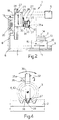
- the disc 32 is keyed to the shaft 35 and, as best, seen in Figure 4, includes a central portion 36 and a peripheral cutting portion 37 which can be resharpened and the half-section of which, defined by a plane passing through the axis of rotation 35a of the disc 32, has a profile 38 ( Figure 4) which is exactly the same as the contour of the teeth of the pinion 3.
- the cutting portion 37 may be made of a material which is highly resistant to wear and thus does not require periodic resharpening.
- the motors 21 and 26 are started in this condition and the disc 32 is moved relative to the table 13, and therefore relative to the gear to be cut, until the aforesaid half-section of the disc 32 is in the same position as a radial section of the pinion 3 defined by a plane perpendicular to the axis 4 of the pinion 3 itself would be in when meshed therewith; in other words, as is shown in Figure 4, the disc 32 is positioned so that the profile 38 is aligned with a cavity, or tooth-spacing, 39 to be cut, that is in a position whereby the profile 38 of the disc would coincide perfectly with the contour of a tooth of the pinion 3 if the pinion 3 were meshed with the gear 2.
- the motors 21, 26 and 30 are actuated simultaneously by the central unit 5 so as to pivot the disc 32 so as to vary its inclination about an axis 40 which is perpendicular to the axis 35a and, in the condition in which the pinion 3 meshed with the gear 2, would coincide with the axis 4 of the pinion 3.
- the motors 15 and 12 are also actuated simultaneously with the motors 21, 26 and 30 so as, respectively, to rotate the table 13, and therefore the gear 2, about the axis 14 and to reciprocate the table 13, and therefore the gear 2, along the line of action 11.
- the motors 21, 26, 30 and 15 are actuated simultaneously in such a way that the ratio between the speed of pivoting of the disc 32 about the axis 40 and the speed of rotation of the table 13, and therefore of the gear 2, about the axis 14 varies in dependence on the position of the contact zone of the disc 32 with the gear 2 and, in particular, during the working of an intermediate portion of a flank of a tooth of the gear 2, is exactly equal to the transmission ratio resulting from the coupling of the pinion 3 with the gear 2 while it is different from the aforesaid gear ratio, and continuously variable, during the working of tip or base portions of these teeth.
- the correction of the profile of the gear teeth is achieved simply by the continuous adjustment, according to the zone of the tooth which is to be worked (tip, root or central portion) of the ratio of the speed of pivoting of the disc 32 about the axis 40 to the speed of rotation of the table 13, and therefore of the gear to be worked, about the axis 14.
- the above manufacturing technique considerably reduces maintenance costs as it greatly facilitates the resharpening of the disc 32, which must obviously be carried out without altering the profile of the cutting portion 37.
- the manufacturing technique described above enables a high degree of dimensional precision to be achieved as well as excellent finishing of the flanks of the teeth of the gear 2. This is essentially due to the fact that, unlike in the prior art in which the disc is moved axially relative to the gear, in this case the face gear 2 to be worked is moved relative to the disc 32 and this naturally brings a reduction in vibration, both of the support structure of the disc 32 and of the disc itself during work on the gear 2.
Landscapes
- Engineering & Computer Science (AREA)
- Mechanical Engineering (AREA)
- Gears, Cams (AREA)
- Gear Processing (AREA)
- Grinding And Polishing Of Tertiary Curved Surfaces And Surfaces With Complex Shapes (AREA)
Description
Claims (8)
- A method for manufacturing a face gear (2) adapted to mesh with a respective toothed pinion (3) defining its axis (4); the method including the steps of:rotating a gear (2) to be worked about a first axis (14) coincident with an axis of symmetry of the gear (2) itself;providing a disc tool (32) having a peripheral cutting portion (37), the radial half-section of which defined by a plane passing through an axis of rotation (35a) of the disc tool (32) having a cutting profile (38) which is exactly the same as the contour of a radial section of the tooth of the pinion (3) defined by a plane perpendicular to the axis (4) of the pinion (3) ;positioning the disc tool (32) relative to the gear (2) so that the half-section of the peripheral cutting portion (37) is arranged in the position in which, during meshing, the section of the tooth of the pinion (3) would be located;rotating the disc tool (32) about its own axis of rotation (35a);moving the disc tool (32) and the gear (2) to be worked translationally relative to each other along a line of action (11) perpendicular to the axis of rotation (35a) of the disc tool (32), andpivoting the disc tool (32) about a second axis (40) perpendicular to the axis of rotation (35a) of the disc tool (32) itself to vary its inclination to the gear (2), the second axis (40) being positioned so that it would be coincident with the axis (4) of the pinion (3) if the pinion (3) itself were meshed with the gear (2);wherein the rotation of the gear (2) about the first axis (14), the pivoting of the disc tool (32) about the second axis (40) and the translational movement of the disc tool (32) and the gear (2) to be worked relative to each other along the line of action (11) are synchronised and carried out simultaneously during the entire process of forming each tooth spacing of the gear (2) to be worked; andwherein the rotation of the gear (2) about the first axis (14) and the pivoting of the disc tool (32) about the second axis (40) are carried out at respective angular velocities the ratio of which is variable in dependence on the position of the zone of contact of the disc tool (32) with the gear (2).
- A method according to Claim 1, characterised in that the ratio of the angular velocities of the gear (2) about the first axis (14) and of the disc tool (32) about the second axis (40) are equal to a transmission ratio obtainable when the finished gear (2) is meshed with the pinion (3) only and exclusively during the working of intermediate portions of the tooth surfaces of the gear (2).
- A method according to Claim 1 or Claim 2, characterised in that the relative translational movement of the disc tool (32) and the gear (2) to be worked is carried out by moving the gear (2) along the line of action (11).
- A method according to any one of the preceding Claims, characterised in that it includes the step of monitoring the variation in the diameter of the disc tool (32) and of adjusting the position of the axis of rotation (35a) of the disc tool (32) itself relative to the gear (2) accordingly.
- A machine for manufacturing a face gear (2) adapted to mesh with a respective toothed pinion (3) defining its own axis (4), the machine (1) including a table (13) rotatable about a first axis (14) and adapted to retain a gear (2) to be worked arranged with its axis coincident with the first axis (14); a motor-driven cutting head (27) including a motor-driven disc tool (32) rotatable about its own axis (35a); and actuator means (21, 26, 30) for positioning the cutting head (27) and pivoting the disc tool (32) about a second axis (40) perpendicular to the axis of rotation (35a) of the disc tool (32) itself, the second axis (40) being positioned so that it would be coincident with the axis (4) of the pinion (3) when meshing with the gear (2); characterised in that the disc tool (32) includes a peripheral cutting portion (37), the half-section of which defined by a plane passing through the axis of rotation (35a) of the disc tool (32) itself having a cutting profile (38) which is exactly the same as the contour of the teeth of the pinion (3) defined by a plane perpendicular to the axis (4) of the pinion (3) itself; electronic control means (5) being provided for controlling the actuator means (21, 26, 30) to act in such a way that the rotation of the gear (2) about the first axis (14) and the pivoting of the disc tool (32) about the second axis (40) are carried out at respective angular velocities the ratio of which is variable in dependence on the position of the zone of contact of the disc tool (32) with the gear (2).
- A machine according to Claim 5, characterised in that said electronic control means (5) are adapted to control said actuator means (21, 26, 30) so that during the working of an intermediate portion of a flank of a tooth of the gear (2), said ratio of angular velocities is exactly equal to the transmission ratio resulting from the coupling of the pinion (3) with the gear (2), while it is different from said transmission ratio and continuously variable during the working of tip and/or base portions of said flank.
- A machine according to Claim 6, characterised in that it includes first drive means (12) for moving the table (13) towards and away from the disc tool (32) along a first line of action (11) perpendicular to the axis of rotation (35a) of the disc tool (32), and second drive means (15) for rotating the table (13) itself about the first axis (14).
- A machine according to Claim 7, characterised in that the actuator means (21, 26, 30) include third (21) and fourth (26) drive means for moving the disc tool (32) along a second line of action (19) and a third line of action (25) respectively, both perpendicular to the first line of action (11), and additional drive means (30) for rotating the disc tool (32) about an axis (29) perpendicular to the second (19) and third (25) lines of action; The electronic control means (5) controlling all the drive means (12, 15, 21, 26, 30) to act simultaneously and in synchronism.
Applications Claiming Priority (2)
| Application Number | Priority Date | Filing Date | Title |
|---|---|---|---|
| ITTO930964A IT1272087B (en) | 1993-12-17 | 1993-12-17 | METHOD AND MACHINE FOR THE CREATION OF TOOTHED WHEELS. |
| ITTO930964 | 1993-12-17 |
Publications (2)
| Publication Number | Publication Date |
|---|---|
| EP0663256A1 EP0663256A1 (en) | 1995-07-19 |
| EP0663256B1 true EP0663256B1 (en) | 2000-10-11 |
Family
ID=11411946
Family Applications (1)
| Application Number | Title | Priority Date | Filing Date |
|---|---|---|---|
| EP94119174A Expired - Lifetime EP0663256B1 (en) | 1993-12-17 | 1994-12-05 | A method and a machine for manufacturing crown or face gears |
Country Status (6)
| Country | Link |
|---|---|
| US (1) | US5562372A (en) |
| EP (1) | EP0663256B1 (en) |
| JP (1) | JPH07285024A (en) |
| DE (1) | DE69426111T2 (en) |
| ES (1) | ES2151917T3 (en) |
| IT (1) | IT1272087B (en) |
Families Citing this family (14)
| Publication number | Priority date | Publication date | Assignee | Title |
|---|---|---|---|---|
| DE19619401C1 (en) * | 1996-05-14 | 1997-11-27 | Reishauer Ag | Method and appliance for profiling grinding worms |
| NL1004338C2 (en) * | 1996-10-23 | 1998-04-24 | Crown Gear Holding B V | Crown wheel shaping machine |
| JP4191336B2 (en) * | 1999-09-13 | 2008-12-03 | ブイアイブイエンジニアリング株式会社 | Manufacturing method of gear case |
| CA2460164A1 (en) * | 2001-09-17 | 2003-03-27 | Gregory Aaron Hyatt | Apparatus and methods for producing a curved tooth |
| DE10162823A1 (en) * | 2001-12-14 | 2003-08-28 | Gleason Pfauter Maschinenfabri | Process for machining essentially cylindrical, internally or externally toothed gears |
| DE10335756A1 (en) * | 2003-08-05 | 2005-03-10 | Guenter Kownatzki | Tool for machining the flat teeth of a crown wheel |
| CN100443229C (en) * | 2005-12-15 | 2008-12-17 | 天津第一机床总厂 | Digital control tooth crest chamfering machine for curved tooth and angle gear |
| JP2009220196A (en) * | 2008-03-13 | 2009-10-01 | Kanzaki Kokyukoki Mfg Co Ltd | Gear working device |
| WO2011017301A1 (en) * | 2009-08-03 | 2011-02-10 | The Gleason Works | Method and tool for manufaturing face gears |
| JP2011115908A (en) * | 2009-12-04 | 2011-06-16 | Mitsubishi Heavy Ind Ltd | Gear processing machine |
| EP2528705B1 (en) * | 2010-01-29 | 2013-10-23 | The Gleason Works | Continuous method for manufacturing face gears |
| US9067269B2 (en) * | 2011-10-13 | 2015-06-30 | Bourn & Koch, Inc. | Horizontal gear shaping machine with dual shaping heads |
| CN104096921B (en) * | 2013-04-12 | 2016-10-12 | 北京广宇大成数控机床有限公司 | Digital control vertical curved-tooth end toothed disc gear grinding machines |
| US9764401B2 (en) * | 2015-05-06 | 2017-09-19 | Caterpillar Inc. | Zero lead generative cutting tool |
Family Cites Families (6)
| Publication number | Priority date | Publication date | Assignee | Title |
|---|---|---|---|---|
| US2304586A (en) * | 1940-12-14 | 1942-12-08 | Fellows Gear Shaper Co | Hob for generating crown gears |
| DE886090C (en) * | 1948-01-13 | 1953-08-10 | Willi Graf | Machine for grinding gears with only partially involute-shaped tooth profiles using the rolling process |
| DE1096718B (en) * | 1948-03-01 | 1961-01-05 | Fellows Gear Shaper Co | Process for the production of crown wheels or plan wheels |
| US4565474A (en) * | 1980-11-01 | 1986-01-21 | The Ingersoll Milling Machine Company | Method of generating involute tooth forms with a milling cutter |
| NL8800472A (en) * | 1988-02-24 | 1989-09-18 | Hankamp Bv | METHOD FOR MANUFACTURING AND / OR FINISHING CROWN WHEELS. |
| DE3915976C2 (en) * | 1989-05-17 | 2002-01-31 | Pfauter Hermann Gmbh Co | Process for finishing the flanks of straight or helical toothed, internally or externally toothed cylindrical wheels by skiving and skiving machine for performing such a method |
-
1993
- 1993-12-17 IT ITTO930964A patent/IT1272087B/en active IP Right Grant
-
1994
- 1994-12-05 ES ES94119174T patent/ES2151917T3/en not_active Expired - Lifetime
- 1994-12-05 DE DE69426111T patent/DE69426111T2/en not_active Expired - Fee Related
- 1994-12-05 EP EP94119174A patent/EP0663256B1/en not_active Expired - Lifetime
- 1994-12-08 US US08/351,839 patent/US5562372A/en not_active Expired - Fee Related
- 1994-12-19 JP JP6315275A patent/JPH07285024A/en active Pending
Also Published As
| Publication number | Publication date |
|---|---|
| ES2151917T3 (en) | 2001-01-16 |
| ITTO930964A0 (en) | 1993-12-17 |
| US5562372A (en) | 1996-10-08 |
| DE69426111D1 (en) | 2000-11-16 |
| JPH07285024A (en) | 1995-10-31 |
| ITTO930964A1 (en) | 1995-06-17 |
| DE69426111T2 (en) | 2001-05-10 |
| IT1272087B (en) | 1997-06-11 |
| EP0663256A1 (en) | 1995-07-19 |
Similar Documents
| Publication | Publication Date | Title |
|---|---|---|
| EP0663256B1 (en) | A method and a machine for manufacturing crown or face gears | |
| JP2550038B2 (en) | Method for grinding teeth of a bevel gear pair with helical teeth and apparatus for carrying out this method | |
| US4765095A (en) | Method for grinding pregeared bevel gears | |
| JPH1058292A (en) | Contour forming method for continuous roller grinding worm and tool and device for use in it | |
| HU185145B (en) | Method and apparatus for machining worm-shaped pieces with worm-shaped tool | |
| JP7224109B2 (en) | Gear manufacturing machining method for workpiece | |
| US9573210B2 (en) | Gear cutting machine, end mill and method of form milling | |
| US4585377A (en) | Numerical-controlled machine tool | |
| KR20110104528A (en) | Machine tool and method for producing gearing | |
| CS277172B6 (en) | Method of cutting a spur gear and apparatus for making the same | |
| EP0330289B1 (en) | A process for the making and/or finishing of crown wheels | |
| JP4664029B2 (en) | Creation method and machine for spiral bevel gears | |
| US3362059A (en) | Gear rolling dies and method for manufacturing external tooth gears | |
| US5014467A (en) | Method and machine for the discontinuous generating grinding with indexing | |
| CN104785830A (en) | Direct-driven zero-drive complete-numerical-control spline shaft milling machine | |
| CN210967319U (en) | 4-axis numerical control involute spline milling machine | |
| JPS624556A (en) | Method of molding outer circumferential surface of work | |
| JP3917844B2 (en) | Cutting gears on both sides | |
| US7562549B2 (en) | Device and method for producing tooth-like profiled sections on workpieces | |
| US2913962A (en) | Gear cutting machine and method and cutter therefor | |
| GB2106436A (en) | Method of and apparatus for gear cutting | |
| GB2153271A (en) | Method and apparatus for producing and machining toothed wheels | |
| US2863360A (en) | Machine and method for producing gears | |
| US4717293A (en) | Method for chamfering the axially facing ends of toothed workpieces, a meshing engagement aid manufactured according to this method, and an apparatus for performing the method | |
| CN110280983A (en) | A kind of face gear skiving processing method |
Legal Events
| Date | Code | Title | Description |
|---|---|---|---|
| PUAI | Public reference made under article 153(3) epc to a published international application that has entered the european phase |
Free format text: ORIGINAL CODE: 0009012 |
|
| AK | Designated contracting states |
Kind code of ref document: A1 Designated state(s): BE CH DE ES FR GB LI SE |
|
| 17P | Request for examination filed |
Effective date: 19960116 |
|
| 17Q | First examination report despatched |
Effective date: 19980310 |
|
| GRAG | Despatch of communication of intention to grant |
Free format text: ORIGINAL CODE: EPIDOS AGRA |
|
| 17Q | First examination report despatched |
Effective date: 19980310 |
|
| GRAG | Despatch of communication of intention to grant |
Free format text: ORIGINAL CODE: EPIDOS AGRA |
|
| GRAH | Despatch of communication of intention to grant a patent |
Free format text: ORIGINAL CODE: EPIDOS IGRA |
|
| GRAH | Despatch of communication of intention to grant a patent |
Free format text: ORIGINAL CODE: EPIDOS IGRA |
|
| GRAA | (expected) grant |
Free format text: ORIGINAL CODE: 0009210 |
|
| AK | Designated contracting states |
Kind code of ref document: B1 Designated state(s): BE CH DE ES FR GB LI SE |
|
| REG | Reference to a national code |
Ref country code: CH Ref legal event code: NV Representative=s name: ISLER & PEDRAZZINI AG Ref country code: CH Ref legal event code: EP |
|
| REF | Corresponds to: |
Ref document number: 69426111 Country of ref document: DE Date of ref document: 20001116 |
|
| ET | Fr: translation filed | ||
| REG | Reference to a national code |
Ref country code: ES Ref legal event code: FG2A Ref document number: 2151917 Country of ref document: ES Kind code of ref document: T3 |
|
| PLBE | No opposition filed within time limit |
Free format text: ORIGINAL CODE: 0009261 |
|
| STAA | Information on the status of an ep patent application or granted ep patent |
Free format text: STATUS: NO OPPOSITION FILED WITHIN TIME LIMIT |
|
| 26N | No opposition filed | ||
| REG | Reference to a national code |
Ref country code: GB Ref legal event code: IF02 |
|
| REG | Reference to a national code |
Ref country code: GB Ref legal event code: 732E |
|
| REG | Reference to a national code |
Ref country code: CH Ref legal event code: PUE Owner name: AVIO S.P.A. Free format text: FIATAVIO S.P.A.#VIA NIZZA 312#10127 TORINO (IT) -TRANSFER TO- AVIO S.P.A.#VIA I MAGGIO, 99#10040 RIVALTA DI TORINO (IT) |
|
| PGFP | Annual fee paid to national office [announced via postgrant information from national office to epo] |
Ref country code: CH Payment date: 20031128 Year of fee payment: 10 |
|
| PGFP | Annual fee paid to national office [announced via postgrant information from national office to epo] |
Ref country code: GB Payment date: 20031202 Year of fee payment: 10 |
|
| PGFP | Annual fee paid to national office [announced via postgrant information from national office to epo] |
Ref country code: SE Payment date: 20031203 Year of fee payment: 10 |
|
| PGFP | Annual fee paid to national office [announced via postgrant information from national office to epo] |
Ref country code: FR Payment date: 20031208 Year of fee payment: 10 |
|
| PGFP | Annual fee paid to national office [announced via postgrant information from national office to epo] |
Ref country code: ES Payment date: 20031216 Year of fee payment: 10 |
|
| PGFP | Annual fee paid to national office [announced via postgrant information from national office to epo] |
Ref country code: BE Payment date: 20031218 Year of fee payment: 10 |
|
| PGFP | Annual fee paid to national office [announced via postgrant information from national office to epo] |
Ref country code: DE Payment date: 20040224 Year of fee payment: 10 |
|
| REG | Reference to a national code |
Ref country code: ES Ref legal event code: PC2A |
|
| REG | Reference to a national code |
Ref country code: FR Ref legal event code: TP |
|
| PG25 | Lapsed in a contracting state [announced via postgrant information from national office to epo] |
Ref country code: GB Free format text: LAPSE BECAUSE OF NON-PAYMENT OF DUE FEES Effective date: 20041205 |
|
| PG25 | Lapsed in a contracting state [announced via postgrant information from national office to epo] |
Ref country code: SE Free format text: LAPSE BECAUSE OF NON-PAYMENT OF DUE FEES Effective date: 20041206 |
|
| PG25 | Lapsed in a contracting state [announced via postgrant information from national office to epo] |
Ref country code: ES Free format text: LAPSE BECAUSE OF NON-PAYMENT OF DUE FEES Effective date: 20041207 |
|
| PG25 | Lapsed in a contracting state [announced via postgrant information from national office to epo] |
Ref country code: LI Free format text: LAPSE BECAUSE OF NON-PAYMENT OF DUE FEES Effective date: 20041231 Ref country code: CH Free format text: LAPSE BECAUSE OF NON-PAYMENT OF DUE FEES Effective date: 20041231 Ref country code: BE Free format text: LAPSE BECAUSE OF NON-PAYMENT OF DUE FEES Effective date: 20041231 |
|
| BERE | Be: lapsed |
Owner name: *AVIO S.P.A. Effective date: 20041231 |
|
| PG25 | Lapsed in a contracting state [announced via postgrant information from national office to epo] |
Ref country code: DE Free format text: LAPSE BECAUSE OF NON-PAYMENT OF DUE FEES Effective date: 20050701 |
|
| GBPC | Gb: european patent ceased through non-payment of renewal fee |
Effective date: 20041205 |
|
| EUG | Se: european patent has lapsed | ||
| REG | Reference to a national code |
Ref country code: CH Ref legal event code: PL |
|
| PG25 | Lapsed in a contracting state [announced via postgrant information from national office to epo] |
Ref country code: FR Free format text: LAPSE BECAUSE OF NON-PAYMENT OF DUE FEES Effective date: 20050831 |
|
| REG | Reference to a national code |
Ref country code: FR Ref legal event code: ST |
|
| REG | Reference to a national code |
Ref country code: ES Ref legal event code: FD2A Effective date: 20041207 |
|
| BERE | Be: lapsed |
Owner name: *AVIO S.P.A. Effective date: 20041231 |