EP0663193A1 - Artificial hip acetabular cup - Google Patents
Artificial hip acetabular cup Download PDFInfo
- Publication number
- EP0663193A1 EP0663193A1 EP93810891A EP93810891A EP0663193A1 EP 0663193 A1 EP0663193 A1 EP 0663193A1 EP 93810891 A EP93810891 A EP 93810891A EP 93810891 A EP93810891 A EP 93810891A EP 0663193 A1 EP0663193 A1 EP 0663193A1
- Authority
- EP
- European Patent Office
- Prior art keywords
- support
- holding device
- shell
- acetabular cup
- inner shell
- Prior art date
- Legal status (The legal status is an assumption and is not a legal conclusion. Google has not performed a legal analysis and makes no representation as to the accuracy of the status listed.)
- Granted
Links
- 238000000034 method Methods 0.000 claims abstract description 10
- 229920003023 plastic Polymers 0.000 claims abstract description 5
- 239000004033 plastic Substances 0.000 claims abstract description 5
- 239000002184 metal Substances 0.000 claims abstract description 3
- 229910052751 metal Inorganic materials 0.000 claims abstract description 3
- 229910052573 porcelain Inorganic materials 0.000 claims abstract description 3
- 210000003049 pelvic bone Anatomy 0.000 claims description 24
- 210000000988 bone and bone Anatomy 0.000 claims description 15
- 230000035515 penetration Effects 0.000 claims description 7
- 239000002639 bone cement Substances 0.000 description 6
- 101100327917 Caenorhabditis elegans chup-1 gene Proteins 0.000 description 4
- 241000309551 Arthraxon hispidus Species 0.000 description 1
- 239000004698 Polyethylene Substances 0.000 description 1
- RTAQQCXQSZGOHL-UHFFFAOYSA-N Titanium Chemical compound [Ti] RTAQQCXQSZGOHL-UHFFFAOYSA-N 0.000 description 1
- 238000004873 anchoring Methods 0.000 description 1
- 230000015572 biosynthetic process Effects 0.000 description 1
- 239000004568 cement Substances 0.000 description 1
- 238000010276 construction Methods 0.000 description 1
- 230000000694 effects Effects 0.000 description 1
- 230000002349 favourable effect Effects 0.000 description 1
- 210000004394 hip joint Anatomy 0.000 description 1
- 239000007943 implant Substances 0.000 description 1
- 238000002513 implantation Methods 0.000 description 1
- 238000003780 insertion Methods 0.000 description 1
- 230000037431 insertion Effects 0.000 description 1
- 210000002414 leg Anatomy 0.000 description 1
- 239000000463 material Substances 0.000 description 1
- 239000007769 metal material Substances 0.000 description 1
- -1 polyethylene Polymers 0.000 description 1
- 229920000573 polyethylene Polymers 0.000 description 1
- 239000010936 titanium Substances 0.000 description 1
- 229910052719 titanium Inorganic materials 0.000 description 1
Images


Classifications
-
- A—HUMAN NECESSITIES
- A61—MEDICAL OR VETERINARY SCIENCE; HYGIENE
- A61F—FILTERS IMPLANTABLE INTO BLOOD VESSELS; PROSTHESES; DEVICES PROVIDING PATENCY TO, OR PREVENTING COLLAPSING OF, TUBULAR STRUCTURES OF THE BODY, e.g. STENTS; ORTHOPAEDIC, NURSING OR CONTRACEPTIVE DEVICES; FOMENTATION; TREATMENT OR PROTECTION OF EYES OR EARS; BANDAGES, DRESSINGS OR ABSORBENT PADS; FIRST-AID KITS
- A61F2/00—Filters implantable into blood vessels; Prostheses, i.e. artificial substitutes or replacements for parts of the body; Appliances for connecting them with the body; Devices providing patency to, or preventing collapsing of, tubular structures of the body, e.g. stents
- A61F2/02—Prostheses implantable into the body
- A61F2/30—Joints
- A61F2/32—Joints for the hip
- A61F2/34—Acetabular cups
-
- A—HUMAN NECESSITIES
- A61—MEDICAL OR VETERINARY SCIENCE; HYGIENE
- A61F—FILTERS IMPLANTABLE INTO BLOOD VESSELS; PROSTHESES; DEVICES PROVIDING PATENCY TO, OR PREVENTING COLLAPSING OF, TUBULAR STRUCTURES OF THE BODY, e.g. STENTS; ORTHOPAEDIC, NURSING OR CONTRACEPTIVE DEVICES; FOMENTATION; TREATMENT OR PROTECTION OF EYES OR EARS; BANDAGES, DRESSINGS OR ABSORBENT PADS; FIRST-AID KITS
- A61F2/00—Filters implantable into blood vessels; Prostheses, i.e. artificial substitutes or replacements for parts of the body; Appliances for connecting them with the body; Devices providing patency to, or preventing collapsing of, tubular structures of the body, e.g. stents
- A61F2/02—Prostheses implantable into the body
- A61F2/30—Joints
- A61F2002/30001—Additional features of subject-matter classified in A61F2/28, A61F2/30 and subgroups thereof
- A61F2002/30316—The prosthesis having different structural features at different locations within the same prosthesis; Connections between prosthetic parts; Special structural features of bone or joint prostheses not otherwise provided for
- A61F2002/30329—Connections or couplings between prosthetic parts, e.g. between modular parts; Connecting elements
- A61F2002/30433—Connections or couplings between prosthetic parts, e.g. between modular parts; Connecting elements using additional screws, bolts, dowels, rivets or washers e.g. connecting screws
-
- A—HUMAN NECESSITIES
- A61—MEDICAL OR VETERINARY SCIENCE; HYGIENE
- A61F—FILTERS IMPLANTABLE INTO BLOOD VESSELS; PROSTHESES; DEVICES PROVIDING PATENCY TO, OR PREVENTING COLLAPSING OF, TUBULAR STRUCTURES OF THE BODY, e.g. STENTS; ORTHOPAEDIC, NURSING OR CONTRACEPTIVE DEVICES; FOMENTATION; TREATMENT OR PROTECTION OF EYES OR EARS; BANDAGES, DRESSINGS OR ABSORBENT PADS; FIRST-AID KITS
- A61F2/00—Filters implantable into blood vessels; Prostheses, i.e. artificial substitutes or replacements for parts of the body; Appliances for connecting them with the body; Devices providing patency to, or preventing collapsing of, tubular structures of the body, e.g. stents
- A61F2/02—Prostheses implantable into the body
- A61F2/30—Joints
- A61F2002/30001—Additional features of subject-matter classified in A61F2/28, A61F2/30 and subgroups thereof
- A61F2002/30316—The prosthesis having different structural features at different locations within the same prosthesis; Connections between prosthetic parts; Special structural features of bone or joint prostheses not otherwise provided for
- A61F2002/30329—Connections or couplings between prosthetic parts, e.g. between modular parts; Connecting elements
- A61F2002/30476—Connections or couplings between prosthetic parts, e.g. between modular parts; Connecting elements locked by an additional locking mechanism
- A61F2002/30477—Connections or couplings between prosthetic parts, e.g. between modular parts; Connecting elements locked by an additional locking mechanism using sharp protrusions, e.g. spikes, for anchoring into connecting prosthetic part
-
- A—HUMAN NECESSITIES
- A61—MEDICAL OR VETERINARY SCIENCE; HYGIENE
- A61F—FILTERS IMPLANTABLE INTO BLOOD VESSELS; PROSTHESES; DEVICES PROVIDING PATENCY TO, OR PREVENTING COLLAPSING OF, TUBULAR STRUCTURES OF THE BODY, e.g. STENTS; ORTHOPAEDIC, NURSING OR CONTRACEPTIVE DEVICES; FOMENTATION; TREATMENT OR PROTECTION OF EYES OR EARS; BANDAGES, DRESSINGS OR ABSORBENT PADS; FIRST-AID KITS
- A61F2/00—Filters implantable into blood vessels; Prostheses, i.e. artificial substitutes or replacements for parts of the body; Appliances for connecting them with the body; Devices providing patency to, or preventing collapsing of, tubular structures of the body, e.g. stents
- A61F2/02—Prostheses implantable into the body
- A61F2/30—Joints
- A61F2002/30001—Additional features of subject-matter classified in A61F2/28, A61F2/30 and subgroups thereof
- A61F2002/30316—The prosthesis having different structural features at different locations within the same prosthesis; Connections between prosthetic parts; Special structural features of bone or joint prostheses not otherwise provided for
- A61F2002/30329—Connections or couplings between prosthetic parts, e.g. between modular parts; Connecting elements
- A61F2002/30476—Connections or couplings between prosthetic parts, e.g. between modular parts; Connecting elements locked by an additional locking mechanism
- A61F2002/30495—Connections or couplings between prosthetic parts, e.g. between modular parts; Connecting elements locked by an additional locking mechanism using a locking ring
-
- A—HUMAN NECESSITIES
- A61—MEDICAL OR VETERINARY SCIENCE; HYGIENE
- A61F—FILTERS IMPLANTABLE INTO BLOOD VESSELS; PROSTHESES; DEVICES PROVIDING PATENCY TO, OR PREVENTING COLLAPSING OF, TUBULAR STRUCTURES OF THE BODY, e.g. STENTS; ORTHOPAEDIC, NURSING OR CONTRACEPTIVE DEVICES; FOMENTATION; TREATMENT OR PROTECTION OF EYES OR EARS; BANDAGES, DRESSINGS OR ABSORBENT PADS; FIRST-AID KITS
- A61F2/00—Filters implantable into blood vessels; Prostheses, i.e. artificial substitutes or replacements for parts of the body; Appliances for connecting them with the body; Devices providing patency to, or preventing collapsing of, tubular structures of the body, e.g. stents
- A61F2/02—Prostheses implantable into the body
- A61F2/30—Joints
- A61F2002/30001—Additional features of subject-matter classified in A61F2/28, A61F2/30 and subgroups thereof
- A61F2002/30316—The prosthesis having different structural features at different locations within the same prosthesis; Connections between prosthetic parts; Special structural features of bone or joint prostheses not otherwise provided for
- A61F2002/30329—Connections or couplings between prosthetic parts, e.g. between modular parts; Connecting elements
- A61F2002/30476—Connections or couplings between prosthetic parts, e.g. between modular parts; Connecting elements locked by an additional locking mechanism
- A61F2002/305—Snap connection
-
- A—HUMAN NECESSITIES
- A61—MEDICAL OR VETERINARY SCIENCE; HYGIENE
- A61F—FILTERS IMPLANTABLE INTO BLOOD VESSELS; PROSTHESES; DEVICES PROVIDING PATENCY TO, OR PREVENTING COLLAPSING OF, TUBULAR STRUCTURES OF THE BODY, e.g. STENTS; ORTHOPAEDIC, NURSING OR CONTRACEPTIVE DEVICES; FOMENTATION; TREATMENT OR PROTECTION OF EYES OR EARS; BANDAGES, DRESSINGS OR ABSORBENT PADS; FIRST-AID KITS
- A61F2/00—Filters implantable into blood vessels; Prostheses, i.e. artificial substitutes or replacements for parts of the body; Appliances for connecting them with the body; Devices providing patency to, or preventing collapsing of, tubular structures of the body, e.g. stents
- A61F2/02—Prostheses implantable into the body
- A61F2/30—Joints
- A61F2002/30001—Additional features of subject-matter classified in A61F2/28, A61F2/30 and subgroups thereof
- A61F2002/30316—The prosthesis having different structural features at different locations within the same prosthesis; Connections between prosthetic parts; Special structural features of bone or joint prostheses not otherwise provided for
- A61F2002/30535—Special structural features of bone or joint prostheses not otherwise provided for
- A61F2002/30576—Special structural features of bone or joint prostheses not otherwise provided for with extending fixation tabs
- A61F2002/30578—Special structural features of bone or joint prostheses not otherwise provided for with extending fixation tabs having apertures, e.g. for receiving fixation screws
-
- A—HUMAN NECESSITIES
- A61—MEDICAL OR VETERINARY SCIENCE; HYGIENE
- A61F—FILTERS IMPLANTABLE INTO BLOOD VESSELS; PROSTHESES; DEVICES PROVIDING PATENCY TO, OR PREVENTING COLLAPSING OF, TUBULAR STRUCTURES OF THE BODY, e.g. STENTS; ORTHOPAEDIC, NURSING OR CONTRACEPTIVE DEVICES; FOMENTATION; TREATMENT OR PROTECTION OF EYES OR EARS; BANDAGES, DRESSINGS OR ABSORBENT PADS; FIRST-AID KITS
- A61F2/00—Filters implantable into blood vessels; Prostheses, i.e. artificial substitutes or replacements for parts of the body; Appliances for connecting them with the body; Devices providing patency to, or preventing collapsing of, tubular structures of the body, e.g. stents
- A61F2/02—Prostheses implantable into the body
- A61F2/30—Joints
- A61F2002/30001—Additional features of subject-matter classified in A61F2/28, A61F2/30 and subgroups thereof
- A61F2002/30621—Features concerning the anatomical functioning or articulation of the prosthetic joint
- A61F2002/30624—Hinged joint, e.g. with transverse axle restricting the movement
-
- A—HUMAN NECESSITIES
- A61—MEDICAL OR VETERINARY SCIENCE; HYGIENE
- A61F—FILTERS IMPLANTABLE INTO BLOOD VESSELS; PROSTHESES; DEVICES PROVIDING PATENCY TO, OR PREVENTING COLLAPSING OF, TUBULAR STRUCTURES OF THE BODY, e.g. STENTS; ORTHOPAEDIC, NURSING OR CONTRACEPTIVE DEVICES; FOMENTATION; TREATMENT OR PROTECTION OF EYES OR EARS; BANDAGES, DRESSINGS OR ABSORBENT PADS; FIRST-AID KITS
- A61F2/00—Filters implantable into blood vessels; Prostheses, i.e. artificial substitutes or replacements for parts of the body; Appliances for connecting them with the body; Devices providing patency to, or preventing collapsing of, tubular structures of the body, e.g. stents
- A61F2/02—Prostheses implantable into the body
- A61F2/30—Joints
- A61F2002/30001—Additional features of subject-matter classified in A61F2/28, A61F2/30 and subgroups thereof
- A61F2002/30667—Features concerning an interaction with the environment or a particular use of the prosthesis
- A61F2002/3069—Revision endoprostheses
-
- A—HUMAN NECESSITIES
- A61—MEDICAL OR VETERINARY SCIENCE; HYGIENE
- A61F—FILTERS IMPLANTABLE INTO BLOOD VESSELS; PROSTHESES; DEVICES PROVIDING PATENCY TO, OR PREVENTING COLLAPSING OF, TUBULAR STRUCTURES OF THE BODY, e.g. STENTS; ORTHOPAEDIC, NURSING OR CONTRACEPTIVE DEVICES; FOMENTATION; TREATMENT OR PROTECTION OF EYES OR EARS; BANDAGES, DRESSINGS OR ABSORBENT PADS; FIRST-AID KITS
- A61F2/00—Filters implantable into blood vessels; Prostheses, i.e. artificial substitutes or replacements for parts of the body; Appliances for connecting them with the body; Devices providing patency to, or preventing collapsing of, tubular structures of the body, e.g. stents
- A61F2/02—Prostheses implantable into the body
- A61F2/30—Joints
- A61F2/30767—Special external or bone-contacting surface, e.g. coating for improving bone ingrowth
- A61F2/30771—Special external or bone-contacting surface, e.g. coating for improving bone ingrowth applied in original prostheses, e.g. holes or grooves
- A61F2002/30772—Apertures or holes, e.g. of circular cross section
- A61F2002/30784—Plurality of holes
- A61F2002/30785—Plurality of holes parallel
-
- A—HUMAN NECESSITIES
- A61—MEDICAL OR VETERINARY SCIENCE; HYGIENE
- A61F—FILTERS IMPLANTABLE INTO BLOOD VESSELS; PROSTHESES; DEVICES PROVIDING PATENCY TO, OR PREVENTING COLLAPSING OF, TUBULAR STRUCTURES OF THE BODY, e.g. STENTS; ORTHOPAEDIC, NURSING OR CONTRACEPTIVE DEVICES; FOMENTATION; TREATMENT OR PROTECTION OF EYES OR EARS; BANDAGES, DRESSINGS OR ABSORBENT PADS; FIRST-AID KITS
- A61F2220/00—Fixations or connections for prostheses classified in groups A61F2/00 - A61F2/26 or A61F2/82 or A61F9/00 or A61F11/00 or subgroups thereof
- A61F2220/0025—Connections or couplings between prosthetic parts, e.g. between modular parts; Connecting elements
- A61F2220/0041—Connections or couplings between prosthetic parts, e.g. between modular parts; Connecting elements using additional screws, bolts, dowels or rivets, e.g. connecting screws
-
- A—HUMAN NECESSITIES
- A61—MEDICAL OR VETERINARY SCIENCE; HYGIENE
- A61F—FILTERS IMPLANTABLE INTO BLOOD VESSELS; PROSTHESES; DEVICES PROVIDING PATENCY TO, OR PREVENTING COLLAPSING OF, TUBULAR STRUCTURES OF THE BODY, e.g. STENTS; ORTHOPAEDIC, NURSING OR CONTRACEPTIVE DEVICES; FOMENTATION; TREATMENT OR PROTECTION OF EYES OR EARS; BANDAGES, DRESSINGS OR ABSORBENT PADS; FIRST-AID KITS
- A61F2310/00—Prostheses classified in A61F2/28 or A61F2/30 - A61F2/44 being constructed from or coated with a particular material
- A61F2310/00005—The prosthesis being constructed from a particular material
- A61F2310/00011—Metals or alloys
- A61F2310/00023—Titanium or titanium-based alloys, e.g. Ti-Ni alloys
-
- A—HUMAN NECESSITIES
- A61—MEDICAL OR VETERINARY SCIENCE; HYGIENE
- A61F—FILTERS IMPLANTABLE INTO BLOOD VESSELS; PROSTHESES; DEVICES PROVIDING PATENCY TO, OR PREVENTING COLLAPSING OF, TUBULAR STRUCTURES OF THE BODY, e.g. STENTS; ORTHOPAEDIC, NURSING OR CONTRACEPTIVE DEVICES; FOMENTATION; TREATMENT OR PROTECTION OF EYES OR EARS; BANDAGES, DRESSINGS OR ABSORBENT PADS; FIRST-AID KITS
- A61F2310/00—Prostheses classified in A61F2/28 or A61F2/30 - A61F2/44 being constructed from or coated with a particular material
- A61F2310/00005—The prosthesis being constructed from a particular material
- A61F2310/00329—Glasses, e.g. bioglass
- A61F2310/00335—Porcelain
Definitions
- the invention relates to an artificial acetabular cup according to the preamble of claim 1.
- the invention further relates to a method for assembling and aligning the acetabular cup according to the invention.
- a support device for an artificial acetabular cup which comprises a hemispherical support shell which has support tabs with openings on its equatorial edge.
- a support shell is particularly suitable as an implant if the pelvic bone is damaged or severely degenerated at the point that supports the hip joint.
- the pelvic bone often shows such a condition, especially during reoperations.
- the support flaps are adapted to the course of the pelvic bone by plastic deformation, in order then to anchor the support device in the pelvic bone with bone screws running through the support flaps.
- a bone cement is applied, which fills the space between the support shell and the bone tissue and forms a cement bed in the support shell, so that an inner shell can be positioned in the support shell and is held by the hardening bone cement.
- acetabular cup which comprises the known support device and a correspondingly adapted inner cup
- a bone cement is required to anchor the entire acetabular cup.
- the use of bone cement has several disadvantages, including the fact that the pelvic bone can experience excessive damage during a reoperation in unfavorable cases.
- the invention has for its object to provide an acetabular cup which has a support device with a support shell and flexible support flaps and comprises an inner shell which are designed such that the acetabular cup can be implanted without bone cement.
- the subclaims 2 to 8 relate to further advantageous embodiments.
- the invention is further achieved with a method for assembling an inventive acetabular cup according to claim 9.
- the sub-claim 10 relates to a further, advantageous method step.
- the acetabular cup according to the invention comprises a hemispherical support shell, on the equatorial edge of which support flaps with openings for bone screws are arranged.
- the acetabular cup also comprises a hemispherical inner shell which can be inserted into the correspondingly dimensioned, hemispherical support shell.
- the acetabular cup further comprises a holding device which can be positioned in front of the opening of the hemispherical cavity of the support shell and which can be firmly connected to the support shell by means of fastening means, so that an inserted inner shell is pretensioned between the Support shell and the holding device is clamped and held thereby.
- the support device according to the invention is preferably anchored in the pelvic bone with bone screws running through the support tabs.
- the support device Before the support device is fastened, it is first placed on the pelvic bone and the support flaps are adapted to the course of the pelvic bone by plastic deformation, so that the support flaps are supported on the pelvic bone and that the underlying bone material is suitable for anchoring with bone screws.
- the adapted support device is then either attached to the pelvic bone with bone screws and the entire acetabular cup is then put together, or the adapted support device is removed again, the entire acetabular cup is put together, and this is attached to the pelvic bone with bone screws running through the support flaps.
- the support device can be designed to be very elastic, and the support device can thus be adapted to the course of the pelvic bone with little effort.
- the entire acetabular cup is given a sufficiently high degree of rigidity.
- Another advantage is the fact that the acetabular cup can be firmly anchored to the pelvic bone without bone cement.
- the outer surface of the inner shell is spherical, and the holding device has a circular recess with protruding teeth, so that the position of the inner shell can be freely positioned in the support shell, and then the circular Recess of the holding device is placed on the outer surface of the inner shell and the holding device is attached to the support device so that the protruding teeth engage in the outer surface and the support device and the inner shell are fixed in a mutually defined position.
- the advantage of this embodiment can be seen in the fact that the position of the inner shell, for example when the support device is already fastened, can be positioned very easily in an orthopedically favorable position and can then be fastened with the holding device. It can prove to be advantageous to provide the inner surface of the support shell with additional penetration elements, such as teeth, which penetrate into the outer surface of the inner shell during the insertion of the inner shell in order to additionally prevent the inner shell from twisting.
- the fastening means of the holding device can be configured, for example, as an abutment and as a latching device.
- the holding device is initially brought into operative connection with the support device such that the connection forms an abutment. Thereafter, the holding device is pivoted towards the support device in a direction defined by the abutment and is firmly connected to the support device by means of a latching device which engages on the support device.
- the holding device can thus be connected to the support device in a very simple manner.
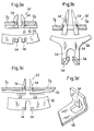
- FIG. 2a shows a bottom view of an exemplary embodiment of an acetabular cup according to the invention, the section (A-A) in FIG. 1 being shown as a side view.
- the support device 1 shows an acetabular cup 1, which comprises a support device 2, an inner shell 3, a holding device 4, and fastening elements 5.
- the support device 2 consists of a hemispherical support shell 2d, on the equatorial edge 2p of which support tabs 2a are arranged.
- the support tabs 2a have openings 2b for receiving bone screws which are to be fastened in the pelvic bone.
- the equatorial edge 2p is surrounded by a protruding edge 2g, 2k which opens into the support tab 2a.
- the support shell 2d has a hemispherical inner surface 2o with a pole 2n and an axis 2m.
- the support shell 2d can have further openings, for example for bone screws or for control openings. Furthermore, a dome may be cut off in the basic region as a hemisphere in the form of a hemisphere, so that the support shell 2d can have larger openings at the pole 2n.
- the support device 2 consists of a metallic material.
- the inner shell 3 serves to receive a joint ball head and is usually made of a plastic, for example of polyethylene. However, the inner shell can also be made from metal, for example from titanium or from a porcelain.
- the inner shell 3 has an inner space 3c which is hemispherical in order to support the ball joint head in an articulated manner.
- the interior 3c has a circular opening 3a, which extends towards the outside to form an outer opening 3b expands.
- the outer surface 3d of the inner shell is adapted to the inner surface 2o of the support shell, the shape of the outer surface 3d advantageously being spherical.
- the inner surface 2o of the support shell 2d can have penetration elements 2e, for example thorns, which penetrate into the outer surface 3d of the inner shell 3 in order to prevent a relative movement between the inner shell 3 and the support device 2.
- a holding device 4 serves to firmly anchor the inner shell 3 in the support shell 2d.
- the holding device 4 is fastened to the supporting device 2 with the fastening means 5 in such a way that the opening 3a, 3b is not covered and in such a way that the holding device 4 has an operative connection to the inner shell 3.
- the fastening means 5 is designed as an abutment on one side and as a latching device 4d on the other side.
- the holding device 4 is designed in its central region as an annular element which has a circular opening 4g with teeth 4f projecting against the interior.
- a snap-in device 4d is arranged on one side as a connecting means, the penetration depth of which is limited by the support elements 4c.
- two support elements 4b are arranged on the circular middle part in such a way that the two support elements 4b enclose the tabs 2a on both sides.
- the support device 2 has a support or a support surface 2c in the region of the equatorial edge 2p, with which the support elements 4d of the holding device 4 can be brought into operative connection, so that an abutment results between the support elements 4b and the support surface 2c.
- the formation of the two support elements 4b requires that the holding device 4 must be threaded onto the tab 2a and the holding device 4 along the tab 2a into it final position can be brought.
- 4 ''' shows a position of a holding device 4 as it can occur during the threading process.
- the acetabular cup 1 according to the invention is implanted by the following method.
- a first step an advantageous position on the pelvic bone is sought for the metallic support device 2, which is characterized in particular by the fact that the support flaps 2a can be positioned in such a way that they rest on the pelvic bone and that the pelvic bone located underneath is suitable for receiving bone screws .
- the metallic support device 2 is thus positioned in an advantageous position on the pelvic bone and the support flap 2a is then plastically deformed in order to adapt its course to the course of the pelvic bone.
- the support device 2 is then lifted off the pelvic bone, removed and the holding device 4 is threaded into the support tab 2.
- the support device is then reinserted into the intended position and fixed to the pelvic bone with bone screws which run through the openings 2b.
- the inner shell 3 is then fitted into the support shell 2d. Since the mutually contacting surfaces of the two shells are spherical, the inner shell 3 can be tilted within wide limits with respect to the supporting shell 2d and rotated relative to one another.
- the inner shell 3 has a gimbal mobility in the support shell 2d. When positioning the support shell 2, the condition of the pelvic bone was particularly taken into account in order to achieve an advantageous fastening of the support device 2 by means of bone screws.
- the cardanic mobility of the inner shell 3 allows the inner shell 3 to be fixed in an orthopedically advantageous position when the inner shell 3 is inserted.
- the inner surface 2o of the support shell 2d has penetration elements 2e, so that the Inner shell 3 must be pressed into the support shell 2 so that the penetration elements 2e penetrate into the outer surface 3d of the inner shell 3.
- a suitable setting instrument can be advantageous in order to press the inner shell 3 into the supporting shell 2d under the action of force.
- the pivotable holding device 4 is pivoted into the position 4 ′′ and further pivoted into the final position 4 ′, the holding device 4 forming an abutment 5 on one side and a latching device on the other side 4d with a latching element 4e, which passes through an opening 2f in the area of the equatorial edge 2g and latches on the surface of the support device 2 facing the pelvic bone.
- the holding device 4 has a circular recess 4g with teeth 4f which, just before the holding device is snapped in, lie in a circle around the outer surfaces 3d of the inner shell 3, so that the teeth 4f penetrate into the surface 3d of the inner shell 3 during further engagement and twist prevent the inner shell 3 in the circumferential direction 4g.
- the inner shell 3 experiences a tension force acting in the direction of the pole 2n, so that the inner shell 3 is held under pretension between the inner surface 2o of the support shell 2d and the holding device 4 when the holding device 4 is engaged.
- the inner shell is thus secured against rotation in the circumferential direction and against movement in the axial direction 2 m.
- the holding device 4 shown, the fastening means 5 of which consists of an abutment and of a latching device 4d, can thus be firmly connected to the supporting device 2 in a simple pivoting movement.
- An advantage of the abutment can be seen in the fact that a lever effect can be achieved with the holding device 4, which can serve to press the inner shell 3 into the supporting shell 2d without a setting instrument.
- FIG. 2b shows a further bottom view of an acetabular cup 1 according to the invention, which comprises a metallic support device 2, an inner shell 3 and a holding device 4 and connecting means 5.
- the construction of the connecting means 5 is identical to the snap-in device shown in FIG. 1, so that the support element 4c and part of the snap-in device 4d of each fastening means 5 can be seen from the bottom view shown in FIG. 2b.
- the holding device 4 is latched and fastened to the support device 2 via the three snap-in devices 4d shown.
- the engagement can take place simultaneously or, as shown in FIG. 1, by a pivoting movement of the holding device 4, in that the holding device 4 is fastened to the support device 2 with one or two locking devices 4d and the third locking device 4d is locked in by a subsequent pivoting movement of the holding device 4 becomes.
- FIG. 2c shows a further embodiment of an acetabular cup 1 according to the invention, consisting of a support device 2, an inner shell 3, a holding device 4 and fastening means 5.
- the fastening means 5 are designed as screws, the heads of which rest on the holding device 4 and their threads engages in a hole made in the support device 2. After inserting the inner shell 3 into the support device 2, the holding device 4 is positioned and fastened to the support device 2 with the screws 5.
- 3a to 3d show different embodiments of snap-in devices.
- 3a shows in side view the protruding edge 2g of the support device 2 with an opening 2f for the Locking device 4d, the penetration depth of which is limited by the supporting element 4b of the holding device 4.
- the latching elements 4e are firmly latched onto the protruding edge 2g of the support device 2.
- the leg length of the latching elements 4e is relatively short, which gives the latching element 4e high rigidity.
- the latching device 4d shown in Fig. 3a thus results in a rather hard connection during the latching process, which is later difficult to solve.
- 3b shows a further latching device 4d with relatively long-legged latching elements 4e, which has the consequence that the latching elements 4e are easier to move against the acting spring force, ie are more elastic, so that this latching device 4d can be opened again relatively easily.
- 3c shows a further exemplary embodiment of a snap-in device 4d, the support element 4b of the holding device 4 being raised in the region of the operative connection 4b 'from the projecting edge of the support device 2g, so that the snap-in elements 4e experience a tensile force vertically to the support device 2g.
- FIG. 4a shows a further embodiment of a latching device 4d.
- the support device 2 has an opening 2f in the area of the protruding edge 2g, immediately following on the equatorial edge 2p, which serves to pass through the latching element 4e.
- the holding device 4 rests with the support element 4c on the underside of the protruding edge 2g, the latching element 4e passes through the recess 2f and engages in the area of the equatorial edge 2p on the outer surface of the support shell 2d.
- FIG. 4b shows a top view of the latching device shown in FIG. 4a.
- FIG. 3d shows a further exemplary embodiment of a latching element 4e with a supporting part 4b, which could take over the holding function instead of the latching device 4d shown in FIG. 4a.
- 5a, 5b, 6a, 6b show two further exemplary embodiments of an abutment.
- 5a shows the tab 2a of the support device 2, which has a T-shaped opening 21 with two contact surfaces 2c.
- 5b shows the support part 4b of the holding device 4, which is introduced into the opening 21 of the flap 2a and which forms an abutment in operative connection with the contact surface 2c.
- 6a shows the tab 2a of a support device 2, which has a U-shaped opening 2l with a bearing surface 2c.
- 6b shows an annular support part 4b of the holding device 4, which rests on the support surface 2c and forms an abutment through this operative connection.
Landscapes
- Health & Medical Sciences (AREA)
- Orthopedic Medicine & Surgery (AREA)
- Cardiology (AREA)
- Oral & Maxillofacial Surgery (AREA)
- Transplantation (AREA)
- Engineering & Computer Science (AREA)
- Biomedical Technology (AREA)
- Heart & Thoracic Surgery (AREA)
- Vascular Medicine (AREA)
- Life Sciences & Earth Sciences (AREA)
- Animal Behavior & Ethology (AREA)
- General Health & Medical Sciences (AREA)
- Public Health (AREA)
- Veterinary Medicine (AREA)
- Prostheses (AREA)
Abstract
Description
Die Erfindung bezieht sich auf eine künstliche Hüftgelenkpfanne gemäss dem Oberbegriff von Anspruch 1. Die Erfindung bezieht sich weiter auf ein Verfahren zum Zusammenstellen sowie zum Ausrichten der erfindungsgemässen Hüftgelenkpfanne.The invention relates to an artificial acetabular cup according to the preamble of claim 1. The invention further relates to a method for assembling and aligning the acetabular cup according to the invention.
Aus der EP-A-0563503 ist eine Stützvorrichtung für eine künstliche Hüftgelenkpfanne bekannt, die eine halbkugelförmige Stützschale umfasst, welche an ihrem äquatorialen Rand Stützlappen mit Durchbrechungen aufweist. Eine solche Stützschale eignet sich insbesondere dann als Implantat, wenn der Beckenknochen an der das Hüftgelenk tragenden Stelle beschädigt oder stark degeneriert ist. Der Beckenknochen weist insbesondere bei Reoperationen häufig einen solchen Zustand auf. Während dem Implantieren der bekannten Stützvorrichtung werden die Stützlappen durch plastische Deformation dem Verlauf des Beckenknochens angepasst um daraufhin die Stützvorrichtung mit durch die Stützlappen verlaufenden Knochenschrauben im Beckenknochen zu verankern. Daraufhin wird ein Knochenzement appliziert, der den Zwischenraum zwischen der Stützschale und dem Knochengewebe füllt und in der Stützschale ein Zementbett bildet, sodass eine Innenschale in der Stützschale positionierbar ist und durch den aushärtenden Knochenzement gehalten wird.From EP-A-0563503 a support device for an artificial acetabular cup is known which comprises a hemispherical support shell which has support tabs with openings on its equatorial edge. Such a support shell is particularly suitable as an implant if the pelvic bone is damaged or severely degenerated at the point that supports the hip joint. The pelvic bone often shows such a condition, especially during reoperations. During the implantation of the known support device, the support flaps are adapted to the course of the pelvic bone by plastic deformation, in order then to anchor the support device in the pelvic bone with bone screws running through the support flaps. Then a bone cement is applied, which fills the space between the support shell and the bone tissue and forms a cement bed in the support shell, so that an inner shell can be positioned in the support shell and is held by the hardening bone cement.
Der Nachteil einer Hüftgelenkpfanne, die die bekannte Stützvorrichtung und eine entsprechend angepasste Innenpfanne umfasst, ist darin zu sehen, dass zur Verankerung der gesamten Hüftgelenkpfanne ein Knochenzement erforderlich ist. Die Verwendung von Knochenzement weist bekanntlich mehrere Nachteile auf, unter anderem den, dass der Beckenknochen bei einer Reoperation in ungünstigen Fällen eine übermässige Schädigung erfahren kann.The disadvantage of an acetabular cup, which comprises the known support device and a correspondingly adapted inner cup, can be seen in the fact that a bone cement is required to anchor the entire acetabular cup. As is well known, the use of bone cement has several disadvantages, including the fact that the pelvic bone can experience excessive damage during a reoperation in unfavorable cases.
Der Erfindung liegt die Aufgabe zugrunde, eine Hüftgelenkpfanne zu schaffen, die eine Stützvorrichtung mit Stützschale und flexiblen Stützlappen aufweist sowie eine Innenschale umfasst, die derart ausgestaltet sind, dass die Hüftgelenkpfanne ohne Knochenzement implantierbar ist.The invention has for its object to provide an acetabular cup which has a support device with a support shell and flexible support flaps and comprises an inner shell which are designed such that the acetabular cup can be implanted without bone cement.
Diese Aufgabe wird gelöst gemäss den kennzeichnenden Merkmalen von Anspruch 1. Die Unteransprüche 2 bis 8 beziehen sich auf weitere vorteilhafte Ausführungsformen. Die Erfindung wird weiter gelöst mit einem Verfahren zum Zusammenstellen einer erfindungsgemässen Hüftgelenkpfanne gemäss Anspruch 9. Der Unteranspruch 10 bezieht sich auf einen weiteren, vorteilhaften Verfahrensschritt.This object is achieved according to the characterizing features of claim 1. The
Die erfindungsgemässe Hüftgelenkpfanne umfasst eine halbkugelförmige Stützschale, an deren äquatorialen Rand Stützlappen mit Durchbrechungen für Knochenschrauben angeordnet sind. Weiter umfasst die Hüftgelenkpfanne eine halbkugelförmige Innenschale, die in die entsprechend dimensionierte, halbkugelförmige stützschale einsetzbar ist. Die Hüftgelenkpfanne umfasst weiter eine Haltevorrichtung, die vor der Öffnung des halbkugelförmigen Hohlraumes der Stützschale positionierbar ist, und mittels Befestigungsmittel fest mit der Stützschale verbindbar ist, sodass eine eingesetzte Innenschale unter Vorspannung zwischen der Stützschale und der Haltevorrichtung geklemmt und dadurch gehalten wird.The acetabular cup according to the invention comprises a hemispherical support shell, on the equatorial edge of which support flaps with openings for bone screws are arranged. The acetabular cup also comprises a hemispherical inner shell which can be inserted into the correspondingly dimensioned, hemispherical support shell. The acetabular cup further comprises a holding device which can be positioned in front of the opening of the hemispherical cavity of the support shell and which can be firmly connected to the support shell by means of fastening means, so that an inserted inner shell is pretensioned between the Support shell and the holding device is clamped and held thereby.
Die erfindungsgemässe Stützvorrichtung wird vorzugsweise mit durch die Stützlappen verlaufende Knochenschrauben im Beckenknochen verankert. Vor dem Befestigen der Stützvorrichtung wird diese vorerst derart an den Beckenknochen angelegt und die Stützlappen durch plastische Deformation dem Verlauf des Beckenknochens angepasst, dass die Stützlappen eine Auflage auf dem Beckenknochen finden, und dass das darunter liegende Knochenmaterial sich zur Verankerung mit Knochenschrauben eignet. Daraufhin wird die angepasste Stützvorrichtung entweder mit Knochenschrauben am Beckenknochen befestigt und daraufhin die gesamte Hüftgelenkpfanne zusammengestellt, oder die angepasste Stützvorrichtung wird nochmals herausgenommen, die gesamte Hüftgelenkpfanne zusammengestellt, und diese mit durch die Stützlappen verlaufende Knochenschrauben am Beckenknochen befestigt.The support device according to the invention is preferably anchored in the pelvic bone with bone screws running through the support tabs. Before the support device is fastened, it is first placed on the pelvic bone and the support flaps are adapted to the course of the pelvic bone by plastic deformation, so that the support flaps are supported on the pelvic bone and that the underlying bone material is suitable for anchoring with bone screws. The adapted support device is then either attached to the pelvic bone with bone screws and the entire acetabular cup is then put together, or the adapted support device is removed again, the entire acetabular cup is put together, and this is attached to the pelvic bone with bone screws running through the support flaps.
Ein Vorteil der Erfindung ist darin zu sehen, dass die Stützvorrichtung sehr elastisch ausgebildet sein kann, und die Stützvorrichtung somit mit geringem Kraftaufwand dem Verlauf des Beckenknochens anpassbar ist. Durch das Einspannen der Innenschale zwischen die Haltevorrichtung und die Stützvorrichtung erhält die gesamte Hüftgelenkpfanne eine genügend grosse Steifigkeit. Ein weiterer Vorteil ist somit darin zu sehen, dass die Hüftgelenkpfanne ohne Knochenzement fest mit dem Beckenknochen verankerbar ist.An advantage of the invention can be seen in the fact that the support device can be designed to be very elastic, and the support device can thus be adapted to the course of the pelvic bone with little effort. By clamping the inner shell between the holding device and the supporting device, the entire acetabular cup is given a sufficiently high degree of rigidity. Another advantage is the fact that the acetabular cup can be firmly anchored to the pelvic bone without bone cement.
In einer besonders vorteilhaften Ausführungsform der Hüftgelenkpfanne ist die Aussenfläche der Innenschale kugelförmig ausgebildet, und die Haltevorrichtung weist eine kreisförmige Ausnehmung mit vorstehenden Zähnen auf, sodass die Lage der Innenschale frei in der Stützschale positionierbar ist, und daraufhin die kreisförmige Ausnehmung der Haltevorrichtung auf die Aussenfläche der Innenschale gelegt wird und die Haltevorrichtung an der Stützvorrichtung befestigt wird, sodass die vorstehenden Zähne in der Aussenfläche eingreifen und die Stützvorrichtung und die Innenschale in einer gegenseitig definierten Lage fixiert sind. Der Vorteil dieser Ausführungsform ist darin zu sehen, dass die Stellung der Innenschale, zum Beispiel bei bereits befestigter Stützvorrichtung sehr einfach in eine orthopädisch günstige Lage positionierbar ist, und anschliessend mit der Haltevorrichtung befestigbar ist. Es kann sich als vorteilhaft erweisen, die Innenfläche der Stützschale mit zusätzlichen Eindringelementen wie Zähnen zu versehen, die während dem Einsetzen der Innenschale in die Aussenfläche der Innenschale eindringen, um ein Verdrehen der Innenschale zusätzlich zu verhindern.In a particularly advantageous embodiment of the acetabular cup, the outer surface of the inner shell is spherical, and the holding device has a circular recess with protruding teeth, so that the position of the inner shell can be freely positioned in the support shell, and then the circular Recess of the holding device is placed on the outer surface of the inner shell and the holding device is attached to the support device so that the protruding teeth engage in the outer surface and the support device and the inner shell are fixed in a mutually defined position. The advantage of this embodiment can be seen in the fact that the position of the inner shell, for example when the support device is already fastened, can be positioned very easily in an orthopedically favorable position and can then be fastened with the holding device. It can prove to be advantageous to provide the inner surface of the support shell with additional penetration elements, such as teeth, which penetrate into the outer surface of the inner shell during the insertion of the inner shell in order to additionally prevent the inner shell from twisting.
Ein weiterer Vorteil der Erfindung ist darin zu sehen, dass die Befestigungsmittel der Haltevorrichtung zum Beispiel als ein Widerlager und als eine Einrastvorrichtung ausgestaltbar sind. Dabei wird die Haltevorrichtung vorerst derart mit der Stützvorrichtung in Wirkverbindung gebracht, dass die Verbindung ein Widerlager bildet. Danach wir die Haltevorrichtung in einer durch das Widerlager festgelegte Richtung zur Stützvorrichtung hin geschwenkt und durch eine an der Stützvorrichtung einrastenden Einrastvorrichtung fest mit der Stützvorrichtung verbunden. Die Haltevorrichtung lässt sich somit auf sehr einfache Weise mit der Stützvorrichtung verbinden.Another advantage of the invention is that the fastening means of the holding device can be configured, for example, as an abutment and as a latching device. The holding device is initially brought into operative connection with the support device such that the connection forms an abutment. Thereafter, the holding device is pivoted towards the support device in a direction defined by the abutment and is firmly connected to the support device by means of a latching device which engages on the support device. The holding device can thus be connected to the support device in a very simple manner.
Im folgenden wird die Erfindung anhand von Ausführungsbeispielen beschrieben. Es zeigen:
- Fig. 1
- Einen Längsschnitt durch eine künstliche Hüftgelenkpfanne entlang der Linie (A-A);
- Fig. 2a
- eine Untenansicht einer künstlichen Hüftgelenkpfanne mit einer schwenkbaren Haltevorrichtung;
- Fig. 2b
- eine Untenansicht einer Hüftgelenkpfanne mit einer einrastbaren Haltevorrichtung;
- Fig. 2c
- eine Untenansicht einer Hüftgelenkpfanne mit einer verschraubbaren Haltevorrichtung;
- Fig. 3a
- eine Aufsicht sowie eine Seitenansicht einer Einrastvorrichtung;
- Fig. 3b
- eine Aufsicht sowie eine Seitenansicht einer weiteren Einrastvorrichtung;
- Fig. 3c
- eine Aufsicht sowie eine Seitenansicht einer weiteren Einrastvorrichtung
- Fig. 3d
- eine perspektivische Ansicht einer weiteren Einrastvorrichtung;
- Fig. 4a
- eine Seitenansicht einer Einrastvorrichtung;
- Fig. 4b
- eine Aufsicht der Einrastvorrichtung gemäss Fig. 4a;
- Fig. 5a
- eine Aufsicht eines Stützlappens mit einer Ausnehmung für ein Widerlager;
- Fig. 5b
- eine Seitenansicht eines Befestigungsteil einer Haltevorrichtung, passend zum Widerlager gemäss Fig. 5a;
- Fig. 6a
- eine Aufsicht einer weiteren Ausführungsform eines Stützlappens mit Widerlager;
- Fig. 6b
- eine Seitenansicht eines weiteren Befestigungsteil einer Haltevorrichtung, passend zum Widerlager gemäss Fig. 6a.
- Fig. 1
- A longitudinal section through an artificial acetabular cup along the line (AA);
- Fig. 2a
- a bottom view of an artificial acetabular cup with a pivotable holding device;
- Fig. 2b
- a bottom view of an acetabular cup with a snap-in holding device;
- Fig. 2c
- a bottom view of an acetabular cup with a screwable holding device;
- Fig. 3a
- a top view and a side view of a locking device;
- Fig. 3b
- a top view and a side view of another latching device;
- Fig. 3c
- a top view and a side view of another locking device
- Fig. 3d
- a perspective view of another locking device;
- Fig. 4a
- a side view of a locking device;
- Fig. 4b
- a top view of the latching device according to FIG. 4a;
- Fig. 5a
- a top view of a support tab with a recess for an abutment;
- Fig. 5b
- a side view of a fastening part of a holding device, suitable for the abutment according to FIG. 5a;
- Fig. 6a
- a plan of another embodiment of a support tab with abutment;
- Fig. 6b
- a side view of another fastening part of a holding device, suitable for the abutment according to FIG. 6a.
Fig. 2a zeigt eine Untenansicht eines Ausführungsbeispieles einer erfindungsgemässen Hüftgelenkpfanne, wobei der Schnitt (A-A) in Fig. 1 als einer Seitenansicht dargestellt ist.2a shows a bottom view of an exemplary embodiment of an acetabular cup according to the invention, the section (A-A) in FIG. 1 being shown as a side view.
Fig. 1 zeigt eine Hüftgelenkpfanne 1, die eine Stützvorrichtung 2, eine Innenschale 3, eine Haltevorrichtung 4, sowie Befestigungselemente 5 umfasst. Die Stützvorrichtug 2 besteht aus einer halbkugelförmigen Stützschale 2d, an deren äquatorialem Rand 2p Stützlappen 2a angeordnet sind. Die Stützlappen 2a weisen Durchbrechungen 2b auf zur Aufnahme von Knochenschrauben, die im Beckenknochen zu befestigen sind. Im vorliegenden Ausführungsbeispiel ist der äquatoriale Rand 2p von einem vorstehenden Rand 2g, 2k umgeben, der in die Stützlappen 2a mündet. Die Stützschale 2d weist eine halbkugelförmige Innenfläche 2o auf mit einem Pol 2n und einer Achse 2m. Die Stützschale 2d kann weitere Durchbrechungen aufweisen, z.B. für Knochenschrauben oder für Kontrollöffnungen. Weiter kann an der in ihrer Grundform als Halbkugel ausgebildeten Stützschale 2d im Polbereich eine Kalotte abgeschnitten sein, so dass die Stützschale 2d am Pol 2n eine grössere Oeffnungen aufweisen kann. Die Stützvorrichtung 2 besteht aus einem metallischen Material. Die Innenschale 3 dient zur Aufnahme eines Gelenkkugelkopfes und ist üblicherweise aus einem Kunststoff, z.B. aus Polyäthylen gefertigt. Die Innenschale kann jedoch auch aus Metall, z.B. aus Titan oder aus einem Porzellan gefertigt sein. Die Innenschale 3 weist einen Innenraum 3c auf, der halbkugelförmige ausgebildet ist, um den Kugelgelenkkopf gelenkig zu lagern. Der Innenraum 3c weist eine kreisförmige Oeffnung 3a auf, die sich gegen aussen zu einer äusseren Oeffnung 3b weitet. Die Aussenfläche 3d der Innenschale ist der Innenfläche 2o der Stützschale angepasst, wobei die Form der Aussenfläche 3d vorteilhafterweise kugelförmig ausgebildet ist. Die Innenfläche 2o der Stützschale 2d kann Eindringelemente 2e, z.B. Dornen, aufweisen, die bei eingesetzter Innenschale 3 in deren Aussenfläche 3d eindringen, um eine Relativbewegung zwischen Innenschale 3 und Stützvorrichtung 2 zu verhindern. Eine Haltevorrichtung 4 dient dazu, die Innenschale 3 fest in der Stützschale 2d zu verankern. Dazu wird die Haltevorrichtung 4 bei eingesetzter Innenschale 3 derart mit Befestigungsmittel 5 an der Stützvorrichtung 2 befestigt, dass die Oeffnung 3a, 3b nicht abgedeckt wird und derart, dass die Haltevorrichtung 4 eine Wirkverbindung zur Innenschale 3 aufweist. Im vorliegenden Ausführungsbeispiel ist das Befestigungsmittel 5 auf der einen Seite als Widerlager ausgebildet, auf der anderen Seite als Einrastvorrichtung 4d. Im vorliegenden Ausführungsbeispiel ist die Haltevorrichtung 4 in ihrem mittleren Bereich als ringförmiges Element ausgbildet, das eine kreisförmige Oeffnung 4g aufweist mit gegen den Innenraum vorstehenden Zähnen 4f. An diesem ringförmigen Teil ist auf der einen Seite als Verbindungsmittel eine Einrastvorrichtung 4d angeordnet, deren Eindringtiefe durch die Auflageelemente 4c begrenzt ist. Weiter sind an dem kreisförmigen Mittelteil zwei Abstützelemente 4b angeordnet derart, dass die beiden Abstützelemente 4b die Lappen 2a beidseitig umfassen. Die Stützvorrichtung 2 weist im Bereich des äquatorialen Randes 2p ein Auflager bzw. eine Auflagefläche 2c auf, mit denen die Abstützelemente 4d der Haltevorrichtung 4 in Wirkverbindung gebracht werden können, so dass sich zwischen den Abstützelementen 4b und der Auflagefläche 2c ein Widerlager eribt. Die Ausbildung der beiden Abstützelemente 4b erfordert es, dass die Haltevorrichtung 4 am Lappen 2a eingefädelt werden muss und die Haltevorrichtung 4 entlang dem Lappen 2a in ihre endgültige Position gebracht werden kann. Mit 4''' ist eine Lage einer Haltevorrichtung 4 dargestellt wie sie während des Einfädelvorganges auftreten kann.1 shows an acetabular cup 1, which comprises a
Die erfindungsgemässe Hüftgelenkpfanne 1 wird nach dem folgenden Verfahren implantiert. In einem ersten Schritt wird für die metallische Stützvorrichtung 2 eine vorteilhafte Lage am Beckenknochen gesucht, die sich insbesondere dadurch auszeichnet, dass die Stützlappen 2a derart positionierbar sind, dass sie auf dem Beckenknochen aufliegen und dass der sich darunter befindliche Beckenknochen für die Aufnahme von Knochenschrauben eignet. Somit wird die metallische Stützvorrichtung 2 in einer vorteilhaften Lage am Beckenknochen positioniert und daraufhin die Stützlappen 2a plastisch verformt, um deren Verlauf dem Verlauf des Beckenknochens anzupassen. Daraufhin wird die Stützvorrichtung 2 vom Beckenknochen abgehoben, herausgenommen und die Haltevorrichtung 4 in den Stützlappen 2 eingefädelt. Daraufhin wird die Stützvorrichtung wieder in die vorgesehene Lage eingesetzt und mit Knochenschrauben, die durch die Durchbrechnungen 2b verlaufen, am Beckenknochen fixiert. Daraufhin wird die Innenschale 3 in die Stützschale 2d eingepasst. Da die sich gegenseitig berührenden Oberflächen der beiden Schale kugelförmige ausgebildet sind, lässt sich die Innenschale 3 in weiten Grenzen gegenüber der Stützschale 2d abkippen sowie gegenseitig verdrehen. Die Innenschale 3 weist eine kardanische Beweglichkeit in der Stützschale 2d auf. Bei der Positionierung der Stützschale 2 wurde insbesondere der Zustand des Beckenknochens berücksichtigt, um eine vorteilhafte Befestigung der Stützvorrichtung 2 mittels Knochenschrauben zu erreichen. Die kardanische Beweglichkeit der Innenschale 3 ermöglicht es, beim Einsetzen der Innenschale 3 diese in einer orthopädisch vorteilhaften Position zu fixieren. Im vorliegenden Ausführungsbeispiel weist die Innenfläche 2o der Stützschale 2d Eindringelemente 2e auf, so dass die Innenschale 3 in die Stützschale 2 eingepresst werden muss, damit die Eindringelemente 2e in die Aussenfläche 3d der Innenschale 3 eindringen. Dazu kann ein geeignetes Setzinstrument vorteilhaft sein, um bei vorgegebener Lage der Innenschale 3 diese unter Krafteinwirkung in die Stützschale 2d zu pressen. Daraufhin wird - wie in Fig. 1 dargetellt - die schwenkbare Haltevorrichtung 4 in die Position 4'' geschwenkt und weiter in die endgültige Position 4' geschwenkt, wobei die Haltevorrichtung 4 auf der einen Seite ein Widerlager 5 bildet und auf der anderen Seite eine Einrastvorrichtung 4d mit einem Einrastelement 4e, das durch eine Durchbrechung 2f im Bereich des äquatorialen Randes 2g hindurchtritt und an der dem Beckenknochen zugewandten Oberfläche der Stützvorrichtung 2 einrastet. Die Haltevorrichtung 4 weist eine kreisförmige Ausnehmung 4g mit Zähnen 4f auf, die sich kurz vor dem Einrasten der Haltevorrichtung kreisförmig um die Aussenflächen 3d der Innenschale 3 legen, so dass die Zähne 4f beim weiteren Einrastvorgang in die Oberfläche 3d der Innenschale 3 eindringen und ein Verdrehen der Innenschale 3 in Umfangsrichtung 4g verhindern. Dabei erfährt die Innenschale 3 eine in Richtung des Poles 2n wirkende Spannkraft, so dass die Innenschale 3 bei eingerasteter Haltevorrichtung 4 unter Vorspannung zwischen der Innenfläche 2o der Stützschale 2d und der Haltevorrichtung 4 gehalten ist. Die Innenschale ist somit gegen eine Verdrehung in Umfangsrichtung sowie gegen eine Bewegung in axialer Richtung 2m gesichert. Die dargestellte Haltevorrichtung 4, deren Befestigungsmittel 5 aus einem Widerlager sowie aus einer Einrastvorrichtung 4d besteht, lässt sich somit auf einfache Weise mit einer einzigen Schwenkbewegung fest mit der Stützvorrichtung 2 verbinden. Ein Vorteil des Widerlagers ist darin zu sehen, dass mit der Haltevorrichtung 4 eine Hebelwirkung erzielbar ist, die dazu dienen kann, die Innenschale 3 ohne ein Setzinstrument in die Stützschale 2d zu pressen.The acetabular cup 1 according to the invention is implanted by the following method. In a first step, an advantageous position on the pelvic bone is sought for the
Fig. 2b zeigt eine weitere Untenansicht einer erfindungsgemässen Hüftgelenkpfanne 1, die eine metallische Stützvorrichtung 2, eine Innenschale 3 sowie eine Haltevorrichtung 4 und Verbindungsmittel 5 umfasst. Der Aufbau der Verbindungsmittel 5 ist identisch zu der in Fig. 1 dargestellten Einrastvorrichtung, so dass aus der in Fig. 2b dargestellten Untenansicht von jedem Befestigungsmittel 5 das Auflageelement 4c sowie ein Teil der Einrastvorrichtung 4d sichtbar ist. Nach dem Einfügen der Innenschale 3 in die Stützschale 2d wird die Haltevorrichtung 4 über die drei dargestellten Einrastvorrichtungen 4d an der Stützvorrichtung 2 eingerastet und befestigt. Das Einrasten kann gleichzeitig erfolgen oder, wie in Fig. 1 dargestellt, durch eine Schwenkbewegung der Haltevorrichtung 4, indem die Haltevorrichtung 4 mit ein oder zwei Einrastvorrichtungen 4d an der Stützvorrichtung 2 befestigt wird und die dritte Einrastvorrichtung 4d durch eine anschliessende Schwenkbewegung der Haltevorrichtung 4 eingerastet wird.2b shows a further bottom view of an acetabular cup 1 according to the invention, which comprises a
Fig. 2c zeigt ein weiteres Ausführungsbeispiel einer erfindungsgemässen Hüftgelenkpfanne 1, bestehend aus einer Stützvorrichtung 2, einer Innenschale 3, einer Haltevorrichtung 4 sowie Befestigungsmittel 5. Im dargestellten Ausführungsbeispiel sind die Befestigungsmittel 5 als Schrauben ausgeführt, deren Köpfe auf der Haltevorrichtung 4 aufliegen und deren Gewinde in eine in der Stützvorrichtung 2 angebrachten Bohrung eingreift. Nach dem Einfügen der Innenschale 3 in die Stützvorrichtung 2 wird die Haltevorrichtung 4 positioniert und mit den Schrauben 5 an der Stützvorrichtung 2 befestigt.2c shows a further embodiment of an acetabular cup 1 according to the invention, consisting of a
Die Fig. 3a bis 3d zeigen verschiedene Ausführungsformen von Einrastvorrichtungen. Fig. 3a zeigt in der Seitenansicht den vorstehenden Rand 2g der Stützvorrichtung 2 mit einer Durchbrechung 2f für die Einrastvorrichtung 4d, deren Eindringtiefe durch das Abstützelement 4b der Haltevorrichtung 4 begrenzt ist. Die Einrastelemente 4e sind fest am vorstehenden Rand 2g der Stützvorrichtung 2 eingerastet. Die Schenkelläge der Einrastelemente 4e ist relativ kurz ausgestaltet, was dem Einrastelement 4e eine hohe Steifigkeit verleiht. Die in Fig. 3a dargestellte Einrastvorrichtung 4d ergibt somit eine während des Einrastvorganges eher harte Verbindung, die nachträglich schwerer zu lösen ist. Fig. 3b zeigt eine weitere Einrastvorrichtung 4d mit relativ langschenkligen Einrastelementen 4e, was zur Folge hat, dass die Einrastelmenente 4e entgegen der wirkenden Federkraft leichter beweglich sind, d.h. elastischer sind, so dass diese Einrastvorrichtung 4d relativ einfach wieder geöffnet werden kann. Fig. 3c zeigt ein weiteres Ausführungsbeispiel einer Einrastvorrichtung 4d, wobei das Abstützelement 4b der Haltevorrichtung 4 im Bereich der Wirkverbindung 4b' vom vorstehenden Rand der Stützvorrichtung 2g abgehoben ist, so dass die eingerasteten Einrastelemente 4e eine Zugkraft vertikal zur Stützvorrichtung 2g erfahren.3a to 3d show different embodiments of snap-in devices. 3a shows in side view the protruding
Fig. 4a zeigt eine weitere Ausgestaltung einer Einrastvorrichtung 4d. Die Stützvorrichtung 2 weist im Bereich des vorstehenden Randes 2g, unmittelbar anschliessend am äquatorialen Rand 2p, eine Durchbrechung 2f auf, die zum Durchtritt des Einrastelementes 4e dient. Die Haltevorrichtung 4 liegt mit dem Auflageelement 4c auf der Unterseite des vorstehenden Randes 2g auf, das Einrastelement 4e tritt durch die Ausnehmung 2f und rastet im Bereich des äquatorialen Randes 2p an der Aussenfläche der Stützschale 2d ein.4a shows a further embodiment of a
Fig. 4b zeigt eine Aufsicht der in Fig. 4a dargestellten Einrastvorrichtung.FIG. 4b shows a top view of the latching device shown in FIG. 4a.
Fig. 3d zeigt ein weiteres Ausführungsbeispiel eines Einrastelementes 4e mit Abstützteil 4b, das an Stelle der in Fig. 4a dargestellten Einrastvorrichtung 4d die Haltefunktion übernehmen könnte.FIG. 3d shows a further exemplary embodiment of a
Die Fig. 5a, 5b, 6a, 6b zeigen zwei weitere Ausführungsbeispiele eines Widerlagers. Fig. 5a zeigt den Lappen 2a der Stützvorrichtung 2, der eine T-förmige Durchbrechung 21 mit zwei Auflageflächen 2c aufweist. Fig. 5b zeigt das in die Durchbrechnung 21 des Lappens 2a eingeführte Abstützteil 4b der Haltevorrichtung 4, das mit der Auflagefläche 2c in Wirkverbindung tretend ein Widerlager bildet. Fig. 6a zeigt den Lappen 2a einer Stützvorrichtung 2, der eine U-förmige Durchbrechung 2l mit einer Auflagefläche 2c aufweist. In Fig. 6b ist ein ringförmiges Abstützteil 4b der Haltevorrichtung 4 dargestellt, das auf der Auflagefläche 2c aufliegt und durch diese Wirkverbindung ein Widerlager bildet.5a, 5b, 6a, 6b show two further exemplary embodiments of an abutment. 5a shows the tab 2a of the
Claims (12)
dadurch gekennzeichnet, dass die künstliche Hüftgelenkpfanne (1) ferner eine Haltevorrichtung (4) und mindestens zwei Befestigungsmittel (5) umfasst, und dass die Haltevorrichtung (4) durch die Befestigungsmittel (5) fest mit der Stützvorrichtung (2) verbunden ist, um die Innenschale (3) zwischen der Stützschale (2d) und der Haltevorrichtung (4) einzuspannen.
characterized in that the artificial acetabular cup (1) further comprises a holding device (4) and at least two fastening means (5), and in that the holding device (4) is fixedly connected to the supporting device (2) by the fastening means (5) in order to Clamp the inner shell (3) between the support shell (2d) and the holding device (4).
Priority Applications (3)
| Application Number | Priority Date | Filing Date | Title |
|---|---|---|---|
| EP93810891A EP0663193B1 (en) | 1993-12-20 | 1993-12-20 | Artificial hip acetabular cup |
| DE59309947T DE59309947D1 (en) | 1993-12-20 | 1993-12-20 | Artificial acetabular cup |
| AT93810891T ATE189377T1 (en) | 1993-12-20 | 1993-12-20 | ARTIFICIAL HIP JOINT |
Applications Claiming Priority (1)
| Application Number | Priority Date | Filing Date | Title |
|---|---|---|---|
| EP93810891A EP0663193B1 (en) | 1993-12-20 | 1993-12-20 | Artificial hip acetabular cup |
Publications (2)
| Publication Number | Publication Date |
|---|---|
| EP0663193A1 true EP0663193A1 (en) | 1995-07-19 |
| EP0663193B1 EP0663193B1 (en) | 2000-02-02 |
Family
ID=8215096
Family Applications (1)
| Application Number | Title | Priority Date | Filing Date |
|---|---|---|---|
| EP93810891A Expired - Lifetime EP0663193B1 (en) | 1993-12-20 | 1993-12-20 | Artificial hip acetabular cup |
Country Status (3)
| Country | Link |
|---|---|
| EP (1) | EP0663193B1 (en) |
| AT (1) | ATE189377T1 (en) |
| DE (1) | DE59309947D1 (en) |
Cited By (14)
| Publication number | Priority date | Publication date | Assignee | Title |
|---|---|---|---|---|
| FR2758714A1 (en) * | 1997-01-29 | 1998-07-31 | Euros Sa | Cotyloid prosthesis for hip joint |
| DE19901710A1 (en) * | 1999-01-18 | 2000-07-27 | Martin Imhof | Implantable prosthesis for hip replacement has supporting ring with circular cantilever and acetabular cup fixed coaxially with screw thread |
| FR2798583A1 (en) * | 1999-09-21 | 2001-03-23 | Denis Chambaud | COTYLOIDIAN IMPLANT |
| WO2002039931A1 (en) * | 2000-11-16 | 2002-05-23 | Willi Horber | Joint prosthesis |
| WO2002039932A1 (en) | 2000-11-16 | 2002-05-23 | Willi Horber | Joint prosthesis |
| FR2824258A1 (en) * | 2001-05-04 | 2002-11-08 | Groupe Lepine | Cup implant, for a hip replacement prosthesis, has a dome with an inner cavity in a truncated cone shape to take a structured sliding core of ceramic or polymer material without increasing its dimensions |
| US6749637B1 (en) | 1999-09-24 | 2004-06-15 | Baehler Andre | Endoprosthesis for a shoulder joint |
| WO2005063148A1 (en) | 2003-12-22 | 2005-07-14 | Plus Orthopedics Ag | Joint socket for a hip endoprosthesis |
| WO2007118553A1 (en) * | 2006-04-13 | 2007-10-25 | Smith & Nephew Orthopaedics Ag | Joint socket, in particular for a hip endoprosthesis |
| US7303585B2 (en) | 2000-11-16 | 2007-12-04 | Willi Horber | Endoprosthesis for a shoulder joint |
| US8123815B2 (en) | 2008-11-24 | 2012-02-28 | Biomet Manufacturing Corp. | Multiple bearing acetabular prosthesis |
| WO2012095168A1 (en) | 2011-01-12 | 2012-07-19 | Smith & Nephew Orthopaedics Ag | A socket, in particular an acetabular socket for a hip endoprosthesis |
| US8308810B2 (en) | 2009-07-14 | 2012-11-13 | Biomet Manufacturing Corp. | Multiple bearing acetabular prosthesis |
| US10945849B2 (en) | 2015-11-23 | 2021-03-16 | Jossi Holding Ag | Joint socket implant |
Citations (6)
| Publication number | Priority date | Publication date | Assignee | Title |
|---|---|---|---|---|
| EP0123514A1 (en) * | 1983-04-20 | 1984-10-31 | National Research Development Corporation | Endoprosthetic bone joint devices |
| EP0205132A2 (en) * | 1985-06-08 | 1986-12-17 | GMT Gesellschaft für medizinische Technik mbH | Cup for an artificial hip joint |
| EP0295912A1 (en) * | 1987-06-17 | 1988-12-21 | JOHNSON & JOHNSON ORTHOPAEDICS INC. | Acetabular cup |
| EP0445068A1 (en) * | 1990-03-02 | 1991-09-04 | Gebrüder Sulzer Aktiengesellschaft | Artificial hip cup |
| FR2684544A1 (en) * | 1991-12-04 | 1993-06-11 | Medinov Sa | Acetabular implant |
| EP0563503A1 (en) * | 1992-04-03 | 1993-10-06 | SULZER Medizinaltechnik AG | Outer shell for an artificial acetabular cup |
-
1993
- 1993-12-20 DE DE59309947T patent/DE59309947D1/en not_active Expired - Fee Related
- 1993-12-20 EP EP93810891A patent/EP0663193B1/en not_active Expired - Lifetime
- 1993-12-20 AT AT93810891T patent/ATE189377T1/en not_active IP Right Cessation
Patent Citations (6)
| Publication number | Priority date | Publication date | Assignee | Title |
|---|---|---|---|---|
| EP0123514A1 (en) * | 1983-04-20 | 1984-10-31 | National Research Development Corporation | Endoprosthetic bone joint devices |
| EP0205132A2 (en) * | 1985-06-08 | 1986-12-17 | GMT Gesellschaft für medizinische Technik mbH | Cup for an artificial hip joint |
| EP0295912A1 (en) * | 1987-06-17 | 1988-12-21 | JOHNSON & JOHNSON ORTHOPAEDICS INC. | Acetabular cup |
| EP0445068A1 (en) * | 1990-03-02 | 1991-09-04 | Gebrüder Sulzer Aktiengesellschaft | Artificial hip cup |
| FR2684544A1 (en) * | 1991-12-04 | 1993-06-11 | Medinov Sa | Acetabular implant |
| EP0563503A1 (en) * | 1992-04-03 | 1993-10-06 | SULZER Medizinaltechnik AG | Outer shell for an artificial acetabular cup |
Cited By (22)
| Publication number | Priority date | Publication date | Assignee | Title |
|---|---|---|---|---|
| FR2758714A1 (en) * | 1997-01-29 | 1998-07-31 | Euros Sa | Cotyloid prosthesis for hip joint |
| DE19901710A1 (en) * | 1999-01-18 | 2000-07-27 | Martin Imhof | Implantable prosthesis for hip replacement has supporting ring with circular cantilever and acetabular cup fixed coaxially with screw thread |
| DE19901710C2 (en) * | 1999-01-18 | 2003-11-20 | Intraplant Ag Cham | Implantable prosthesis for acetabular replacement |
| FR2798583A1 (en) * | 1999-09-21 | 2001-03-23 | Denis Chambaud | COTYLOIDIAN IMPLANT |
| EP1086666A1 (en) * | 1999-09-21 | 2001-03-28 | Denis Chambaud | Cotyloidal implant |
| US6749637B1 (en) | 1999-09-24 | 2004-06-15 | Baehler Andre | Endoprosthesis for a shoulder joint |
| US7303585B2 (en) | 2000-11-16 | 2007-12-04 | Willi Horber | Endoprosthesis for a shoulder joint |
| WO2002039931A1 (en) * | 2000-11-16 | 2002-05-23 | Willi Horber | Joint prosthesis |
| WO2002039932A1 (en) | 2000-11-16 | 2002-05-23 | Willi Horber | Joint prosthesis |
| US6818019B2 (en) | 2000-11-16 | 2004-11-16 | Willi Horber | Joint prosthesis |
| FR2824258A1 (en) * | 2001-05-04 | 2002-11-08 | Groupe Lepine | Cup implant, for a hip replacement prosthesis, has a dome with an inner cavity in a truncated cone shape to take a structured sliding core of ceramic or polymer material without increasing its dimensions |
| WO2005063148A1 (en) | 2003-12-22 | 2005-07-14 | Plus Orthopedics Ag | Joint socket for a hip endoprosthesis |
| DE10360390B4 (en) * | 2003-12-22 | 2006-03-23 | Martin Imhof | Joint socket for a hip endoprosthesis |
| DE10360390A1 (en) * | 2003-12-22 | 2005-07-28 | Martin Imhof | Joint socket for a hip endoprosthesis |
| US8801797B2 (en) | 2003-12-22 | 2014-08-12 | Smith And Nephew Orthopaedics Ag | Joint socket for a hip endoprosthesis |
| WO2007118553A1 (en) * | 2006-04-13 | 2007-10-25 | Smith & Nephew Orthopaedics Ag | Joint socket, in particular for a hip endoprosthesis |
| US8123815B2 (en) | 2008-11-24 | 2012-02-28 | Biomet Manufacturing Corp. | Multiple bearing acetabular prosthesis |
| US9445903B2 (en) | 2008-11-24 | 2016-09-20 | Biomet Manufacturing, Llc | Multi-bearing acetabular prosthesis |
| US8308810B2 (en) | 2009-07-14 | 2012-11-13 | Biomet Manufacturing Corp. | Multiple bearing acetabular prosthesis |
| US9445904B2 (en) | 2009-07-14 | 2016-09-20 | Biomet Manufacturing, Llc | Multiple bearing acetabular prosthesis |
| WO2012095168A1 (en) | 2011-01-12 | 2012-07-19 | Smith & Nephew Orthopaedics Ag | A socket, in particular an acetabular socket for a hip endoprosthesis |
| US10945849B2 (en) | 2015-11-23 | 2021-03-16 | Jossi Holding Ag | Joint socket implant |
Also Published As
| Publication number | Publication date |
|---|---|
| DE59309947D1 (en) | 2000-03-09 |
| EP0663193B1 (en) | 2000-02-02 |
| ATE189377T1 (en) | 2000-02-15 |
Similar Documents
| Publication | Publication Date | Title |
|---|---|---|
| DE69029945T2 (en) | Hip prosthesis | |
| EP0340159B1 (en) | Dowel pin for cementless bone implants | |
| DE69624672T2 (en) | spinal implant | |
| DE69311928T2 (en) | Device for tensioning vertebrae of the human spine | |
| DE69609197T2 (en) | INTERMEDIATE SPINE | |
| DE69514019T2 (en) | Device for correcting an injured spine | |
| DE69205595T2 (en) | Bone surgery implant for intervertebral stabilizer. | |
| DE69810913T2 (en) | DEVICE FOR SPINE OSTEOSYTHESIS WITH STOVELY DISPOSED INTERVAL ANCHOR STICK | |
| DE19549426C2 (en) | Intervertebral implant and instrument therefor | |
| DE69636821T2 (en) | CROSS CONNECTION WITH VARIABLE LENGTH AND ANGLE | |
| DE69813807T2 (en) | IMPLANT AS A SPACE HOLDER BETWEEN THE VERBINE BODIES | |
| DE69920467T2 (en) | DEVICE FOR SPINE-STEM OSTEOSYNTHESIS | |
| DE4220215C2 (en) | Implant to fix adjacent vertebrae | |
| EP0654255B1 (en) | Inner socket for acetabular prosthesis | |
| DE3310944C2 (en) | Cup for a joint endoprosthesis | |
| EP0402810B1 (en) | Implantation set | |
| DE8915443U1 (en) | Implant for a spinal osteosynthesis device, especially in traumatology | |
| DE3227984A1 (en) | Device for the production of a tendon butt suture | |
| DE29521456U1 (en) | Orthopedic retention system | |
| DE4330248A1 (en) | Joint prosthesis | |
| EP0554210A1 (en) | Set of parts for an artificial hip acetabular cup | |
| EP0663193A1 (en) | Artificial hip acetabular cup | |
| EP1570810A1 (en) | Partial pelvic endoprothesis | |
| DE3325448A1 (en) | Hip socket endoprosthesis | |
| EP0688546A1 (en) | Artificial acetabular cup |
Legal Events
| Date | Code | Title | Description |
|---|---|---|---|
| PUAI | Public reference made under article 153(3) epc to a published international application that has entered the european phase |
Free format text: ORIGINAL CODE: 0009012 |
|
| AK | Designated contracting states |
Kind code of ref document: A1 Designated state(s): AT CH DE FR GB IT LI |
|
| RBV | Designated contracting states (corrected) |
Designated state(s): AT CH DE FR GB IT LI |
|
| 17P | Request for examination filed |
Effective date: 19951212 |
|
| 17Q | First examination report despatched |
Effective date: 19970602 |
|
| RAP1 | Party data changed (applicant data changed or rights of an application transferred) |
Owner name: SULZER ORTHOPAEDIE AG |
|
| GRAG | Despatch of communication of intention to grant |
Free format text: ORIGINAL CODE: EPIDOS AGRA |
|
| GRAG | Despatch of communication of intention to grant |
Free format text: ORIGINAL CODE: EPIDOS AGRA |
|
| GRAH | Despatch of communication of intention to grant a patent |
Free format text: ORIGINAL CODE: EPIDOS IGRA |
|
| GRAH | Despatch of communication of intention to grant a patent |
Free format text: ORIGINAL CODE: EPIDOS IGRA |
|
| GRAA | (expected) grant |
Free format text: ORIGINAL CODE: 0009210 |
|
| RIN1 | Information on inventor provided before grant (corrected) |
Inventor name: HERMANN, BREIMESSER Inventor name: ROLAND, WILLI Inventor name: WAGNER, HEINZ, PROF. DR. MED. |
|
| AK | Designated contracting states |
Kind code of ref document: B1 Designated state(s): AT CH DE FR GB IT LI |
|
| REF | Corresponds to: |
Ref document number: 189377 Country of ref document: AT Date of ref document: 20000215 Kind code of ref document: T |
|
| REG | Reference to a national code |
Ref country code: CH Ref legal event code: NV Representative=s name: SULZER MANAGEMENT AG Ref country code: CH Ref legal event code: EP |
|
| GBT | Gb: translation of ep patent filed (gb section 77(6)(a)/1977) |
Effective date: 20000202 |
|
| REF | Corresponds to: |
Ref document number: 59309947 Country of ref document: DE Date of ref document: 20000309 |
|
| ITF | It: translation for a ep patent filed | ||
| ET | Fr: translation filed | ||
| PLBE | No opposition filed within time limit |
Free format text: ORIGINAL CODE: 0009261 |
|
| STAA | Information on the status of an ep patent application or granted ep patent |
Free format text: STATUS: NO OPPOSITION FILED WITHIN TIME LIMIT |
|
| 26N | No opposition filed | ||
| PGFP | Annual fee paid to national office [announced via postgrant information from national office to epo] |
Ref country code: GB Payment date: 20011116 Year of fee payment: 9 |
|
| PGFP | Annual fee paid to national office [announced via postgrant information from national office to epo] |
Ref country code: CH Payment date: 20011120 Year of fee payment: 9 |
|
| PGFP | Annual fee paid to national office [announced via postgrant information from national office to epo] |
Ref country code: AT Payment date: 20011203 Year of fee payment: 9 |
|
| PGFP | Annual fee paid to national office [announced via postgrant information from national office to epo] |
Ref country code: DE Payment date: 20011208 Year of fee payment: 9 |
|
| PGFP | Annual fee paid to national office [announced via postgrant information from national office to epo] |
Ref country code: FR Payment date: 20011211 Year of fee payment: 9 |
|
| REG | Reference to a national code |
Ref country code: GB Ref legal event code: IF02 |
|
| PG25 | Lapsed in a contracting state [announced via postgrant information from national office to epo] |
Ref country code: GB Free format text: LAPSE BECAUSE OF NON-PAYMENT OF DUE FEES Effective date: 20021220 Ref country code: AT Free format text: LAPSE BECAUSE OF NON-PAYMENT OF DUE FEES Effective date: 20021220 |
|
| PG25 | Lapsed in a contracting state [announced via postgrant information from national office to epo] |
Ref country code: LI Free format text: LAPSE BECAUSE OF NON-PAYMENT OF DUE FEES Effective date: 20021231 Ref country code: CH Free format text: LAPSE BECAUSE OF NON-PAYMENT OF DUE FEES Effective date: 20021231 |
|
| PG25 | Lapsed in a contracting state [announced via postgrant information from national office to epo] |
Ref country code: DE Free format text: LAPSE BECAUSE OF NON-PAYMENT OF DUE FEES Effective date: 20030701 |
|
| GBPC | Gb: european patent ceased through non-payment of renewal fee |
Effective date: 20021220 |
|
| REG | Reference to a national code |
Ref country code: CH Ref legal event code: PL |
|
| PG25 | Lapsed in a contracting state [announced via postgrant information from national office to epo] |
Ref country code: FR Free format text: LAPSE BECAUSE OF NON-PAYMENT OF DUE FEES Effective date: 20030901 |
|
| REG | Reference to a national code |
Ref country code: FR Ref legal event code: ST |
|
| PG25 | Lapsed in a contracting state [announced via postgrant information from national office to epo] |
Ref country code: IT Free format text: LAPSE BECAUSE OF NON-PAYMENT OF DUE FEES;WARNING: LAPSES OF ITALIAN PATENTS WITH EFFECTIVE DATE BEFORE 2007 MAY HAVE OCCURRED AT ANY TIME BEFORE 2007. THE CORRECT EFFECTIVE DATE MAY BE DIFFERENT FROM THE ONE RECORDED. Effective date: 20051220 |