EP0662731A2 - Cylindrical air cell - Google Patents
Cylindrical air cell Download PDFInfo
- Publication number
- EP0662731A2 EP0662731A2 EP94309312A EP94309312A EP0662731A2 EP 0662731 A2 EP0662731 A2 EP 0662731A2 EP 94309312 A EP94309312 A EP 94309312A EP 94309312 A EP94309312 A EP 94309312A EP 0662731 A2 EP0662731 A2 EP 0662731A2
- Authority
- EP
- European Patent Office
- Prior art keywords
- positive electrode
- cylindrical
- cup
- layer
- disposed
- Prior art date
- Legal status (The legal status is an assumption and is not a legal conclusion. Google has not performed a legal analysis and makes no representation as to the accuracy of the status listed.)
- Granted
Links
Images





Classifications
-
- H—ELECTRICITY
- H01—ELECTRIC ELEMENTS
- H01M—PROCESSES OR MEANS, e.g. BATTERIES, FOR THE DIRECT CONVERSION OF CHEMICAL ENERGY INTO ELECTRICAL ENERGY
- H01M12/00—Hybrid cells; Manufacture thereof
- H01M12/04—Hybrid cells; Manufacture thereof composed of a half-cell of the fuel-cell type and of a half-cell of the primary-cell type
- H01M12/06—Hybrid cells; Manufacture thereof composed of a half-cell of the fuel-cell type and of a half-cell of the primary-cell type with one metallic and one gaseous electrode
-
- H—ELECTRICITY
- H01—ELECTRIC ELEMENTS
- H01M—PROCESSES OR MEANS, e.g. BATTERIES, FOR THE DIRECT CONVERSION OF CHEMICAL ENERGY INTO ELECTRICAL ENERGY
- H01M50/00—Constructional details or processes of manufacture of the non-active parts of electrochemical cells other than fuel cells, e.g. hybrid cells
- H01M50/10—Primary casings; Jackets or wrappings
- H01M50/183—Sealing members
- H01M50/184—Sealing members characterised by their shape or structure
-
- H—ELECTRICITY
- H01—ELECTRIC ELEMENTS
- H01M—PROCESSES OR MEANS, e.g. BATTERIES, FOR THE DIRECT CONVERSION OF CHEMICAL ENERGY INTO ELECTRICAL ENERGY
- H01M50/00—Constructional details or processes of manufacture of the non-active parts of electrochemical cells other than fuel cells, e.g. hybrid cells
- H01M50/10—Primary casings; Jackets or wrappings
- H01M50/183—Sealing members
- H01M50/186—Sealing members characterised by the disposition of the sealing members
-
- H—ELECTRICITY
- H01—ELECTRIC ELEMENTS
- H01M—PROCESSES OR MEANS, e.g. BATTERIES, FOR THE DIRECT CONVERSION OF CHEMICAL ENERGY INTO ELECTRICAL ENERGY
- H01M50/00—Constructional details or processes of manufacture of the non-active parts of electrochemical cells other than fuel cells, e.g. hybrid cells
- H01M50/10—Primary casings; Jackets or wrappings
- H01M50/183—Sealing members
- H01M50/19—Sealing members characterised by the material
- H01M50/193—Organic material
-
- H—ELECTRICITY
- H01—ELECTRIC ELEMENTS
- H01M—PROCESSES OR MEANS, e.g. BATTERIES, FOR THE DIRECT CONVERSION OF CHEMICAL ENERGY INTO ELECTRICAL ENERGY
- H01M50/00—Constructional details or processes of manufacture of the non-active parts of electrochemical cells other than fuel cells, e.g. hybrid cells
- H01M50/10—Primary casings; Jackets or wrappings
- H01M50/183—Sealing members
- H01M50/19—Sealing members characterised by the material
- H01M50/197—Sealing members characterised by the material having a layered structure
-
- Y—GENERAL TAGGING OF NEW TECHNOLOGICAL DEVELOPMENTS; GENERAL TAGGING OF CROSS-SECTIONAL TECHNOLOGIES SPANNING OVER SEVERAL SECTIONS OF THE IPC; TECHNICAL SUBJECTS COVERED BY FORMER USPC CROSS-REFERENCE ART COLLECTIONS [XRACs] AND DIGESTS
- Y02—TECHNOLOGIES OR APPLICATIONS FOR MITIGATION OR ADAPTATION AGAINST CLIMATE CHANGE
- Y02E—REDUCTION OF GREENHOUSE GAS [GHG] EMISSIONS, RELATED TO ENERGY GENERATION, TRANSMISSION OR DISTRIBUTION
- Y02E60/00—Enabling technologies; Technologies with a potential or indirect contribution to GHG emissions mitigation
- Y02E60/10—Energy storage using batteries
Definitions
- This invention relates to a cylindrical air-cell of which top of positive electrode containing electrolyte and cathode active material or sealing of the bottom of said air-cell is made liquid tight.
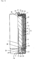
- Fig. 14 shows a partly cutout side view of said air-cell.
- 101 is a cylindrical negative electrode containing an active material of so-called "gelied zinc” in which zinc powder is dispersed in gelied electrolyte
- 102 is a collector provided at the center of negative electrode 101.
- 103 is a multi-layered cylindrical positive electrode comprised of catalyst layer 104 containing manganese oxide and carbon material, collector layer 105 buried within catalyst layer 104, and a water-repellant porous layer 106 made of fluororesin contacted with a surface of catalyst layer 104.
- the other surface of said catalyst layer 104 is faced to negative electrode 102 through separator 107, and is operated by utilizing the oxygen contained in air as an active material.
- 108 is a cylindrical positive electrode-can containing air-diffusing layer 108 made of non-woven fabric covering the surface of said positive electrode 103, and other electricity generating elements including negative electrode 101 and positive electrode 103, and is provided with air-intake hole 110.
- 111 is an insulation tube covering the entire surface of said cylindrical positive electrode can 109, provided with air-intake hole 110 and air-intake window 112 which are connected to said air-intake hole 110.
- 113 is a seal closing said air-intake window 112 and 114 is a resin seal to which the bottom of positive electrode can 109 is bent and clamped.
- 115 is a bottom plate of the negative electrode terminal contacted with collector 102, 116 is a positive electrode cap-terminal contacted with the top of positive electrode 103, 117 is a cell cover, 118 is a grooved part, and 119 is a sealing material preventing the leakage of electrolyte.
- the upper edge of positive electrode 103 is inwardly bent at the rim of grooved part 118, and the bent part is contacted with the rim of positive electrode cap-terminal 116, and these are inserted into cell-cover 117, and the upper edge of positive electrode canister 109 is bent and clamped at the rim of cell-cover 117.
- the lower edge of positive electrode 103 is sealed by inserting the bottom of water repellant porous layer 106 of positive electrode 103 between the sealing body 114 and the positive electrode canister 109, and clamped.
- positive electrode 103 to positive electrode canister 109 is performed by the mechanical contact of positive electrode 103 and positive electrode cap terminal 118 accomplished by the bending of the top rim of positive electrode canister 109, these contacts may become unstable by vibration or shock applied on the cell, making the electric-current supply unstable.
- the purpose of this invention is to offer a new air-cell structure by which the top and bottom of the cylindrical positive electrode consisted of collector and catalyst layers and water-repellant porous layer are sealed liquid tight, preventing the external leakage of electrolyte held within the positive electrode.
- the cylindrical multi-layer positive electrode of the invented air-cell is constituted of a metallic collector, catalyst layers disposed on both sides of said metallic collector, and a porous layer disposed on said catalyst layer wherein an external cup and an internal cup are pressed on the external top rim of said porous layer and internal top rim of catalyst layer of said positive electrode respectively.
- a cylindrical metallic collector layer of which top is inwardly bent can be employed, and said external metal cup pressed on the external top rim of said porous layer and said internal metal cup pressed on the internal top rim of catalyst layer are closely contacted on said inwardly bent part of said metallic collector.
- said cylindrical positive electrode may well be constituted of a gas diffusion layer disposed on the outer surface of said catalyst layer and a porous layer disposed on the outer surface of said gas diffusion layer, and a cap-shaped external metal cup may be pressed on the external top rims of said porous layer and a cap-shaped internal metal cup may be pressed on the internal top rim of said catalyst layer respectively, though said the bent part of said metallic collector may well be held and clamped between said external and internal metal cups.
- a metallic external cup is disposed on the outer top rim of said porous layer, a metallic external cup is disposed on the internal top rim of said catalyst layer of said positive electrode, said positive electrode is inserted in a cylindrical positive electrode canister, and then the said outer metallic cup is welded to said terminal, and the outer rim of said outer cup positioned outside of the welded part of said outer cup and said terminal and the internal surface of said positive electrode canister facing to the outer rim of said outer cup can be electrically insulated.
- a metallic collector layer of which top rim is bent inwardly may be used.
- a resin seal provided with a ring-shaped indentation fitted to the bottom of said positive electrode is used as a bottom seal of said positive electrode.
- the bottom of said positive electrode is inserted in said ring-shaped indentation, and said resin seal is inserted in said positive electrode canister.
- said resin seal provided with a ring-shaped indentation to which the bottom of separator disposed on the positive electrode or on the inner wall of positive electrode is fitted, can be employed.
- said resin seal may well be constituted of two elements, i.e., a seal provided with a ring-shaped indentation fitted to the bottom of said positive electrode or an indentation fitted to both the bottoms of positive electrode and said separator, and an independent seal by which this seal can be held.
- the top of a positive electrode consists of a metallic collector layer, a catalyst layer disposed on the side of said collector layer, and a porous layer held between two metal cups of different inner diameters, and the sides of said metal cups are pressed against said positive electrode, and by this, the top of said positive electrode can be completely sealed without producing cracks or wrinkles possible on said positive electrode so that the leakage or electrolyte from the top of positive electrode can be completely prevented.
- a high electrical conductivity between the positive electrode and the metal cups can be obtained by employing a cylindrical collector layer of which top rim is inwardly bent, and by welding the bent rim to the inner wall of said outer cup, and by pressing said outer cup and inner cup to said bent rim of collector.
- a high electrical conductivity or low internal cell resistance can be obtained by welding the top of said outer cup to the inner wall of said positive electrode canister, preventing contact failures between the collector and the cups even if unexpected shocks or vibration are applied to the cell.
- the bottom of positive electrode can be sealed completely by pressing the bottom of positive electrode against the indentation of resin sealing, and by applying a mechanical pressure on the positive electrode canister at the side of indentation after the bottom of positive electrode is inserted into the indentation of resin seal.
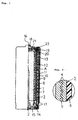
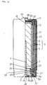
- Fig. 1 shows a side view of the partly cut-off cylindrical zinc air-cell which is a first embodiment of the invention.
- Fig. 2 shows an enlargement of the part-A of Fig. 1.
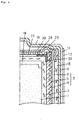
- Fig. 3 shows an enlarged cross-section of the top edge of modified positive electrode of the cylindrical zinc air-cell shown in Fig. 1.
- Fig. 4 shows a top view of the outer cup of cylindrical zinc air-cell shown in Fig. 1.
- Fig. 5 shows a cross-section of the outer cup of cylindrical zinc air-cell shown in Fig. 4, sectioned at Line A-B.
- Fig. 6 shows an enlarged cross-section of the top edge of positive electrode of the cylindrical zinc air-cell which is a second embodiment of the invention.
- Fig. 7 shows a side view of the partly cut-off cylindrical zinc air-cell which is a third embodiment of the invention.
- Fig. 8 shows a side view of the partly cut-off cylindrical zinc air-cell which is a fourth embodiment of the invention.
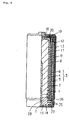
- Fig. 9 shows a side view of the partly cut-off zinc cylindrical air-cell which is a fifth embodiment of the invention.
- Fig. 10 shows a side cross-section of the ring-shaped resin mold employed in the cylindrical air-cell shown in Fig. 9.
- Fig. 11 shows a side view of the partly cut-off modified cylindrical zinc air-cell which is a fifth embodiment of the invention.
- Fig. 12 shows a side view of the partly cut-off cylindrical zinc air-cell which is a sixth embodiment of the invention.
- Fig. 13 shows a side view of the partly cut-off modified cylindrical zinc air-cell which is shown in Fig. 12.
- Fig. 14 shows a side view of the partly cut-off conventional cylindrical zinc air-cell.
- Fig. 1 shows a side view of the partly cut-off cylindrical zinc air-cell which is a first embodiment of the invention
- Fig. 2 shows an enlargement of the part-A of Fig. 1
- Fig. 3 shows an enlarged cross-section of the top end of modified positive electrode of the cylindrical zinc air-cell shown in Fig. 1.
- 1 is a cylindrical negative electrode in which an active material of so-called gelied zinc and collector 2 are incorporated
- 3 is a multilayered cylindrical positive electrode comprised of a catalyst layer 4 employing manganese oxide and carbon materials as main elements
- collector layer 5 consisted of nickel plated stainless steel mesh disposed within catalyst layer 4
- a water-repellant porous layer 6 consisted of fluororesin contacted with a surface of catalyst layer 4
- 7 is a separator disposed within catalyst layer 4 of positive electrode 3 within which negative electrode 1 is disposed
- 8 is an air diffusion layer made of non-woven polypropylene fabric
- 9 is a positive electrode canister on which positive electrode cap terminal 16 is integrally molded at its top
- 10 is an air-intake hole provided on the positive electrode canister 9
- 11 is an insulation tube
- 12 is an air-intake window provided on insulation tube 11
- 13 is a seal sealing the air-intake window until the cell operation
- 14 is a seal made of resin
- 15 is a bottom plate for negative electrode
- the manufacturing process of positive electrode 3, is began with a spot welding process overlapping the both ends of long collector layer forming collector 5 into a cylindrical shape and placing the overlapped part at a surface common with the side surface of collector 5, and a preformed catalyst layer 4 is then pressed on the both surfaces of cylinder-shaped collector 5.
- the material of catalyst layer 4 is prepared by mixing activated carbon, manganese oxide, acetylene-black, and fluororesin powder at a predetermined mixing ratio, and by further kneading of the mixture after a proper amount of ethylalcohol is added. Then, this kneaded mixture is extruded into a strip sheet having a thickness of about 0.6 mm.
- Said manganese oxide is prepared by applying a heat-treatment on ⁇ -MnOOH in a nitrogen atmosphere at a temperature of 400°C, and said fluororesin powder is derived from polytetrafluoroethylene (PTFE) resin.
- PTFE polytetrafluoroethylene
- a fluororesin dispersant containing PTFE resin is coated on a surface of catalyst layer 4 and is dried at a temperature of 230°C.
- the electrolyte can be easily permeated into the electrode, and obstruction of oxygen gas supply to the positive electrode can be prevented.
- the reason of the employment of a drying temperature of 230°C is to disperse the surface active agent contained in the dispersant.
- a gas-permeable water-repellant fluororesin layer is then pressed on the surface coated with fluororesin dispersant in order to obtain porous layer 6 of positive electrode 3 act as an air electrode.
- prepared positive electrode 3 is wound involute in a form of cylinder to face catalyst layer 4 inwardly.
- inner cup 20 and outer cups 19 both made of nickel plated steel plate are disposed on the top of cylindrical positive electrode 3, so that outer cup 19 is contacted with the outer rim while inner cup 20 is contacted with the inner rim of the top edge of said porous layer 5.
- positive electrode 3 can be sealed at a condition where the top edge of positive electrode 3 is held between the outer cup 19 and inner cup 20. Since the outside of outer cup rim is grooved by using a roller and is pressed against the outer surface of positive electrode 3 while inner cup 20 is widened within a space of catalyst layer 4 and pressed against the inner wall of positive electrode 3, positive electrode 3 is held and clamped between the inner cup 20 and the outer cup 19 forming an air-tight and leakage-free sealing.
- the entire inner surface of outer cup 19 is coated with a synthetic rubber sealing material made mainly of chlorosulfonated-polyethylene for example forming a sealing layer 22, in order to improve the air-tightness and leakage-proof performance realizing high reliability of the sealing.
- a synthetic rubber sealing material made mainly of chlorosulfonated-polyethylene for example forming a sealing layer 22, in order to improve the air-tightness and leakage-proof performance realizing high reliability of the sealing.
- small protrusions 23 are disposed on the external top surface of outer cup 19 at three points avoiding a straight line disposition, and these small protrusions 23 are spot-welded on the inner surface of terminal 16 of positive electrode cap, disposed on the top of positive electrode canister 9.
- top of said air-diffusion layer 8 is disposed between the outer rim of outer cup 19 located outside of said small protrusions 23 and the inner side surface of positive electrode canister 9 opposing to these protrusions in order to avoid the contact of outer cup 19 to positive electrode canister 9.
- air diffusion layer 8 covering the outside surface of porous layer 6 and the area from the outer side surface to the top of cup 19 can be formed by using a heat-shrinking porous resin tube made of a resin material such as air-permeable PET or a heat shrinking tube with small openings prepared in advance.
- the bottom edge of positive electrode 3 is formed by bending the bottom edge of positive electrode 9 against the rim of sealing body 14 and by clamping, and by placing the lower edge of porous layer 6 between the sealing body 14 and the positive electrode canister 9 and by filling the gap with a sealing material 17.
- Ten of the cylindrical zinc air-cells A are constructed according to Embodiment-1 shown in Fig. 1, ten conventional cylindrical zinc air-cells C are constructed by bending the top edge of positive electrode inwardly and contacted with the bent part as shown in Fig. 14.
- Ten cylindrical zinc air-cells B are constructed according to Embodiment-1 shown in Fig. 3 but with sealing layer 22 is formed on the inner surface of outer cup 19, and ten conventional cylindrical zinc air-cells D with sealing layer 22 formed at the top edge of positive electrode, are prepared.
- Table 1 Storage Period (at 60°C) Tested cells Sealing applied on outer cup 1 week 2 weeks 3 weeks 1 month Cell A None 2/10 8/10 10/10 - (Fig. 1) Cell B Yes 0/10 0/10 0/10 0/10 (Fig. 3) Cell C None 10/10 - - - (conventional) Cell D Yes 10/10 - - - (conventional)
- the collector of the same function can be obtained by weaving a long horizontal metal thread into a number of independent vertical fine metal wires formed into a shape of cylinder.
- Both the horizontal and vertical metal wires in this case could be nickel plated stainless steel wire or nickel wire, and in this case, erosion of collector by the alkaline electrolyte can be minimized so that the storage characteristics of cell can be improved.
- a bent part 24 formed by bending the top edge inwardly is provided on cylindrical collector 5 as shown in Fig. 6.
- outer cup 19 By pressing and fitting outer cup 19 onto both the upper surface of bent part 24 and the upper edge rim of porous layer 6, and by pressing and fitting the inner cup 20 onto both the lower surface of bent part 24 and the inner rim of upper edge of catalyst layer 4, the bent part 24 can be held and clamped between the inner cup 19 and the outer cup 20. At this condition, outer cup 19 and bent part 24 can be welded together.
- Resin sealing body 14 sealing the bottom of cylindrical positive electrode 3 liquid tight may be provided with a ring-shaped indentation 25 to which the bottom of positive electrode 3 is fitted as shown in Fig. 7. After sealing body 14 provided with indentation 14 to which the bottom of positive electrode is fitted, is inserted into positive electrode canister 9, groove 26 is formed on the side wall of positive electrode canister 9 by applying an external mechanical pressure on sealing body 14.
- sealing body 14 is pressed closely against positive electrode canister 9 and at the same time, the lower edge of positive electrode 3 is fitted liquid tight to indentation 25 of sealing body 14, sealing the bottom of positive electrode 3 completely.
- the sealing condition of the bottom of positive electrode canister can be further improved by applying a sealing agent in a gap between the side of resin sealing body 14 and the side of positive electrode canister.
- the zinc air-cell assembled by using the above-explained sealing body 25 is named as cell F is shown in Fig. 7.
- Ten each cells F and C are assembled and these are submitted to comparative three-month storage tests conducted at a temperature of 60°C testing the leakage from the bottom of positive electrodes 3, and the results are tabulated in Table 3.
- Table 3 Storage Period (at 60°C) Tested cells 10 days 20 days 1 month 2 months 3 months Cell F 0/10 0/10 0/10 0/10 0/10 Cell G 0/10 0/10 0/10 0/10 Cell H 0/10 0/10 0/10 0/10 0/10 Cell I 0/10 0/10 0/10 0/10 0/10 0/10 Conventional 10/10 - - - - Cell C
- resin sealing body 14 may be constituted of a ring-shaped resin mold element 27 provided with indentation 25 to which the bottom of positive electrode 3 is fitted, and a convex resin mold element 28 holding said resin mold element 27.
- cell G The zinc air-cell assembled by employing sealing body 14 of this construction is named as cell G which is an embodiment of the invention and is shown in Fig. 8.
- Table 3 shows a result of the storage test same as the case of Embodiment-3 conducted by using cell G. Likewise, no cell leakage have been found even after three month storage period conducted at a temperature of 60°C.
- metal ring 29 may be disposed between the resin mold element 27 and resin mold body 28 in Embodiment-4.
- the cylindrical air-cell assembled by using the thus constructed sealing body 14 is designated as cell H of Embodiment-5 of the invention, and this is shown in Fig. 9.
- the work to insert the bottom of positive electrode into indentation 25 can be simplified and easier by making the ring-shaped indentation 25 of resin mold element 27 in a form of tapered side-wall 30 which is expanded gradually upward.
- step part 32 By providing step part 32 at the upper part of the inner sidewall of indentation 25 as shown in Fig. 10 in order to hold the lower edge 33 of separator 7, a cell structure shown in Fig. 11 can be obtained, and the possibility of shorts between the positive electrode 3 and the negative electrode 1 can be completely eliminated.
- a cylindrical air-cell of which top edge of positive electrode 3 have a structure shown in Fig. 6 is prepared, and this cell is specified as cell I of Embodiment-6 of the invention here.
- This cell I is submitted to a test same as the previously conducted one, and the result of this is shown in Table 3.
- the resin mold element 28 consists of pillar shaped base 34 and pillar 35 having a diameter smaller than the base 34 disposed on the center of base 34, by providing concave part 36 at a position under base 34 and outer side of pillar 35, and by inserting metal washer 37 therein as shown in Fig. 13, the position of resin mold element 28 can be fixed more tightly when the bottom of positive electrode canister is bent and clamped on the resin mold element 28, and thus the positive electrode canister 9 and the resin mold element can be pressed more tightly.
- a fluororesin porous layer is disposed at the outside of positive electrode 3 in this embodiment of the invention, a better effect can be obtained by employing a gas diffusion layer made of a sheet made of acetylene-black and fluororesin powder improving the oxygen gas supply to positive electrode 3.
- the cylindrical air-cell of the invention consists of a metallic collector layer, a catalyst layer disposed on the side of said metallic collector layer, and a porous layer acting as a cylindrical air electrode disposed on the outside of said catalyst layer, and is provided with an outer metal cup pressed on the outer top edge of said positive electrode and an inner metal cup pressed on the inner top edge of said positive electrode. Since the top of positive electrode is pressed and clamped by said outer and inner cups, the sealing of the top of positive electrode can be substantially improved, offering air-cells having excellent sealing and leak-proof characteristics.
- the contacts between these elements can be held at a best condition, nullifying the possibility of internal resistance increase due to poor contacts between the collector layer and the outer and inner cups.
- a resin mold body having a ring-shaped indentation fitted to the lower edge of positive electrode is disposed at the bottom of positive electrode, and after said resin mold body is inserted into the positive electrode canister, the side of said positive electrode canister is inwardly pressed against the side of said resin mold body in order to improve the sealing between the bottom of positive electrode and the ring-shaped indentation of said resin mold body, thus improving the leak-proof characteristics of the bottom of positive electrode.
Landscapes
- Chemical & Material Sciences (AREA)
- Chemical Kinetics & Catalysis (AREA)
- Electrochemistry (AREA)
- General Chemical & Material Sciences (AREA)
- Engineering & Computer Science (AREA)
- Manufacturing & Machinery (AREA)
- Hybrid Cells (AREA)
- Sealing Battery Cases Or Jackets (AREA)
- Cell Electrode Carriers And Collectors (AREA)
- Inert Electrodes (AREA)
Abstract
Description
- This invention relates to a cylindrical air-cell of which top of positive electrode containing electrolyte and cathode active material or sealing of the bottom of said air-cell is made liquid tight.
- A structure of conventional cylindrical air-cell is explained below by referring Fig. 14 which shows a partly cutout side view of said air-cell. In Fig. 14, 101 is a cylindrical negative electrode containing an active material of so-called "gelied zinc" in which zinc powder is dispersed in gelied electrolyte, and 102 is a collector provided at the center of
negative electrode 101. 103 is a multi-layered cylindrical positive electrode comprised ofcatalyst layer 104 containing manganese oxide and carbon material,collector layer 105 buried withincatalyst layer 104, and a water-repellantporous layer 106 made of fluororesin contacted with a surface ofcatalyst layer 104. - The other surface of said
catalyst layer 104 is faced tonegative electrode 102 throughseparator 107, and is operated by utilizing the oxygen contained in air as an active material. 108 is a cylindrical positive electrode-can containing air-diffusinglayer 108 made of non-woven fabric covering the surface of saidpositive electrode 103, and other electricity generating elements includingnegative electrode 101 andpositive electrode 103, and is provided with air-intake hole 110. 111 is an insulation tube covering the entire surface of said cylindrical positive electrode can 109, provided with air-intake hole 110 and air-intake window 112 which are connected to said air-intake hole 110. - 113 is a seal closing said air-
intake window collector positive electrode - Explaining this cell structure further, the upper edge of
positive electrode 103 is inwardly bent at the rim ofgrooved part 118, and the bent part is contacted with the rim of positive electrode cap-terminal 116, and these are inserted into cell-cover 117, and the upper edge ofpositive electrode canister 109 is bent and clamped at the rim of cell-cover 117. The lower edge ofpositive electrode 103 is sealed by inserting the bottom of water repellantporous layer 106 ofpositive electrode 103 between the sealingbody 114 and thepositive electrode canister 109, and clamped. - By employing the above explained cell-structure, leakage of gelied electrolyte filled within the cylindrical
positive electrode 103 and leakage of electrolyte containing the zinc powder filled in the negative electrode from the top to the bottom end ofpositive electrode canister 109 can be prevented. - However, when the top end of cylindrical
positive electrode 103 consisted ofcollector 105,catalyst layer 104, and water repellantporous layer 106, is bent at a rim ofgroove 118 provided for the sealing, clacks ofcatalyst layer 104 may apt to be produced at the bending or wrinkles of water-repellantporous layer 106 are apt to take place, and as a result of this, complete seal of cell-cover 117 had been hard to accomplish. - Furthermore, since the sealing of bottom edge of
positive electrode canister 109 is performed by clamping only the edge of water repellantporous layer 106 between the sealingbody 114 and thepositive electrode canister 109, clacks of edge of water repellantporous layer 109 are apt to be produced so that perfect seal had been hard to obtain. - Since the alkaline electrolyte has a strong tendency of creeping and leakage through minute wrinkles or cracks of seal if produced, leakage of electrolyte may takes place easily during the storage period or during the usage thereof.
- Moreover, the conduction from
positive electrode 103 topositive electrode canister 109 is performed by the mechanical contact ofpositive electrode 103 and positiveelectrode cap terminal 118 accomplished by the bending of the top rim ofpositive electrode canister 109, these contacts may become unstable by vibration or shock applied on the cell, making the electric-current supply unstable. - The purpose of this invention is to offer a new air-cell structure by which the top and bottom of the cylindrical positive electrode consisted of collector and catalyst layers and water-repellant porous layer are sealed liquid tight, preventing the external leakage of electrolyte held within the positive electrode.
- In order to accomplish the present purposes, the cylindrical multi-layer positive electrode of the invented air-cell is constituted of a metallic collector, catalyst layers disposed on both sides of said metallic collector, and a porous layer disposed on said catalyst layer wherein an external cup and an internal cup are pressed on the external top rim of said porous layer and internal top rim of catalyst layer of said positive electrode respectively.
- Moreover, as a metallic collector constituting said positive electrode, a cylindrical metallic collector layer of which top is inwardly bent can be employed, and said external metal cup pressed on the external top rim of said porous layer and said internal metal cup pressed on the internal top rim of catalyst layer are closely contacted on said inwardly bent part of said metallic collector.
- Likewise, said cylindrical positive electrode may well be constituted of a gas diffusion layer disposed on the outer surface of said catalyst layer and a porous layer disposed on the outer surface of said gas diffusion layer, and a cap-shaped external metal cup may be pressed on the external top rims of said porous layer and a cap-shaped internal metal cup may be pressed on the internal top rim of said catalyst layer respectively, though said the bent part of said metallic collector may well be held and clamped between said external and internal metal cups.
- In another structure of the invented air-cell, a metallic external cup is disposed on the outer top rim of said porous layer, a metallic external cup is disposed on the internal top rim of said catalyst layer of said positive electrode, said positive electrode is inserted in a cylindrical positive electrode canister, and then the said outer metallic cup is welded to said terminal, and the outer rim of said outer cup positioned outside of the welded part of said outer cup and said terminal and the internal surface of said positive electrode canister facing to the outer rim of said outer cup can be electrically insulated. In this case, a metallic collector layer of which top rim is bent inwardly, may be used.
- In the still other structure of the invented air-cell, a resin seal provided with a ring-shaped indentation fitted to the bottom of said positive electrode is used as a bottom seal of said positive electrode. In this case, the bottom of said positive electrode is inserted in said ring-shaped indentation, and said resin seal is inserted in said positive electrode canister. After this, the side of resin seal is so pressed against the opposing inner wall of the positive-electrode canister that the bottom of positive electrode and the indentation of resin seal are contacted closely.
- Moreover, in another structure of the invented air-cell, said resin seal provided with a ring-shaped indentation to which the bottom of separator disposed on the positive electrode or on the inner wall of positive electrode is fitted, can be employed.
- In still another structure of the invented air-cell, said resin seal may well be constituted of two elements, i.e., a seal provided with a ring-shaped indentation fitted to the bottom of said positive electrode or an indentation fitted to both the bottoms of positive electrode and said separator, and an independent seal by which this seal can be held.
- According to the above described explanations, the functions of the inventions are as follows.
- The top of a positive electrode consists of a metallic collector layer, a catalyst layer disposed on the side of said collector layer, and a porous layer held between two metal cups of different inner diameters, and the sides of said metal cups are pressed against said positive electrode, and by this, the top of said positive electrode can be completely sealed without producing cracks or wrinkles possible on said positive electrode so that the leakage or electrolyte from the top of positive electrode can be completely prevented.
- In another case, a high electrical conductivity between the positive electrode and the metal cups can be obtained by employing a cylindrical collector layer of which top rim is inwardly bent, and by welding the bent rim to the inner wall of said outer cup, and by pressing said outer cup and inner cup to said bent rim of collector. Moreover, a high electrical conductivity or low internal cell resistance can be obtained by welding the top of said outer cup to the inner wall of said positive electrode canister, preventing contact failures between the collector and the cups even if unexpected shocks or vibration are applied to the cell.
- Moreover, the bottom of positive electrode can be sealed completely by pressing the bottom of positive electrode against the indentation of resin sealing, and by applying a mechanical pressure on the positive electrode canister at the side of indentation after the bottom of positive electrode is inserted into the indentation of resin seal.
- Furthermore, by inserting the bottom of separator into the indentation of resin seal, not only the excessive stress application on the positive electrode at sealing process can be avoided, but the sealing performance can also be improved. Thus, the leakage of electrolyte and the shorts between the positive and the negative electrodes can be prevented improving the cell reliability further.
- Fig. 1 shows a side view of the partly cut-off cylindrical zinc air-cell which is a first embodiment of the invention.
- Fig. 2 shows an enlargement of the part-A of Fig. 1.
- Fig. 3 shows an enlarged cross-section of the top edge of modified positive electrode of the cylindrical zinc air-cell shown in Fig. 1.
- Fig. 4 shows a top view of the outer cup of cylindrical zinc air-cell shown in Fig. 1.
- Fig. 5 shows a cross-section of the outer cup of cylindrical zinc air-cell shown in Fig. 4, sectioned at Line A-B.
- Fig. 6 shows an enlarged cross-section of the top edge of positive electrode of the cylindrical zinc air-cell which is a second embodiment of the invention.
- Fig. 7 shows a side view of the partly cut-off cylindrical zinc air-cell which is a third embodiment of the invention.
- Fig. 8 shows a side view of the partly cut-off cylindrical zinc air-cell which is a fourth embodiment of the invention.
- Fig. 9 shows a side view of the partly cut-off zinc cylindrical air-cell which is a fifth embodiment of the invention.
- Fig. 10 shows a side cross-section of the ring-shaped resin mold employed in the cylindrical air-cell shown in Fig. 9.
- Fig. 11 shows a side view of the partly cut-off modified cylindrical zinc air-cell which is a fifth embodiment of the invention.
- Fig. 12 shows a side view of the partly cut-off cylindrical zinc air-cell which is a sixth embodiment of the invention.
- Fig. 13 shows a side view of the partly cut-off modified cylindrical zinc air-cell which is shown in Fig. 12.
- Fig. 14 shows a side view of the partly cut-off conventional cylindrical zinc air-cell.
- Fig. 1 shows a side view of the partly cut-off cylindrical zinc air-cell which is a first embodiment of the invention, Fig. 2 shows an enlargement of the part-A of Fig. 1, and Fig. 3 shows an enlarged cross-section of the top end of modified positive electrode of the cylindrical zinc air-cell shown in Fig. 1.
- In Figs. 1 to 3, 1 is a cylindrical negative electrode in which an active material of so-called gelied zinc and
collector 2 are incorporated, 3 is a multilayered cylindrical positive electrode comprised of acatalyst layer 4 employing manganese oxide and carbon materials as main elements,collector layer 5 consisted of nickel plated stainless steel mesh disposed withincatalyst layer 4, and a water-repellantporous layer 6 consisted of fluororesin contacted with a surface ofcatalyst layer catalyst layer 4 ofpositive electrode 3, within whichnegative electrode 1 is disposed, 8 is an air diffusion layer made of non-woven polypropylene fabric, 9 is a positive electrode canister on which positiveelectrode cap terminal 16 is integrally molded at its top, 10 is an air-intake hole provided on thepositive electrode canister insulation tube - The manufacturing process of
positive electrode 3, is began with a spot welding process overlapping the both ends of long collectorlayer forming collector 5 into a cylindrical shape and placing the overlapped part at a surface common with the side surface ofcollector 5, and apreformed catalyst layer 4 is then pressed on the both surfaces of cylinder-shaped collector 5. - The material of
catalyst layer 4 is prepared by mixing activated carbon, manganese oxide, acetylene-black, and fluororesin powder at a predetermined mixing ratio, and by further kneading of the mixture after a proper amount of ethylalcohol is added. Then, this kneaded mixture is extruded into a strip sheet having a thickness of about 0.6 mm. Said manganese oxide is prepared by applying a heat-treatment on γ-MnOOH in a nitrogen atmosphere at a temperature of 400°C, and said fluororesin powder is derived from polytetrafluoroethylene (PTFE) resin. Granulated or chained activated carbon having a particle diameter of 10 to 40 microns is used in this case. - On the other hand, a fluororesin dispersant containing PTFE resin is coated on a surface of
catalyst layer 4 and is dried at a temperature of 230°C. By this, the electrolyte can be easily permeated into the electrode, and obstruction of oxygen gas supply to the positive electrode can be prevented. The reason of the employment of a drying temperature of 230°C is to disperse the surface active agent contained in the dispersant. - A gas-permeable water-repellant fluororesin layer is then pressed on the surface coated with fluororesin dispersant in order to obtain
porous layer 6 ofpositive electrode 3 act as an air electrode. Thus preparedpositive electrode 3 is wound involute in a form of cylinder to facecatalyst layer 4 inwardly. - Then,
inner cup 20 andouter cups 19 both made of nickel plated steel plate are disposed on the top of cylindricalpositive electrode 3, so thatouter cup 19 is contacted with the outer rim whileinner cup 20 is contacted with the inner rim of the top edge of saidporous layer 5. As a result of this,positive electrode 3 can be sealed at a condition where the top edge ofpositive electrode 3 is held between theouter cup 19 andinner cup 20. Since the outside of outer cup rim is grooved by using a roller and is pressed against the outer surface ofpositive electrode 3 whileinner cup 20 is widened within a space ofcatalyst layer 4 and pressed against the inner wall ofpositive electrode 3,positive electrode 3 is held and clamped between theinner cup 20 and theouter cup 19 forming an air-tight and leakage-free sealing. - Furthermore, as shown in Fig. 3, the entire inner surface of
outer cup 19 is coated with a synthetic rubber sealing material made mainly of chlorosulfonated-polyethylene for example forming asealing layer 22, in order to improve the air-tightness and leakage-proof performance realizing high reliability of the sealing. - Thus, after sealing the top of
positive electrode 3, the external surface ofporous layer 6 and the area from the outer rim ofouter cup 19 to the upper round-off part are wrapped by air-diffusion layer 8. - As shown in Figs. 4 and 5,
small protrusions 23 are disposed on the external top surface ofouter cup 19 at three points avoiding a straight line disposition, and thesesmall protrusions 23 are spot-welded on the inner surface ofterminal 16 of positive electrode cap, disposed on the top ofpositive electrode canister 9. - Moreover, the top of said air-
diffusion layer 8 is disposed between the outer rim ofouter cup 19 located outside of saidsmall protrusions 23 and the inner side surface ofpositive electrode canister 9 opposing to these protrusions in order to avoid the contact ofouter cup 19 topositive electrode canister 9. - By employing the above-described cell construction, since the eddy current produced at welding of small protrusions onto the top inner surface of
positive electrode canister 9 is concentrated only to the small protrusions ofouter cup 19, a higher welding strength and better appearance welding between thepositive electrode canister 9 and the small protrusions can be obtained. Moreover, because of anopening 21 provided on the top center ofinner cup 20, a welding rod can be inserted throughopening 21 whenpositive electrode canister 9 is welded to theouter cup 19 so that the welding bar can be contacted withouter cup 19 and the welding of these components can be performed easily at a better stabilized condition. - Furthermore, instead of the non-woven fabric,
air diffusion layer 8 covering the outside surface ofporous layer 6 and the area from the outer side surface to the top ofcup 19 can be formed by using a heat-shrinking porous resin tube made of a resin material such as air-permeable PET or a heat shrinking tube with small openings prepared in advance. - The bottom edge of
positive electrode 3 is formed by bending the bottom edge ofpositive electrode 9 against the rim of sealingbody 14 and by clamping, and by placing the lower edge ofporous layer 6 between the sealingbody 14 and thepositive electrode canister 9 and by filling the gap with a sealingmaterial 17. - Ten of the cylindrical zinc air-cells A are constructed according to Embodiment-1 shown in Fig. 1, ten conventional cylindrical zinc air-cells C are constructed by bending the top edge of positive electrode inwardly and contacted with the bent part as shown in Fig. 14. Ten cylindrical zinc air-cells B are constructed according to Embodiment-1 shown in Fig. 3 but with sealing
layer 22 is formed on the inner surface ofouter cup 19, and ten conventional cylindrical zinc air-cells D with sealinglayer 22 formed at the top edge of positive electrode, are prepared. - The storage characteristics of these cells are comparatively tested at a storage temperature of 60°C and the result of these are shown in Table 1.
Table 1 Storage Period (at 60°C) Tested cells Sealing applied on outer cup 1 week 2 weeks 3 weeks 1 month Cell A None 2/10 8/10 10/10 - (Fig. 1) Cell B Yes 0/10 0/10 0/10 0/10 (Fig. 3) Cell C None 10/10 - - - (conventional) Cell D Yes 10/10 - - - (conventional) - As shown in Table 1, the conventional zinc air-cells C and D showed very severe electrolyte leakages within very short periods, regardless the coating of sealing material.
- On the other hand, none of the zinc air-cells B of Embodiment-1 showed leakage after a storage period of one month at 60°C while all of the zinc air-cells A showed leakage after a storage period of three weeks.
- Therefore, significant improvements of leakage stopping characteristics obtained by the invented zinc air-cells over those of conventional zinc air-cells are confirmed, in addition to further improvements obtained with sealing
layer 22 formed on the internal surface ofouter cup 19. - However, when the width of overlapped region of the cylindrically formed collector is inadequate, an insufficient tensile strength of the overlapped region would be produced.
- Therefore, when a volume expansion of the zinc
negative electrode 1 is produced at discharge, breakage of welded points at the edges of collector may takes place, causing electrolyte leakage. Thus, at least an overlap width of 1.3 % of the circumference ofcollector layer 5 have to be provided. - On the other hand, when said overlapped width is too large, the collector area providing minute holes are plugged, sacrificing the discharge capacity somewhat. The sacrifice of discharge capacity can be minimized by setting the overlapped width at less than 9% of the total circumference of
collector layer 5. - Although a case where the both ends of long stainless steel mesh strip are over-lapped to constitute a cylindrical collector is shown here, the collector of the same function can be obtained by weaving a long horizontal metal thread into a number of independent vertical fine metal wires formed into a shape of cylinder.
- Both the horizontal and vertical metal wires in this case, could be nickel plated stainless steel wire or nickel wire, and in this case, erosion of collector by the alkaline electrolyte can be minimized so that the storage characteristics of cell can be improved.
- A
bent part 24 formed by bending the top edge inwardly is provided oncylindrical collector 5 as shown in Fig. 6. By pressing and fittingouter cup 19 onto both the upper surface ofbent part 24 and the upper edge rim ofporous layer 6, and by pressing and fitting theinner cup 20 onto both the lower surface ofbent part 24 and the inner rim of upper edge ofcatalyst layer 4, thebent part 24 can be held and clamped between theinner cup 19 and theouter cup 20. At this condition,outer cup 19 andbent part 24 can be welded together. A cylindrical air-cell according to the above shown cell construction yet having a cell construction identical with those shown in Fig 1 for the rest of the cell, is fabricated, and this cell is named as cell E of the embodiment of the invention. - Ten each of Cells E and A are prepared and the internal cell resistances are determined, and the results of these are listed in Table 2.
Table 2 Right after cell assembly (in Ω) After 20 day storage at 60°C (in Ω) Invented Cell-E x 0.154 x 0.186 (Fig. 6) Max 0.17 Max 0.20 Min 0.14 Min 0.16 σn-1 0.010 σn-1 0.015 Invented Cell-A x 0.216 x 0.352 (Fig. 1) Max 0.27 Max 0.37 Min 0.18 Min 0.31 σn-1 0.216 σn-1 0.024 - As shown in Table 2, substantial decreases of the internal resistance resulted from the closer contacts of
bent part 24 ofcollector layer 5 toouter cup 19 andinner cup 20 is proved by cell E which is an embodiment of the invention. - This result proved that the internal resistance can be kept at low even after a storage period of 20 days at 60°C. The advantages of cell E have been confirmed with the cells assembled by using no welding of
bent part 24 tocollector layer 5 but is merely held between these two elements. -
Resin sealing body 14 sealing the bottom of cylindricalpositive electrode 3 liquid tight, may be provided with a ring-shapedindentation 25 to which the bottom ofpositive electrode 3 is fitted as shown in Fig. 7. After sealingbody 14 provided withindentation 14 to which the bottom of positive electrode is fitted, is inserted intopositive electrode canister 9, groove 26 is formed on the side wall ofpositive electrode canister 9 by applying an external mechanical pressure on sealingbody 14. - By this, the side wall of sealing
body 14 is pressed closely againstpositive electrode canister 9 and at the same time, the lower edge ofpositive electrode 3 is fitted liquid tight to indentation 25 of sealingbody 14, sealing the bottom ofpositive electrode 3 completely. - In addition to the above, the sealing condition of the bottom of positive electrode canister can be further improved by applying a sealing agent in a gap between the side of
resin sealing body 14 and the side of positive electrode canister. The zinc air-cell assembled by using the above-explainedsealing body 25 is named as cell F is shown in Fig. 7. Ten each cells F and C are assembled and these are submitted to comparative three-month storage tests conducted at a temperature of 60°C testing the leakage from the bottom ofpositive electrodes 3, and the results are tabulated in Table 3.Table 3 Storage Period (at 60°C) Tested cells 10 days 20 days 1 month 2 months 3 months Cell F 0/10 0/10 0/10 0/10 0/10 Cell G 0/10 0/10 0/10 0/10 0/10 Cell H 0/10 0/10 0/10 0/10 0/10 Cell I 0/10 0/10 0/10 0/10 0/10 Conventional 10/10 - - - - Cell C - As shown in Table 3, as for the ten F cells which are an embodiment of the invention, no leakage have been detected even after a three month storage period conducted at a temperature of 60°C.
- As shown in Fig. 8,
resin sealing body 14 may be constituted of a ring-shapedresin mold element 27 provided withindentation 25 to which the bottom ofpositive electrode 3 is fitted, and a convexresin mold element 28 holding saidresin mold element 27. - The zinc air-cell assembled by employing sealing
body 14 of this construction is named as cell G which is an embodiment of the invention and is shown in Fig. 8. - Table 3 shows a result of the storage test same as the case of Embodiment-3 conducted by using cell G. Likewise, no cell leakage have been found even after three month storage period conducted at a temperature of 60°C.
- As shown in Fig. 9,
metal ring 29 may be disposed between theresin mold element 27 andresin mold body 28 in Embodiment-4. The cylindrical air-cell assembled by using the thus constructed sealingbody 14 is designated as cell H of Embodiment-5 of the invention, and this is shown in Fig. 9. - The results of the test of cell H, conducted under a condition same as the one in Embodiment-3 is shown in Table 3 which shows no leaked cells after a three month storage test conducted at a temperature of 60°C.
- Moreover, in the cased of Embodiments -4 and -5, the work to insert the bottom of positive electrode into
indentation 25 can be simplified and easier by making the ring-shapedindentation 25 ofresin mold element 27 in a form of tapered side-wall 30 which is expanded gradually upward. - When the cylindrical zinc air-cell of the invention is assembled by using the above explained sealing
body 14, afterair diffusion layer 8 is disposed on the outside ofpositive electrode 3 to which outcup 19 andinner cup 20 are fitted to the top of said positive electrode, these are inserted intopositive electrode canister 9, the bottom ofpositive electrode 3 is inserted intoindentation 25 of saidresin mold element 27, and the concave metal-ring holding part 31 provided on the side ofresin mold element 27 is positioned atmetal ring 29. - Then, by using a roller, a mechanical pressure is applied on the side of
positive electrode canister 9 facing to the side ofresin mold element 27, and by thisgroove 26 is formed. Although a pressure is applied on both theresin mold element 27 and thepositive electrode canister 9, movements ofresin mold element 27 in the direction of pressure application can be blocked by means ofmetal ring 29, and the sealing between theresin mold element 27 and the bottom ofpositive electrode 3 can be further improved. - By providing
step part 32 at the upper part of the inner sidewall ofindentation 25 as shown in Fig. 10 in order to hold thelower edge 33 ofseparator 7, a cell structure shown in Fig. 11 can be obtained, and the possibility of shorts between thepositive electrode 3 and thenegative electrode 1 can be completely eliminated. - As shown in Fig. 12, a cylindrical air-cell of which top edge of
positive electrode 3 have a structure shown in Fig. 6 is prepared, and this cell is specified as cell I of Embodiment-6 of the invention here. This cell I is submitted to a test same as the previously conducted one, and the result of this is shown in Table 3. - Again as shown in Table 3, no cells I showed electrolyte leakage after a three month storage test conducted at a temperature of 60°C.
- Moreover, although the
resin mold element 28 consists of pillar shapedbase 34 andpillar 35 having a diameter smaller than the base 34 disposed on the center ofbase 34, by providingconcave part 36 at a position underbase 34 and outer side ofpillar 35, and by insertingmetal washer 37 therein as shown in Fig. 13, the position ofresin mold element 28 can be fixed more tightly when the bottom of positive electrode canister is bent and clamped on theresin mold element 28, and thus thepositive electrode canister 9 and the resin mold element can be pressed more tightly. - Although a fluororesin porous layer is disposed at the outside of
positive electrode 3 in this embodiment of the invention, a better effect can be obtained by employing a gas diffusion layer made of a sheet made of acetylene-black and fluororesin powder improving the oxygen gas supply topositive electrode 3. - As above explained so far, the cylindrical air-cell of the invention consists of a metallic collector layer, a catalyst layer disposed on the side of said metallic collector layer, and a porous layer acting as a cylindrical air electrode disposed on the outside of said catalyst layer, and is provided with an outer metal cup pressed on the outer top edge of said positive electrode and an inner metal cup pressed on the inner top edge of said positive electrode. Since the top of positive electrode is pressed and clamped by said outer and inner cups, the sealing of the top of positive electrode can be substantially improved, offering air-cells having excellent sealing and leak-proof characteristics.
- Moreover, by providing a bent part at the top edge of metallic collector layer, by holding and clamping said bent part against between said outer metal cup and inner metal cup, and by welding said collector layer and outer cup, the contacts between these elements can be held at a best condition, nullifying the possibility of internal resistance increase due to poor contacts between the collector layer and the outer and inner cups.
- Furthermore, a resin mold body having a ring-shaped indentation fitted to the lower edge of positive electrode is disposed at the bottom of positive electrode, and after said resin mold body is inserted into the positive electrode canister, the side of said positive electrode canister is inwardly pressed against the side of said resin mold body in order to improve the sealing between the bottom of positive electrode and the ring-shaped indentation of said resin mold body, thus improving the leak-proof characteristics of the bottom of positive electrode.
Claims (27)
Priority Applications (1)
| Application Number | Priority Date | Filing Date | Title |
|---|---|---|---|
| EP98204139A EP0920066B1 (en) | 1993-12-14 | 1994-12-14 | Cylindrical air cell |
Applications Claiming Priority (27)
| Application Number | Priority Date | Filing Date | Title |
|---|---|---|---|
| JP31315693 | 1993-12-14 | ||
| JP31315693 | 1993-12-14 | ||
| JP313156/93 | 1993-12-14 | ||
| JP734194 | 1994-01-27 | ||
| JP734194 | 1994-01-27 | ||
| JP7341/94 | 1994-01-27 | ||
| JP1094094 | 1994-02-02 | ||
| JP10940/94 | 1994-02-02 | ||
| JP1094094 | 1994-02-02 | ||
| JP12042/94 | 1994-02-04 | ||
| JP1204294 | 1994-02-04 | ||
| JP1204294 | 1994-02-04 | ||
| JP1911694 | 1994-02-16 | ||
| JP1911694 | 1994-02-16 | ||
| JP19116/94 | 1994-02-16 | ||
| JP2228194 | 1994-02-21 | ||
| JP2228194 | 1994-02-21 | ||
| JP22281/94 | 1994-02-21 | ||
| JP2956794 | 1994-02-28 | ||
| JP29567/94 | 1994-02-28 | ||
| JP2956794 | 1994-02-28 | ||
| JP241231/94 | 1994-10-05 | ||
| JP24123194 | 1994-10-05 | ||
| JP24123194 | 1994-10-05 | ||
| JP283353/94 | 1994-11-17 | ||
| JP28335394A JP3475527B2 (en) | 1993-12-14 | 1994-11-17 | Cylindrical air battery |
| JP28335394 | 1994-11-17 |
Related Child Applications (1)
| Application Number | Title | Priority Date | Filing Date |
|---|---|---|---|
| EP98204139A Division EP0920066B1 (en) | 1993-12-14 | 1994-12-14 | Cylindrical air cell |
Publications (3)
| Publication Number | Publication Date |
|---|---|
| EP0662731A2 true EP0662731A2 (en) | 1995-07-12 |
| EP0662731A3 EP0662731A3 (en) | 1996-06-12 |
| EP0662731B1 EP0662731B1 (en) | 2000-08-30 |
Family
ID=27576548
Family Applications (2)
| Application Number | Title | Priority Date | Filing Date |
|---|---|---|---|
| EP98204139A Expired - Lifetime EP0920066B1 (en) | 1993-12-14 | 1994-12-14 | Cylindrical air cell |
| EP94309312A Expired - Lifetime EP0662731B1 (en) | 1993-12-14 | 1994-12-14 | Cylindrical air cell |
Family Applications Before (1)
| Application Number | Title | Priority Date | Filing Date |
|---|---|---|---|
| EP98204139A Expired - Lifetime EP0920066B1 (en) | 1993-12-14 | 1994-12-14 | Cylindrical air cell |
Country Status (5)
| Country | Link |
|---|---|
| US (1) | US5518834A (en) |
| EP (2) | EP0920066B1 (en) |
| JP (1) | JP3475527B2 (en) |
| CA (1) | CA2138115C (en) |
| DE (2) | DE69433697T2 (en) |
Cited By (3)
| Publication number | Priority date | Publication date | Assignee | Title |
|---|---|---|---|---|
| EP1039571A1 (en) * | 1999-03-26 | 2000-09-27 | Sony Corporation | Air cell |
| EP0940870A3 (en) * | 1998-03-06 | 2000-12-06 | Rayovac Corporation | Seals, and air depolarized electrochemical cells made therewith |
| WO2007078689A1 (en) * | 2005-12-21 | 2007-07-12 | General Electric Company | Cylindrical metal-air-cell comprising a central electrolyte reservoir |
Families Citing this family (16)
| Publication number | Priority date | Publication date | Assignee | Title |
|---|---|---|---|---|
| US6261709B1 (en) | 1998-03-06 | 2001-07-17 | Rayovac Corporation | Air depolarized electrochemical cell having mass-control chamber in anode |
| US6368738B1 (en) | 1998-03-06 | 2002-04-09 | Rayovac Corporation | Air depolarized electrochemical cell |
| US6294283B1 (en) * | 1998-08-21 | 2001-09-25 | Eveready Battery Company, Inc. | Electrochemical cell having low profile seal assembly |
| US6265104B1 (en) | 1999-08-13 | 2001-07-24 | The Gillette Company | Hot-melt seal for metal-air battery |
| US6479188B1 (en) | 1999-10-13 | 2002-11-12 | The Gillette Company | Cathode tube and method of making the same |
| US6372370B1 (en) * | 2000-01-19 | 2002-04-16 | The Gillette Company | Air recovery battery |
| US6423438B1 (en) | 2000-01-31 | 2002-07-23 | The Gillette Company | Method for sealing battery container |
| US6399243B1 (en) * | 2000-04-06 | 2002-06-04 | The Gillette Company | Air recovery battery |
| US7238448B1 (en) | 2000-04-26 | 2007-07-03 | The Gillette Company | Cathode for air assisted battery |
| US20040048146A1 (en) * | 2002-09-06 | 2004-03-11 | David Adamson | Electrochemical cells and systems |
| US7332238B2 (en) * | 2002-09-06 | 2008-02-19 | The Gillette Company | Electrochemical cells and systems |
| US7455929B2 (en) * | 2003-11-26 | 2008-11-25 | Eveready Battery Company, Inc. | Air cell with improved leakage resistance |
| JP4927071B2 (en) * | 2005-03-10 | 2012-05-09 | エバレデイ バツテリ カンパニー インコーポレーテツド | Air cell with improved leakage resistance |
| WO2013161253A1 (en) * | 2012-04-25 | 2013-10-31 | Hitachi Zosen Corporation | Functional porous material, metal-air battery, and method for manufacturing functional porous material |
| BR112017007901B1 (en) * | 2014-10-16 | 2021-07-13 | Spectrum Brands, Inc | ZINC-AIR BATTERY |
| CN107579312B (en) * | 2017-08-03 | 2020-01-31 | 中国科学技术大学 | zinc-air battery with winding structure |
Family Cites Families (15)
| Publication number | Priority date | Publication date | Assignee | Title |
|---|---|---|---|---|
| GB1317214A (en) * | 1970-08-12 | 1973-05-16 | Hitachi Maxell | Metal/air or metal/oxygen cells |
| GB1350495A (en) * | 1971-09-14 | 1974-04-18 | Energy Conversion Ltd | Electrochemical cells |
| GB1459135A (en) * | 1974-04-02 | 1976-12-22 | Nabiullin Faat Khatovich | Alkaline galvanic cell |
| US4066822A (en) * | 1976-09-28 | 1978-01-03 | P. R. Mallory & Co. Inc. | Self sealing microporous membrane for electrochemical cells and method of forming same |
| JPS5889772A (en) * | 1981-11-20 | 1983-05-28 | Matsushita Electric Ind Co Ltd | Production method of button type air cell |
| JPS5999656A (en) * | 1982-11-30 | 1984-06-08 | Toshiba Corp | Cylindrical air cell |
| JPS5999657A (en) * | 1982-11-30 | 1984-06-08 | Toshiba Corp | Cylindrical air cell |
| JPS6054164A (en) * | 1983-09-05 | 1985-03-28 | Toshiba Corp | Zinc air battery |
| US4666799A (en) * | 1983-09-19 | 1987-05-19 | Medtronic, Inc. | Current collectors for batteries having cathode-electrolytes and batteries incorporating same |
| CA1265189A (en) * | 1984-08-17 | 1990-01-30 | Gregory S. Kulibert | Seal for alkaline primary battery |
| US4756983A (en) * | 1987-11-23 | 1988-07-12 | Eveready Battery Company | Cell circuit interrupter |
| US5008161A (en) * | 1989-02-01 | 1991-04-16 | Johnston Lowell E | Battery assembly |
| JPH0834098B2 (en) * | 1989-02-07 | 1996-03-29 | 日立マクセル株式会社 | Cylindrical organic electrolyte battery with PTC element |
| JPH0547388A (en) * | 1991-08-08 | 1993-02-26 | Matsushita Electric Ind Co Ltd | Cylindrical air zinc battery |
| JP3039055B2 (en) * | 1991-11-25 | 2000-05-08 | 松下電器産業株式会社 | Manufacturing method of cylindrical air cell and cylindrical air electrode |
-
1994
- 1994-11-17 JP JP28335394A patent/JP3475527B2/en not_active Expired - Fee Related
- 1994-12-14 EP EP98204139A patent/EP0920066B1/en not_active Expired - Lifetime
- 1994-12-14 DE DE69433697T patent/DE69433697T2/en not_active Expired - Fee Related
- 1994-12-14 CA CA002138115A patent/CA2138115C/en not_active Expired - Fee Related
- 1994-12-14 EP EP94309312A patent/EP0662731B1/en not_active Expired - Lifetime
- 1994-12-14 US US08/355,600 patent/US5518834A/en not_active Expired - Fee Related
- 1994-12-14 DE DE69425722T patent/DE69425722T2/en not_active Expired - Fee Related
Cited By (7)
| Publication number | Priority date | Publication date | Assignee | Title |
|---|---|---|---|---|
| EP0940870A3 (en) * | 1998-03-06 | 2000-12-06 | Rayovac Corporation | Seals, and air depolarized electrochemical cells made therewith |
| US6210826B1 (en) | 1998-03-06 | 2001-04-03 | Rayovac Corporation | Seals, and electrochemical cells made therewith |
| EP0940875A3 (en) * | 1998-03-06 | 2002-07-24 | Rayovac Corporation | Elongate air depolarized electrochemical cells |
| EP0940866A3 (en) * | 1998-03-06 | 2005-06-29 | Rayovac Corporation | Tubular air cathode, method of fabricating |
| EP1039571A1 (en) * | 1999-03-26 | 2000-09-27 | Sony Corporation | Air cell |
| US6426162B1 (en) | 1999-03-26 | 2002-07-30 | Sony Corporation | Air cell |
| WO2007078689A1 (en) * | 2005-12-21 | 2007-07-12 | General Electric Company | Cylindrical metal-air-cell comprising a central electrolyte reservoir |
Also Published As
| Publication number | Publication date |
|---|---|
| EP0662731A3 (en) | 1996-06-12 |
| EP0920066A2 (en) | 1999-06-02 |
| JP3475527B2 (en) | 2003-12-08 |
| CA2138115A1 (en) | 1995-06-15 |
| US5518834A (en) | 1996-05-21 |
| CA2138115C (en) | 2007-01-30 |
| EP0920066A3 (en) | 2002-03-13 |
| DE69433697T2 (en) | 2004-09-16 |
| EP0920066B1 (en) | 2004-04-07 |
| JPH08162173A (en) | 1996-06-21 |
| DE69425722D1 (en) | 2000-10-05 |
| DE69433697D1 (en) | 2004-05-13 |
| EP0662731B1 (en) | 2000-08-30 |
| DE69425722T2 (en) | 2000-12-28 |
Similar Documents
| Publication | Publication Date | Title |
|---|---|---|
| US5518834A (en) | Cylindrical air-cell | |
| US5162171A (en) | Metal oxide-hydrogen battery having modules extending longitudinally of the pressure vessel | |
| US3881959A (en) | Air cell | |
| US20030059678A1 (en) | Cap assembly and rectangular type secondary battery having the cap assembly | |
| JPH05242875A (en) | Air alkaline battery having multilayer film seal assembly | |
| US6461763B1 (en) | Battery cartridge | |
| KR100296822B1 (en) | Improved Air Assisted Alkaline Battery | |
| US6051333A (en) | Cell comprising spirally wound electrodes | |
| US5173376A (en) | Metal oxide hydrogen battery having sealed cell modules with electrolyte containment and hydrogen venting | |
| JP3039055B2 (en) | Manufacturing method of cylindrical air cell and cylindrical air electrode | |
| CA1074859A (en) | Self sealing microporous membrane for electrochemical cells and method of forming same | |
| US20060019159A1 (en) | Sealed battery and manufacturing method therefor | |
| CN214477731U (en) | Support ring and alkaline zinc-manganese button cell | |
| US3694267A (en) | Leakproof closure seal for battery | |
| EP3930072B1 (en) | Alkaline secondary battery | |
| JPH08306398A (en) | Cylindrical air battery | |
| JP2024508112A (en) | secondary battery | |
| US6426162B1 (en) | Air cell | |
| JPH0950828A (en) | Prismatic air battery | |
| JPH0935763A (en) | Cylindrical air battery manufacturing method | |
| JPH07220733A (en) | Air electrode, method of manufacturing the air electrode, and air battery having the air electrode | |
| JP7170576B2 (en) | ELECTROCHEMICAL DEVICE AND METHOD FOR MANUFACTURING ELECTROCHEMICAL DEVICE | |
| US3861962A (en) | Dry cell | |
| JPS63138668A (en) | Thin type air cell | |
| JPH05182651A (en) | Dry battery |
Legal Events
| Date | Code | Title | Description |
|---|---|---|---|
| PUAI | Public reference made under article 153(3) epc to a published international application that has entered the european phase |
Free format text: ORIGINAL CODE: 0009012 |
|
| AK | Designated contracting states |
Kind code of ref document: A2 Designated state(s): BE DE FR GB |
|
| PUAL | Search report despatched |
Free format text: ORIGINAL CODE: 0009013 |
|
| AK | Designated contracting states |
Kind code of ref document: A3 Designated state(s): BE DE FR GB |
|
| 17P | Request for examination filed |
Effective date: 19960704 |
|
| 17Q | First examination report despatched |
Effective date: 19961112 |
|
| GRAG | Despatch of communication of intention to grant |
Free format text: ORIGINAL CODE: EPIDOS AGRA |
|
| GRAG | Despatch of communication of intention to grant |
Free format text: ORIGINAL CODE: EPIDOS AGRA |
|
| GRAH | Despatch of communication of intention to grant a patent |
Free format text: ORIGINAL CODE: EPIDOS IGRA |
|
| GRAH | Despatch of communication of intention to grant a patent |
Free format text: ORIGINAL CODE: EPIDOS IGRA |
|
| GRAA | (expected) grant |
Free format text: ORIGINAL CODE: 0009210 |
|
| AK | Designated contracting states |
Kind code of ref document: B1 Designated state(s): BE DE FR GB |
|
| REF | Corresponds to: |
Ref document number: 69425722 Country of ref document: DE Date of ref document: 20001005 |
|
| ET | Fr: translation filed | ||
| PLBE | No opposition filed within time limit |
Free format text: ORIGINAL CODE: 0009261 |
|
| STAA | Information on the status of an ep patent application or granted ep patent |
Free format text: STATUS: NO OPPOSITION FILED WITHIN TIME LIMIT |
|
| 26N | No opposition filed | ||
| REG | Reference to a national code |
Ref country code: GB Ref legal event code: IF02 |
|
| PGFP | Annual fee paid to national office [announced via postgrant information from national office to epo] |
Ref country code: DE Payment date: 20061207 Year of fee payment: 13 |
|
| PGFP | Annual fee paid to national office [announced via postgrant information from national office to epo] |
Ref country code: FR Payment date: 20061208 Year of fee payment: 13 |
|
| PGFP | Annual fee paid to national office [announced via postgrant information from national office to epo] |
Ref country code: GB Payment date: 20061213 Year of fee payment: 13 |
|
| PGFP | Annual fee paid to national office [announced via postgrant information from national office to epo] |
Ref country code: BE Payment date: 20070222 Year of fee payment: 13 |
|
| BERE | Be: lapsed |
Owner name: *MATSUSHITA ELECTRIC INDUSTRIAL CO. LTD Effective date: 20071231 |
|
| GBPC | Gb: european patent ceased through non-payment of renewal fee |
Effective date: 20071214 |
|
| PG25 | Lapsed in a contracting state [announced via postgrant information from national office to epo] |
Ref country code: BE Free format text: LAPSE BECAUSE OF NON-PAYMENT OF DUE FEES Effective date: 20071231 |
|
| PG25 | Lapsed in a contracting state [announced via postgrant information from national office to epo] |
Ref country code: DE Free format text: LAPSE BECAUSE OF NON-PAYMENT OF DUE FEES Effective date: 20080701 |
|
| REG | Reference to a national code |
Ref country code: FR Ref legal event code: ST Effective date: 20081020 |
|
| PG25 | Lapsed in a contracting state [announced via postgrant information from national office to epo] |
Ref country code: GB Free format text: LAPSE BECAUSE OF NON-PAYMENT OF DUE FEES Effective date: 20071214 |
|
| PG25 | Lapsed in a contracting state [announced via postgrant information from national office to epo] |
Ref country code: FR Free format text: LAPSE BECAUSE OF NON-PAYMENT OF DUE FEES Effective date: 20071231 |