EP0662622B1 - Package structure for optical element and fibers and composite structure thereof - Google Patents
Package structure for optical element and fibers and composite structure thereof Download PDFInfo
- Publication number
- EP0662622B1 EP0662622B1 EP94309861A EP94309861A EP0662622B1 EP 0662622 B1 EP0662622 B1 EP 0662622B1 EP 94309861 A EP94309861 A EP 94309861A EP 94309861 A EP94309861 A EP 94309861A EP 0662622 B1 EP0662622 B1 EP 0662622B1
- Authority
- EP
- European Patent Office
- Prior art keywords
- optical element
- optical
- core fiber
- optical fiber
- sleeves
- Prior art date
- Legal status (The legal status is an assumption and is not a legal conclusion. Google has not performed a legal analysis and makes no representation as to the accuracy of the status listed.)
- Expired - Lifetime
Links
- 230000003287 optical effect Effects 0.000 title claims description 151
- 239000000835 fiber Substances 0.000 title claims description 133
- 239000002131 composite material Substances 0.000 title claims description 26
- 239000013307 optical fiber Substances 0.000 claims description 143
- 239000010410 layer Substances 0.000 claims description 51
- 239000000853 adhesive Substances 0.000 claims description 27
- 230000001070 adhesive effect Effects 0.000 claims description 27
- 239000011796 hollow space material Substances 0.000 claims description 17
- 229910000679 solder Inorganic materials 0.000 claims description 16
- 230000002093 peripheral effect Effects 0.000 claims description 12
- 239000000463 material Substances 0.000 claims description 10
- 238000007789 sealing Methods 0.000 claims description 7
- 238000000576 coating method Methods 0.000 claims description 6
- 239000012790 adhesive layer Substances 0.000 claims description 5
- 239000011247 coating layer Substances 0.000 description 23
- 239000011521 glass Substances 0.000 description 10
- PXHVJJICTQNCMI-UHFFFAOYSA-N Nickel Chemical compound [Ni] PXHVJJICTQNCMI-UHFFFAOYSA-N 0.000 description 6
- PCHJSUWPFVWCPO-UHFFFAOYSA-N gold Chemical compound [Au] PCHJSUWPFVWCPO-UHFFFAOYSA-N 0.000 description 4
- 229910052737 gold Inorganic materials 0.000 description 4
- 239000010931 gold Substances 0.000 description 4
- 230000003014 reinforcing effect Effects 0.000 description 4
- 229910052759 nickel Inorganic materials 0.000 description 3
- 230000015572 biosynthetic process Effects 0.000 description 2
- 239000011248 coating agent Substances 0.000 description 2
- -1 for example Substances 0.000 description 2
- 238000010438 heat treatment Methods 0.000 description 2
- 239000002184 metal Substances 0.000 description 2
- 229910052751 metal Inorganic materials 0.000 description 2
- 239000007769 metal material Substances 0.000 description 2
- ORQBXQOJMQIAOY-UHFFFAOYSA-N nobelium Chemical compound [No] ORQBXQOJMQIAOY-UHFFFAOYSA-N 0.000 description 2
- 239000010453 quartz Substances 0.000 description 2
- VYPSYNLAJGMNEJ-UHFFFAOYSA-N silicon dioxide Inorganic materials O=[Si]=O VYPSYNLAJGMNEJ-UHFFFAOYSA-N 0.000 description 2
- 238000005476 soldering Methods 0.000 description 2
- NIXOWILDQLNWCW-UHFFFAOYSA-M Acrylate Chemical compound [O-]C(=O)C=C NIXOWILDQLNWCW-UHFFFAOYSA-M 0.000 description 1
- 229910001369 Brass Inorganic materials 0.000 description 1
- 229910000831 Steel Inorganic materials 0.000 description 1
- 238000005452 bending Methods 0.000 description 1
- 239000011230 binding agent Substances 0.000 description 1
- 239000010951 brass Substances 0.000 description 1
- 238000004891 communication Methods 0.000 description 1
- 230000006835 compression Effects 0.000 description 1
- 238000007906 compression Methods 0.000 description 1
- 238000001816 cooling Methods 0.000 description 1
- 238000000151 deposition Methods 0.000 description 1
- 230000007613 environmental effect Effects 0.000 description 1
- 239000003822 epoxy resin Substances 0.000 description 1
- LNEPOXFFQSENCJ-UHFFFAOYSA-N haloperidol Chemical compound C1CC(O)(C=2C=CC(Cl)=CC=2)CCN1CCCC(=O)C1=CC=C(F)C=C1 LNEPOXFFQSENCJ-UHFFFAOYSA-N 0.000 description 1
- 229910000833 kovar Inorganic materials 0.000 description 1
- 238000001465 metallisation Methods 0.000 description 1
- 238000000034 method Methods 0.000 description 1
- 238000007747 plating Methods 0.000 description 1
- 229920006122 polyamide resin Polymers 0.000 description 1
- 229920000647 polyepoxide Polymers 0.000 description 1
- 229920005749 polyurethane resin Polymers 0.000 description 1
- 230000001681 protective effect Effects 0.000 description 1
- 230000001012 protector Effects 0.000 description 1
- 229920005989 resin Polymers 0.000 description 1
- 239000011347 resin Substances 0.000 description 1
- 229920002050 silicone resin Polymers 0.000 description 1
- 229910001220 stainless steel Inorganic materials 0.000 description 1
- 239000010935 stainless steel Substances 0.000 description 1
- 239000010959 steel Substances 0.000 description 1
Images






Classifications
-
- G—PHYSICS
- G02—OPTICS
- G02B—OPTICAL ELEMENTS, SYSTEMS OR APPARATUS
- G02B6/00—Light guides; Structural details of arrangements comprising light guides and other optical elements, e.g. couplings
- G02B6/24—Coupling light guides
- G02B6/26—Optical coupling means
- G02B6/30—Optical coupling means for use between fibre and thin-film device
-
- G—PHYSICS
- G02—OPTICS
- G02B—OPTICAL ELEMENTS, SYSTEMS OR APPARATUS
- G02B6/00—Light guides; Structural details of arrangements comprising light guides and other optical elements, e.g. couplings
- G02B6/24—Coupling light guides
- G02B6/42—Coupling light guides with opto-electronic elements
- G02B6/4201—Packages, e.g. shape, construction, internal or external details
- G02B6/4248—Feed-through connections for the hermetical passage of fibres through a package wall
-
- G—PHYSICS
- G02—OPTICS
- G02B—OPTICAL ELEMENTS, SYSTEMS OR APPARATUS
- G02B6/00—Light guides; Structural details of arrangements comprising light guides and other optical elements, e.g. couplings
- G02B6/44—Mechanical structures for providing tensile strength and external protection for fibres, e.g. optical transmission cables
- G02B6/4401—Optical cables
- G02B6/4415—Cables for special applications
- G02B6/4427—Pressure resistant cables, e.g. undersea cables
- G02B6/4428—Penetrator systems in pressure-resistant devices
-
- G—PHYSICS
- G02—OPTICS
- G02B—OPTICAL ELEMENTS, SYSTEMS OR APPARATUS
- G02B6/00—Light guides; Structural details of arrangements comprising light guides and other optical elements, e.g. couplings
- G02B6/44—Mechanical structures for providing tensile strength and external protection for fibres, e.g. optical transmission cables
- G02B6/4439—Auxiliary devices
- G02B6/444—Systems or boxes with surplus lengths
- G02B6/4441—Boxes
- G02B6/4446—Cable boxes, e.g. splicing boxes with two or more multi fibre cables
- G02B6/44465—Seals
-
- G—PHYSICS
- G02—OPTICS
- G02B—OPTICAL ELEMENTS, SYSTEMS OR APPARATUS
- G02B6/00—Light guides; Structural details of arrangements comprising light guides and other optical elements, e.g. couplings
- G02B6/24—Coupling light guides
- G02B6/36—Mechanical coupling means
-
- G—PHYSICS
- G02—OPTICS
- G02B—OPTICAL ELEMENTS, SYSTEMS OR APPARATUS
- G02B6/00—Light guides; Structural details of arrangements comprising light guides and other optical elements, e.g. couplings
- G02B6/24—Coupling light guides
- G02B6/36—Mechanical coupling means
- G02B6/38—Mechanical coupling means having fibre to fibre mating means
- G02B6/3801—Permanent connections, i.e. wherein fibres are kept aligned by mechanical means
Definitions
- the present invention relates to a package structure for housing an optical element and gas-hermetically sealing optical fibers connected to the optical element, and a composite structure of an optical element and optical fibers housed and gas-hermetically sealed in the above-mentioned package structure.
- the package structure and the optical element-optical fiber composite structure of the present invention are useful for optical devices comprising an optical waveguide electro-optical element.
- each optical fiber comprises a naked core fiber, and coating layers comprising a primary coat layer formed on the naked core fiber and a secondary coat layer formed on the primary coat layer.
- the coating layer is removed so as to expose the naked core fiber to the outside, and a portion of the naked core fiber adjacent to a portion of the optical fiber coated with the coating layer or the primary coat layer is surface-metallized with a metal, for example, nickel and gold.
- a terminal face of the naked fiber portion is connected to a terminal face of the optical element through an adhesive, and the surface-metallized fiber portion is bonded to the sleeve with a moisture-nonpermeable bonding material, for example, solder. Namely, a gap between the peripheral surface of the surface-metallized fiber portion of the optical fiber located in the sleeve and an inside peripheral surface of the sleeve is sealed by the solder.
- the soldered surface-metallized fiber portion of the optical fiber exhibits a relatively low tensile strength of 0.5 to 1.5 kgf.
- An ideal tensile strength of the core fiber is about 6 kgf.
- Reasons for the reduction in the tensile strength of the soldered core fiber portion are assumed that microcracks are unavoidably formed on the naked core fiber portion while the coating layer is removed, a surface metallization is applied to the naked core fiber portion surface and soldering is applied to the surface-metallized core fiber portion.
- the coating layer and the core fiber are significantly different in expansion coefficient from each other, namely the core fiber has an expansion coefficient of one tenth (1/10) or less that of the coating layer, the coating layer retains a stress generated during the formation thereof, and therefore, when a heating and cooling are cyclically applied to the optical fiber, the coating layer is expanded and shrunk to an extent larger than that of the core fiber. If the interfacial bonding strength between the coating layer and the core fiber is low, it appears that the core fibers are pushed out from the coating layer when the coating layer shrinks and are pulled into the coating layer when the coating layer expands.
- the pushing and pulling distance of the core fiber due to the above-mentioned phenomenon is variable depending on the type and the material of the coating layer.
- the secondary coat layer is made of a polyamide resin
- the pushing and pulling length of the core fiber sometimes reaches more than several hundred ⁇ m within temperature range of -20 and 70°C. Also it is practically impossible to eliminate this phenomenon.
- the optical fiber is fixed at two portions thereof spaced from each other, namely at the soldered portion of the surface-metallized fiber portion and the adhesive-bonded portion of the coating layer-coated portion.
- a non-fixed portion of the core fiber between the two fixing points is bent in the sleeve, and sometimes is broken by a compression buckling thereof due. to a buckling stress (localized tensile stress) generated therein.
- the surface of the core fiber located in the sleeve is sometimes gradually corroded, and thus the buckling stress generated in the core fiber causes the corroded core fiber to be broken.
- Preferred embodiments of the present invention enable one to provide a package structure for housing an optical element and gas-hermetically sealing optical fibers connected to the optical element, capable of preventing breakage of the optical fibers by a buckling stress generated due to change in environmental temperature, and a composite structure of an optical element and optical fibers housed and gas-hermetically sealed in the package structure.
- GB-A-2148535 discloses an optical coupler for use in connecting an optical waveguide to a transducer.
- the coupler has a main container with a side wall.
- a guide sleeve for the waveguide extends through the side wall and through a protective sleeve which is mounted to the main container.
- GB-A-2264789 discloses a package structure for housing an optical element and gas-hermetically sealing optical fibers connected to the optical element, which comprises:
- the package structure is used to form an optical element-optical fiber composite structure.
- an optical element is housed in the main chamber; end portions of optical fibers which comprise secondary coat sections thereof composed of core fibers and primary and secondary coatings, primary coat sections thereof continued from the secondary coat sections and composed of core fibers and primary coatings, surface-metallized core fiber sections thereof continued from the primary coat sections and composed of surface-metallized core fibers, and naked core fiber sections thereof continued from the surface-metallized core fiber sections and composed of naked core fibers, are introduced into the main chamber through the apertures and side chambers of the side containers and the hollow spaces of the sleeves; the terminal faces of the naked core fiber sections are connected to the terminal faces of the optical element; moieties of the surface-metallized core fiber sections located in the hollow spaces of the sleeves are fixed to the sleeves through moisture-non-permeable bonding material layers formed in gaps between the surface-metallized core fiber moieties and the inside peripheral surfaces of the sleeves; and moieties of the secondary coat sections located in the apertures of the side
- the side chambers of the side containers are connected to each other through a connecting passage arranged outside of the main container.
- the connecting passage allows a pair of optical fibers to be introduced from one of the side chambers to the other one therethrough.
- the above-mentioned type of package structure of the present invention has the following advantages.
- a package structure 63 of the present invention comprises a main container 64 and side containers 65a and 65b.
- the main container 64 has a main chamber 66 formed therein and the side containers 65a and 65b have side chambers 67a and 67b formed therein.
- the package structure 63 is further provided with a connecting passage 68 formed between a side wall 69 of the main container 64 and a connecting side wall 70 through which the side containers 65a and 65b are connected to each other.
- the connecting passage 68 allows the side chambers 67a and 67b to be connected to each other therethrough.
- the side chambers 67a and 67b are separated from the main chamber 66 through side walls 71a and 71b.
- the side containers 67a and 67b have apertures 72a and 72b formed in side walls 73a and 73b facing the side walls 71a and 71b.
- the main container 64 has sleeves 74a and 74b attached to the side walls 71a and 71b.
- optical fiber-fixing means for example, sleeves 75a and 75b are attached.
- optical fibers 76a and 76b are introduced into the package structure 63. End portions of coating layer-coated sections 77a and 77b of the optical fibers 76a and 76b are introduced into the connecting passage 68 through the optical fiber-fixing means 75a and 75b and the side chambers 67a and 67b, and are fixed by the optical fiber-fixing means 75a and 75b. Primary coat layer-coated sections 78a and 78b extend through the connecting passage 68 and the side chambers 67b and 67a, while gradually curving, and are inserted into the sleeves 74a and 74b.
- core fiber sections 79a and 79b which have been surface-metallized by plating or vacuum-depositing a metal, for example, gold, are gas-hermetically fixed to the sleeves 74b and 74a by solder or adhesive, layers 80b and 80a.
- Naked core fiber sections 81b and 81a of the optical fibers 76a and 76b located in the main chamber 66 are optionally slightly curved and connected at terminal faces thereof to the terminal faces of the optical element 21.
- the connections of the optical fiber terminal faces to the optical element terminal faces are protected by protectors 82b and 82a.
- the main and side containers and the connecting passage are gas-hermetically sealed by a lid (not shown).
- an embodiment of the main container 64 is in the form of a hexahedron and composed of a receptacle member 83 and a lid member (not shown) for gas-hermetically closing the receptacle member 83.
- a lid member (not shown) for gas-hermetically closing the receptacle member 83.
- sleeves 74a and 74b are attached to a pair of side walls 84a and 84b of the receptacle member 83.
- a groove 86 is formed as a connecting passage for the optical fibers.
- side containers 65a and 65b are formed from a bottom plate 87 on which the main container 64 of Figs. 4(A) to (C) is also placed, side walls 88a and 88b and lids (not shown).
- side walls 88a and 88b of the side containers 65a and 65b apertures or grooves 89a and 89b are formed. The grooves can be closed at upper openings thereof by the lids (not shown).
- the package structure of the present invention is formed from the main container as shown in Figs. 4(A) to (C) and the side containers as shown in Figs. 5(A) to (C).
- An optical fiber 76a is introduced into the main chamber 66 through the aperture 89a, the side chamber 67a, the connecting groove 86, the side chamber 67b and the sleeve 74b.
- the other optical fiber 76b is introduced into the main chamber 66 through the aperture 89b, the side chamber 67b, the connecting groove 86, the side chamber 67a and the sleeve 74a.
- the center line of the hollow space of the sleeve intersects an axial line of a corresponding terminal of the optical element fixed in the main container.
- the intersecting angle between the sleeve hollow space center line and the optical element terminal axial line is in the range of from 2 to 5 degrees.
- the sleeve for the optical fiber has an inside diameter of about 1 mm.
- the gap between the inside peripheral surface of the sleeve and the optical fiber inserted into the sleeve is sealed by solder.
- the gap between the inside surface of the sleeve and the core fiber section of the optical fiber is preferably made smaller.
- the inside diameter of an end of the sleeve opening to the main chamber is reduced to about 0.6 mm.
- the center line of the sleeve is parallel to the axial line of the main container.
- connection of the terminal faces of the optical element to the terminal faces of the optical fibers is carried out by using an adhesive having a low refractive index to reduce a reflection of light at the connection.
- an inclined incidence system is usually employed.
- the core fiber section of the optical fiber is introduced into the main chamber through the sleeve having a very small inside diameter, and is connected to the optical element, the core fiber section must be bent so as to impart an inclined incidence angle, for example, 5 to 7 degrees, to the axial line of the terminal of the optical element.
- This bending sometimes causes the core fiber section to be brought into contact with the edge of the sleeve and to be broken or scratched. Accordingly, this connecting operation is not always easy.
- the above-mentioned feature of the package structure effectively allows the core fiber sections of the optical fibers to be connected to the optical element at a desired angle, without damaging the core fiber sections of the optical fibers.
- a main container 90 has a sleeve 91, and an optical element 97 is fixed on a stand 92 in a main chamber 93.
- a terminal face 94 of the optical element 97 is inclined at an angle R 1 (not shown in Fig. 7), for example , 5 degrees, from a plane 95 crossing at right angles to the axial line 96 of the optical element 97.
- a terminal face of a glass capillary 98 through which a terminal of an optical fiber is connected to the terminal face 94 of the optical element 97 is inclined at an angle R 2 , for example, 7 degrees, from a plane crossing at right angles to the center line of the optical fiber inserted into the capillary 98.
- a center line 99 of the sleeve 91 intersects the axial line 96 of the optical element 97 at an angle R 3 , preferably of 2 to 5 degrees.
- an optical element 102 is fixed in a main container 100 having a main chamber 101.
- a pair of sleeves 103a and 103b are attached to a pair of side walls 104a and 104b facing each other.
- a pair of optical fibers 105a and 105b are introduced into the main chamber 101 through the sleeves 103a and 103b and connected to terminal faces of the optical element 102.
- the center lines of the sleeves 103a and 103b are inclined to the axial line of the optical element at a small angle R 3 as shown in Fig. 7.
- the sleeve attached to the side wall 104a has a center line 106a inclined at an angle R 3a to a horizontal line 107a parallel to an axial line of an optical element (not shown).
- the sleeve 103b attached to the side wall 104b has a center line 106b inclined at an angle R 3b to a horizontal line 107b parallel to the axial line of the optical element (not shown).
- the angles R 3a and R 3b are preferably 2 to 5 degrees.
- the core fiber sections of the optical fibers can be connected to the terminals of the optical element at a desired incidence angle without breaking or damaging the core fiber sections.
- connection-reinforcing device When a terminal face of a naked core fiber section of an optical fiber is connected to a terminal face of an optical element, usually, a connection-reinforcing device is used.
- the connection-reinforcing device is a glass block having a V-shaped groove for receiving the naked core fiber section, or a glass capillary having a hollow space for receiving the naked core fiber section.
- a glass capillary 108 has a hollow space, and a naked core fiber section 110 of an optical fiber is inserted into the hollow space 109.
- the inserted naked core fiber section 110 is bonded to the glass capillary 108 through an adhesive 111.
- the glass capillary 108 with the naked core fiber section 110 is bonded to the terminal face of an optical element 112 with a binder 113.
- the naked core fiber section 110 of the optical fiber passes through the capillary 108, the terminal face of the naked core fiber section 110 is connected to the terminal face of the optical element 112 by an adhesive, the terminal face of the capillary 108 is bonded to the terminal face of the optical element 112 by the adhesive, and then the adhesive is injected into the hollow space 109 of the glass capillary 108 so as to fix the naked core fiber section 110 to the inside peripheral surface of the glass capillary 108.
- connection-reinforcing block having a V-shaped groove When the connection-reinforcing block having a V-shaped groove is used, a terminal face of the block is bonded to a terminal face of the optical element by an adhesive, the naked core fiber section of the optical fiber is placed in the groove, the terminal face of the naked core fiber section is bonded to the terminal face of the optical element, and the naked core fiber section in the groove is bonded to the block by an adhesive.
- the capillary terminal face is located farther from the terminal face of the optical element than the terminal face of the optical fiber. Namely, as shown in Fig. 10 the distance D between the terminal face of the optical element and the terminal face of the capillary is larger than the distance d between the terminal face of the optical element and the terminal face of the optical fiber. Therefore, the capillary cannot fully protect and reinforce the connection between the optical fiber and the optical element.
- the capillary cannot fully protect the optical fiber inserted therein, and the connection between the optical element and the optical fiber becomes unstable.
- a terminal face of a naked core fiber section 110 of the optical fiber is connected to a terminal face of an optical element 112 through a first bonding layer 114 consisting of a resinous adhesive and having a refractive index of 1.4 to 1.6, and the first bonding layer 114 is covered by a second bonding layer 115 consisting of a resinous adhesive and spreading between the peripheral surface of the end portion of the naked core fiber section 110 and the terminal face of the optical element 112.
- the terminal face of the naked core fiber section 110 of the optical fiber is embedded in a top portion of the first bonding layer 114 and thus peripheral surface of the embedded portion of the naked core fiber section 110 is covered by the first bonding layer 114.
- the first bonding layer 114 is in the form of a substantial circular cone symmetrical around the axial line of the naked core fiber section 110.
- the circular cone-shaped first bonding layer 114 preferably has a diameter r of the bottom face thereof of 130 to 200 ⁇ m.
- the distance between the terminal face of the optical element 112 and the terminal face of the naked core fiber section 110 is preferably about 50 ⁇ m or less. Further, the end portion of the naked core fiber section 110 is preferably embedded at a depth of 5 to 50 ⁇ m in the first bonding layer 114 and the first bonding layer preferably has a height L 1 of about 50 ⁇ m.
- the first bonding layer is preferably formed from a resinous adhesive having a relatively low viscosity, for example, an ultraviolet ray irradiation-curable adhesive which is useful for forming a circular cone-shaped or bell-shaped bonding layer.
- the first bonding layer exhibits a relatively low bonding strength of 2 to 3 gf.
- the edge line may be a straight line or a curved line projecting outward or inward (Figs. 11 and 12).
- a resinous adhesive is coated on the first bonding layer 114 to form a second bonding layer 115.
- the second bonding layer 115 is in the form of a circular cone or a bell symmetrical about the axial line of the naked core fiber section 110 of the optical fiber.
- the second bonding layer 115 preferably has a diameter R of the bottom thereof of 500 to 1000 ⁇ m and a height L 2 of 100 to 1000 ⁇ m.
- the bonding strength between the optical element and the optical fiber is enhanced to a high level of 100 to 1000 gf.
- the edge line is in the form of a straight line or a curved line projecting outward (Fig. 11) or inward (Fig. 12).
- the first bonding layer is formed from a resinous adhesive having a refractive index of 1.4 to 1.6, to provide a good optical connection between the optical element and the optical fiber.
- the resinous adhesive for the first bonding layer may be selected from ultraviolet ray-curable epoxy resins and ultraviolet ray-curable acrylate resins for optical use.
- the second bonding layer is formed from the same resinous adhesive as that for the first bonding layer or another resinous adhesive softer than that for the first bonding layer.
- the soft resinous adhesive for the second bonding layer is selected from silicone resins and polyurethane resins which are capable of preventing an undesirable concentration of stress in the connection between the optical element and the optical fiber.
- connection between a terminal face of an optical element and a terminal face of a naked core fiber section of an optical fiber is reinforced by using a block for supporting the naked core fiber section, or a capillary.
- the naked core fiber section is inserted into a hollow space of the capillary, and the terminal face of the capillary is connected together with the terminal face of the naked core fiber section to the terminal face of the optical element.
- This connection of the capillary is optionally further reinforced by using a block bonded to both the capillary and the optical element.
- the block When the block is used, the block must be bonded to a bottom surface of the main container, and the naked core fiber section is also connected to the optical element. The bonding of the block sometimes reduces the reliability of the resultant optical device.
- the arrangement of the capillary which is rigid in the connection between the optical element and the optical fiber sometimes causes a slight movement of the optical fiber due to vibration, impact or cyclical heating applied to the connection.
- a first bottom portion on which the optical element is fixed and a pair of second bottom portions located between the optical element and the sleeves are provided.
- the upper faces of the second bottom portions are higher than the upper face of the first bottom portion and lower than the lower faces of the optical fiber sections located above the second bottom portions.
- moieties of the optical fiber sections are fixed to the upper faces of the second bottom portions by fixing means.
- the moieties of the optical fiber sections located above the second bottom portions are moieties of surface-metallized core fiber sections and are fixed to the upper faces of the second bottom portions with solder layers surrounding the moieties of surface-metallized core fiber sections.
- the moieties of the optical fiber sections located above the second bottom portions are moieties of the naked core fiber sections and are fixed to the upper faces of the second bottom portions with a resinous adhesive layers surrounding the naked core fiber moieties.
- the distance between a connecting terminal face of the optical element and an end of the second bottom portion closest to the optical element is 5 mm or less, measured in parallel to the upper face of the first bottom portion.
- Figs. 13(A) and 13(B) show a right half portion of a main chamber of the present invention in which an optical fiber is connected to an optical element.
- a main container 116 is formed from a receptacle member 117 and a lid member 118 and has a main chamber 119.
- a bottom 120 of the receptacle member 117 has a first bottom portion 121, on which an optical element 122 is fixed, and a second bottom portion 123 facing a passage of an optical fiber 124 connected to the optical element 122.
- the second bottom portion 123 has an upper face thereof higher than that of an upper face of the first bottom portion 121.
- the upper face of the second bottom portion 123 is spaced from a lower face of the passage of the optical fiber 124. Namely, the upper face of the second bottom portion 123 is lower than and spaced from the lower face of the optical fiber passage.
- a section 124a of the optical fiber 124 located in the main chamber 119 consists of a naked core fiber.
- a terminal face of the naked core fiber section 124a is connected to a terminal face of the optical element 122, and the connection is reinforced by a connecting adhesive layer 125 and a reinforcing block 126.
- the surface of the core fiber section 124a is metallized with gold, nickel or a bi-layer of gold and nickel.
- a side wall 127 has an aperture and a sleeve 128 is inserted into the aperture.
- An end portion of a coating layer coating section 124b of the optical fiber 124 is inserted into a hollow space of the sleeve 128.
- This section 124b continues to the core fiber section 124a.
- a moiety of the core fiber section 124a located in the hollow space of the sleeve 128 is fixed to the inside peripheral surface of the sleeve 128 by solder 129. Accordingly, the hollow space of the sleeve 128 is completely sealed by the solder 129.
- a moiety of the core fiber section 124a located immediately above the second bottom portion 123 is fixed to the upper face of the second bottom portion 123 by a fixing means 130 surrounding the moiety of the core fiber section 124a.
- the fixing means 130 may comprise solder or a resinous adhesive.
- a portion of the bottom 117 between the side wall 127 and the second bottom portion is not limited to a specific form and dimensions.
- this bottom portion is formed lower than the first bottom portion 121.
- this bottom portion may have the same level as that of the first bottom portion 121.
- S is preferably adjusted to a level of 100 ⁇ m or more.
- H is preferably almost equal to the thickness of the optical element, and R is usually 125 ⁇ m.
- a distance L between the terminal face of the optical element 122 and an end of the second bottom portion 123 closest to the optical element 122 is established so that the connecting operation of the terminal face of the optical element 122 to the terminal face of the core fiber section 124a of the optical fiber can be easily carried out, the optical element 122 can be easily fixed to the first bottom portion, and the soldering operation of the core fiber section to the second bottom portion can be carried out while preventing an undesirable influence on the optical element-optical fiber connection.
- the distance L is 5 mm or less, more preferably 2 to 5 mm.
- the main container is made from a metal material, for example, a brass, stainless steel or a Kovar steel, and the core fiber is made from quartz. The difference in thermal expansion between the metal materials and quartz is in the order of 10 -5 /°C.
- the distance L is preferably 5 mm or less to restrict the change in length of the core fiber section to a level of several ⁇ m.
- the second bottom portion 123 is formed by a bottom face of a groove 131 of a projection 132.
- the core fiber section 124a of the optical fiber passes across the groove 131 and is fixed to the groove 131 by fixing means 130.
- the amount of the fixing means 130 applied to the core fiber section 124a of the optical fiber can be easily controlled by the groove 131 having a known depth, width and length.
- each sleeve comprises an outer tube extending through and fixed to the side wall of the main container, an intermediate tube inserted into the outer tube and an inner tube inserted into the intermediate tube and having a hollow space allowing the optical fiber to be inserted thereinto and connected to the main chamber of the main container.
- This type of sleeve is contributory to making the total length of the package structure shorter.
- the sleeve effectively shortens the length of a portion of the optical fiber located in the main chamber of the package structure.
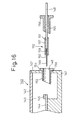
- a main container 140 is composed of a receptacle member 141 and a lid member 142 and is provided with a main chamber 143.
- An optical element 144 is fixed together with a connection-reinforcing block 145 on a bottom of the receptacle member 141.
- An aperture 146 is formed in a side wall 147 of the receptacle member 141.
- An end portion of an optical fiber 148 comprises a naked core fiber section 149, a surface-metallized core fiber section 150 and a coating fiber-coated section 151.
- a sleeve 152 is composed of an outer tube 153 having an annular projection 154, an intermediate tube 155 having an annular projection 156, and an inner tube 157.
- the outer tube 153 is inserted into the aperture 146 and gas-hermetically bonded at the annular projection 154 to the side wall 147 of the main container 140 with an adhesive or solder 158.
- the end portion of the optical fiber 148 is passed through the intermediate tube 155 and then through the inner tube 157, and a moiety of the coating layer-coated section 151 and a moiety of the surface-metallized core fiber section 150 continued to the moiety of the section 151 is located in the hollow space of the inner tube 157.
- An adhesive material 159 is applied into the hollow spaces of the inner tube 157 to fix the moiety of the surface-metallized core fiber section 150 to the inner tube 157.
- the inside diameter of the outer tube 153 is established so that the end portion of the optical fiber 148 can be easily introduced into the main chamber 143, the optical axis of the optical fiber can be aligned with the optical axis of the optical element 144, and a terminal face of the optical fiber can be connected to a terminal face of the optical element.
- the inside diameter of the outer tube 153 is preferably larger than the outside diameter of the inner tube 157.
- the naked core fiber section 149 of the optical fiber 148 is introduced into the main chamber 143 through the outside tube 153, the terminal moiety of the naked core fiber section 149 is position-adjusted so that the optical axis of the terminal moiety of the naked core fiber section 149 can be aligned with the optical axis of the terminal portion of the optical element 144, and a terminal face of the naked core fiber section 149 can be connected to a terminal face of the optical element 144.
- the connection is fixed and reinforced by the reinforcing block 145.
- the inner tube 157 is located in the hollow space of the outer tube 153.
- the intermediate tube 155 is inserted and fixed between the outer tube 153 and the inner tube 157.
- the end opening of the outside tube 153 located in the main chamber 143 is sealed with solder. Also, portions of the outer, intermediate and inner tubes located outside of the main container 140 are completely sealed with an adhesive.
- connection of the optical fiber 148 and the optical element 144 is reinforced by a reinforcing device, for example, glass capillary 160 together with the reinforcing block 145.
- a reinforcing device for example, glass capillary 160 together with the reinforcing block 145.
- the open end of the outer tube 153 located in the main chamber 143 is sealed by a solder layer 161 through which a moiety of the surface-metallized core fiber section 150 extends and a connection of the inner tube 157 and the intermediate tube 155 is sealed by an adhesive layer 162.
- the distance L a between the connection between the optical element and the optical fiber and the solder layer 161 can be relatively short, for example, 2 to 10 mm. Accordingly, this short distance L a advantageously makes the alignment of the optical axis of the optical element with that of the optical fiber easy.
- the intermediate tube of the sleeve is composed of an outside intermediate tube 163 and an inside intermediate tube 164.
- the outside intermediate tube 163 has a hollow space including a portion 165 thereof suitable for receiving the inside intermediate tube 164 and another portion 166 having a smaller diameter than that of the above-mentioned portion 165 and opening to the main chamber 143.
- the outside intermediate tube 163 is advantageous in that during the connecting operation of the optical fiber to the optical element, the inside tube 157 including the optical fiber 148 is restricted to excessively move toward the optical element.
- the outside intermediate tube 163 and the outside tube 154 are gas-hermetically fixed to each other with an adhesive.
- the gap between the outside intermediate tube 163 and the inner tube 157 is sealed by inserting the inside intermediate tube 164 thereinto and gas-hermetically fixing them with an adhesive. Therefore, in this type of composite sleeve, the adhesive layer 162 shown in Fig. 17 can be omitted.
Landscapes
- Physics & Mathematics (AREA)
- General Physics & Mathematics (AREA)
- Optics & Photonics (AREA)
- Optical Couplings Of Light Guides (AREA)
- Light Guides In General And Applications Therefor (AREA)
Description
- The present invention relates to a package structure for housing an optical element and gas-hermetically sealing optical fibers connected to the optical element, and a composite structure of an optical element and optical fibers housed and gas-hermetically sealed in the above-mentioned package structure.
- The package structure and the optical element-optical fiber composite structure of the present invention are useful for optical devices comprising an optical waveguide electro-optical element.
- In a conventional optical element-optical fiber composite structure in which an optical element is housed and gas-hermetically sealed in a package, a pair of optical fibers are connected to the optical element and extended to the outside of the package through sleeves attached to the package, and the sleeves are gas-hermetically sealed. Usually, each optical fiber comprises a naked core fiber, and coating layers comprising a primary coat layer formed on the naked core fiber and a secondary coat layer formed on the primary coat layer. When the optical fiber is connected to the optical element, at an end portion of the optical fiber, the coating layer is removed so as to expose the naked core fiber to the outside, and a portion of the naked core fiber adjacent to a portion of the optical fiber coated with the coating layer or the primary coat layer is surface-metallized with a metal, for example, nickel and gold. A terminal face of the naked fiber portion is connected to a terminal face of the optical element through an adhesive, and the surface-metallized fiber portion is bonded to the sleeve with a moisture-nonpermeable bonding material, for example, solder. Namely, a gap between the peripheral surface of the surface-metallized fiber portion of the optical fiber located in the sleeve and an inside peripheral surface of the sleeve is sealed by the solder.
- Usually, the soldered surface-metallized fiber portion of the optical fiber exhibits a relatively low tensile strength of 0.5 to 1.5 kgf. An ideal tensile strength of the core fiber is about 6 kgf. Reasons for the reduction in the tensile strength of the soldered core fiber portion are assumed that microcracks are unavoidably formed on the naked core fiber portion while the coating layer is removed, a surface metallization is applied to the naked core fiber portion surface and soldering is applied to the surface-metallized core fiber portion.
- Therefore, it is practically difficult to enhance the tensile strength of the soldered portion of the surface-metallized core fiber portion. However, this tensile strength, namely a seal-fixing strength of the optical fiber to the package, is unsatisfactory.
- In a prior art, an attempt was made in which a portion of the optical fiber having the coating layer is inserted into the sleeve and the coating layer is bonded to the inside peripheral surface of the sleeve, to enhance the seal-fixing strength of the optical fiber to the package.
- Nevertheless, this attempt is disadvantageous in that generally, the coating layer and the core fiber are significantly different in expansion coefficient from each other, namely the core fiber has an expansion coefficient of one tenth (1/10) or less that of the coating layer, the coating layer retains a stress generated during the formation thereof, and therefore, when a heating and cooling are cyclically applied to the optical fiber, the coating layer is expanded and shrunk to an extent larger than that of the core fiber. If the interfacial bonding strength between the coating layer and the core fiber is low, it appears that the core fibers are pushed out from the coating layer when the coating layer shrinks and are pulled into the coating layer when the coating layer expands. The pushing and pulling distance of the core fiber due to the above-mentioned phenomenon is variable depending on the type and the material of the coating layer. When the secondary coat layer is made of a polyamide resin, the pushing and pulling length of the core fiber sometimes reaches more than several hundred µm within temperature range of -20 and 70°C. Also it is practically impossible to eliminate this phenomenon.
- In the above-mentioned type of sealing manner of the optical fiber to the sleeve, the optical fiber is fixed at two portions thereof spaced from each other, namely at the soldered portion of the surface-metallized fiber portion and the adhesive-bonded portion of the coating layer-coated portion. Where the core fiber pushed out from the coating layer, a non-fixed portion of the core fiber between the two fixing points is bent in the sleeve, and sometimes is broken by a compression buckling thereof due. to a buckling stress (localized tensile stress) generated therein.
- In practical use, the surface of the core fiber located in the sleeve is sometimes gradually corroded, and thus the buckling stress generated in the core fiber causes the corroded core fiber to be broken.
- Accordingly, there is a strong demand for preventing the generation of the buckling stress in the core fiber.
- To prevent the breakage of the core fiber due to the buckling stress, it has been attempted to make the distance between the fixing points of the optical fiber large enough to absorb and relax the deformation of the core fiber. However, this attempt was not successful because the large distance between the fixing points causes the resultant package structure for the optical element and the optical fibers to have too large a size.
- Preferred embodiments of the present invention enable one to provide a package structure for housing an optical element and gas-hermetically sealing optical fibers connected to the optical element, capable of preventing breakage of the optical fibers by a buckling stress generated due to change in environmental temperature, and a composite structure of an optical element and optical fibers housed and gas-hermetically sealed in the package structure.
- GB-A-2148535 discloses an optical coupler for use in connecting an optical waveguide to a transducer. The coupler has a main container with a side wall. A guide sleeve for the waveguide extends through the side wall and through a protective sleeve which is mounted to the main container.
- GB-A-2264789 discloses a package structure for housing an optical element and gas-hermetically sealing optical fibers connected to the optical element, which comprises:
- a main container provided with a main chamber for housing an optical element therein;
- a pair of side containers attached to the main container and provided with a pair of side chambers formed therein and separated from the main chamber through a pair of side walls, and having a pair of apertures through which the side chambers are connected to the outside of the side chambers; and
- a pair of sleeves extending from or across the side walls and provided with a pair of hollow spaces through which the main chamber is connected to the side chambers;
- said apertures and side chambers of the side containers and said hollow spaces of the sleeves being suitable for introducing a pair of optical fibers into the main chamber of the main container therethrough, to connect the optical fibers to the optical element. According to the present invention as set forth in claim 1, the side chambers of the side containers are connected to each other through a connecting passage which is arranged outside of the main container, said connecting passage allowing each of said optical fibers to be introduced into a respective one of the side chambers from the other side chamber via said connecting passage.
-
- In the present invention, the package structure is used to form an optical element-optical fiber composite structure.
- In this composite structure of an optical element and optical fibers housed and gas-hermetically sealed in the package structure, an optical element is housed in the main chamber; end portions of optical fibers which comprise secondary coat sections thereof composed of core fibers and primary and secondary coatings, primary coat sections thereof continued from the secondary coat sections and composed of core fibers and primary coatings, surface-metallized core fiber sections thereof continued from the primary coat sections and composed of surface-metallized core fibers, and naked core fiber sections thereof continued from the surface-metallized core fiber sections and composed of naked core fibers, are introduced into the main chamber through the apertures and side chambers of the side containers and the hollow spaces of the sleeves; the terminal faces of the naked core fiber sections are connected to the terminal faces of the optical element; moieties of the surface-metallized core fiber sections located in the hollow spaces of the sleeves are fixed to the sleeves through moisture-non-permeable bonding material layers formed in gaps between the surface-metallized core fiber moieties and the inside peripheral surfaces of the sleeves; and moieties of the secondary coat sections located in the apertures of the side containers are fixed to the side containers.
-
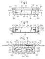
- Fig. 1 is an explanatory plane view of an embodiment of the package structure of the present invention from which a lid is omitted;
- Fig. 2 is an explanatory cross-sectional front view of the package structure of Fig. 1 along a line X-X;
- Fig. 3 is an explanatory plane view of an embodiment of the optical element-optical fiber composite structure containing the package structure of Figs. 1 and 2, from which a lid is omitted;
- Fig. 4(A) is an explanatory plane view of an embodiment of the main container usable for the present invention, from which a lid is omitted;
- Fig. 4(B) is an explanatory front view of the main container of Fig. 4(A);
- Fig. 4(C) is an explanatory side view of the main container of Figs. 4(A) and 4(B);
- Fig. 5(A) is an explanatory plane view of an embodiment of the side containers usable for the main container of Fig. 4 of the present invention, from which lids are omitted;
- Fig. 5(B) is an explanatory front view of the side containers of Fig. 5(A);
- Fig. 5(C) is an explanatory side view of the side containers of Figs. 5(A) and 5(B);
- Fig. 6(A) is an explanatory plane view of another embodiment of the optical element-optical fiber composite structure of the present invention containing the container structure of Figs. 4(A) to 5(C), from which lids are omitted;
- Fig. 6(B) is an explanatory back view of the optical element-optical fiber composite structure of Fig. 6(A);
- Fig. 7 shows a relationship between a center line of a sleeve and an axial line of an optical element of another embodiment of the optical element-optical fiber composite structure of the present invention;
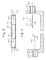
- Fig. 8 shows an explanatory cross-sectional front view of an embodiment of the optical element-optical fiber connection in the main container of the present invention in which the optical fibers are connected at an inclined angle to an axial line of the optical element;
- Fig. 9 is an explanatory cross-sectional front view of portions of the main container of the present invention in which the center lines of sleeves attached to the main container inclines to an axial line of the optical element;
- Fig. 10 is an explanatory cross-sectional front view of a conventional connection between an optical fiber and an optical element;
- Fig. 11 is an explanatory cross-sectional front view of an embodiment of the improved connection of the present invention between an optical fiber and an optical element;
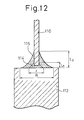
- Fig. 12 is an explanatory cross-sectional front view of another embodiment of the improved connection between an optical fiber and an optical element;
- Fig. 13 (A) is an explanatory plane view of another embodiment of a right half portion of a main container usable for the present invention, from which a lid member is omitted;
- Fig. 13(B) is an explanatory cross-sectional front view of the main container of Fig. 13(A);
- Fig. 14(A) is an explanatory cross-sectional view of a portion of a main container usable for the present invention;
- Fig. 14(B) is an explanatory cross-sectional view of a core fiber section of an optical fiber fixed to the main container of Fig. 14(A);
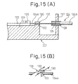
- Fig. 15(A) is an explanatory cross-sectional view of a portion of a main container usable for the present invention;
- Fig. 15(B) is an explanatory over view of a portion of the main container of Fig. 15(A);
- Fig. 16 is an explanatory cross-sectional front view of another embodiment of the main chamber and a composite sleeve usable for the package structure of the present invention;
- Fig. 17 is an explanatory cross-sectional front view of another embodiment of the main chamber and another composite sleeve usable for the package structure of the present invention; and
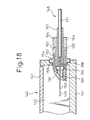
- Fig. 18 is an explanatory cross-sectional front view of another embodiment of the main container and another composite sleeve usable for the container structure of the present invention.
-
- In an embodiment of the package structure of the present invention, the side chambers of the side containers are connected to each other through a connecting passage arranged outside of the main container. The connecting passage allows a pair of optical fibers to be introduced from one of the side chambers to the other one therethrough.
- The above-mentioned type of package structure of the present invention has the following advantages.
- (1) The optical fibers can be fixed in coating layer-coated sections thereof to the side containers, and thus core fiber sections of the optical fibers located in the main chamber are prevented from harmful stress and the sealing conditions of the sleeves attached to the main container can be stably maintained at a good level over a long period of time.
- (2) Since sections of the optical fibers between the apertures of the side containers and the sleeves of the main container can be made long and curved, the core fiber sections of the optical fibers located in the main chamber can be prevented from harmful stress and the sealing conditions of the sleeves of the main container can be maintained at a good level with a high degree of stability over a long period of time.
-
- Referring to Figs. 1 and 2, a
package structure 63 of the present invention comprises amain container 64 andside containers main container 64 has amain chamber 66 formed therein and theside containers side chambers package structure 63 is further provided with a connectingpassage 68 formed between aside wall 69 of themain container 64 and a connectingside wall 70 through which theside containers passage 68 allows theside chambers - The
side chambers main chamber 66 throughside walls side containers apertures side walls side walls main container 64 hassleeves side walls apertures side containers sleeves - Referring to Fig. 3,
optical fibers package structure 63. End portions of coating layer-coatedsections optical fibers passage 68 through the optical fiber-fixing means 75a and 75b and theside chambers sections passage 68 and theside chambers sleeves sleeves core fiber sections sleeves core fiber sections optical fibers main chamber 66 are optionally slightly curved and connected at terminal faces thereof to the terminal faces of theoptical element 21. The connections of the optical fiber terminal faces to the optical element terminal faces are protected byprotectors - Referring to Figs. 4(A), 4(B) and 4(C), an embodiment of the
main container 64 is in the form of a hexahedron and composed of areceptacle member 83 and a lid member (not shown) for gas-hermetically closing thereceptacle member 83. To a pair ofside walls receptacle member 83,sleeves front wall 85 of themain container 64, agroove 86 is formed as a connecting passage for the optical fibers. - Referring to Figs. 5(A), 5(B) and 5(C),
side containers bottom plate 87 on which themain container 64 of Figs. 4(A) to (C) is also placed,side walls side walls side containers grooves - Referring to Figs. 6(A) and 6(B), the package structure of the present invention is formed from the main container as shown in Figs. 4(A) to (C) and the side containers as shown in Figs. 5(A) to (C). An
optical fiber 76a is introduced into themain chamber 66 through theaperture 89a, theside chamber 67a, the connectinggroove 86, theside chamber 67b and thesleeve 74b. The otheroptical fiber 76b is introduced into themain chamber 66 through theaperture 89b, theside chamber 67b, the connectinggroove 86, theside chamber 67a and thesleeve 74a. - In an embodiment of the package structure of the present invention, with respect to each sleeve attached to the main container, the center line of the hollow space of the sleeve intersects an axial line of a corresponding terminal of the optical element fixed in the main container. The intersecting angle between the sleeve hollow space center line and the optical element terminal axial line is in the range of from 2 to 5 degrees.
- Usually, where an optical fiber having a coating layer covering a core fiber has a diameter of 0.9 mm, the sleeve for the optical fiber has an inside diameter of about 1 mm. The gap between the inside peripheral surface of the sleeve and the optical fiber inserted into the sleeve is sealed by solder. When a core fiber section having a diameter of 0.125 mm of the optical fiber is located in the sleeve and fixed to the sleeve by the solder, the gap between the inside surface of the sleeve and the core fiber section of the optical fiber is preferably made smaller. For this purpose, sometimes, the inside diameter of an end of the sleeve opening to the main chamber is reduced to about 0.6 mm. Usually, the center line of the sleeve is parallel to the axial line of the main container.
- For example, in a waveguide type electro-optical element which has potential use as an external modulator for an optical communication system, the connection of the terminal faces of the optical element to the terminal faces of the optical fibers is carried out by using an adhesive having a low refractive index to reduce a reflection of light at the connection. Also in the connection, an inclined incidence system is usually employed.
- Where the core fiber section of the optical fiber is introduced into the main chamber through the sleeve having a very small inside diameter, and is connected to the optical element, the core fiber section must be bent so as to impart an inclined incidence angle, for example, 5 to 7 degrees, to the axial line of the terminal of the optical element. This bending sometimes causes the core fiber section to be brought into contact with the edge of the sleeve and to be broken or scratched. Accordingly, this connecting operation is not always easy.
- The above-mentioned feature of the package structure effectively allows the core fiber sections of the optical fibers to be connected to the optical element at a desired angle, without damaging the core fiber sections of the optical fibers.
- Referring to Fig. 7, a
main container 90 has asleeve 91, and anoptical element 97 is fixed on astand 92 in amain chamber 93. A terminal face 94 of theoptical element 97 is inclined at an angle R1 (not shown in Fig. 7), for example , 5 degrees, from a plane 95 crossing at right angles to theaxial line 96 of theoptical element 97. Also, a terminal face of aglass capillary 98 through which a terminal of an optical fiber is connected to the terminal face 94 of theoptical element 97, is inclined at an angle R2, for example, 7 degrees, from a plane crossing at right angles to the center line of the optical fiber inserted into the capillary 98. In this case, the optical fiber can be connected to the optical element at an angle of R2, for example, 7 degrees to the terminal face of the optical element, and at an angle of R3 = R2 - R1, for example, 7 - 5 = 2 degrees, to the axial line of the optical element. - A
center line 99 of thesleeve 91 intersects theaxial line 96 of theoptical element 97 at an angle R3, preferably of 2 to 5 degrees. - Referring to Fig. 8, in a
main container 100 having amain chamber 101, anoptical element 102 is fixed. A pair ofsleeves 103a and 103b are attached to a pair ofside walls optical fibers main chamber 101 through thesleeves 103a and 103b and connected to terminal faces of theoptical element 102. The center lines of thesleeves 103a and 103b are inclined to the axial line of the optical element at a small angle R3 as shown in Fig. 7. - In Fig. 9, the sleeve attached to the
side wall 104a has a center line 106a inclined at an angle R3a to ahorizontal line 107a parallel to an axial line of an optical element (not shown). Also, thesleeve 103b attached to theside wall 104b has acenter line 106b inclined at an angle R3b to ahorizontal line 107b parallel to the axial line of the optical element (not shown). The angles R3a and R3b are preferably 2 to 5 degrees. - In the above-mentioned connection manner, the core fiber sections of the optical fibers can be connected to the terminals of the optical element at a desired incidence angle without breaking or damaging the core fiber sections.
- When a terminal face of a naked core fiber section of an optical fiber is connected to a terminal face of an optical element, usually, a connection-reinforcing device is used. The connection-reinforcing device is a glass block having a V-shaped groove for receiving the naked core fiber section, or a glass capillary having a hollow space for receiving the naked core fiber section.
- Referring to Fig. 10 showing a conventional connection of an optical element to an optical fiber through a glass capillary, a
glass capillary 108 has a hollow space, and a nakedcore fiber section 110 of an optical fiber is inserted into thehollow space 109. The inserted nakedcore fiber section 110 is bonded to theglass capillary 108 through an adhesive 111. Theglass capillary 108 with the nakedcore fiber section 110 is bonded to the terminal face of anoptical element 112 with abinder 113. In another manner, the nakedcore fiber section 110 of the optical fiber passes through the capillary 108, the terminal face of the nakedcore fiber section 110 is connected to the terminal face of theoptical element 112 by an adhesive, the terminal face of the capillary 108 is bonded to the terminal face of theoptical element 112 by the adhesive, and then the adhesive is injected into thehollow space 109 of theglass capillary 108 so as to fix the nakedcore fiber section 110 to the inside peripheral surface of theglass capillary 108. - When the connection-reinforcing block having a V-shaped groove is used, a terminal face of the block is bonded to a terminal face of the optical element by an adhesive, the naked core fiber section of the optical fiber is placed in the groove, the terminal face of the naked core fiber section is bonded to the terminal face of the optical element, and the naked core fiber section in the groove is bonded to the block by an adhesive.
- In the above-mentioned conventional manners of connecting the optical element to the optical fiber, it is difficult to arrange the terminal face of the capillary on the same plane as that of the terminal face of the optical fiber. In this case, usually, the capillary terminal face is located farther from the terminal face of the optical element than the terminal face of the optical fiber. Namely, as shown in Fig. 10 the distance D between the terminal face of the optical element and the terminal face of the capillary is larger than the distance d between the terminal face of the optical element and the terminal face of the optical fiber. Therefore, the capillary cannot fully protect and reinforce the connection between the optical fiber and the optical element.
- Also, it is difficult to arrange the terminal face of the capillary in parallel to the terminal face of the optical fiber and thus the optical fiber inserted into the capillary is inclined to the center line of the hollow space of the capillary. In this case, the capillary cannot fully protect the optical fiber inserted therein, and the connection between the optical element and the optical fiber becomes unstable.
- The above-mentioned disadvantages can be removed by the following connection procedures.
- Referring to Figs. 11 and 12, in an end of each optical fiber, a terminal face of a naked
core fiber section 110 of the optical fiber is connected to a terminal face of anoptical element 112 through afirst bonding layer 114 consisting of a resinous adhesive and having a refractive index of 1.4 to 1.6, and thefirst bonding layer 114 is covered by asecond bonding layer 115 consisting of a resinous adhesive and spreading between the peripheral surface of the end portion of the nakedcore fiber section 110 and the terminal face of theoptical element 112. - In the
first bonding layer 114, preferably the terminal face of the nakedcore fiber section 110 of the optical fiber is embedded in a top portion of thefirst bonding layer 114 and thus peripheral surface of the embedded portion of the nakedcore fiber section 110 is covered by thefirst bonding layer 114. Also, thefirst bonding layer 114 is in the form of a substantial circular cone symmetrical around the axial line of the nakedcore fiber section 110. - The circular cone-shaped
first bonding layer 114 preferably has a diameter r of the bottom face thereof of 130 to 200 µm. - Also, the distance between the terminal face of the
optical element 112 and the terminal face of the nakedcore fiber section 110 is preferably about 50 µm or less. Further, the end portion of the nakedcore fiber section 110 is preferably embedded at a depth of 5 to 50 µm in thefirst bonding layer 114 and the first bonding layer preferably has a height L1 of about 50 µm. - The first bonding layer is preferably formed from a resinous adhesive having a relatively low viscosity, for example, an ultraviolet ray irradiation-curable adhesive which is useful for forming a circular cone-shaped or bell-shaped bonding layer.
- The first bonding layer exhibits a relatively low bonding strength of 2 to 3 gf.
- In a cross-sectional profile of the first bonding layer, the edge line may be a straight line or a curved line projecting outward or inward (Figs. 11 and 12).
- Referring to Figs. 11 and 12, a resinous adhesive is coated on the
first bonding layer 114 to form asecond bonding layer 115. Preferably, thesecond bonding layer 115 is in the form of a circular cone or a bell symmetrical about the axial line of the nakedcore fiber section 110 of the optical fiber. Thesecond bonding layer 115 preferably has a diameter R of the bottom thereof of 500 to 1000 µm and a height L2 of 100 to 1000 µm. - Due to the formation of the second bonding layer on the first bonding layer, the bonding strength between the optical element and the optical fiber is enhanced to a high level of 100 to 1000 gf. In the cross-sectional profile of the second bonding layer, the edge line is in the form of a straight line or a curved line projecting outward (Fig. 11) or inward (Fig. 12).
- The first bonding layer is formed from a resinous adhesive having a refractive index of 1.4 to 1.6, to provide a good optical connection between the optical element and the optical fiber. The resinous adhesive for the first bonding layer may be selected from ultraviolet ray-curable epoxy resins and ultraviolet ray-curable acrylate resins for optical use.
- The second bonding layer is formed from the same resinous adhesive as that for the first bonding layer or another resinous adhesive softer than that for the first bonding layer. For example, the soft resinous adhesive for the second bonding layer is selected from silicone resins and polyurethane resins which are capable of preventing an undesirable concentration of stress in the connection between the optical element and the optical fiber.
- The connection between a terminal face of an optical element and a terminal face of a naked core fiber section of an optical fiber is reinforced by using a block for supporting the naked core fiber section, or a capillary. The naked core fiber section is inserted into a hollow space of the capillary, and the terminal face of the capillary is connected together with the terminal face of the naked core fiber section to the terminal face of the optical element. This connection of the capillary is optionally further reinforced by using a block bonded to both the capillary and the optical element. When the block is used, the block must be bonded to a bottom surface of the main container, and the naked core fiber section is also connected to the optical element. The bonding of the block sometimes reduces the reliability of the resultant optical device.
- Also, if the capillary is used, the arrangement of the capillary which is rigid in the connection between the optical element and the optical fiber sometimes causes a slight movement of the optical fiber due to vibration, impact or cyclical heating applied to the connection.
- The above-mentioned disadvantages can be removed in the following manner.
- In the main container of the present invention, a first bottom portion on which the optical element is fixed and a pair of second bottom portions located between the optical element and the sleeves are provided. The upper faces of the second bottom portions are higher than the upper face of the first bottom portion and lower than the lower faces of the optical fiber sections located above the second bottom portions. Also, moieties of the optical fiber sections are fixed to the upper faces of the second bottom portions by fixing means.
- Preferably, the moieties of the optical fiber sections located above the second bottom portions are moieties of surface-metallized core fiber sections and are fixed to the upper faces of the second bottom portions with solder layers surrounding the moieties of surface-metallized core fiber sections. Alternatively, the moieties of the optical fiber sections located above the second bottom portions are moieties of the naked core fiber sections and are fixed to the upper faces of the second bottom portions with a resinous adhesive layers surrounding the naked core fiber moieties. Preferably, in each second bottom portion, the distance between a connecting terminal face of the optical element and an end of the second bottom portion closest to the optical element is 5 mm or less, measured in parallel to the upper face of the first bottom portion.
- Figs. 13(A) and 13(B) show a right half portion of a main chamber of the present invention in which an optical fiber is connected to an optical element.
- In Figs. 13(A) and 13(B), a
main container 116 is formed from areceptacle member 117 and alid member 118 and has amain chamber 119. A bottom 120 of thereceptacle member 117 has afirst bottom portion 121, on which anoptical element 122 is fixed, and asecond bottom portion 123 facing a passage of anoptical fiber 124 connected to theoptical element 122. - The
second bottom portion 123 has an upper face thereof higher than that of an upper face of thefirst bottom portion 121. The upper face of thesecond bottom portion 123 is spaced from a lower face of the passage of theoptical fiber 124. Namely, the upper face of thesecond bottom portion 123 is lower than and spaced from the lower face of the optical fiber passage. Asection 124a of theoptical fiber 124 located in themain chamber 119 consists of a naked core fiber. A terminal face of the nakedcore fiber section 124a is connected to a terminal face of theoptical element 122, and the connection is reinforced by a connectingadhesive layer 125 and a reinforcingblock 126. Usually, the surface of thecore fiber section 124a is metallized with gold, nickel or a bi-layer of gold and nickel. - A
side wall 127 has an aperture and asleeve 128 is inserted into the aperture. An end portion of a coatinglayer coating section 124b of theoptical fiber 124 is inserted into a hollow space of thesleeve 128. Thissection 124b continues to thecore fiber section 124a. A moiety of thecore fiber section 124a located in the hollow space of thesleeve 128 is fixed to the inside peripheral surface of thesleeve 128 bysolder 129. Accordingly, the hollow space of thesleeve 128 is completely sealed by thesolder 129. - A moiety of the
core fiber section 124a located immediately above thesecond bottom portion 123 is fixed to the upper face of thesecond bottom portion 123 by a fixing means 130 surrounding the moiety of thecore fiber section 124a. The fixing means 130 may comprise solder or a resinous adhesive. - A portion of the bottom 117 between the
side wall 127 and the second bottom portion is not limited to a specific form and dimensions. In Fig. 13(B), this bottom portion is formed lower than thefirst bottom portion 121. However, this bottom portion may have the same level as that of thefirst bottom portion 121. - Referring to Figs. 14(A) and 14(B), a gap S between the upper face of the
second bottom portion 123 and the lower face of thecore fiber section 124 of the optical fiber, a height H of acenter line 131 of thecore fiber section 124a from the upper face of thefirst bottom portion 121, a height h of the second bottom portion upper face from the first bottom portion upper face, and a diameter R of thecore fiber section 124a have the following relationship: - To avoid that the core fiber section being brought into contact with the second bottom portion and damaged, S is preferably adjusted to a level of 100 µm or more. Also, H is preferably almost equal to the thickness of the optical element, and R is usually 125 µm. When the values of S, H and R are established, it is easy to establish the value of h.
- In Fig. 14(A), a distance L between the terminal face of the
optical element 122 and an end of thesecond bottom portion 123 closest to theoptical element 122 is established so that the connecting operation of the terminal face of theoptical element 122 to the terminal face of thecore fiber section 124a of the optical fiber can be easily carried out, theoptical element 122 can be easily fixed to the first bottom portion, and the soldering operation of the core fiber section to the second bottom portion can be carried out while preventing an undesirable influence on the optical element-optical fiber connection. Preferably, the distance L is 5 mm or less, more preferably 2 to 5 mm. Usually, the main container is made from a metal material, for example, a brass, stainless steel or a Kovar steel, and the core fiber is made from quartz. The difference in thermal expansion between the metal materials and quartz is in the order of 10-5/°C. - If the optical element structure is used in an environment in which a change in temperature is about 100°C, the distance L is preferably 5 mm or less to restrict the change in length of the core fiber section to a level of several µm.
- Referring to Figs. 15(A) and 15(B), the
second bottom portion 123 is formed by a bottom face of agroove 131 of aprojection 132. Thecore fiber section 124a of the optical fiber passes across thegroove 131 and is fixed to thegroove 131 by fixingmeans 130. In this case, the amount of the fixing means 130 applied to thecore fiber section 124a of the optical fiber can be easily controlled by thegroove 131 having a known depth, width and length. - In an embodiment of the package structure of the present invention, each sleeve comprises an outer tube extending through and fixed to the side wall of the main container, an intermediate tube inserted into the outer tube and an inner tube inserted into the intermediate tube and having a hollow space allowing the optical fiber to be inserted thereinto and connected to the main chamber of the main container. This type of sleeve is contributory to making the total length of the package structure shorter. Also, the sleeve effectively shortens the length of a portion of the optical fiber located in the main chamber of the package structure. In Fig. 16, a
main container 140 is composed of areceptacle member 141 and alid member 142 and is provided with amain chamber 143. Anoptical element 144 is fixed together with a connection-reinforcingblock 145 on a bottom of thereceptacle member 141. - An
aperture 146 is formed in aside wall 147 of thereceptacle member 141. - An end portion of an
optical fiber 148 comprises a nakedcore fiber section 149, a surface-metallizedcore fiber section 150 and a coating fiber-coatedsection 151. - A
sleeve 152 is composed of anouter tube 153 having anannular projection 154, anintermediate tube 155 having anannular projection 156, and aninner tube 157. - The
outer tube 153 is inserted into theaperture 146 and gas-hermetically bonded at theannular projection 154 to theside wall 147 of themain container 140 with an adhesive orsolder 158. - The end portion of the
optical fiber 148 is passed through theintermediate tube 155 and then through theinner tube 157, and a moiety of the coating layer-coatedsection 151 and a moiety of the surface-metallizedcore fiber section 150 continued to the moiety of thesection 151 is located in the hollow space of theinner tube 157. Anadhesive material 159 is applied into the hollow spaces of theinner tube 157 to fix the moiety of the surface-metallizedcore fiber section 150 to theinner tube 157. - The inside diameter of the
outer tube 153 is established so that the end portion of theoptical fiber 148 can be easily introduced into themain chamber 143, the optical axis of the optical fiber can be aligned with the optical axis of theoptical element 144, and a terminal face of the optical fiber can be connected to a terminal face of the optical element. For this purpose, the inside diameter of theouter tube 153 is preferably larger than the outside diameter of theinner tube 157. - The naked
core fiber section 149 of theoptical fiber 148 is introduced into themain chamber 143 through theoutside tube 153, the terminal moiety of the nakedcore fiber section 149 is position-adjusted so that the optical axis of the terminal moiety of the nakedcore fiber section 149 can be aligned with the optical axis of the terminal portion of theoptical element 144, and a terminal face of the nakedcore fiber section 149 can be connected to a terminal face of theoptical element 144. The connection is fixed and reinforced by the reinforcingblock 145. Theinner tube 157 is located in the hollow space of theouter tube 153. Theintermediate tube 155 is inserted and fixed between theouter tube 153 and theinner tube 157. The end opening of theoutside tube 153 located in themain chamber 143 is sealed with solder. Also, portions of the outer, intermediate and inner tubes located outside of themain container 140 are completely sealed with an adhesive. - In Fig. 17, the connection of the
optical fiber 148 and theoptical element 144 is reinforced by a reinforcing device, for example,glass capillary 160 together with the reinforcingblock 145. The open end of theouter tube 153 located in themain chamber 143 is sealed by asolder layer 161 through which a moiety of the surface-metallizedcore fiber section 150 extends and a connection of theinner tube 157 and theintermediate tube 155 is sealed by anadhesive layer 162. - In the assembly as shown in Fig. 17, the distance La between the connection between the optical element and the optical fiber and the
solder layer 161 can be relatively short, for example, 2 to 10 mm. Accordingly, this short distance La advantageously makes the alignment of the optical axis of the optical element with that of the optical fiber easy. - In Fig. 18, the intermediate tube of the sleeve is composed of an outside
intermediate tube 163 and an insideintermediate tube 164. The outsideintermediate tube 163 has a hollow space including aportion 165 thereof suitable for receiving the insideintermediate tube 164 and anotherportion 166 having a smaller diameter than that of the above-mentionedportion 165 and opening to themain chamber 143. The outsideintermediate tube 163 is advantageous in that during the connecting operation of the optical fiber to the optical element, theinside tube 157 including theoptical fiber 148 is restricted to excessively move toward the optical element. The outsideintermediate tube 163 and theoutside tube 154 are gas-hermetically fixed to each other with an adhesive. The gap between the outsideintermediate tube 163 and theinner tube 157 is sealed by inserting the insideintermediate tube 164 thereinto and gas-hermetically fixing them with an adhesive. Therefore, in this type of composite sleeve, theadhesive layer 162 shown in Fig. 17 can be omitted.
Claims (21)
- A package structure (63) for housing an optical element (21) and gas-hermetically sealing optical fibers (76a,76b) connected to the optical element (21), comprising:
a main container (64) provided with a main chamber (66) for housing an optical element (21) therein:a pair of side containers (65a,65b) attached to the main container and provided with a pair of side chambers (67a,67b) formed therein and separated from the main chamber (66) through a pair of side walls (71a,71b), and having a pair of apertures (72a,72b) through which the side chambers are connected to the outside of the side chambers; anda pair of sleeves (74a,74b) extending from or across the side walls and provided with a pair of hollow spaces through which the main chamber (66) is connected to the side chambers (67a,67b);said apertures and side chambers of the side containers and said hollow spaces of the sleeves being suitable for introducing a pair of optical fibers (76a,76b) into the main chamber of the main container therethrough, to connect the optical fibers to the optical element; characterized in that the side chambers (67a,67b) of the side containers (65a,65b) are connected to each other through a connecting passage (68) which is arranged outside of the main container (64), said connecting passage (68) allowing each of said optical fibers (76a,76b) to be introduced into a respective one of the side chambers (67a,67b) from the other side chamber via said connecting passage. - The package structure as claimed in claim 1, wherein the sleeves (103a,103b) extend from the side walls only in opposite directions with respect to the main container (100).
- The package structure as claimed in claim 1 or 2 wherein the side containers are in the form of cylinders surrounding the sleeves.
- The package structure as claimed in any preceding claim wherein the connecting passage (68) is formed in an enclosure (69) connected to the outside surface of the main container.
- The package structure as claimed in any of claims 1 to 3 wherein the connecting passage is in the form of at least one groove (86) formed on an outside surface portion (85) of the main container (64).
- An assembly of an optical element (21) housed in the package structure as claimed in any preceding claim wherein with respect to each sleeve, the center line (106a,b) of the hollow space of the sleeve intersects an axial line of a corresponding terminal of the optical element placed in the main chamber.
- The assembly as claimed in claim 6 wherein an intersecting angle between the sleeve hollow space center line and the optical element terminal axial line is in the range of from 2 to 5 degrees.
- The package structure or assembly as claimed in any preceding claim wherein the main container (116) has a first bottom portion (121) for fixing the optical element (122) thereon and a pair of second bottom portions (123) located between the first bottom portion and the sleeves (128) and facing the optical fiber passage, and the upper faces of the second bottom portions are higher than the upper face of the first bottom portion and lower than the lower face of the optical fiber passage.
- The package structure or assembly as claimed in claim 8 wherein the second bottom portions are in the form of grooves.
- The package structure or assembly as claimed in any preceding claim wherein each sleeve (152) comprises an outer tube (153) extending through and fixed to the side wall (147), an intermediate tube (155) inserted into the outer tube and an inner tube (157) inserted into the intermediate tube and having a hollow space allowing the optical fiber to be inserted thereinto.
- A composite structure of an optical element (21) and optical fibers (76a,b) housed and gas-hermetically sealed in the package structure as claimed in any of claims 1-5,8,9 and 10 wherein an optical element (21) is housed in the main chamber (66); end portions (77a,b) of optical fibers which comprise secondary coat sections thereof composed of core fibers and primary and secondary coatings, primary coat sections (78a,b) thereof continued from the secondary coat sections and composed of core fibers and primary coatings, surface-metallized core fiber sections (79a,b) thereof continued from the primary coat sections and composed of surface-metallized core fibers, and naked core fiber sections (81a,b) thereof continued from the surface-metallized core fiber sections and composed of naked core fibers, are introduced into the main chamber (66) through the apertures and side chambers of the side containers (65a,b), said connecting passage (68) and the hollow spaces of the sleeves (74 a,b); the terminal faces of the naked core fiber sections are connected to the terminal faces of the optical element; moieties of the surface-metallized core fiber sections located in the hollow spaces of the sleeves are fixed to the sleeves through moisture-nonpermeable bonding material layers (80a,b) formed in gaps between the surface-metallized core fiber moieties and the inside peripheral surfaces of the sleeves; and moieties of the secondary coat sections located in the apertures of the side containers are fixed to the side containers.
- The optical element-optical fiber composite structure as claimed in claim 11, wherein the sleeves extend from the side walls only in opposite directions to the main container, and the surface-metallized core fiber moieties are fixed to the sleeves through solder layers injected into the hollow spaces of the sleeves.
- The optical element-optical fiber composite structure as claimed in claim 11 or claim 12 wherein center lines of the sleeve hollow spaces intersect axial lines of the optical element, and the naked core fiber sections of the optical fibers are connected to the optical element at inclined angles from the axial lines of the optical element.
- The optical element-optical fiber composite structure as claimed in any of claims 11-13 wherein in an end of each optical element (112), a terminal face of the naked core fiber section (110) is connected to a terminal face of the optical element through a first bonding layer (114) consisting of a resinous adhesive and having a refractive index of 1.4 to 1.6, and the first bonding layer is covered by a second bonding layer (115) consisting of a resinous adhesive and spreading between the peripheral surface of the end portion of the naked core fiber section and the terminal face of the optical element.
- The optical element-optical fiber composite structure as claimed in claim 14, wherein the bonding material for the first bonding layer is the same as the bonding material for the second bonding layer.
- The optical element-optical fiber composite structure as claimed in claim 14, wherein the bonding material for the second bonding layer is softer than the bonding material for the first bonding layer.
- The optical element-optical fiber composite structure as claimed in any of claims 11-16 wherein the main container has a first bottom portion (121) on which the optical element is fixed and a pair of second bottom portions (123) located between the optical element and the sleeves (128), the upper faces of the second bottom portions are higher than the upper face of the first bottom portion and lower than the lower faces of the optical fiber sections located above the second bottom portions, and moieties of the optical fiber sections are fixed to the upper faces of the second bottom portions with fixing means.
- The optical element-optical fiber composite structure as claimed in claim 17, wherein the moieties of the optical fiber sections located above the second bottom portions are moieties of surface-metallized core fiber sections and are fixed to the upper faces of the second bottom portions with solder layers surrounding the moieties of the surface-metallized core fiber sections.
- The optical element-optical fiber composite structure as claimed in claim 17, wherein the moieties of the optical fiber sections located above the second bottom portions are moieties of the naked core fiber sections and are fixed to the upper faces of the second bottom portions with resinous adhesive layers surrounding the naked core fiber moieties.
- The optical element -optical fiber composite structure as claimed in claim 17,18 or 19 wherein in each second bottom portion, the distance between a connecting terminal face of the optical element and an end of the second bottom portion closest to the optical element is 5 mm or less, measured in parallel to the upper face of the first bottom portion.
- The optical element-optical fiber composite structure as claimed in any of claims 11 and 13-20 wherein each sleeve (152) comprises an outer tube (153) extending through and fixed to the side wall (147), an intermediate tube (155) inserted into the outer tube and an inner tube (157) inserted into the intermediate tube, and having a hollow space allowing the optical fiber to be inserted thereinto and connected to the main chamber of the main container, a moiety of the primary coat section and a moiety of the surface-metallized core fiber section continuing to the primary coat section moiety of the optical fiber are located in the inner tube and the surface-metallized core fiber section moiety is fixed to the inside peripheral surface of the inner tube through a resinous bonding material layer, and the open end of the sleeve, through which another moiety of the surface-metallized core fiber section extends into the main chamber, is sealed with a solder layer.
Applications Claiming Priority (21)
| Application Number | Priority Date | Filing Date | Title |
|---|---|---|---|
| JP33529193 | 1993-12-28 | ||
| JP336102/93 | 1993-12-28 | ||
| JP33610293 | 1993-12-28 | ||
| JP335291/93 | 1993-12-28 | ||
| JP33610293A JP3320537B2 (en) | 1993-12-28 | 1993-12-28 | Optical element storage sealed housing structure |
| JP33529193A JPH07199003A (en) | 1993-12-28 | 1993-12-28 | Housing structure for optical element |
| JP6075094A JPH07270643A (en) | 1994-03-30 | 1994-03-30 | Optical part, housing structure body for connecting optical fiber and connecting method therefor |
| JP6075094 | 1994-03-30 | ||
| JP60750/94 | 1994-03-30 | ||
| JP75798/94 | 1994-04-14 | ||
| JP6075798A JPH07281061A (en) | 1994-04-14 | 1994-04-14 | Sealing casing structure for optical element and optical fiber, and connecting-sealing complex thereof |
| JP7579894 | 1994-04-14 | ||
| JP7692894 | 1994-04-15 | ||
| JP7692894A JPH07287147A (en) | 1994-04-15 | 1994-04-15 | Method for connecting optical fiber and optical element |
| JP76928/94 | 1994-04-15 | ||
| JP9214794 | 1994-04-28 | ||
| JP6092147A JPH07294781A (en) | 1994-04-28 | 1994-04-28 | Casing structure for connecting and sealing optical element and optical fiber and composite body for connecting and sealing optical element and optical fiber including the same |
| JP92147/94 | 1994-04-28 | ||
| JP10395994A JPH07311321A (en) | 1994-05-18 | 1994-05-18 | Casing for housing optical element/optical fiber connector and structure for connecting optical element/ optical fiber |
| JP10395994 | 1994-05-18 | ||
| JP103959/94 | 1994-05-18 |
Publications (2)
| Publication Number | Publication Date |
|---|---|
| EP0662622A1 EP0662622A1 (en) | 1995-07-12 |
| EP0662622B1 true EP0662622B1 (en) | 2001-10-31 |
Family
ID=27565000
Family Applications (1)
| Application Number | Title | Priority Date | Filing Date |
|---|---|---|---|
| EP94309861A Expired - Lifetime EP0662622B1 (en) | 1993-12-28 | 1994-12-28 | Package structure for optical element and fibers and composite structure thereof |
Country Status (3)
| Country | Link |
|---|---|
| US (2) | US5613026A (en) |
| EP (1) | EP0662622B1 (en) |
| CA (1) | CA2138893C (en) |
Families Citing this family (30)
| Publication number | Priority date | Publication date | Assignee | Title |
|---|---|---|---|---|
| US5692086A (en) * | 1995-10-25 | 1997-11-25 | The Boeing Company | Optical fiber locking submount and hermetic feedthrough assembly |
| IT1283224B1 (en) * | 1996-03-11 | 1998-04-16 | Pirelli Cavi Spa | APPARATUS AND METHOD OF PROTECTION FOR OPTICAL FIBER DEVICES |
| JP4090512B2 (en) | 1997-04-08 | 2008-05-28 | 日本オプネクスト株式会社 | Optical module |
| GB2339300B (en) * | 1998-07-06 | 2002-10-16 | Bookham Technology Ltd | A hermetically sealed optic fibre package and method of assembly |
| JP4050402B2 (en) * | 1998-08-25 | 2008-02-20 | 日本オプネクスト株式会社 | Optoelectronic device and manufacturing method thereof |
| US6612752B2 (en) * | 1998-12-29 | 2003-09-02 | Corning Oti Spa | Sealed container for optical components and sealed feedthrough for optical fibers |
| US6292615B1 (en) | 1999-03-09 | 2001-09-18 | Uniphase Telecommunications Products, Inc. | Optical fiber feedthrough |
| JP2003515770A (en) * | 1999-11-30 | 2003-05-07 | コーニング・オー・テー・イー・エス・ペー・アー | Method for fixing optical fiber component of optical device, optical device obtained thereby, and polymer composition used in this optical device |
| JP4167378B2 (en) * | 2000-03-28 | 2008-10-15 | 京セラ株式会社 | Optical element module |
| FR2814550B1 (en) * | 2000-09-25 | 2002-12-06 | Schlumberger Services Petrol | OPTICAL CROSSING |
| GB2377276A (en) * | 2001-06-29 | 2003-01-08 | Bookham Technology Plc | Reinforcing the fibre when mounting an optical fibre cable to an optical device |
| WO2003023466A2 (en) * | 2001-09-07 | 2003-03-20 | Pirelli General Plc | Joining optical fibres |
| US6764228B2 (en) * | 2002-02-07 | 2004-07-20 | Veritech, Inc. | Outgas prevention in electrooptical packages |
| JP3682961B2 (en) * | 2002-02-07 | 2005-08-17 | フジノン株式会社 | Rod integrator holder |
| US7430081B2 (en) | 2002-02-28 | 2008-09-30 | Emcore Corporation | Sub-micron adjustable mount for supporting a component and method |
| US7126078B2 (en) | 2002-02-28 | 2006-10-24 | Emcore Corporation | Sub-micron adjustable mount for supporting a component and method |
| EP1347323A1 (en) * | 2002-03-19 | 2003-09-24 | Corning Incorporated | Photonic package based on multi-functional lid |
| JP3960935B2 (en) * | 2002-08-30 | 2007-08-15 | 住友大阪セメント株式会社 | Fixing method and fixing pipe for optical fiber in optical element module |
| US20040047571A1 (en) * | 2002-09-06 | 2004-03-11 | Boord Warren Timothy | Hermetically sealed ferrule |
| CN1313852C (en) * | 2003-09-27 | 2007-05-02 | 波若威科技股份有限公司 | Packaging method and structure of fiber optic devices |
| JP2006047956A (en) * | 2004-06-29 | 2006-02-16 | Anritsu Corp | Waveguide type optical device |
| US7309175B1 (en) * | 2006-07-28 | 2007-12-18 | Em4, Inc. | Reducing heating from non-coupled light in power transmitting optical fibers |
| WO2009025662A1 (en) * | 2007-08-17 | 2009-02-26 | Em4, Inc. | Reducing heating from non-coupled light in power transmitting optical fibers |
| US8611712B2 (en) * | 2008-03-31 | 2013-12-17 | Tomoegawa Co., Ltd. | Rubber member, adhesive connecting member, and optical connection structure |
| US8215848B1 (en) * | 2009-05-12 | 2012-07-10 | The Boeing Company | Methods and apparatus for making connections between optical fibers and optical components |
| JP5226856B1 (en) * | 2011-12-26 | 2013-07-03 | 株式会社フジクラ | Laser module and manufacturing method thereof |
| US9500808B2 (en) * | 2012-05-09 | 2016-11-22 | The Boeing Company | Ruggedized photonic crystal sensor packaging |
| JP5905563B1 (en) * | 2014-12-01 | 2016-04-20 | 株式会社フジクラ | Manufacturing method of semiconductor laser module |
| CN110073260B (en) * | 2016-12-16 | 2021-02-19 | 住友电气工业株式会社 | Optical connection parts |
| KR102316505B1 (en) | 2020-05-28 | 2021-10-22 | 한국전력기술 주식회사 | Triple sealing device for electronics housing of smart instrumentation |
Family Cites Families (15)
| Publication number | Priority date | Publication date | Assignee | Title |
|---|---|---|---|---|
| JPS56135801A (en) * | 1980-03-26 | 1981-10-23 | Nec Corp | Sealing method for glass fiber |
| JPS6011321B2 (en) * | 1981-01-20 | 1985-03-25 | ケイディディ株式会社 | Optical fiber connection housing structure for optical submarine repeater |
| JPS57133418A (en) * | 1981-02-12 | 1982-08-18 | Nippon Telegr & Teleph Corp <Ntt> | Structure for leading submarine optical cable into submarine optical repeater |
| DE3338315A1 (en) * | 1983-10-21 | 1985-05-02 | Standard Elektrik Lorenz Ag, 7000 Stuttgart | OPTOELECTRIC COUPLING |
| JPH0632341B2 (en) * | 1985-05-22 | 1994-04-27 | 株式会社日立製作所 | Semiconductor light emitting device with optical fiber |
| NL8600674A (en) * | 1986-03-17 | 1987-10-16 | Philips Nv | COMPOSITION OF A HERMETICALLY CLOSED HOUSING WITH AN OPTO-ELECTRONIC LIGHT SOURCE AND A LIGHT-CONDUCTING FIBER AND METHOD FOR THE MANUFACTURE THEREOF. |
| JP2644733B2 (en) * | 1986-09-19 | 1997-08-25 | 株式会社日立製作所 | Optical fiber jacket |
| US4865410A (en) * | 1988-01-25 | 1989-09-12 | E. I. Du Pont De Nemours And Company | Decoupled fiber optic feedthrough assembly |
| GB2217871A (en) * | 1988-04-28 | 1989-11-01 | Stc Plc | Optical fibre seals in walls of a chamber |
| GB2264789A (en) * | 1992-02-25 | 1993-09-08 | Northern Telecom Ltd | Submarine optical repeater tail tube termination using tangential screw |
| US5386488A (en) * | 1992-04-02 | 1995-01-31 | Fujitsu Limited | Optical module and manufacturing method therefor |
| US5305407A (en) * | 1992-10-06 | 1994-04-19 | The Walt Disney Company | Apparatus and method for underwater fiber-optic coupling |
| JP3277573B2 (en) * | 1992-10-30 | 2002-04-22 | 住友電気工業株式会社 | Semiconductor laser module |
| BE1006983A3 (en) * | 1993-04-06 | 1995-02-07 | Koninkl Philips Electronics Nv | OPTO-ELECTRONIC DEVICE WITH A coupling between an opto-electronic component, in particular a semiconductor diode laser, and an optical glass fiber and method of manufacturing such a device. |
| CA2117003A1 (en) * | 1993-04-13 | 1994-10-14 | Dana Craig Bookbinder | Method of encapsulating optical components and products produced by that method |
-
1994
- 1994-12-22 CA CA002138893A patent/CA2138893C/en not_active Expired - Fee Related
- 1994-12-22 US US08/362,190 patent/US5613026A/en not_active Expired - Lifetime
- 1994-12-28 EP EP94309861A patent/EP0662622B1/en not_active Expired - Lifetime
-
1996
- 1996-06-11 US US08/661,932 patent/US5727105A/en not_active Expired - Lifetime
Also Published As
| Publication number | Publication date |
|---|---|
| EP0662622A1 (en) | 1995-07-12 |
| CA2138893A1 (en) | 1995-06-29 |
| US5613026A (en) | 1997-03-18 |
| CA2138893C (en) | 1999-12-07 |
| US5727105A (en) | 1998-03-10 |
Similar Documents
| Publication | Publication Date | Title |
|---|---|---|
| US5613026A (en) | Package structure for optical element and fibers and composite structure thereof | |
| CA2277425C (en) | Optical fibre sleeve | |
| US5463708A (en) | Optical waveguide module having a waveguide affixed thereto at a first bonding strength and optical fibers affixed thereto at a second bonding strength | |
| JP2006221165A (en) | Optical fiber terminal and manufacturing method thereof | |
| US6643446B2 (en) | Hermetic fiber ferrule and feedthrough | |
| AU753662B2 (en) | Asymmetrical miniature bends in optical fibers and methods of forming same | |
| US5479548A (en) | Fiber-optic coupler package | |
| US20020197020A1 (en) | Optical fiber collimator with long working distance and low insertion loss | |
| US5673345A (en) | Package with optical waveguide module mounted therein | |
| US20240168239A1 (en) | System and Methods for Optical Fiber Hermetic Sealing | |
| US6748144B2 (en) | System and method for coupling and redirecting optical energy between two optical waveguides oriented at a predetermined angle | |
| US20030190135A1 (en) | Hermetic waveguide seals and method of making them | |
| CA2259827C (en) | Package structure for optical element and fibers and composite structure thereof | |
| US20250020867A1 (en) | Multi-optical waveguide plug and optical waveguide connector comprising the plug | |
| US6953286B2 (en) | Ferrule for hermetically packaging optical fibers | |
| US7083334B2 (en) | Hermetically sealed optical fiber ferrule assembly supporting multiple optical fibers | |
| EP1342117B1 (en) | Apparatus and method to vertically route and connect multiple optical fibers | |
| US6868218B2 (en) | Optical fiber closure having an integrated bend limiting feature | |
| US6857790B2 (en) | Apparatus and method to vertically route and connect multiple optical fibers | |
| US20260110846A1 (en) | Lc connector for hollow-core optical fibers | |
| JP3010106B2 (en) | Optical fiber coupler | |
| AU2001288500A1 (en) | Apparatus and method to vertically route and connect multiple optical fibers | |
| JP2000221359A (en) | Shock resistant fiber optic module | |
| CA2179456C (en) | Method for and encapsulation of an optical fiber | |
| JP2006091615A (en) | Optical fiber fixing body and optical fiber fixing mounting structure using the same |
Legal Events
| Date | Code | Title | Description |
|---|---|---|---|
| PUAI | Public reference made under article 153(3) epc to a published international application that has entered the european phase |
Free format text: ORIGINAL CODE: 0009012 |
|
| 17P | Request for examination filed |
Effective date: 19950117 |
|
| AK | Designated contracting states |
Kind code of ref document: A1 Designated state(s): FR GB |
|
| 17Q | First examination report despatched |
Effective date: 19990127 |
|
| GRAG | Despatch of communication of intention to grant |
Free format text: ORIGINAL CODE: EPIDOS AGRA |
|
| GRAG | Despatch of communication of intention to grant |
Free format text: ORIGINAL CODE: EPIDOS AGRA |
|
| GRAG | Despatch of communication of intention to grant |
Free format text: ORIGINAL CODE: EPIDOS AGRA |
|
| GRAH | Despatch of communication of intention to grant a patent |
Free format text: ORIGINAL CODE: EPIDOS IGRA |
|
| GRAH | Despatch of communication of intention to grant a patent |
Free format text: ORIGINAL CODE: EPIDOS IGRA |
|
| GRAA | (expected) grant |
Free format text: ORIGINAL CODE: 0009210 |
|
| AK | Designated contracting states |
Kind code of ref document: B1 Designated state(s): FR GB |
|
| REG | Reference to a national code |
Ref country code: GB Ref legal event code: IF02 |
|
| ET | Fr: translation filed | ||
| PLBE | No opposition filed within time limit |
Free format text: ORIGINAL CODE: 0009261 |
|
| STAA | Information on the status of an ep patent application or granted ep patent |
Free format text: STATUS: NO OPPOSITION FILED WITHIN TIME LIMIT |
|
| 26N | No opposition filed | ||
| PGFP | Annual fee paid to national office [announced via postgrant information from national office to epo] |
Ref country code: GB Payment date: 20121227 Year of fee payment: 19 |
|
| PGFP | Annual fee paid to national office [announced via postgrant information from national office to epo] |
Ref country code: FR Payment date: 20130107 Year of fee payment: 19 |
|
| GBPC | Gb: european patent ceased through non-payment of renewal fee |
Effective date: 20131228 |
|
| REG | Reference to a national code |
Ref country code: FR Ref legal event code: ST Effective date: 20140829 |
|
| PG25 | Lapsed in a contracting state [announced via postgrant information from national office to epo] |
Ref country code: FR Free format text: LAPSE BECAUSE OF NON-PAYMENT OF DUE FEES Effective date: 20131231 Ref country code: GB Free format text: LAPSE BECAUSE OF NON-PAYMENT OF DUE FEES Effective date: 20131228 |