EP0662402B1 - An electronically controlled differential with a system for controlling torque distribution - Google Patents
An electronically controlled differential with a system for controlling torque distribution Download PDFInfo
- Publication number
- EP0662402B1 EP0662402B1 EP94120782A EP94120782A EP0662402B1 EP 0662402 B1 EP0662402 B1 EP 0662402B1 EP 94120782 A EP94120782 A EP 94120782A EP 94120782 A EP94120782 A EP 94120782A EP 0662402 B1 EP0662402 B1 EP 0662402B1
- Authority
- EP
- European Patent Office
- Prior art keywords
- differential
- axle shafts
- torque
- axle
- gear
- Prior art date
- Legal status (The legal status is an assumption and is not a legal conclusion. Google has not performed a legal analysis and makes no representation as to the accuracy of the status listed.)
- Expired - Lifetime
Links
- 241000239290 Araneae Species 0.000 claims description 4
- 230000008878 coupling Effects 0.000 claims 2
- 238000010168 coupling process Methods 0.000 claims 2
- 238000005859 coupling reaction Methods 0.000 claims 2
- 238000013459 approach Methods 0.000 description 1
- 230000005540 biological transmission Effects 0.000 description 1
- 239000006185 dispersion Substances 0.000 description 1
- 239000000126 substance Substances 0.000 description 1
Images

Classifications
-
- B—PERFORMING OPERATIONS; TRANSPORTING
- B60—VEHICLES IN GENERAL
- B60K—ARRANGEMENT OR MOUNTING OF PROPULSION UNITS OR OF TRANSMISSIONS IN VEHICLES; ARRANGEMENT OR MOUNTING OF PLURAL DIVERSE PRIME-MOVERS IN VEHICLES; AUXILIARY DRIVES FOR VEHICLES; INSTRUMENTATION OR DASHBOARDS FOR VEHICLES; ARRANGEMENTS IN CONNECTION WITH COOLING, AIR INTAKE, GAS EXHAUST OR FUEL SUPPLY OF PROPULSION UNITS IN VEHICLES
- B60K23/00—Arrangement or mounting of control devices for vehicle transmissions, or parts thereof, not otherwise provided for
- B60K23/04—Arrangement or mounting of control devices for vehicle transmissions, or parts thereof, not otherwise provided for for differential gearing
Definitions
- the present invention relates generally to an electronically controlled differential for automobiles, and particularly to a differential provided with a system for controlling torque distribution to the driving wheels on the same axle.
- the present invention refers to a system comprising a pair of axle shafts adapted to be connected for rotation to the driving wheels of a vehicle, a propeller shaft for transmitting torque from the engine to a differential which distributes rotary motion from the propeller shaft to said axle shafts.
- the so called self-locking differentials do not have the possibility of intervening in every condition, but only upon detecting a difference of speed between the two driving wheels. In this case, more torque is transmitted to the slower wheel.
- this object is accomplished by the provision of an automobile differential, particularly for four wheel drive vehicles, as claimed in claim 1.
- numeral 1 designates a differential fitted with the system according to the present invention.
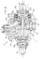
- Numeral 202 designates a housing accommodating an input shaft 203 transmitting torque from the engine (not shown) to a crown gear 205 of a differential 50 of epicyclic kind through bevel gears 204.
- axle shafts 210 and 211 are driven by differential 50.
- Axle shafts 210, 211 have outer end portions 211a, 211b carrying respective outer bodies 212a, 212b of constant-velocity universal joints 213 for driving the vehicle wheels 13a and 13b.
- the crown gear 205 which receives motion M from shaft 203, carries cylindrical toothing 214.
- Toothing 214 engages a gear 215 coupled to a gear 217.
- Both gears 215, 217 are rotatably supported by a shaft 53 coaxial with respect to axle shafts 210 and 211.
- Gear 217 drives an auxiliary gear 220 also coaxial to axle shaft 210, which is integral with a clutch bell member 55.
- Bell member 55 carries the driving discs 226 of two clutches 224, 225 normally released, the driven discs 227 of which are fitted on two drums 230, 231, one 230 force fitted directly to axle shaft 210, the other 231 being force fitted to a hollow shaft 56 coaxial to said axle shaft 210 and integral with spider 57 of differential 50. Spider 57 is in turn connected to the other axle shaft 211.
- Clutch assembly 224, 225 is located in a housing 60 disposed on the outside of housing 202 on the opposite side of differential 50.
- Rams 234, 235 hydraulically operated for controlling the clutches, are fitted within bell member 55.
- the clutches that are used may vary according to design requirements.
- Auxiliary gears 215 is rotated by crown gear 205 through toothing 214.
- Gear 215 rotates transmission shaft 253 which in turn drives gear 217.
- Cylindrical gears 215, 217 are rotatably free with respect to drums 230, 231 while clutches 224 or 225 are released.
- the gear ratio between crown gear 205 and auxiliary gears 220 is kept to the lowest possible value.
- this value will have to be expressly calculated for each kind of vehicle equipped with the differential according to the invention.
Description
- FIG. 1
- is a schematic view of a preferred embodiment of a differential according to the present invention;
- FIG. 2
- is a partial sectional view of the embodiment of FIG. 1;
Claims (3)
- An automobile differential, particularly for four wheel drive vehicles, provided with a system for varying and controlling continuously torque distribution between the wheels of a same axle, of the type comprising an input shaft (203) being adapted for transmitting torque (M) to said axle shafts (210, 211) through a differential (50) provided with a crown gear (205) rotatably coupled to said input shaft (203), where in order to transmit part of the torque, there are provided in series between said crown gear (205) and the end portions of said axle shafts (210, 211) external to the differential (50),:characterized in that one (231) of said drums with the driven discs (227) of said clutches (224,225) connects to one (211) of said two axle shafts through a hollow shaft (56) coaxial to said two axle shafts and integral with the spider (57) of the differential (50), and the other one (230) of said drums is directly connected with the other one (210) of said two axle shafts.a) gearing-up means (215, 217, 220) in driving connection to the crown gear (205), with an auxiliary gear (220) always rotating at a higher speed of said crown (205);b) one clutch (224,225) for each axle shaft (210,211) having bell members (55) with driving discs (226) and drums (230,231) with driven discs 227 for coupling for rotation, said clutches being adapted for transmitting torque from said crown gear to said axle shafts;c) control means (234, 235) for varying the condition of said cluches (224,225) for releasably coupling for rotation, so as to continuously control torque (M) distribution between said axle shafts (210, 211);
- A differential as claimed in claim 1, characterized in that said bell members (55) of said cluches (224,225) are coupled for rotation with the auxiliary gear (220) of said gearing-up means.
- A differential as claimed in claim 1, characterized in that said clutches (224,225) are located outside of the housing (202) of the differential (50).
Applications Claiming Priority (2)
| Application Number | Priority Date | Filing Date | Title |
|---|---|---|---|
| ITTO931007A IT1261136B (en) | 1993-12-29 | 1993-12-29 | ELECTRONICALLY CONTROLLED DIFFERENTIAL FOR MOTOR VEHICLES WITH SYSTEM TO CONTROL THE DIVISION OF THE DRIVING TORQUE. |
| ITTO931007 | 1993-12-29 |
Publications (2)
| Publication Number | Publication Date |
|---|---|
| EP0662402A1 EP0662402A1 (en) | 1995-07-12 |
| EP0662402B1 true EP0662402B1 (en) | 1998-03-11 |
Family
ID=11411980
Family Applications (1)
| Application Number | Title | Priority Date | Filing Date |
|---|---|---|---|
| EP94120782A Expired - Lifetime EP0662402B1 (en) | 1993-12-29 | 1994-12-27 | An electronically controlled differential with a system for controlling torque distribution |
Country Status (4)
| Country | Link |
|---|---|
| EP (1) | EP0662402B1 (en) |
| DE (1) | DE69408961T2 (en) |
| ES (1) | ES2115148T3 (en) |
| IT (1) | IT1261136B (en) |
Cited By (4)
| Publication number | Priority date | Publication date | Assignee | Title |
|---|---|---|---|---|
| WO2005016683A1 (en) | 2003-08-04 | 2005-02-24 | Gkn Driveline International Gmbh | Transmission system |
| WO2005028236A1 (en) * | 2003-09-12 | 2005-03-31 | Gkn Driveline International Gmbh | Gear arrangement |
| US8062162B2 (en) | 2006-09-18 | 2011-11-22 | Magna Steyr Fahrzeugtechnik Ag & Co. Kg | Differential gear unit for motor vehicles having controllable driving power distribution |
| DE102006032369B4 (en) | 2006-07-13 | 2023-05-11 | Linde Material Handling Gmbh | Drive axle with differential gear and braking device |
Families Citing this family (12)
| Publication number | Priority date | Publication date | Assignee | Title |
|---|---|---|---|---|
| US5692987A (en) * | 1994-07-05 | 1997-12-02 | Honda Giken Kogyo Kabushiki Kaisha | Power transmitting system for vehicle |
| GB9926494D0 (en) * | 1999-11-10 | 2000-01-12 | Rover Group | A vehicle yaw control arrangement |
| IT1320394B1 (en) | 2000-06-05 | 2003-11-26 | Fiat Ricerche | SYSTEM FOR THE ACTIVE CONTROL OF A DIFFERENTIAL OF A VEHICLE. |
| DE10317316B4 (en) * | 2003-04-15 | 2005-05-19 | Gkn Driveline International Gmbh | Modular upgradeable differential |
| AT8357U1 (en) * | 2005-04-28 | 2006-06-15 | Magna Drivetrain Ag & Co Kg | DIFFERENTIAL GEAR UNIT WITH ACTIVE CONTROL OF THE MOMENT DISTRIBUTION |
| DE102005023389A1 (en) | 2005-05-21 | 2006-11-23 | Zf Friedrichshafen Ag | Device for setting the transmission capabilities of two frictional switching elements |
| DE102006008236B4 (en) * | 2005-06-01 | 2017-08-10 | Volkswagen Ag | Transmission device of a motor vehicle |
| AT8859U1 (en) * | 2005-09-29 | 2007-01-15 | Magna Steyr Fahrzeugtechnik Ag | DIFFERENTIAL GEARBOX UNIT FOR MOTOR VEHICLES WITH ACTIVE CONTROL OF THE DRIVE POWER DISTRIBUTION |
| DE102007001197B4 (en) * | 2007-01-05 | 2008-10-30 | Magna Powertrain Ag & Co Kg | transmission |
| DE102008039928A1 (en) * | 2008-08-27 | 2010-03-04 | Magna Powertrain Ag & Co Kg | Differential gear unit for use with active control of torque distribution, particularly at front axle of motor vehicle, has input element propelled to rotating motion and differential gear coupled with input element |
| US8070638B2 (en) | 2009-03-30 | 2011-12-06 | GM Global Technology Operations LLC | Dual input planetary final drive |
| DE102022103840A1 (en) | 2022-02-17 | 2023-08-17 | Audi Aktiengesellschaft | Drive device for a vehicle axle of a two-track vehicle |
Family Cites Families (7)
| Publication number | Priority date | Publication date | Assignee | Title |
|---|---|---|---|---|
| JP2641724B2 (en) * | 1988-01-11 | 1997-08-20 | 本田技研工業株式会社 | Left and right wheel drive system for vehicles |
| JPH01154021U (en) * | 1988-04-15 | 1989-10-24 | ||
| US5056614A (en) * | 1989-04-26 | 1991-10-15 | Honda Giken Kogyo Kabushiki Kaisha | Apparatus for controlling the distribution of drive power for motor vehicles |
| JPH03525A (en) * | 1989-05-30 | 1991-01-07 | Honda Motor Co Ltd | Distribution control device for drive force for front and rear wheel drive car |
| DE69222739T2 (en) * | 1991-11-29 | 1998-05-14 | Mitsubishi Motors Corp | Control system for power distribution for vehicles |
| IT1250886B (en) * | 1991-12-20 | 1995-04-21 | Fiat Ricerche | SYSTEM FOR THE CONTROL OF THE DISTRIBUTION OF THE DRIVING TORQUE BETWEEN THE WHEELS OF THE SAME AXLE OF A VEHICLE. |
| JP2738225B2 (en) * | 1992-06-15 | 1998-04-08 | 三菱自動車工業株式会社 | Left and right driving force adjustment device for vehicles |
-
1993
- 1993-12-29 IT ITTO931007A patent/IT1261136B/en active IP Right Grant
-
1994
- 1994-12-27 EP EP94120782A patent/EP0662402B1/en not_active Expired - Lifetime
- 1994-12-27 DE DE69408961T patent/DE69408961T2/en not_active Expired - Lifetime
- 1994-12-27 ES ES94120782T patent/ES2115148T3/en not_active Expired - Lifetime
Cited By (5)
| Publication number | Priority date | Publication date | Assignee | Title |
|---|---|---|---|---|
| WO2005016683A1 (en) | 2003-08-04 | 2005-02-24 | Gkn Driveline International Gmbh | Transmission system |
| WO2005028236A1 (en) * | 2003-09-12 | 2005-03-31 | Gkn Driveline International Gmbh | Gear arrangement |
| JP2007505276A (en) * | 2003-09-12 | 2007-03-08 | ゲー カー エヌ ドライブライン インターナショナル ゲゼルシャフト ミット ベシュレンクテル ハフツング | Transmission assembly |
| DE102006032369B4 (en) | 2006-07-13 | 2023-05-11 | Linde Material Handling Gmbh | Drive axle with differential gear and braking device |
| US8062162B2 (en) | 2006-09-18 | 2011-11-22 | Magna Steyr Fahrzeugtechnik Ag & Co. Kg | Differential gear unit for motor vehicles having controllable driving power distribution |
Also Published As
| Publication number | Publication date |
|---|---|
| EP0662402A1 (en) | 1995-07-12 |
| ITTO931007A1 (en) | 1995-06-29 |
| ES2115148T3 (en) | 1998-06-16 |
| ITTO931007A0 (en) | 1993-12-29 |
| DE69408961T2 (en) | 1998-07-02 |
| DE69408961D1 (en) | 1998-04-16 |
| IT1261136B (en) | 1996-05-09 |
Similar Documents
| Publication | Publication Date | Title |
|---|---|---|
| EP0662402B1 (en) | An electronically controlled differential with a system for controlling torque distribution | |
| US6827663B2 (en) | Differential gear | |
| EP0262434B1 (en) | Interaxle differential restriction device for vehicle four wheel drive systems | |
| US5226860A (en) | Vehicle torque transfer case | |
| EP0315200B1 (en) | Power transmission apparatus | |
| US5860889A (en) | Tandem forward rear axle lockout | |
| EP0396323B1 (en) | Torque distribution control system for a four-wheel drive motor vehicle | |
| US5711389A (en) | Tandem rear drive axle assembly | |
| US20020111245A1 (en) | Power on demand differential | |
| GB2267322A (en) | Differential gearing unit | |
| US4875978A (en) | Vehicle four wheel drive system | |
| US5314039A (en) | Drive assembly for a four wheel drive vehicle, having a disconnectable viscous coupling | |
| EP0876933B1 (en) | Adapter for transfer cases | |
| CA1294560C (en) | Four wheel drive vehicle | |
| JP2005511996A (en) | Active torque bias fitting | |
| US4923029A (en) | Drive means for all-wheel-driven motor vehicles | |
| EP0423568B1 (en) | A disengageable four-wheel-drive transmission system for motor vehicles | |
| US4790211A (en) | Power transmission device for four wheel drive vehicle having an improved differential motion limiting mechanism | |
| EP0290201B1 (en) | Power transmitting system for a four-wheel drive vehicle | |
| US4050328A (en) | Four-wheel drive vehicle with drive transfer gear assembly | |
| EP0984870B1 (en) | Transmission for four-wheel drive vehicle | |
| JP3047016B2 (en) | Front and rear wheel drive force distribution device | |
| US4756209A (en) | Drive power transmission device | |
| JPH09136555A (en) | Power transmission of four-wheel drive | |
| JPH0725269B2 (en) | Rear wheel torque distribution control device for vehicle |
Legal Events
| Date | Code | Title | Description |
|---|---|---|---|
| PUAI | Public reference made under article 153(3) epc to a published international application that has entered the european phase |
Free format text: ORIGINAL CODE: 0009012 |
|
| AK | Designated contracting states |
Kind code of ref document: A1 Designated state(s): DE ES FR GB SE |
|
| 17P | Request for examination filed |
Effective date: 19950713 |
|
| 17Q | First examination report despatched |
Effective date: 19960227 |
|
| RAP1 | Party data changed (applicant data changed or rights of an application transferred) |
Owner name: CENTRO RICERCHE FIAT SOCIETA CONSORTILE PER AZIONI |
|
| GRAG | Despatch of communication of intention to grant |
Free format text: ORIGINAL CODE: EPIDOS AGRA |
|
| GRAG | Despatch of communication of intention to grant |
Free format text: ORIGINAL CODE: EPIDOS AGRA |
|
| GRAH | Despatch of communication of intention to grant a patent |
Free format text: ORIGINAL CODE: EPIDOS IGRA |
|
| GRAH | Despatch of communication of intention to grant a patent |
Free format text: ORIGINAL CODE: EPIDOS IGRA |
|
| GRAA | (expected) grant |
Free format text: ORIGINAL CODE: 0009210 |
|
| AK | Designated contracting states |
Kind code of ref document: B1 Designated state(s): DE ES FR GB SE |
|
| REF | Corresponds to: |
Ref document number: 69408961 Country of ref document: DE Date of ref document: 19980416 |
|
| REG | Reference to a national code |
Ref country code: ES Ref legal event code: FG2A Ref document number: 2115148 Country of ref document: ES Kind code of ref document: T3 |
|
| ET | Fr: translation filed | ||
| PLBE | No opposition filed within time limit |
Free format text: ORIGINAL CODE: 0009261 |
|
| STAA | Information on the status of an ep patent application or granted ep patent |
Free format text: STATUS: NO OPPOSITION FILED WITHIN TIME LIMIT |
|
| 26N | No opposition filed | ||
| REG | Reference to a national code |
Ref country code: GB Ref legal event code: IF02 |
|
| PGFP | Annual fee paid to national office [announced via postgrant information from national office to epo] |
Ref country code: ES Payment date: 20081216 Year of fee payment: 15 |
|
| PGFP | Annual fee paid to national office [announced via postgrant information from national office to epo] |
Ref country code: SE Payment date: 20081204 Year of fee payment: 15 |
|
| PGFP | Annual fee paid to national office [announced via postgrant information from national office to epo] |
Ref country code: GB Payment date: 20081222 Year of fee payment: 15 |
|
| EUG | Se: european patent has lapsed | ||
| GBPC | Gb: european patent ceased through non-payment of renewal fee |
Effective date: 20091227 |
|
| PG25 | Lapsed in a contracting state [announced via postgrant information from national office to epo] |
Ref country code: GB Free format text: LAPSE BECAUSE OF NON-PAYMENT OF DUE FEES Effective date: 20091227 |
|
| REG | Reference to a national code |
Ref country code: ES Ref legal event code: FD2A Effective date: 20110329 |
|
| PG25 | Lapsed in a contracting state [announced via postgrant information from national office to epo] |
Ref country code: SE Free format text: LAPSE BECAUSE OF NON-PAYMENT OF DUE FEES Effective date: 20091228 |
|
| PG25 | Lapsed in a contracting state [announced via postgrant information from national office to epo] |
Ref country code: ES Free format text: LAPSE BECAUSE OF NON-PAYMENT OF DUE FEES Effective date: 20110316 |
|
| PG25 | Lapsed in a contracting state [announced via postgrant information from national office to epo] |
Ref country code: ES Free format text: LAPSE BECAUSE OF NON-PAYMENT OF DUE FEES Effective date: 20091228 |
|
| PGFP | Annual fee paid to national office [announced via postgrant information from national office to epo] |
Ref country code: DE Payment date: 20131224 Year of fee payment: 20 |
|
| PGFP | Annual fee paid to national office [announced via postgrant information from national office to epo] |
Ref country code: FR Payment date: 20131209 Year of fee payment: 20 |
|
| REG | Reference to a national code |
Ref country code: DE Ref legal event code: R071 Ref document number: 69408961 Country of ref document: DE |