EP0661840A2 - Viterbi decoder using decreasing length tracebacks - Google Patents
Viterbi decoder using decreasing length tracebacks Download PDFInfo
- Publication number
- EP0661840A2 EP0661840A2 EP94309106A EP94309106A EP0661840A2 EP 0661840 A2 EP0661840 A2 EP 0661840A2 EP 94309106 A EP94309106 A EP 94309106A EP 94309106 A EP94309106 A EP 94309106A EP 0661840 A2 EP0661840 A2 EP 0661840A2
- Authority
- EP
- European Patent Office
- Prior art keywords
- traceback
- symbol
- length
- array
- branch data
- Prior art date
- Legal status (The legal status is an assumption and is not a legal conclusion. Google has not performed a legal analysis and makes no representation as to the accuracy of the status listed.)
- Withdrawn
Links
Images


Classifications
-
- H—ELECTRICITY
- H03—ELECTRONIC CIRCUITRY
- H03M—CODING; DECODING; CODE CONVERSION IN GENERAL
- H03M13/00—Coding, decoding or code conversion, for error detection or error correction; Coding theory basic assumptions; Coding bounds; Error probability evaluation methods; Channel models; Simulation or testing of codes
- H03M13/37—Decoding methods or techniques, not specific to the particular type of coding provided for in groups H03M13/03 - H03M13/35
- H03M13/39—Sequence estimation, i.e. using statistical methods for the reconstruction of the original codes
- H03M13/3961—Arrangements of methods for branch or transition metric calculation
-
- H—ELECTRICITY
- H03—ELECTRONIC CIRCUITRY
- H03M—CODING; DECODING; CODE CONVERSION IN GENERAL
- H03M13/00—Coding, decoding or code conversion, for error detection or error correction; Coding theory basic assumptions; Coding bounds; Error probability evaluation methods; Channel models; Simulation or testing of codes
- H03M13/37—Decoding methods or techniques, not specific to the particular type of coding provided for in groups H03M13/03 - H03M13/35
- H03M13/39—Sequence estimation, i.e. using statistical methods for the reconstruction of the original codes
- H03M13/41—Sequence estimation, i.e. using statistical methods for the reconstruction of the original codes using the Viterbi algorithm or Viterbi processors
- H03M13/4161—Sequence estimation, i.e. using statistical methods for the reconstruction of the original codes using the Viterbi algorithm or Viterbi processors implementing path management
- H03M13/4169—Sequence estimation, i.e. using statistical methods for the reconstruction of the original codes using the Viterbi algorithm or Viterbi processors implementing path management using traceback
-
- H—ELECTRICITY
- H04—ELECTRIC COMMUNICATION TECHNIQUE
- H04L—TRANSMISSION OF DIGITAL INFORMATION, e.g. TELEGRAPHIC COMMUNICATION
- H04L1/00—Arrangements for detecting or preventing errors in the information received
- H04L1/004—Arrangements for detecting or preventing errors in the information received by using forward error control
- H04L1/0045—Arrangements at the receiver end
- H04L1/0054—Maximum-likelihood or sequential decoding, e.g. Viterbi, Fano, ZJ algorithms
Definitions
- This invention relates generally to radio transmission such as digital cellular telephony and particularly to decrementing the length of tracebacks in a Viterbi decoder.
- Time division multiple access encoded information is transmitted in multiple channels per carrier.
- GSM Group Special Mobile
- a Viterbi decoder is a maximum likelihood decoder that provides forward error correction. Viterbi decoders are used to decode a sequence of encoded symbols, such as a bit stream.
- the bit stream can represent encoded information in a telecommunication system. Such information can be transmitted through various media with each bit (or set of bits) representing a symbol instant.
- the Viterbi decoder works back through a sequence of possible bit sequences at each symbol instant to determine which one bit sequence is most likely to have been transmitted.
- the possible transitions from a bit at one symbol instant, or state, to a bit at a next, subsequent, symbol instant or state is limited. Each possible transition from one state to a next state can be shown graphically and is defined as a branch.
- a sequence of interconnected branches is defined as a path.
- Each state can transition only to a limited number of next states upon receipt of the next bit in the bit stream. Thus, some paths survive and other paths do not survive during the decoding process. By eliminating those transitions that are not permissible, computational efficiency can be increased in determining the most likely paths to survive.
- the Viterbi decoder typically defines and calculates a branch metric associated with each branch and employs this branch metric to determine which paths survive and which paths do not survive.
- a branch metric is calculated at each symbol instant for each possible branch.
- Each path has an associated metric, accumulated cost, that is updated at each symbol instant.
- the accumulated cost for the next state is calculated as the lesser of the sum of the branch metric for the possible transitions and the path accumulated cost at the previous state.
- a communication system and a method for tracing a path through an array of storage registers containing surviving branch data obtains a decoded symbol.
- the method includes initiating a first traceback from a storage register at a first symbol instant.
- the traceback traces a path back through the array a first predetermined number of symbol instants to obtain a first decoded symbol.
- the length of the traceback is changed and another traceback is executed. This process is repeated until all remaining decoded symbols are obtained.
- the traceback length is repeatedly decremented by one less than the constraint length, with each traceback obtaining multiple decoded symbols.
- Transceiver 10 shown in the block diagram of Figure 1, is an illustrative embodiment of the invention.
- Transceiver 10 is a communication system, or portion of a communication system, such as a mobile digital cellular telephone.
- Transceiver 10 is comprised of a transmitter 12 and receiver 14.
- Transmitter 12 transmits signals; receiver 14 receives signals for decoding.
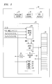
- FIG. 2 is a partial block diagram of a transceiver 10, shown in more detail.
- Transceiver 10 includes a digital signal processor (DSP) 20 having an error correction coprocessor 30.
- Error correction coprocessor 30 may be embedded in DSP 20.
- Some of the registers of random access memory (RAM) of DSP 20 are allocated as a traceback RAM 28. Alternatively, dedicated RAM could be provided. Traceback RAM 28 may be accessible to both DSP 20 and coprocessor 30.
- DSP digital signal processor
- RAM random access memory
- An indirect addressing technique is used to write data to and read data from the coprocessor 30.
- the address is transferred to the coprocessor and translated to the address of a corresponding register in the coprocessor 30.
- the data at the addressed coprocessor register is read by reading data register 26 of DSP 20. Instructions are passed to the coprocessor by writing an instruction into the instruction register 22.
- the branch metric unit 154 provides two branch metric values, BMO and BM1, per individual state to update unit 32.
- the branch metric values are utilized as is known in the art to update the accumulated cost.
- Update unit 32 provides to traceback unit 36 the minimum accumulated cost which is stored in the minimum accumulated cost (MAC) register 42. Update unit 32 also provides the address of the register in traceback RAM 28 in which the minimum accumulated cost has occurred, and stores that address in MIDX register 40.
- MAC minimum accumulated cost
- Traceback unit 36 provides individual state information defining the minimum accumulated cost path through the array of registers, as well as soft decision confidence level in decoded symbols, to traceback RAM 28.
- update unit 32 also provides a decoded symbol to DSP 20 by way of decoded symbol register (DSR) 34.
- DSR decoded symbol register
- Traceback length register (TBLR) 38 is the register in which the traceback length is stored. The traceback length can be changed by overwriting the existing traceback length stored in TBLR 38. In this manner, the traceback length is programmable.
- a traceback initiated by a traceback instruction to coprocessor 30 from DSP 20, can be executed with a traceback length that is different than the traceback length of previous or subsequent tracebacks.
- An update instruction from the DSP causes another cell of traceback RAM to be filled as the array of registers is being filled with surviving branch data. Tracebacks can be executed between two update instructions or even after an update instruction when there are no more symbols to update. Multiple tracebacks may be executed at a single symbol instant.
- the transmission burst contains a predetermined number of bits.
- Each frame includes starting bits 102, a first set of information bits 104, training bits 106, a second set of information bits 108 and ending bits 110.
- the training bits are also known.
- the starting and ending bits are known and typically are zeros.
- Figure 4 shows a matrix representation of surviving branch data stored in an array of storage registers, in traceback RAM 28, that is useful in understanding the traceback operation in a Viterbi decoder.
- a maximum likelihood path that provides the maximum likelihood sequence estimates is shown overlaid on the matrix representation.
- At each state or symbol instant there are a number of states (shown vertically) that range from zero up to 2 c - 1- 1, where C is the constraint length. These states are referred to as individual states.
- the matrix shown in Figure 4 is constructed one symbol instant at a time, as is known in the art.
- the matrix entries at each symbol instant comprise a cell.
- a single update instruction from DSP 20 to coprocessor 30 initiates an update operation by update unit 32 to produce a cell of matrix entries.
- each individual state of the illustrative embodiment shown in Figure 4 can only transition to two possible individual states at the next symbol instant. Concomitantly, each individual state at the next symbol instant has only two possible previous individual states from which a transition to it can originate. Other decoders could have more than two transitions to a next state or from a previous state.
- a branch metric is calculated at each symbol instant for each possible transition from an individual state at one symbol instant to an individual state at the next symbol instant.
- Various methods for calculating branch metrics are known in the art.
- the branch metric of both branches transitioning to a given next individual state are calculated, then added to the accumulated cost of the respective originating individual state. This results in two potential accumulated cost sums.
- a comparison is made of the two potential accumulated cost sums.
- An extremum branch metric such as the lesser of the two sums, is selected as the next state accumulated cost.
- a transition corresponding to the lesser sum is the more likely transition from the two possible originating individual states to the given next individual state.
- the originating individual state of the more likely transition is stored in traceback RAM 28 (forming the matrix of Figure 4) as the surviving branch to the given next individual state, as is known in the art
- the lesser sum is the accumulated cost of the next individual state. This process is repeated for each of the next individual states and repeated also for each symbol instant until all of the symbols in the bit stream are decoded.
- Traceback RAM 28 can be addressed using modulo addressing. This results in a finite length array appearing to be circular.
- a traceback of length 60 initiated from symbol instant 30 in an array having 64 symbol instants designated 1 through 64. The traceback starts in symbol instant 30, traces back through symbol instants 29, 28, 27 down through symbol instant 1, symbol instant 64, 63, 62 and so forth until reaching symbol instant 34.
- symbol instant 34 the individual state associated with the minimum accumulated cost is translated into a decoded symbol.
- the decoded symbol at each symbol instant can be obtained by waiting until the matrix of surviving branch data is complete. Then, starting with the individual state in the last symbol instant having the minimum associated accumulated cost, tracing back through the matrix once. At each symbol instant of this traceback, the originating individual state is translated into a decoded symbol for that symbol instant as is known in the art.
- a predetermined length traceback operation can be initiated to obtain a decoded symbol at a previous symbol instant.
- the previous symbol instant will precede the symbol instant at which the traceback is initiated, the present symbol instant, by the traceback length.
- DSP 20 alternates instructions between update and traceback. Each update constructs one more cell in the matrix. Each traceback decodes a symbol and provides the decoded symbol to DSP 20 by way of DSR 34. After all updates are complete, the update instruction is omitted and subsequent tracebacks decode the remaining symbols. Each time a symbol instant increases, another traceback operation will provide another decoded symbol.
- FIG. 5 An example is shown in Figure 5 in which the traceback length for each symbol instant is shown.
- a first traceback length is written to traceback length register 38.
- a traceback having the first traceback length is executed.
- a single instruction from DSP 20 to coprocessor 30 initiates a traceback by traceback unit 36.
- the initial traceback length may very short, for example 1.
- the traceback may cycle into portions of the trellis having surviving branch data from a previous transmission burst. The decoded symbol at the end of this traceback is typically discarded.
- Subsequent tracebacks may be executed having the same traceback length by repeated instructions to the traceback unit.
- the decoded symbol at the end of each such traceback is typically discarded. Executing a traceback having a very short traceback length where the decoded symbol is discarded minimizes the resources of time and energy expended in generating a symbol that is not used.
- the traceback length may be changed to a second traceback length. This is achieved by overwriting traceback length register 38 with the second traceback length.
- the second traceback length is substantially greater than the first traceback length. Longer traceback lengths provide greater accuracy in determining a decoded symbol.
- a traceback having a second traceback length is initiated from the predetermined symbol instant.
- a traceback of length 31 can be initiated. This traceback results in a final decoded symbol for symbol instant 1.
- the traceback length is either maintained at the second traceback length, or changed to a shorter traceback length.
- Figure 5 shows the traceback length maintained at the second traceback length through symbol instant N, here 64.
- a traceback having the second traceback length results in a final decoded symbol as described above.
- a traceback of length 31 initiated in symbol instant 33 results in a final decoded symbol in symbol instant 2.
- a traceback of length 31 initiated in symbol instant 34 results in a final decoded symbol in symbol instant 3. This process continues through symbol instant N.
- the matrix of surviving branch data in traceback RAM 28 is complete.
- a traceback having a traceback of 31 initiated from symbol instant 64 results in a final decoded symbol in symbol instant 33.
- the traceback instruction is executed repeatedly.
- the number of times the traceback instruction is repeatedly executed corresponds to the number of units the traceback length is long, here 31.
- the traceback length is changed, such as being decremented by one as shown in Figure 5.
- the repeated traceback length decrements can be achieved by overwriting the traceback length register 38 or the traceback unit 36 can automatically decrement the traceback length and write the decremented traceback length value to traceback length register 38.
- the repeated execution of a traceback instruction can execute various length tracebacks in any order to obtain the remaining final symbols.
- a series of tracebacks are initiated having traceback lengths where k is the second traceback length.
- Each traceback traces a path back through the matrix array of storage registers of surviving branch data to determine a decoded symbol.
- the final decoded symbols for symbol instants 34 through N may be obtained without executing a traceback of each length from the second traceback length through one, inclusive.
- a shift register 200 shown in Figure 6, is utilized. The number of stages in shift register 200 is n.
- a traceback is executed.
- An exemplary traceback length is 31.
- the maximum likelihood sequence bit for each symbol instant is sequentially shifted into shift register 200.
- the last C-1 bits of the maximum likelihood sequence bits are transferred to the traceback register (TBR) 202, right aligned as shown in Figure 6.
- the (n-(c-1)) upper bits of shift register 200 may be masked to zero upon transfer to TBR 202.
- n decoded symbols are transferred to TBR 202, and the traceback length can be decreased by n.
- the least significant bit in traceback register 202 is the decoded symbol for the previous symbol instant determined by the traceback. In other words, it is the decoded symbol for symbol instant 33.
- the next bit is the decoded symbol for the next subsequent symbol instant, 34.
- the third bit is the decoded symbol for symbol instant 35.
- Other implementations might provide a different order.
- the length of the traceback is decremented by (C-1), to 28, and another traceback is executed.
- This traceback obtains decoded symbols for the next (C-1) symbol instants, 36, 37 and 38.
- the process is repreated until a decoded symbol has been obtained for all N symbol instants.
- the last traceback may obtain fewer than (C-1) decoded symbols.
- the traceback length can be decremented by overwriting the present traceback length in TBLR 38, or by setting a counter to automatically decrement the traceback length following each traceback.
- a benefit of using shift register 200 and traceback register 202 can be seen in Figure 5 where decreasing the traceback length in steps of two is shown at 204 and steps of three is shown at 206 for comparison to the individual decrement shown without a reference numeral. Fewer tracebacks are required to obtain the decoded symbols for the remaining symbol instants once the array is complete.
- a series of tracebacks can be initiated having traceback lengths k-m, where m can take on values greater than unity, such as c-1 or n.
- RAM 28 may contain hard decision or soft decision data.
- Hard decision data may be stored with sixteen hard decisions per 16 bit word.
- Soft decisions may be stored with two soft decisions per sixteen bit word.
- the invention is particularly useful in communication systems and equipment employing integrated circuits including this technique.
- Such communications systems and equipment have the advantage of maintaining a long traceback length to provide increased accuracy in the decoding process, then decrementing the traceback length using various techniques until all symbols are decoded.
- Pipelining is achieved by initiating computation with a new data set before completing computations with a previous set of data. The more latches used in pipelining, the greater the depth of pipelining. Pipelining causes an initial latency in computation time required to fill the pipeline, but maximizes usage of resources such as adders and subtracters.
Landscapes
- Physics & Mathematics (AREA)
- Probability & Statistics with Applications (AREA)
- Engineering & Computer Science (AREA)
- Theoretical Computer Science (AREA)
- Artificial Intelligence (AREA)
- Computer Networks & Wireless Communication (AREA)
- Signal Processing (AREA)
- Error Detection And Correction (AREA)
- Digital Transmission Methods That Use Modulated Carrier Waves (AREA)
- Time-Division Multiplex Systems (AREA)
Abstract
Description
- This invention relates generally to radio transmission such as digital cellular telephony and particularly to decrementing the length of tracebacks in a Viterbi decoder.
- Time division multiple access encoded information is transmitted in multiple channels per carrier. In accordance with the Group Special Mobile (GSM) standard, there are eight channels per carrier. Each channel is provided a time period for transmission called a transmission burst. Some of the bits in each transmission burst are set aside as training bits for system use.
- A Viterbi decoder is a maximum likelihood decoder that provides forward error correction. Viterbi decoders are used to decode a sequence of encoded symbols, such as a bit stream. The bit stream can represent encoded information in a telecommunication system. Such information can be transmitted through various media with each bit (or set of bits) representing a symbol instant. In the decoding process, the Viterbi decoder works back through a sequence of possible bit sequences at each symbol instant to determine which one bit sequence is most likely to have been transmitted. The possible transitions from a bit at one symbol instant, or state, to a bit at a next, subsequent, symbol instant or state is limited. Each possible transition from one state to a next state can be shown graphically and is defined as a branch. A sequence of interconnected branches is defined as a path. Each state can transition only to a limited number of next states upon receipt of the next bit in the bit stream. Thus, some paths survive and other paths do not survive during the decoding process. By eliminating those transitions that are not permissible, computational efficiency can be increased in determining the most likely paths to survive. The Viterbi decoder typically defines and calculates a branch metric associated with each branch and employs this branch metric to determine which paths survive and which paths do not survive.
- A branch metric is calculated at each symbol instant for each possible branch. Each path has an associated metric, accumulated cost, that is updated at each symbol instant. For each possible transition, the accumulated cost for the next state is calculated as the lesser of the sum of the branch metric for the possible transitions and the path accumulated cost at the previous state.
- While several paths survive the transition from one symbol instant to the next symbol instant, there is only one minimum accumulated cost path from the least of the minimum accumulated costs at a symbol instant, back through the possible branches. Surviving branch data at sequential symbol instants is stored in an array. Identifying the minimum accumulated cost path through the surviving branch data starting with a given symbol instant and extending through previous symbol instants is referred to as a traceback. Typical prior art applications employed a single traceback. The number of symbol instants back through the array that the minimum accumulated cost path extends is the length, or depth, of the traceback. The individual state in the array associated with the minimum accumulated cost at the end of the traceback is translated into the most likely bit to have been transmitted in that symbol instant. This is referred to as a decoded symbol. The longer the traceback length, the greater the accuracy in determining a decoded symbol.
- At each symbol instant during the construction of a matrix of surviving branch data, an update operation is followed by a traceback. A latency of symbol instants equal to the traceback length occurs before a valid decoded symbol is obtained. The traceback typically has a fixed length. When the matrix of surviving branch data is complete, it is necessary to obtain the remaining decoded symbols, equal in number to the traceback length, from the matrix. A need remains in the art for a technique to obtain the remaining decoded symbols after the matrix of surviving branch data is complete.
- In accordance with one aspect of the invention, a communication system and a method for tracing a path through an array of storage registers containing surviving branch data is disclosed. The traceback obtains a decoded symbol. The method includes initiating a first traceback from a storage register at a first symbol instant. The traceback traces a path back through the array a first predetermined number of symbol instants to obtain a first decoded symbol. The length of the traceback is changed and another traceback is executed. This process is repeated until all remaining decoded symbols are obtained.
- In an alternate embodiment, the traceback length is repeatedly decremented by one less than the constraint length, with each traceback obtaining multiple decoded symbols.
- The invention will be described by way of an example with reference to the drawings, in which:
- Figure 1 is a block diagram of a transceiver, in accordance with an illustrative embodiment of the present invention;
- Figure 2 is a partial block diagram of a transceiver showing digital signal processor having an error correction coprocessor;
- Figure 3 is an illustration showing the structure of bits in an exemplary transmission burst;
- Figure 4 is a matrix representation of surviving branch data stored in an array of storage registers useful in describing the present invention;
- Figure 5 is an illustration of tracebacks of decrementing lengths, initiated at a single symbol instant; and
- Figure 6 is an illustration showing a variable length shift register.
-
Transceiver 10 shown in the block diagram of Figure 1, is an illustrative embodiment of the invention. Transceiver 10 is a communication system, or portion of a communication system, such as a mobile digital cellular telephone. Transceiver 10 is comprised of atransmitter 12 andreceiver 14.Transmitter 12 transmits signals;receiver 14 receives signals for decoding. - Figure 2 is a partial block diagram of a
transceiver 10, shown in more detail. Transceiver 10 includes a digital signal processor (DSP) 20 having anerror correction coprocessor 30.Error correction coprocessor 30 may be embedded in DSP 20. Some of the registers of random access memory (RAM) ofDSP 20 are allocated as atraceback RAM 28. Alternatively, dedicated RAM could be provided.Traceback RAM 28 may be accessible to both DSP 20 andcoprocessor 30. - An indirect addressing technique is used to write data to and read data from the
coprocessor 30. To write data to a register at an address incoprocessor 30, an address is written to addressregister 24 and the data is written todata register 26. The address is transferred fromDSP 20 to an address generator incoprocessor 30 and is translated into the address of a corresponding register. To read data from a register at an address incoprocessor 30, an address is written intoaddress register 24 ofDSP 20. The address is transferred to the coprocessor and translated to the address of a corresponding register in thecoprocessor 30. The data at the addressed coprocessor register is read by reading data register 26 ofDSP 20. Instructions are passed to the coprocessor by writing an instruction into theinstruction register 22. - In the above manner, the complex received signals ZI and ZQ, complex tap weights HI(n) and HQ(n), n = 1, 2, ... 5, soft symbols So through S5 and generating polynomials Go through G5 are provided as inputs of the branch
metric unit 154 withincoprocessor 30. The branchmetric unit 154 provides two branch metric values, BMO and BM1, per individual state to updateunit 32. The branch metric values are utilized as is known in the art to update the accumulated cost. -
Update unit 32 provides to tracebackunit 36 the minimum accumulated cost which is stored in the minimum accumulated cost (MAC)register 42.Update unit 32 also provides the address of the register intraceback RAM 28 in which the minimum accumulated cost has occurred, and stores that address inMIDX register 40. -
Traceback unit 36 provides individual state information defining the minimum accumulated cost path through the array of registers, as well as soft decision confidence level in decoded symbols, to tracebackRAM 28. At the end of a traceback,update unit 32 also provides a decoded symbol toDSP 20 by way of decoded symbol register (DSR) 34. - Traceback length register (TBLR) 38 is the register in which the traceback length is stored. The traceback length can be changed by overwriting the existing traceback length stored in
TBLR 38. In this manner, the traceback length is programmable. A traceback, initiated by a traceback instruction to coprocessor 30 fromDSP 20, can be executed with a traceback length that is different than the traceback length of previous or subsequent tracebacks. An update instruction from the DSP causes another cell of traceback RAM to be filled as the array of registers is being filled with surviving branch data. Tracebacks can be executed between two update instructions or even after an update instruction when there are no more symbols to update. Multiple tracebacks may be executed at a single symbol instant. - An exemplary frame, or transmission burst, 100 of information transmitted, typically by a base station or mobile digital cellular telephone to the other, is shown in Figure 3. The transmission burst contains a predetermined number of bits. Each frame includes starting
bits 102, a first set ofinformation bits 104,training bits 106, a second set ofinformation bits 108 and endingbits 110. In an exemplary embodiment, there are three starting and ending bits, 58 bits in each set of information bits, and 26 training bits, for a total of 148 bits per frame. The training bits are also known. The starting and ending bits are known and typically are zeros. - Figure 4 shows a matrix representation of surviving branch data stored in an array of storage registers, in
traceback RAM 28, that is useful in understanding the traceback operation in a Viterbi decoder. A maximum likelihood path that provides the maximum likelihood sequence estimates is shown overlaid on the matrix representation. There are N states or symbol instants (shown horizontally); as an example, Figure 4 illustrates an N of 64. At each state or symbol instant, there are a number of states (shown vertically) that range from zero up to 2c-1-1, where C is the constraint length. These states are referred to as individual states. The matrix shown in Figure 4 is constructed one symbol instant at a time, as is known in the art. The matrix entries at each symbol instant comprise a cell. A single update instruction fromDSP 20 tocoprocessor 30 initiates an update operation byupdate unit 32 to produce a cell of matrix entries. At each symbol instant, each individual state of the illustrative embodiment shown in Figure 4 can only transition to two possible individual states at the next symbol instant. Concomitantly, each individual state at the next symbol instant has only two possible previous individual states from which a transition to it can originate. Other decoders could have more than two transitions to a next state or from a previous state. - A branch metric is calculated at each symbol instant for each possible transition from an individual state at one symbol instant to an individual state at the next symbol instant. Various methods for calculating branch metrics are known in the art. The branch metric of both branches transitioning to a given next individual state are calculated, then added to the accumulated cost of the respective originating individual state. This results in two potential accumulated cost sums. A comparison is made of the two potential accumulated cost sums. An extremum branch metric, such as the lesser of the two sums, is selected as the next state accumulated cost. A transition corresponding to the lesser sum is the more likely transition from the two possible originating individual states to the given next individual state. The originating individual state of the more likely transition is stored in traceback RAM 28 (forming the matrix of Figure 4) as the surviving branch to the given next individual state, as is known in the art The lesser sum is the accumulated cost of the next individual state. This process is repeated for each of the next individual states and repeated also for each symbol instant until all of the symbols in the bit stream are decoded.
-
Traceback RAM 28 can be addressed using modulo addressing. This results in a finite length array appearing to be circular. Consider a traceback oflength 60 initiated from symbol instant 30 in an array having 64 symbol instants designated 1 through 64. The traceback starts insymbol instant 30, traces back throughsymbol instants symbol instant 1,symbol instant symbol instant 34. Atsymbol instant 34, the individual state associated with the minimum accumulated cost is translated into a decoded symbol. - The decoded symbol at each symbol instant can be obtained by waiting until the matrix of surviving branch data is complete. Then, starting with the individual state in the last symbol instant having the minimum associated accumulated cost, tracing back through the matrix once. At each symbol instant of this traceback, the originating individual state is translated into a decoded symbol for that symbol instant as is known in the art.
- Alternatively at each symbol instant during the construction of the matrix of surviving branch data, a predetermined length traceback operation can be initiated to obtain a decoded symbol at a previous symbol instant. The previous symbol instant will precede the symbol instant at which the traceback is initiated, the present symbol instant, by the traceback length. As the traceback RAM is filled with surviving branch data,
DSP 20 alternates instructions between update and traceback. Each update constructs one more cell in the matrix. Each traceback decodes a symbol and provides the decoded symbol toDSP 20 by way ofDSR 34. After all updates are complete, the update instruction is omitted and subsequent tracebacks decode the remaining symbols. Each time a symbol instant increases, another traceback operation will provide another decoded symbol. - In this manner, for a constant length traceback, a series of decoded symbols at sequential symbol instants are obtained. The initial tracebacks decode symbols that are considered invalid, and therefore are discarded. After a latency of symbol instants equal to the traceback length the decoded symbols are considered valid.
- An example is shown in Figure 5 in which the traceback length for each symbol instant is shown. A first traceback length is written to
traceback length register 38. As the matrix of surviving branch data is formed, a traceback having the first traceback length is executed. A single instruction fromDSP 20 tocoprocessor 30 initiates a traceback bytraceback unit 36. The initial traceback length may very short, for example 1. The traceback may cycle into portions of the trellis having surviving branch data from a previous transmission burst. The decoded symbol at the end of this traceback is typically discarded. - Subsequent tracebacks may be executed having the same traceback length by repeated instructions to the traceback unit. The decoded symbol at the end of each such traceback is typically discarded. Executing a traceback having a very short traceback length where the decoded symbol is discarded minimizes the resources of time and energy expended in generating a symbol that is not used.
- At a predetermined symbol instant during construction of the trellis, the traceback length may be changed to a second traceback length. This is achieved by overwriting
traceback length register 38 with the second traceback length. Typically, the second traceback length is substantially greater than the first traceback length. Longer traceback lengths provide greater accuracy in determining a decoded symbol. A traceback having a second traceback length is initiated from the predetermined symbol instant. - For example, in symbol instant 32 a traceback of
length 31 can be initiated. This traceback results in a final decoded symbol forsymbol instant 1. Atsymbol instant 33 and subsequent symbol instants, the traceback length is either maintained at the second traceback length, or changed to a shorter traceback length. Figure 5 shows the traceback length maintained at the second traceback length through symbol instant N, here 64. - At each symbol instant a traceback having the second traceback length results in a final decoded symbol as described above. A traceback of
length 31 initiated insymbol instant 33 results in a final decoded symbol insymbol instant 2. A traceback oflength 31 initiated insymbol instant 34 results in a final decoded symbol insymbol instant 3. This process continues through symbol instant N. After an update instruction atsymbol instant 64, the matrix of surviving branch data intraceback RAM 28 is complete. A traceback having a traceback of 31 initiated from symbol instant 64 results in a final decoded symbol insymbol instant 33. - To obtain final decoded symbols for
symbol instants 34 through N, the traceback instruction is executed repeatedly. The number of times the traceback instruction is repeatedly executed corresponds to the number of units the traceback length is long, here 31. With each subsequent traceback initiated insymbol instant 64, the traceback length is changed, such as being decremented by one as shown in Figure 5. The repeated traceback length decrements can be achieved by overwriting thetraceback length register 38 or thetraceback unit 36 can automatically decrement the traceback length and write the decremented traceback length value totraceback length register 38. - The repeated execution of a traceback instruction can execute various length tracebacks in any order to obtain the remaining final symbols. At symbol instant N, a series of tracebacks are initiated having traceback lengths

- Alternatively, the final decoded symbols for
symbol instants 34 through N may be obtained without executing a traceback of each length from the second traceback length through one, inclusive. Ashift register 200, shown in Figure 6, is utilized. The number of stages inshift register 200 is n. - At symbol instant N, starting with the address in
MIDX 40, a traceback is executed. An exemplary traceback length is 31. The maximum likelihood sequence bit for each symbol instant is sequentially shifted intoshift register 200. The last C-1 bits of the maximum likelihood sequence bits are transferred to the traceback register (TBR) 202, right aligned as shown in Figure 6. The (n-(c-1)) upper bits ofshift register 200 may be masked to zero upon transfer toTBR 202. When these upper bits are not masked to zero, n decoded symbols are transferred toTBR 202, and the traceback length can be decreased by n. The least significant bit intraceback register 202 is the decoded symbol for the previous symbol instant determined by the traceback. In other words, it is the decoded symbol forsymbol instant 33. The next bit is the decoded symbol for the next subsequent symbol instant, 34. The third bit is the decoded symbol forsymbol instant 35. Other implementations might provide a different order. - The length of the traceback is decremented by (C-1), to 28, and another traceback is executed. This traceback obtains decoded symbols for the next (C-1) symbol instants, 36, 37 and 38. The process is repreated until a decoded symbol has been obtained for all N symbol instants. The last traceback may obtain fewer than (C-1) decoded symbols.
- The traceback length can be decremented by overwriting the present traceback length in
TBLR 38, or by setting a counter to automatically decrement the traceback length following each traceback. - A benefit of using
shift register 200 andtraceback register 202 can be seen in Figure 5 where decreasing the traceback length in steps of two is shown at 204 and steps of three is shown at 206 for comparison to the individual decrement shown without a reference numeral. Fewer tracebacks are required to obtain the decoded symbols for the remaining symbol instants once the array is complete. At symbol instant N, a series of tracebacks can be initiated having traceback lengths k-m, where m can take on values greater than unity, such as c-1 or n. - While exemplary numerical values were used to illustrate the various embodiments of the present invention, the invention is not limited to the numerical values illustrated. Tracebacks of various lengths and sequences are contemplated within the scope of the invention.
- While the matrix of registers in
traceback RAM 28 has been described as having a length of N units, it is not necessary to retain all N. Once a traceback has been executed and a decoded symbol obtained for a predetermined symbol instant, the surviving branch data in that predetermined symbol instant is of no further value. It is only necessary for the matrix of registers to have a length of the traceback length, plus one register to receive the most recent accumulated cost data. -
RAM 28 may contain hard decision or soft decision data. Hard decision data may be stored with sixteen hard decisions per 16 bit word. Soft decisions may be stored with two soft decisions per sixteen bit word. - The invention is particularly useful in communication systems and equipment employing integrated circuits including this technique. Such communications systems and equipment have the advantage of maintaining a long traceback length to provide increased accuracy in the decoding process, then decrementing the traceback length using various techniques until all symbols are decoded.
- While the illustrative embodiment of the invention has not been described as incorporating pipelining, one skilled in the art would recognize the enhanced computational efficiency available by utilizing pipelining in the design. Pipelining is achieved by initiating computation with a new data set before completing computations with a previous set of data. The more latches used in pipelining, the greater the depth of pipelining. Pipelining causes an initial latency in computation time required to fill the pipeline, but maximizes usage of resources such as adders and subtracters.
Claims (14)
initiating (e.g., 36) a series of at least two tracebacks from a predetermined symbol instant, whereby at least two decoded symbols are decoded from tracebacks initiated from the same symbol instant.
Applications Claiming Priority (2)
| Application Number | Priority Date | Filing Date | Title |
|---|---|---|---|
| US174933 | 1993-12-28 | ||
| US08/174,933 US5533065A (en) | 1993-12-28 | 1993-12-28 | Decreasing length tracebacks |
Publications (2)
| Publication Number | Publication Date |
|---|---|
| EP0661840A2 true EP0661840A2 (en) | 1995-07-05 |
| EP0661840A3 EP0661840A3 (en) | 1997-02-26 |
Family
ID=22638123
Family Applications (1)
| Application Number | Title | Priority Date | Filing Date |
|---|---|---|---|
| EP94309106A Withdrawn EP0661840A3 (en) | 1993-12-28 | 1994-12-07 | Viterbi decoder using decreasing length tracebacks. |
Country Status (4)
| Country | Link |
|---|---|
| US (1) | US5533065A (en) |
| EP (1) | EP0661840A3 (en) |
| JP (1) | JP3262251B2 (en) |
| KR (1) | KR100313636B1 (en) |
Cited By (1)
| Publication number | Priority date | Publication date | Assignee | Title |
|---|---|---|---|---|
| US6075822A (en) * | 1998-03-31 | 2000-06-13 | Hyundai Electronics Industries, Co., Ltd. | Traceback device of a trellis decoder |
Families Citing this family (11)
| Publication number | Priority date | Publication date | Assignee | Title |
|---|---|---|---|---|
| KR0135796B1 (en) * | 1994-11-14 | 1998-04-27 | 김광호 | Traceback processing apparatus in viterbi decorder |
| JP3171772B2 (en) * | 1995-08-23 | 2001-06-04 | 沖電気工業株式会社 | Viterbi decoding method and Viterbi decoding device |
| US5996112A (en) * | 1996-03-28 | 1999-11-30 | Lsi Logic Corporation | Area-efficient surviving paths unit for Viterbi decoders |
| JP3277856B2 (en) * | 1997-08-29 | 2002-04-22 | 日本電気株式会社 | Viterbi decoder |
| US6094739A (en) * | 1997-09-24 | 2000-07-25 | Lucent Technologies, Inc. | Trellis decoder for real-time video rate decoding and de-interleaving |
| KR100282966B1 (en) * | 1998-12-31 | 2001-03-02 | 윤종용 | EL state selection device and method in decoding device |
| US6601215B1 (en) * | 2000-02-01 | 2003-07-29 | Agere Systems Inc. | Traceback buffer management for VLSI Viterbi decoders |
| US7020830B2 (en) * | 2001-12-24 | 2006-03-28 | Agere Systems Inc. | High speed add-compare-select operations for use in viterbi decoders |
| US7688888B2 (en) * | 2005-04-22 | 2010-03-30 | Zenith Electronics Llc | CIR estimating decision feedback equalizer with phase tracker |
| US8625659B2 (en) * | 2008-01-10 | 2014-01-07 | Viasat, Inc. | Receiver-based frequency response estimation |
| KR101612294B1 (en) * | 2011-02-15 | 2016-04-15 | 삼성전자주식회사 | Apparatus and method for decoding in communication system |
Citations (3)
| Publication number | Priority date | Publication date | Assignee | Title |
|---|---|---|---|---|
| EP0234558A2 (en) * | 1986-02-24 | 1987-09-02 | Fujitsu Limited | Path trace viterbi decoder |
| JPS62233933A (en) * | 1986-04-03 | 1987-10-14 | Toshiba Corp | Viterbi decoding method |
| JPH0254639A (en) * | 1988-08-19 | 1990-02-23 | Nec Corp | Data modulator/demodulator with error correction function |
Family Cites Families (9)
| Publication number | Priority date | Publication date | Assignee | Title |
|---|---|---|---|---|
| US3789360A (en) * | 1972-10-13 | 1974-01-29 | Harris Intertype Corp | Convolutional decoder |
| GB2088676B (en) * | 1980-11-14 | 1985-09-04 | Plessey Co Ltd | Transmission systems |
| GB8315363D0 (en) * | 1983-06-03 | 1983-07-06 | Gordon J A | Decoding errorcorrecting codes |
| US4583078A (en) * | 1984-11-13 | 1986-04-15 | Communications Satellite Corporation | Serial Viterbi decoder |
| US4868830A (en) * | 1985-09-27 | 1989-09-19 | California Institute Of Technology | Method and apparatus for implementing a traceback maximum-likelihood decoder in a hypercube network |
| JPS62105531A (en) * | 1985-11-01 | 1987-05-16 | Kokusai Denshin Denwa Co Ltd <Kdd> | Correction system for sequential decoding error |
| US4748626A (en) * | 1987-01-28 | 1988-05-31 | Racal Data Communications Inc. | Viterbi decoder with reduced number of data move operations |
| US5220570A (en) * | 1990-11-30 | 1993-06-15 | The Board Of Trustees Of The Leland Stanford Junior University | Programmable viterbi signal processor |
| US5159608A (en) * | 1991-08-28 | 1992-10-27 | Falconer David D | Method and apparatus for using orthogonal coding in a communication system |
-
1993
- 1993-12-28 US US08/174,933 patent/US5533065A/en not_active Expired - Lifetime
-
1994
- 1994-12-07 EP EP94309106A patent/EP0661840A3/en not_active Withdrawn
- 1994-12-21 JP JP31740894A patent/JP3262251B2/en not_active Expired - Lifetime
- 1994-12-27 KR KR1019940037388A patent/KR100313636B1/en not_active IP Right Cessation
Patent Citations (4)
| Publication number | Priority date | Publication date | Assignee | Title |
|---|---|---|---|---|
| EP0234558A2 (en) * | 1986-02-24 | 1987-09-02 | Fujitsu Limited | Path trace viterbi decoder |
| JPS62233933A (en) * | 1986-04-03 | 1987-10-14 | Toshiba Corp | Viterbi decoding method |
| US4905317A (en) * | 1986-04-03 | 1990-02-27 | Kabushiki Kaisha Toshiba | Path memory control method in Viterbi decoder |
| JPH0254639A (en) * | 1988-08-19 | 1990-02-23 | Nec Corp | Data modulator/demodulator with error correction function |
Non-Patent Citations (3)
| Title |
|---|
| JOURNAL OF VLSI SIGNAL PROCESSING, JAN. 1993, NETHERLANDS, vol. 5, no. 1, ISSN 0922-5773, pages 85-94, XP000364288 CYPHER R ET AL: "Generalized trace-back techniques for survivor memory management in the Viterbi algorithm" * |
| PATENT ABSTRACTS OF JAPAN vol. 012, no. 106 (E-596), 6 April 1988 & JP-A-62 233933 (TOSHIBA CORP), 14 October 1987, * |
| PATENT ABSTRACTS OF JAPAN vol. 014, no. 218 (E-0925), 9 May 1990 & JP-A-02 054639 (NEC CORP), 23 February 1990, * |
Cited By (1)
| Publication number | Priority date | Publication date | Assignee | Title |
|---|---|---|---|---|
| US6075822A (en) * | 1998-03-31 | 2000-06-13 | Hyundai Electronics Industries, Co., Ltd. | Traceback device of a trellis decoder |
Also Published As
| Publication number | Publication date |
|---|---|
| JP3262251B2 (en) | 2002-03-04 |
| KR100313636B1 (en) | 2002-02-19 |
| JPH07212336A (en) | 1995-08-11 |
| KR950022523A (en) | 1995-07-28 |
| US5533065A (en) | 1996-07-02 |
| EP0661840A3 (en) | 1997-02-26 |
Similar Documents
| Publication | Publication Date | Title |
|---|---|---|
| US5390198A (en) | Soft decision viterbi decoder for M-ary convolutional codes | |
| US5502735A (en) | Maximum likelihood sequence detector | |
| KR100335038B1 (en) | Multi-Speed Serial Viter Vicoder for Code Division Multiple Access System Applications | |
| US5375129A (en) | Maximum likelihood sequence detector | |
| EP0670636A1 (en) | Viterbi processor | |
| EP0671817A1 (en) | Soft symbol decoding for use in an MLSE-equaliser or convolutional decoder | |
| EP0653867B1 (en) | Viterbi equaliser using a processing power saving trace-back method | |
| EP0127984A2 (en) | Improvements to apparatus for decoding error-correcting codes | |
| JPH05219025A (en) | Digital radio receiver | |
| EP0661840A2 (en) | Viterbi decoder using decreasing length tracebacks | |
| KR100779782B1 (en) | High-speed acs unit for a viterbi decoder | |
| JP3294022B2 (en) | Variable length traceback | |
| US5619514A (en) | In-place present state/next state registers | |
| US7277507B2 (en) | Viterbi decoder | |
| US7277506B1 (en) | Maximum likelihood sequence estimator which computes branch metrics in real time | |
| JP2000209106A (en) | Realization by minimum amount of memory of high-speed viterbi decoder | |
| US5982822A (en) | Viterbi decoder | |
| US7404139B2 (en) | Decoder with M-AT-A-Time Traceback | |
| EP0467522B1 (en) | Maximum likelihood sequence detector | |
| JPH07273702A (en) | Receiver receiving signal consisting of symbol array and equalizer therefor and symbol detecting method | |
| EP1111798A1 (en) | Digital signal processor | |
| JPH104362A (en) | Viterbi decoder by reduced metric calculation | |
| WO2004019498A1 (en) | Convolutional decoder and method for decoding demodulated values | |
| JPH01291526A (en) | Viterbi decoder | |
| JP2001237717A (en) | Viterbi decoder |
Legal Events
| Date | Code | Title | Description |
|---|---|---|---|
| PUAI | Public reference made under article 153(3) epc to a published international application that has entered the european phase |
Free format text: ORIGINAL CODE: 0009012 |
|
| AK | Designated contracting states |
Kind code of ref document: A2 Designated state(s): DE ES FR GB IT |
|
| PUAL | Search report despatched |
Free format text: ORIGINAL CODE: 0009013 |
|
| AK | Designated contracting states |
Kind code of ref document: A3 Designated state(s): DE ES FR GB IT |
|
| 17P | Request for examination filed |
Effective date: 19970813 |
|
| 17Q | First examination report despatched |
Effective date: 20000621 |
|
| GRAG | Despatch of communication of intention to grant |
Free format text: ORIGINAL CODE: EPIDOS AGRA |
|
| GRAG | Despatch of communication of intention to grant |
Free format text: ORIGINAL CODE: EPIDOS AGRA |
|
| GRAH | Despatch of communication of intention to grant a patent |
Free format text: ORIGINAL CODE: EPIDOS IGRA |
|
| STAA | Information on the status of an ep patent application or granted ep patent |
Free format text: STATUS: THE APPLICATION HAS BEEN WITHDRAWN |
|
| 18W | Application withdrawn |
Withdrawal date: 20021003 |
|
| REG | Reference to a national code |
Ref country code: HK Ref legal event code: WD Ref document number: 1004732 Country of ref document: HK |