EP0661609A2 - Developer cartridge and remanufacturing method therefor - Google Patents
Developer cartridge and remanufacturing method therefor Download PDFInfo
- Publication number
- EP0661609A2 EP0661609A2 EP94309875A EP94309875A EP0661609A2 EP 0661609 A2 EP0661609 A2 EP 0661609A2 EP 94309875 A EP94309875 A EP 94309875A EP 94309875 A EP94309875 A EP 94309875A EP 0661609 A2 EP0661609 A2 EP 0661609A2
- Authority
- EP
- European Patent Office
- Prior art keywords
- toner
- cartridge
- container
- opening
- grip
- Prior art date
- Legal status (The legal status is an assumption and is not a legal conclusion. Google has not performed a legal analysis and makes no representation as to the accuracy of the status listed.)
- Granted
Links
Images


Classifications
-
- G—PHYSICS
- G03—PHOTOGRAPHY; CINEMATOGRAPHY; ANALOGOUS TECHNIQUES USING WAVES OTHER THAN OPTICAL WAVES; ELECTROGRAPHY; HOLOGRAPHY
- G03G—ELECTROGRAPHY; ELECTROPHOTOGRAPHY; MAGNETOGRAPHY
- G03G15/00—Apparatus for electrographic processes using a charge pattern
- G03G15/06—Apparatus for electrographic processes using a charge pattern for developing
- G03G15/08—Apparatus for electrographic processes using a charge pattern for developing using a solid developer, e.g. powder developer
- G03G15/0894—Reconditioning of the developer unit, i.e. reusing or recycling parts of the unit, e.g. resealing of the unit before refilling with toner
-
- G—PHYSICS
- G03—PHOTOGRAPHY; CINEMATOGRAPHY; ANALOGOUS TECHNIQUES USING WAVES OTHER THAN OPTICAL WAVES; ELECTROGRAPHY; HOLOGRAPHY
- G03G—ELECTROGRAPHY; ELECTROPHOTOGRAPHY; MAGNETOGRAPHY
- G03G15/00—Apparatus for electrographic processes using a charge pattern
- G03G15/06—Apparatus for electrographic processes using a charge pattern for developing
- G03G15/08—Apparatus for electrographic processes using a charge pattern for developing using a solid developer, e.g. powder developer
- G03G15/0822—Arrangements for preparing, mixing, supplying or dispensing developer
- G03G15/0865—Arrangements for supplying new developer
- G03G15/0867—Arrangements for supplying new developer cylindrical developer cartridges, e.g. toner bottles for the developer replenishing opening
- G03G15/087—Developer cartridges having a longitudinal rotational axis, around which at least one part is rotated when mounting or using the cartridge
- G03G15/0872—Developer cartridges having a longitudinal rotational axis, around which at least one part is rotated when mounting or using the cartridge the developer cartridges being generally horizontally mounted parallel to its longitudinal rotational axis
-
- G—PHYSICS
- G03—PHOTOGRAPHY; CINEMATOGRAPHY; ANALOGOUS TECHNIQUES USING WAVES OTHER THAN OPTICAL WAVES; ELECTROGRAPHY; HOLOGRAPHY
- G03G—ELECTROGRAPHY; ELECTROPHOTOGRAPHY; MAGNETOGRAPHY
- G03G15/00—Apparatus for electrographic processes using a charge pattern
- G03G15/06—Apparatus for electrographic processes using a charge pattern for developing
- G03G15/08—Apparatus for electrographic processes using a charge pattern for developing using a solid developer, e.g. powder developer
- G03G15/0822—Arrangements for preparing, mixing, supplying or dispensing developer
- G03G15/0877—Arrangements for metering and dispensing developer from a developer cartridge into the development unit
- G03G15/0881—Sealing of developer cartridges
- G03G15/0882—Sealing of developer cartridges by a peelable sealing film
-
- G—PHYSICS
- G03—PHOTOGRAPHY; CINEMATOGRAPHY; ANALOGOUS TECHNIQUES USING WAVES OTHER THAN OPTICAL WAVES; ELECTROGRAPHY; HOLOGRAPHY
- G03G—ELECTROGRAPHY; ELECTROPHOTOGRAPHY; MAGNETOGRAPHY
- G03G2215/00—Apparatus for electrophotographic processes
- G03G2215/00987—Remanufacturing, i.e. reusing or recycling parts of the image forming apparatus
-
- G—PHYSICS
- G03—PHOTOGRAPHY; CINEMATOGRAPHY; ANALOGOUS TECHNIQUES USING WAVES OTHER THAN OPTICAL WAVES; ELECTROGRAPHY; HOLOGRAPHY
- G03G—ELECTROGRAPHY; ELECTROPHOTOGRAPHY; MAGNETOGRAPHY
- G03G2215/00—Apparatus for electrophotographic processes
- G03G2215/06—Developing structures, details
- G03G2215/066—Toner cartridge or other attachable and detachable container for supplying developer material to replace the used material
- G03G2215/0687—Toner cartridge or other attachable and detachable container for supplying developer material to replace the used material using a peelable sealing film
-
- G—PHYSICS
- G03—PHOTOGRAPHY; CINEMATOGRAPHY; ANALOGOUS TECHNIQUES USING WAVES OTHER THAN OPTICAL WAVES; ELECTROGRAPHY; HOLOGRAPHY
- G03G—ELECTROGRAPHY; ELECTROPHOTOGRAPHY; MAGNETOGRAPHY
- G03G2215/00—Apparatus for electrophotographic processes
- G03G2215/08—Details of powder developing device not concerning the development directly
- G03G2215/0802—Arrangements for agitating or circulating developer material
- G03G2215/085—Stirring member in developer container
Definitions
- the present invention relates to a developer cartridge for supplying a developer to a developing apparatus for an image forming apparatus such as a copying machine or printer and a method for remanufacturing method therefor.
- an image forming apparatus such as an electrophotographic copying machine or a laser beam printer
- a photosensitive drum uniformly charged is exposed to a selective light to form a latent image thereon, and the latent image is developed with a developer into a visualized image, and the visualized image is transferred onto a transfer material.
- the developer is required to be supplied each time it is used up.
- a toner cartridge for supplying the developer into the developing apparatus is classified into a so-called replenishing type wherein all the developer therein is once supplied into a developer receptor in the main assembly of the image forming apparatus, and a so-called installation type wherein the cartridge is installed in the image forming apparatus after it is mounted therein, and the developer therein is supplied out gradually into the developing apparatus until the developer therein is used up.
- the installing type cartridge is preferred.
- a type becomes widely used wherein the cartridge is in the form of cylinder having a developer supplying longitudinal opening in the form of a slit, and the cartridge is rotated to direct the opening horizontally rather than downwardly, and the developer is scooped up, as disclosed in Japanese Laid-open Patent Applications Nos. 86382/1987, 170987/1987 and Japanese Laid-open Utility Model Applications Nos. 62857/1988 and 188665/1988, for example.
- the reason for using such an arrangement is that the latitudes of the toner cartridge location and the developing apparatus location are increased from the standpoint of downsizing and from the standpoint of supplying required and sufficient amount of the developer into the developing apparatus to maintain a constant amount of the developer in the developing apparatus, and from the standpoint of maintaining the constant toner/carrier ratio in the case of using two component developer.
- a crank-shaped stainless steel is used to stir and feed the toner in the toner cartridge, or a stirring blades as shown in Figure 17 is rotatably mounted in the toner cartridge to feed out the toner, as disclosed in Japanese Laid-open Patent Application No. 131881/1991.
- a grip for mounting and demounting the toner cartridge relative to a developing apparatus is mounted at a front part, in a longitudinal direction, of a cylinder. Therefore, the grip is in the form of a cylinder with the result that the operator has to use the entire hand, not only some fingers. In the limited space in the main assembly of the apparatus, the operator's hand may be contacted to a part in the main assembly. Therefore, the operativity is not so good.
- the filling opening for the developer becomes very small because of the permitted space, and the filling efficiency and the filling rate are decreased.
- a filling opening in a front flange is capped with a cap for closing the filling opening after the filling.
- the cap is exposed, and therefore, it is easily removed without intention by erroneous handling by the operator or during transportation.
- a developer cartridge comprising: a cylindrical portion for accommodating a developer, said cylindrical portion being provided with a hole at a longitudinal end; a cap for capping the hole; and a grip for covering said cap and having a plate-like grip.
- a developer cartridge remanufacturing method wherein said cartridge comprises a cylindrical portion having an opening extending in a longitudinal direction, said cylindrical portion being provided with a hole at a longitudinal end, a cap for capping said hole and a grip, comprising the steps of: removing the grip; removing the cap; sealing the opening; supplying a developer through the hole; capping the hole; and mounting the grip.
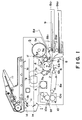
- Figure 1 shows a general arrangement of a copying machine.
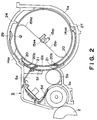
- Figure 2 is a sectional view of a developing apparatus.
- Figure 3 is a perspective view of a toner cartridge.
- Figure 4 is an exploded view of a part of a toner cartridge.
- Figure 5 illustrates a stirring member
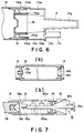
- Figure 6 is a sectional view of a part with a grip.
- Figure 7 illustrates mounting of the stirring member to a toner replenishing container.
- Figure 8 illustrates toner filling
- Figure 9 is a sectional view of a seal between a gear of a stirring member and a flange
- Figure 10 is a perspective view of a toner cartridge and a developing apparatus.
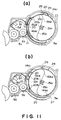
- Figure 11A illustrates a toner cartridge when it is inserted to a cartridge mount.
- Figure 11B illustrates a toner cartridge when it is rotated to an operable position.
- Figure 12 illustrates engagement between a shutter and toner cartridge.
- Figure 13 illustrates mounting process of toner cartridge.
- Figure 14 shows a relation between the toner cartridge and toner cartridge mounting portion.
- Figure 15A illustrates a toner cartridge when it is inserted to a cartridge mount.
- Figure 15B and 15C illustrate a toner cartridge when it is locked at a mounting position.
- Figure 16 shows a positional relation between a toner discharge opening and a flange projection.
- FIG. 17 illustrates another embodiment of the stirring member.
- Figure 18 illustrates a stirring member having a toner passing window in a main blade portion.
- Figure 19 illustrates an embodiment wherein a corner of a toner discharge opening is inclined.
- Figure 20 illustrates an embodiment wherein a toner replenishing container having an integral projection for driving a shutter.
- Figure 21 illustrates an embodiment wherein a toner replenishing container having an integral flange at one end.
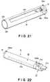
- Figure 22 illustrates an embodiment wherein a grip has an "H" shaped rib.
- Figure 23 illustrates a process cartridge
- Figure 24 illustrates another embodiment of a stirring member in a process cartridge.
- Figure 25 illustrates a stirring member used in an experiment.
- Figure 1 shows an electrophotographic copying machine as an exemplary image forming apparatus using the developer cartridge and developing apparatus according to an embodiment of the present invention
- Figure 2 shows a developing apparatus on which developer cartridge is mounted.
- the image forming apparatus comprises an image reader 1 having an original supporting platen glass 1a, which is illuminated by an illumination lamp 1b.
- the original is scanned by the lamp 1b and scanning mirror 1c.
- the light reflected by the original is projected onto a photosensitive drum 2 through the mirror 1c, reflection mirrors 1d, 1e and 1f, and a focussing lens 1g having a magnification changing function.
- the photosensitive drum 2 has a surface photosensitive layer, and is rotated by a main motor 3 in a direction indicated by an arrow in Figure 1 during image forming operation.
- a charging device 4 Around the photosensitive drum 2, there are a charging device 4, developing device 5, transfer device 6 and cleaning device 7.
- the surface of the rotating photosensitive drum 2 is uniformly charged by the charger 4, and the photosensitive drum 2 is exposed to the light image from the reader 1 so that an electrostatic latent image is formed on the photosensitive drum 2.
- the latent image is developed by the developing device 5 by transferring a developer, which will hereinafter be called “toner”, to the electrostatic latent image.
- the developing device 5 supplies the toner to a developing sleeve 5c containing therein a fixed magnet by a developer blade 5b from a developer chamber 5a.
- the developing sleeve 5c is rotated so that a layer of the toner is formed on the surface of the developing sleeve 5c while triboelectric charge is applied to the toner, by a developer blade 5b.
- the toner is transferred to the photosensitive drum 2 in accordance with the electrostatic latent image, thus visualizing the latent image into a toner image.
- the toner image is transferred onto a recording material 9 fed by a sheet feeder 8 with a transfer voltage applied to the transfer device 6.
- the transfer device 6 has a transfer charger 6a and a separation charger 6b. By application of a voltage of a polarity opposite from that of the toner by the transfer charger 6a, the toner image is transferred onto the recording material 9. After the transfer, a voltage is applied to the recording material 9 by the separation charger 6b to separate the recording material 9 from the photosensitive drum 2.
- the toner remaining on photosensitive drum 2 is removed by a cleaning blade 7a, and the removed toner is collected into a collected toner container 7b, in the cleaning device 7.
- a sheet feeder 8 has a top and bottom cassettes 8a1 and 8a2 at a bottom part of the main assembly of the apparatus.
- the recording material contained in these cassettes are fed out one by one by a pick-up roller 8b1 or 8b2 to a pair of registration rollers 8c.
- a manual feeder 8d there is provided a manual feeder 8d.
- the recording material 9 fed out of the cassette or the manual feeder is fed to the registration rollers 8c, and receives the toner image from the photosensitive drum 2.
- the recording material 9 after the transfer is fed to an image fixing device 10 by a conveyer belt 8, the fixing device comprising a driving roller 10a and a heating and pressing roller 10b containing therein a heater.
- the transferred image is fixed by application of heat and pressure by the fixing device 10.
- the recording material 9 is discharged to the outside of the apparatus by a pair of discharging rollers 8f.
- the copying machine of this embodiment has an automatic document feeder 11 above the original supporting platen 1a, so that originals are automatically fed one by one.
- the document feeder any known types are usable.
- the toner cartridge C As shown in Figure 2 and 3, the toner cartridge C is mountable to a cartridge mount 5e of the developing device 5, and is kept there. It gradually supplies the toner into developer chamber 5a (installing or built-in type).
- the toner cartridge C comprises, as shown in Figure 4, a toner replenishing container 12, a flange 13, a flange 14, a stirring member 15, a cap 16, and a grip 17. Each part will be described in detail. Sealing structure of the stirring member will also described.
- FIG 4 it is generally cylindrical (here, "cylindrical” is not limited to a one having a circular cross-section but covers a polygonal cross-section). It is provided with a toner discharge opening 12a extending in a longitudinal direction thereof and a cut-away portion 12b at each of the opposite longitudinal ends for engagement with a projection of a flange 13 or flange 14 for the purposes of positioning.
- the inner length of the toner replenishing container 12 is preferably approx. 160-400mm, further preferably approx. 180-330mm, even further preferably, approx. 200-310mm.
- the toner supplied into the 5a does not extend throughout the length of the developing sleeve 5c, with the result of tendency of drop-out of toner in a resultant image. If it is larger than 400mm, the length of the developing device 5 is too large to downsize it. The size is determined in accordance with the size of the sheets usable with the apparatus (A3, A4, B4).
- the inner radius of toner replenishing container 12 is preferably approx. 10 - 50 mm, and further preferably approx. 15 - 35 mm, and even further preferably approx. 25 - 30 mm.
- the toner replenishing container 12 has an inner radius of 55mm, a wall thickness of 0.8mm, inner length of the cylinder of 297.5mm.
- the toner discharge opening 12a has a length of 296mm which is generally equal to the length of the toner replenishing container 12, and a width of 7mm.
- the material of the toner replenishing container 12 is preferably thermoplastic resin material, among them ABS resin, polyester resin are preferable because they are easy to manufacture with high dimensional accuracy, because they are relative less expensive and because they are strong against impact, such as falling.
- thermoplastic resin material among them ABS resin, polyester resin are preferable because they are easy to manufacture with high dimensional accuracy, because they are relative less expensive and because they are strong against impact, such as falling.
- HIPS anti-impact polystylene resin
- Beside these materials, paper or aluminum or the like is usable.
- the toner replenishing container 12 As a method of manufacturing the toner replenishing container 12 using thermoplastic resin material, it is preferable to form the toner discharge opening 12a and the cut-away portion 12b by pressing after extrusion. More preferably, inner sizing (cooling core type) is carried out to improve the inner diameter accuracy and circularity. Even further preferably, injection molding is used, since the accuracy is higher than the extrusion. Then, deformation due to hysteresis does not occur even if heat seal of sealing film or hot melt fusing of the flange 13 and flange 14 are effected.
- inner sizing cooling core type
- one of the flanges is integrally molded with the cylindrical portion, as disclosed in Japanese Laid-open Patent Application No. 64803/1993, since then the number of parts and the manufacturing steps can be saved.
- the injection pressure of 500 - 1500 Kgf/cm2, and the filing time of 0.005 - 0.02 sec is preferable.
- the toner discharge opening 12a of the toner replenishing container 12 is sealed by a seal 12cl.
- the seal 12c is removed by an operator upon start of use of the toner cartridge C.
- the seal 12c is in the form of a flexible film of laminations of polyester resin, Nylon, polyethylene resin, ethylenevinylacetate. It has a thickness of approx. 50 - 200 microns, preferably 10 - 150 microns.
- the seal 12c is fixed to the toner replenishing container 12 with such a strength that the toner does not leak during transportation by temperature change, pressure change, vibration, falling, impact or the like and that the peeling is permitted upon use.
- the peeling strength is preferably, not more than 10 kgf at the max., and preferably not more than 6 kgf, further prefly not more than 4.5 kgf, when the seal 12c is folded bach at an angle of 180 degrees and pulled in a longitudinal direction.
- hot plate fusing, impulse sealing, ultrasonic wave fusing, high frequency fusing are preferable, and among them, hot plate fusing is preferable.
- the total length of the seal 12c is not less than twice the length of the toner discharge opening 12a.
- a part thereof not bonded to the toner replenishing container 12 is folded back at 180 degrees to provide a pulling portion, which is lightly fixed by hot melt bonding agent, double sided adhesive tape or the like on a fixed portion of the seal 12c, toner replenishing container 12, flange 13 or grip 17.
- the flange 13 and flange 14 are mounted to the respective ends of the cylindrical portion of the toner replenishing container 12, and they are manufactured through injection molding using ABS resin, polyester resin, HIPS or another thermoplastic resin material.
- the flange 13 and flange 14 each have two projection 13a1 and projection 13a2, projection 14a1 and projection 14a2. The projections are engaged with the cut-away portions 12b of toner replenishing container 12.
- flange 13 is provided with a filling opening 13b for permitting the toner to feed therethrough.
- a cross rib 13c is formed, and a a bore 13d for receiving the stirring member 15 is formed at the center of the cross rib 13c.
- diameter of the filling opening 13b is not less than 50% of the inside diameter of the toner replenishing container 12, further preferably not less than 60% from the standpoint of improving the filling period and filling efficiency.
- flange 14 is provided with a bore 14b for receiving stirring member 15, and around the bore 14b, there is a jaw 14c for supporting an outer periphery of a gear 15a2 of the stirring member 15.
- the jaw 14c is provided with a claw 14d for engagement with a ring rib 15a3 of the gear 15a2.
- Engaging method may be with hot melt bonding, ultrasonic wave fusing, adhesive tape.
- hot melt is preferable because sufficient sealing and bonding strength can be provided without difficulty.
- a method of applying a hot meld bonding material to an inner surface of the toner replenishing container 12 is preferable, since there is no liability of outside projection of the bonding material.
- the stirring member 15 comprises a stirring shaft 15a and a stirring blade 15b.
- the stirring shaft 15a is in the form of a rod having an "H" cross-section, for example, At one longitudinal end thereof, a portion 15a1 to be received by a bore 13d of the flange 13 is formed, and at the other end, the gear 15a2 is formed for connection with a driving system.
- the gear 15a2 has a ring rib 15a3 at the outer periphery. Press-fitting bosses 15a4 are formed for supporting stirring blade 15b.
- the stirring shaft 15a has a sufficient straightness, and therefore, the stirring shaft 15a has a generally "H", “L”, “T” or the like to prevent bending, and particularly "H” is preferable.
- the material of the stirring shaft 15a is preferably polyacetal (POM) in consideration of the sliding property at the bearing portions and the anti-creep.
- POM polyacetal
- injection molding is preferably used from the standpoint of easy manufacturing.
- the stirring blade 15b to be mounted to the stirring shaft 15a is provided with a projection projected at least in two directions from the shaft 15a.
- it comprises a major blade portion 15b1 and auxiliary blade portion 15b2 in two directions.
- the major blade portion 15b1 has an end portion over the entire length of the shaft 15a, and there are provided slits 15b3.
- slits 15b3 In communication with the slits 15b3, there are provided rectangular holes 15b4.
- the auxiliary blade portion 15b2 has an end surface at a position corresponding to the slit 15b3.
- a plurality of press-fitting bores 15b5 are provided to receive the boss 15a4 of the stirring shaft 15a.
- the material for the stirring blade 15b it preferably shows proper elasticity and proper anti-creep for example, polyurethane rubber sheet, or cloth coated with rubber, and particularly preferable material is a polyester (PET) film. It preferably has a thickness of approx. 50 - 500 ⁇ m, further particularly approx. 150 - 300 ⁇ m. If it is smaller than 50 ⁇ m, the elasticity is not enough with the result of lower toner feeding force. If it is larger than 500 ⁇ m, the elasticity is too strong with the result of required large torque to rotate the stirring blade 15b in contact with the inner surface of the container 12. In this embodiment, the thickness is approx. 188 ⁇ m.
- the above-described material is stamped out by pressing, since it is of high accuracy without high cost.
- the stirring shaft and stirring blades 15b thus manufactured are integrated by inserting the boss 15a4 into the bore 15b5, press-fitting them by heat or ultrasonic wave.
- the stirring member 15 is inserted into the container 12, and the opposite ends thereof are supported by the flanges 13 and 14 to permit the rotation thereof.
- the method of mounting the stirring member 15 will be described hereinafter.
- the description will be made as to the shape of the stirring blade 15b.
- the stirring blade 15b projects from the stirring shaft 15a in at least two directions. Particularly, it is preferable as in this embodiment that the blade extending in the two directions has different lengths of tangent line with respect to the internal wall surface of the container 12.
- One of the main blade portion 15b1 is provided with a plurality of slits 15b3 but it is still extended over the entire length of the blade 15a, and therefore has a sufficient restoring force, and therefore, has a high toner feeding power.
- the slits 15b3 and the holes 15b4 are effective to prevent increase of the torque.
- the auxiliary blade portion 15b2 extended only at the portion corresponding to the slit 15b3 and the holes 15b4, are effective to reduce the remaining amount of the toner. By doing so, if the comparison is made with a blade portion extended uniformly in the two directions, the required torque is smaller in this embodiment despite the higher toner feeding force.
- the width of the slit 15b3 in the main portion of the blade 15b1 has a width of approx. 0.5 - 3 mm.
- the interval between the slits is preferably approx. 20 - 60 mm, further preferably approx. 30 - 55 mm, even further preferably approx. 34 - 52 mm.
- the length of the rectangular hole 15b4 in the longitudinal direction is preferably approx. 20 - 80 % of the interval of the slits. It is preferable that the side thereof which is parallel with the stirring shaft 15a and adjacent to the shaft 15a is in contact with the stirring shaft 15a.
- the length of the end surface of the auxiliary portion 15b2 measured along the length of the rotational shaft is preferably approx. 5 - 15 mm longer than the width of the slit 15b3.
- the description will be made as to the distance of the stirring blades 15b1 and 15b2 in the radial direction. It is slightly longer than the internal radius of the container 12a, so that it is rotated with light contact with the inner wall of the container 12a. By doing so, the stirring blades 15b1 and 15b2 are rotated with small deformation, and when the deformation is removed by the elasticities of the blades 15b1 and 15b2 at the opening 12a, the toner is thrown, by which the toner supplying effect is increased.
- the distance from the rotational center of the stirring member 15 to the free end of the blade is longer by approx. 0.5 - 5 mm, preferably 1.0 - 4 mm, further preferably 1.5 - 3 mm approximately than the inner radius of the container 12.
- the difference is smaller than 0.5 mm, the sufficient restoration force of the blade is not expected, and if it is larger than 3 mm, the toner feeding power is too large with the result of excessive toner supplied into the developer chamber 5a, which may lead to caking of the toner. Additionally, the required rotational torque is large.
- the stirring shaft 15a and the stirring blades 15b are separately manufactured, and are integrated by press-fitting.
- the stirring shaft 15a and the stirring blade 15b may be integrally formed through ejection molding or the like.
- a high speed and high pressure injection molder is preferably used since then the thick wall portion of the shaft and the thin wall portion of the blade can be simultaneously molded with high precision.
- the ejection pressure is approx. 500 - 1500 kgf/cm2
- the filling time of the resin material is preferably approx. 0.005 - 0.02 sec.
- the stirring shaft 15a can be a hollow shaft, which is convenient from the standpoint of the straightness of the stirring shaft 15a.
- the cross-section is preferably circular in which two parts are removed in the hollow part. The removed part is effective as a seat for the mounting of the stirring blade 15b.
- the cap 16 functions to plug the filling opening 13b in the flange 13, after the toner is filled in the container 12. It is of low density polyethylene, high density polyethylene, polypropylene or the like (preferably low density polyethylene), and in the form of a cylinder having a bottom portion.
- the grip 17 It is effective to cover the cap 16 for the opening 13b after the filling of the toner into the container 12, and also to function as a grip when mounting or demounting the toner cartridge C, relative to the developing device 5.
- it has an integral movable lever 17c constituting locking means for preventing rotation of the engaging portion 17a, grip 17b and the toner cartridge C.
- PP polypropylene
- ABS acrylonitrile styrenebutadiene copolymer
- HIPS anti-impact polystyrene
- Polypropylene is further preferable since the movable lever 17c using elasticity is provided.
- the engaging portion 17a functions to engage the grip 17 in the flange 13. It is in the form of a cylinder, and at an end thereof, a cut-away portion 17a1 is formed corresponding to the projection 13a1 or 13a2 of the flange 13. At several positions of the internal surface (equidistant three portions in this embodiment), engaging claws 17a2 are provided. By engaging the cut-away portion 17a1 with the projections 13a1 and 13a2, by which the positioning is accomplished. It is firmly locked into a recess 13e in the outer surface of the flange 13, by which the grip 17 is fixed to the flange 13.
- the inside surface of the engaging portion 17a is provided with several ribs 17a3 (four ribs are preferable).
- the internal diameter between end of the ribs is substantially equal to the outer diameter of the cap 16.
- the internal diameter portions of the ribs confined outer peripheral surface of the cap 16.
- a stepped portion 17a4 is formed, at a position for confining an end of the cap 16 when the grip 17 is engaged with the flange 13, as shown in Figure 6.
- the above-described clamping method is not limiting, but hot melt bonding, ultrasonic wave fusing, press-fitting, adhesive tape or the like are usable.
- the above-described clamping method is preferable since it is easy. When this is used, disengageable structure is usable.
- the movable lever 17c is vertically movable by the elasticity of the engaging portion 17a with a slit in the engaging portion 17a. At a predetermined position, a locking projection 17c1 is formed. The projection 17c1 is locked at a predetermined position of the developing device 5 when the toner cartridge C is mounted on the developing device 5 with the rotation, so that the rotation of the toner cartridge C is prevented during image forming operation.
- the sheet 12c is mounted to the opening 12a of the container 12 to plug the opening 12a, and a hot melt bonding material is applied on the internal surface of the container 12 at the opposite end portions.
- the projections 13a1, 13a2, 14a1 and 14a2 of the flanges 13 and 14 are aligned with the cut-away portions 12b of the container 12.
- the flanges 13 and 14 are engaged and bonded at the opposite ends of the toner replenishing container 12.
- a stirring member 15 comprising the stirring shaft 15a and the stirring blades 15b mounted thereon is inserted into the bore 14b of the flange 14 to mount it to the container 12. Since the stirring blades 15b are flexible and thin, and since the length between the end of the main blade portion 15b1 and the auxiliary blade portion 15b2 is larger than the diameter of the bore 14b, the insertion is not easy.
- a tool 18 is mounted to the flange 14.
- the tool has a bore 18a in the form of a funnel having gradually and continuously decreasing diameter.
- the small diameter portion of the funnel bore 18a has the same size as the bore 14b of the flange 14.
- the small diameter portion and the bore 14b are continuous. Therefore, when the stirring member 51 is inserted into the funnel bore 18a of the tool 18, the blades 15b1 and 15b2 are deformed along the surface of the funnel bore 18a, and therefore, they are smoothly inserted into the bore 14b of the flange while being along the bore surface.
- the tool 15 has a diameter permitting insertion into the filling opening 13b of the flange 13, and is provided with a cross groove (not shown) to avoid interference with the cloth rib 13c of the filling opening 13b.
- An end of the tool 19 is provided with a hole 19a, and has a larger diameter at the end. The diameter gradually decreases, and the smallest diameter portion is continuous with the hole 13d. Therefore, the engaging portion 15a1 of the end of the stirring member inserted from the flange 14 of the container 12 is guided by the funnel bore 19a and is smoothly brought into engagement with the shaft bore 13d.
- the stirring member 15 is pushed strongly, by which the wing rib 15a3 of the gear 15a2 ( Figure 4) is engaged with the claw 14d of the flange 14 and clamping therebetween is established to prevent movement along the shaft is prevented.
- the outer periphery of the gear 15a2 is supported on the ring jaw 14c ( Figure 4) of the flange 14 to prevent movement in the radial direction. Therefore, the stirring member 15 is supported by the flanges 13 and 14 without play.
- a sealing member for preventing toner leakage is preferably mounted between them to prevent leakage of the toner between the bore 14b of the flange 14 and the gear portion 15a2 of the stirring member 15.
- the toner is filled through the opening 13b.
- the toner (one component magnetic toner in this embodiment) T is filled using developer hopper 30.
- the developer hopper 30 is provided with a supply port 30b for permitting supply of the toner T, at an upper portion of the funnel like main body 30a.
- an adopter 30c for fitting with the port 13b of the toner cartridge C is mounted.
- Inside the main body 30a there is an auger 30d which is rotatable. By properly controlling the rotation of the auger 30d, the toner filling speed can be controlled.
- the inside surface of the main body 30a is treated with fluorine to reduce the frictional coefficient, by which the toner filling efficiency from the developer hopper 30 to the toner cartridge C is improved.
- a gap 16 is press-fitted to the opening 13b, thus plugging the opening 13b.
- the projections 13a1 and 13a2 of the flange 13 are aligned with the cut-away portion 17a1 of the grip 17, and the engaging portion 17a of the grip 17 is press-fitted into the flange 13, by which an engaging claw 17a2 of the engaging portion 17 is locked in a locking recess 13e of the flange 13 so that they are securedly clamped.
- the cap 16 is completely hidden, and the cap 16 is fixed by the rib 17a3 ( Figure 6).
- the material for the gasket 30 it is preferably elastic, and foamed polyetylene resin or polyurethane or the like, rubber sponge or wool felt or the like are usable.
- the wool felt is particularly preferable because it has a proper elasticity, and is excellent in the durability with relatively good sliding property so that the required torque of the stirring member 15 can be lowered. In addition, it is less expensive. Therefore, in this embodiment, a wool felt having a thickness of 3.0 mm and an apparent density of 0.28 g/cm3 is used. It is compressed to 2.5 mm between the gear 15a2 and the flange 14.
- the compression ratio is determined on the basis of the dimensions of the stirring member and the flange 14 and the thickness of the gasket 30. It is easy to increase or decrease the compression ratio.
- the stirring member 15 and the flange 14 are manufactured by injection molding of the thermoplastic resin material, and therefore, there is a possibility that fine pits and projections are formed on the contact surface to the gasket 30. For this reason, if the density of the gasket 30 is too high, it becomes difficult to assure the sealing property by accommodating the pits and projections.
- the density of the gasket 30 is too low, it is difficult to maintain the sealing property for a long period of time, and in addition, in the case of the wool felt, it becomes easily fuzzy. Therefore, if the density of the gasket 30 is too low, the dimensional variation and the surface roughness can be easily accommodated, and therefore, the sealing property can be easily accomplished. However, when the compressed state lasts for a long term, a permanent compression deformation results, and therefore, the sealing property is rather insufficient.
- the gasket 30 is preferably wool felt, and preferably has an apparent density of 0.20 g - 0.35 g/cm3, further preferably 0.25 - 0.30 g/cm3.
- the compression ratio of the gasket 30 is property determined in accordance with the material of the gasket 30 and the apparent density. In the case of the wool felt having the above-described apparent density, it is preferably 4 - 40 %, further preferably 10 - 30 % and even further preferably 15 - 20 %. If the compression ratio is smaller than the range, the permanent deformation results from the long term compression so that the sealing property is lowered. If it is larger than the range on the contrary, the sealing property is lowered, and the required torque increases.
- the flange 14 is provided with a ring rib 14e to which an inside diameter portion of the gasket 30 in the form of a flat ring is contacted.
- the rib 14e is provided for the following purposes.
- the rib 14e sandwiches the gasket 30 to prevent the gasket 30 from being rotated by the stirring member 15, and in addition, it is effective to prevent the fibers of the wool felt from entering the toner replenishing container 12.
- the stirring blade 15b is inserted into the container 12
- the gasket 30 is prevented from becoming fuzzy, and in addition, it is effective to guide the stirring blade 15 into the hole 14b.
- the gear 15a2 is abutted to the rib 14e so that the stirring member 15 is prevented from entering the container 12, thus preventing release of the engaging portions.
- a space 31 is formed between the rib 14e and the gear 15a2, and the space functions as a buffer for the toner particles stirred in the container 12. That is, when the toner particles receive shearing force, they escape to the space so that the shearing force is eased, thus preventing production of caked particles (coarse particles).
- the engaging portion between the flange 14 and the gear 15a2 (claw 14d and the ring rib 15a3) are outside of the gasket 30, and therefore, the leaked toner is prevented from reaching the engaging portions. Therefore, the production of coarse particles as a result of agglomeration by the friction between the engaging portion, can be prevented. Thus, white stripes and black dots resulting from the coarse particles, can be prevented beforehand.
- An interval L1 between the hole 14b and the stirring member 15 is 0.3 - 3 mm, preferably 0.3 - 1.5 mm, and further preferably about 0.5 mm such that the stirring rod 15 is not contacted to the inside of the hole even if it is eccentric, and such that the hole diameter is minimized.
- the engaging length L2 of the claw 14d is preferably 0.3 - 3 mm, further preferably 0.7 - 2 mm and even further preferably 1.2 mm such that the engaging is assured while the engagement is easy.
- the gap L3 between the end of the rib 14e and the gear 15a2 is preferably 0.3 - 1 mm, further preferably 0.3 - 0.7 mm, and even further preferably about 0.5 mm such that the fibers of the gasket is prevented from entering the container 12 and that the gear 15a2 is not rubbed with the rib 14e.
- the thickness L4 of the compressed gasket 30 is preferably 1 - 5 mm, further preferably 2 - 3 mm and even further preferably 2.5 mm such that the sufficient sealing property is provided and such that the coarse toner particles are not produced.
- the above-described dimensions are easily accomplished by properly selecting the dimension of the gasket 30 and the flange and the stirring member 15.
- the gear 15a2 is integrally formed on the stirring shaft 15a of the stirring member 15, and therefore, the selection of the above-described dimensions is easy. As compared with the case of using separate members, the numbers of parts and manufacturing steps and be reduced.
- the toner cartridge C is inserted into a cartridge mount 5e of the developing apparatus 5, as shown in Figure 10.
- the developing device 5, as shown in Figure 2 is provided with a cartridge mount 5e for receiving the toner cartridge C adjacent the developer chamber 5a.
- the mount 5e and the developer chamber 5a are in communication with each other through an opening 5f.
- the communicating portion is provided with a shutter 20 for closing and shutting the opening 5f.
- the shutter 20 rotates with mounting and demounting of the toner cartridge C.
- the shutter member 20 closes the opening 5f to permit reverse flow of the toner from the developer chamber 5a to the mount 5e.
- the shutter 20 is confined by a spring 29 mounted to the inner top surface of the cartridge mount 5e, so that it is not removed. With this state, the shutter member 20 is sandwiched between projections 14a1 and 14a2.
- the shutter 20 When the toner cartridge C is rotated from the mounting and demounting position to the using position, the shutter 20 is urged by a projection 14a1 and therefore is rotated to open the opening 5f, as shown in Figure 11B, to permit toner supply from the toner cartridge C into the developer chamber 5a.
- Figure 12 shows a relation between the toner cartridge C and the shutter 20.
- the shutter 20, as shown in Figure 12, is provided with an opening 20a in a semi-cylindrical surface along the peripheral of the container 12.
- the configuration and size of the opening 20a are generally the same as the opening 12a of the container 12, or the opening 20a of the shutter member 20 is slightly larger.
- the shutter member 20 is an SUS or the like plate stamped out and bent.
- a sealing member 20b is mounted around the internal surface of the opening 20a to prevent the toner leakage (Figure 11).
- the sealing member 20b is preferably elastic material such as polyester, polyurethane foamed material or the like.
- the seal 20b is contacted to the outer surface of the toner cartridge C to prevent the leakage of the toner between the shutter 20 and the toner cartridge C.
- the similar seal 21 is provided between the periphery of the opening 5f of the developer chamber 5a and the shutter 20, thus preventing the toner leakage therebetween.
- two grooves 23a and 23c are formed at positions corresponding to the projections 14a1 and 14a2 of the flange 14, as shown in Figures 14a and 13b, and therefore, the insertion of the toner cartridge C is prevented unless they are aligned.
- the flange 13 is provided with projections 13a1 and 13a2. However, the angular positions thereof are aligned with the projections 14a1 and 14a2, and the corresponding projections 13a1 and 13a2 are of the same configurations, or the projections 13a1 and 13a2 a smaller, and therefore, the flange projections 13a1 and 13a2 are automatically insertable into the grooves 23a and 23b.
- the flange projections 14a1 and 14a2 have different sizes, and they are not diametrically opposite, and therefore, the insertion angle of the toner cartridge C is limited to one.
- the opening 12a is controlled to face upward, by which the toner scattering upon the mounting or demounting of the toner cartridge C.
- the small amount of the toner remaining therein may scatter, but this is effectively prevented.
- the inside surface of the cartridge mount 5e is provided with a guiding rail 24 parallel with the inserting direction of the cartridge, along which the flange projection 14a1 is guided. Therefore, when the operator does not insert the toner cartridge C to a predetermined position, the rotation of the toner cartridge C in the mounting direction (arrow in Figure 14B) is not permitted.
- a jaw 25 is formed at an insertion end of the cartridge of the cartridge mount 5e, as shown in Figure 14A.
- the lever 17c deforms by elasticity, by which a locking projection 17c1 goes beyond the jaw 25.
- the locking projection 17c1 is engaged with the jaw 25, and therefore, the toner cartridge C is prevented from removed from the cartridge mount 5e together with the sealing member 12c.
- the opening 12a and the shutter opening 20a are in communication with each other as shown in Figure 12, and the flange projections 13a1, 13a2, 14a1 and 14a2 are engaged with the end portions of the shutter member 20 with the four corners of the shutter 20 being sandwiched thereby.
- the shutter member is integrally rotatable with the rotation of the toner cartridge C.
- the sealing member 12c of the opening 12a is peeled off.
- the toner cartridge C is completely accommodated by the cartridge 5e, the toner scattering or leaking can be prevented.
- the toner cartridge is shaked or rolled conventionally. In such a case wherein the toner powder in the container 12 contain sufficient quantity of air so that the apparent density of the toner is low, and the flowability of the toner is high, the toner scattering effect is remarkably advantageous.
- the operator then rotates the toner cartridge C to direct the toner discharging opening 12a in a predetermined direction.
- the opening 5f of the developing device 5 is at a lateral portion of the toner cartridge C, and therefore, the opening 12a is directed substantially horizontally. Since the shutter 20 is sandwiched by the flange projections 13a1, 13a2, 14a1 and 14a2 of the toner cartridge C, as described above, when the toner cartridge C is rotated with the grip 17b, the shutter 20 is integrally rotated. At this time, the close contact is maintained between the outer peripheral surface of the toner cartridge C and the shutter member 20 and between the developer chamber 5a and the shutter 20, by the sealing members 20b and 21.
- the description will be made as to the relationship between the flange projection of the toner cartridge and the toner discharging opening 12a in this embodiment. If the flange projection is at any position away from a longitudinal extension of the toner discharging opening 12a, the rotation of the shutter 20 is permitted irrespective of whether it is provided on only one of the flanges 13 and 14. However, at least one flange projection is provided at each longitudinal end of the toner cartridge C since then the force relating to the opening or closing of the shutter 20 is distributed uniformly to the opposite ends of the shutter member 20 and the toner cartridge C, by which deformation of the toner cartridge C is prevented to permit smooth opening or closing motion of the shutter 20.
- projections 13a1 and 14a1 for moving the shutter 20 to open the opening 5f by engagement of the side surface with the shutter 20, and projections 13a2 and 14a2 for moving the shutter 20 to close the opening 5f, are separate portions from each other, and therefore, the load applied to the projection can be reduced.
- two projections 13a1, 13a2, 14a1 and 14a2 for the opening and closing functions, respectively, are disposed at opposite positions with an extension of the opening 12a therebetween, at the longitudinal ends of the cartridge C. This is preferable.
- the shutter 20 is sandwiched by the opening projections 13a1 and 14a1 and the closing projections 13a2 and 14a2.
- the projections 13a1, 13a2, 14a1 and 14a2 may be fused or bonded on the toner replenishing container 12, or they may be integrally molded with the container 12. However, from the standpoint of the strength and the cost, they are preferably integrally molded on the flanges 13 and 14.
- the ends, adjacent to the toner discharging opening 12a, of the flange projections 13a1, 13a2, 14a1 and 14a2, are engaged with the shutter 20 so that they receives the largest force upon the shutter opening and closing. For this reason, the component in the direction away from the center of the cylinder of the container 12 and the component toward the center, are as small as possible. Therefore, the ends, adjacent to the toner discharging opening 12a, of the flange projections 13a1, 13a2, 14a1 and 14a2, are substantially perpendicular to the outer peripheral tangent line of the cylinder at the portion.
- the heights of the projections 13a1, 13a2, 14a1 and 14a2 are preferably such that it is projected beyond the outer surface of the container 12 by approx. 2 - 10 mm to ensure the engagement with the shutter 20 and to permit opening and closing motion of the shutter 20.
- the projection is further preferably 4 - 6 mm. If it is smaller than 2 mm, the degree of engagement is too small with the possible result that the engaging portion of the shutter 20 rides on the projections 13a1, 13a2, 14a1 and 14a2 upon the opening or closing of the shutter 20. If it is larger than 10 mm, the cartridge mount 5e becomes bulky.
- an angle formed between a line connecting the center of the cylinder of the container 12 and the center C1 in the longitudinal direction of the toner discharging opening 12a and a line connecting the center of the cylinder and an end of the projections 13a1 and 14a1 adjacent to the toner discharging opening is ⁇ 1
- an angle formed between a line connecting the center of the cylinder and the longitudinal center C1 of the toner discharging opening 12a and the ends of the projections 13a2 and 14a2 adjacent to the toner discharging opening and the center of the cylinder is ⁇ 2.
- the angle ⁇ 1 is preferably approx. 20 - 90 degrees, further preferably approx. 30 - 50 degrees, even further preferably approx. 40 - 50 degrees.
- the angle ⁇ 2 is preferably approx. 70 - 160 degrees, further preferably 105 - 130 degrees, even further preferably approx. 110 - 120 degrees.
- the angle ⁇ 1 is 45 ⁇ 1 degrees, and ⁇ 2 is 115 ⁇ 1 degrees.
- the angle ⁇ 1 is smaller than 20 degrees and ⁇ 2 is smaller than 70 degrees, the projections 13a1, 13a2, 14a1 and 14a2 are close to the opening 12a of the less rigid toner container 12, and therefore, the toner discharge opening 12a is easily deformed during the opening and closing operation of the shutter. In addition, the space for the seal 20b is limited. If the angle ⁇ 1 is larger than 90 degrees, or ⁇ 2 is larger than 160 degrees, the circumferential length of the shutter 20 becomes long with the result of larger operational force required for the opening and closing of the shutter 20.
- shutter opening projections 13a1 and 14a1 and shutter closing projections 13a2 and 14a2 are provided at the longitudinally opposite ends of the toner replenishing container 12. If the projection is provided only one longitudinal end of the container 12, the positions of the projections faced to each other with the toner discharging opening 12a therebetween are such that the line connecting the center of the cylinder and the longitudinal center of the opening 12a and the line connecting the center of the cylinder and the projection side end adjacent the toner discharging opening 12a forms an angle between approx. 20 - 160 degrees, for the reasons described in the foregoing.
- an inclined surface 17c2 is formed. Therefore, even if the lever 17c is not pressed, when the cartridge C is rotated in the mounting direction, the locking projection 17c1 is abutted to the end 25a of the jaw, and the lever 17c elastically deforms along the inclined surface 17c2, so that the locking projection 17c1 goes beyond the end 25a. After this, the movable lever 17c elastically deforms with the result of automatically locking. By this click, the operator can sense the assured mounting of the toner cartridge C.
- the toner cartridge C is mounted to the developing device 5 to permit image forming operation.
- the description will be made as to the toner feeding from the toner cartridge C during the image forming operation.
- the driving force is transmitted to the stirring member 15, and the member 15 rotates in the clockwise direction in Figure 11B at 10.2 rpm, for example.
- the toner in the toner replenishing container 12 is sufficiently stirred and uniformed by the stirring blade 15b, and in addition, it is properly electrically charged.
- the toner is fed to the developer chamber 5a of the developing device 5 through the toner discharge opening 12a, the shutter opening 20a and the opening 5f of the developing device.
- the toner discharge opening 12a is directed substantially horizontally, and therefore, a large amount of unstirred or uncharged toner is prevented from being supplied into the developing device 5 at once.
- the toner feeding force by the stirring member 15 is sufficiently strong, and therefore, the amount of the toner in the developer chamber 5a is maintained at a constant level.
- the stirring blades 15b are of elastic material, and the rotational radius thereof is slightly longer than the radius of the cylinder of the toner container so that the ends thereof are slightly extended out of the toner discharging opening 12a. More particularly, the blade 15b is slightly deformed with the friction with the internal wall surface of the container 12, but at the toner discharging opening 12a, it is elastically restored to throw the toner into the developing device 5.
- the elastic throwing of the toner is not strong when the amount of the toner in the container 12 is large because the existence of the large amount of the toner functions as resistance, and therefore, toner agglomeration as a result of excessive amount of the toner in the developing device 5 and the improper image formation attributable to the agglomeration, can be prevented.
- the stirring rod 15b is deformed, the increase of the required torque is prevented.
- the restoring action of the blade 15b becomes smooth, so that higher toner feeding power is provided.
- the stirring blade 15b is rotated while being in sliding contact with the internal wall of the toner replenishing container 12, it would be considered that the toner cartridge C is rotated by the rotation of the stirring member 15.
- the locking projection 17c1 is abutted to the jaw 25 of the cartridge mount 5e ( Figure 15B and Figure 15C), the toner cartridge C is not rotated thereby, thus maintaining the position of the toner discharge opening 12a (particularly the angular position at the bottom edge) in a stabilized manner, thus stabilizing the toner supply amount and the image quality.
- the bottom edge of the toner discharge opening 12a is within ⁇ 10 degrees, further preferably ⁇ 5 degrees, when the horizontal direction of the center of the cylinder of the container 12 is 0 degree, when the cartridge C is mounted.
- the angle is -3.6 degrees.
- the operator When the cartridge C is demounted from the developing device 5, the operator lowers the lever 17c of the grip 17 toward the gripping portion 17b from the position of use shown in Figure 15b and 15c to release the engagement between the locking projection 17c1 and the end 25a of the jaw 25.
- the cartridge C is then rotated in the clockwise direction toward the mounting and demounting position (pose), thus returning the opening 12a to the top.
- the toner cartridge C is pulled out of the cartridge mount 5e.
- the toner cartridge C is not pulled out unless it is rotated to the extent that the opening 12a is directed upward, conversely to the case of the toner cartridge C mounting.
- the rotational direction of the toner cartridge C from the mounting and demounting position to the use position is opposite from that of the toner cartridge C from the use position to the mounting and demounting position.
- the projections 13a2 and 14a2 are moved to a position for the shutter member to close the opening 5f.
- the outer surface of the toner replenishing container 12a and the shutter 20 are closely contacted so that the sealing is maintained. Therefore, the toner is not deposited on the outer peripheral surface of the toner cartridge C used up, when it is removed from the developing device 5, and therefore, the operator's hands or wearings are not contaminated with the toner. Therefore, it is easy to dispose of the toner cartridge C used up.
- the toner feeding force of the stirring member 15 is high so that the remaining amount of the toner in the used-up cartridge C is very small, and therefore, the toner scattering or the like can be prevented while the used-up toner cartridge C is disposed of.
- the toner cartridge C used in this embodiment is operated for the image formation in the manner described above. After the toner is used up, it is reusable through a recycling process which will be described hereinafter.
- the stirring member, the toner replenishing container, the grip, and the recycling process will be described in this order.
- the main blade portion 15b1 and the auxiliary blade portion 15b2 are bent toward downstream with respect to the rotational direction of the stirring member 15. In this case, the end portion of the blade approaches obliquely to the toner, and therefore, the required torque of the stirring member 19 is reduced.
- the configuration of the stirring blade 15b is effective. If the blade 15b is bent in this manner, the contact angle between the end of the stirring blade and the internal wall of the toner supply chamber is relatively small as compared with the first embodiment, and the coarse particle occurrence of the toner is reduced.
- the bending angle is preferably approx. 0 - 90 degrees, preferably approx. 20 - 90 degrees, even further preferably 40 - 90 degrees, from the standpoint of reduction of the required torque and increase of the toner feeding force.
- the bent portion of the blade is positioned at approx. 50 - 95 %, further preferably approx. 60 - 90 % and even further preferably approx. 70 - 80 % of the total length of the blade away from the rotational axis.
- the stirring blade 15b may be constructed as shown in Figure 18.
- a plurality of toner passing windows 15b6 are formed between the holes 15b4 of the main blade 15b1. By doing so, the toner passes not only through the holes 15b4 but also through the windows 15b6 when the stirring member 15 rotates during image forming operation so that the torque required by the stirring member 15 can be reduced.
- the rigidity of the main blade portion 15b1 can be adjusted so that the toner can be thrown through the discharge opening 12a with proper strength.
- the toner discharge opening 12a is rectangular ( Figure 4).
- the corner of the rectangular shape adjacent the grip 17 (the bottom corner when the cartridge C is mounted to the developing device 5, in this embodiment) 12a1 is tapered to provide narrower portion than the opening portion.
- the shutter 20 is integrally rotated with the cartridge C when the toner cartridge C is mounted or demounted.
- the flanges 13 and 14 are provided with projections 13a1 and 13a2, and 14a1 and 14a2, respectively, for engagement with an end of the shutter 20.
- the projections 13a1 and 13a2, and 14a1 and 14a2 may be provided at a longitudinal end of the container 12, as shown in Figure 20, rather than the flanges 13 and 14.
- At least one of the flanges 14 and 14 and the container 12 may be integrally formed.
- the flange having the filling opening 13b is integrally formed since then tilting or metal core can be prevented.
- the molder in this case, ultra-high speed and high pressure injection molder is preferably used, and the ejection pressure is 500 - 1500 kgf/cm2, and the filling time of the resin is 0.005 - 0.02 sec approximately, as a preferable levels,
- the projections 13a1, 13a2, 14a1 and 14a2 are required to have a predetermined angular relationship with the toner discharge opening 12 formed in the toner replenishing container 12 ( Figure 17), and therefore, when the toner container 12 is injection molded, the above-described integral forming is effective to make the positioning more accurate without difficulty.
- the grip 17 may be constructed as shown in Figure 22.
- the grip 17 is provided with a rib 17d in the form of "H" at a position opposite from the side having the toner discharge opening 12a when it is mounted to the predetermined position of the engaging portion 17a, that is, the toner container 12.
- the grip 17 and cap 16 are removed, and the toner is refilled through a toner filling opening 13b in the first embodiment described above. It is a possible alternative that the toner is refilled through the toner discharge opening 12a without removing the grip 17 or cap 16.
- the recycling process is as follows.
- the photosensitive drum 2 and/or the developing device 5 or the like constituting the image forming station are provided in the main assembly of the apparatus, and the toner cartridge C for replenishing the toner is detachably mountable.
- the sealing structure ( Figure 10) for preventing the toner leakage between the bore 14b of the flange 14 of the toner cartridge C and the gear 15a2 which is a drive transmitting portion for the starting member 15, is similarly applicable to a process cartridge.
- the process cartridge contains as a unit a photosensitive drum, a charging device, a developing device and a cleaning device, for example.
- a photosensitive drum 32 having a photosensitive layer is rotated, and the surface thereof is uniformly charged by voltage application by a charging roller 33 (charging device).
- the photosensitive drum 32 is exposed to image light from image reader through an exposure station 34 so that a latent image is formed.
- the latent image is in turn developed by developing device 35.
- the developing device 35 feeds the toner by the stirring member 35b, and a developing sleeve 35d containing therein a stationary magnet 35c is rotated.
- a layer of toner having triboelectric charge is formed on the surface of the developing sleeve 35d.
- the toner is transferred onto the photosensitive drum 32 in accordance with the latent image, by which a toner image is formed as a visualized image.
- a transfer device in the main assembly is supplied with a voltage having a polarity opposite from that of the toner, so that the toner image is transferred onto a recording material 9.
- the residual toner remaining on the photosensitive drum 32 is scraped off by a cleaning blade 36b, and is received by a receiving sheet 36b.
- the received toner is collected in a residual toner container 36c. In this manner, the residual toner is removed from the photosensitive drum 32.
- Bias parts such as the photosensitive drum 32 is contained in a housing connected with the toner container 37a, the developing frame 37b and cleaning container 37c, thus constituting a cartridge.
- the cartridge is detachably mountable to a cartridge mount in the main assembly of the image forming apparatus.
- the process cartridge B contains the toner replenishing container 35a and the photosensitive drum 32 or the like, as well, and therefore, the toner replenishment is facilitated, and in addition, the maintenance of the photosensitive drum 32 or the like is also facilitated.
- the stirring member 35b has an integral coupling gear 35b3 at an end of the stirring shaft 35b1.
- the stirring shaft 35b1 is provided with stirring blade 35b2 which is similar to that in the first embodiment.
- This is rotatably supported on the toner replenishing container 35a to feed the toner out of the container through a toner discharge opening 35a1.
- the sealing structure between the gear 35b3 of the stirring member 35b and the container 35a is made same as that described in conjunction with Figure 10 in the first embodiment, by which the similar effect as in the first embodiment can be provided.
- a flat ring gasket is compressed as a sealing member (wool felt compressed at compression ratio 4 - 40 %, for example).
- the engaging portion between the gear 35b3 and the toner container 35a (for example, the engaging portion of a claw of the container 35a and a portion for engagement therewith in the gear 35b3) is outside the toner container beyond the gasket, by which the toner does not leak to the engaging portion during the image forming operation, and the production of coarse toner particles can be prevented beforehand.
- the stirring member may be constructed as shown in Figure 24A, as well as being constructed with a flexible member. That is, the stirring member 38 comprises a rod member 38a bent to stir the toner, and a gear 38b as a drive transmitting member, as a separate member from each other.
- the rod member 38 is inserted through a toner discharge opening 35a1, and another end is inserted into a recess 35a2 of the container 35a.
- the gear 38b is inserted through the bore 35a3 in the container 35, and is mounted to the other end of the rod 38a.
- the stirring member 38 is rotatably mounted to the container 35a.
- a flat ring wool felt gasket 39 is interposed as a sealing member with a compression ratio of 4 - 40 %.
- the engaging portion between the gear 38b and the toner replenishing container 35 is provided with a locking claw 35a5 at an end of the jaw 35a4 in the form of a ring mounted on the toner container 35a.
- the toner in the container 35 is prevented from leaking to the engaging portion during the image formation, and the production of the coarse toner particles can be prevented beforehand.
- the gasket 39 functions to feel two surfaces of the gear 38b, and therefore, the sealing property is high, thus assuredly preventing the toner leakage.
- the process cartridge described above comprises an electrophotographic photosensitive member or the like as the image bearing member, and at least one process means. Therefore, the process cartridge may include, an image bearing member and charging means; image bearing member and developing means; an image bearing member and cleaning means; an image bearing member and two or more of the process means.
- the process cartridge may contain charging means, developing means or cleaning means together with an electrophotographic photosensitive member. It may contain at least one of charging means, developing means and cleaning means and an electrophotographic photosensitive member. As another example, at least the developing means and the electrophotographic photosensitive member may be contained in the cartridge.
- the cartridge thus constituted is detachably mountable to the main assembly of the image forming apparatus.
- known two component magnetic brush development, cascade development, touch-down development, cloud development or the like are usable.
- the image bearing member on which toner image is formed by the developing device 5 is not limited to the photosensitive drum of the first embodiment.
- it may be a photoconductor such as amorphous silicon, amorphous selenium, zinc oxide, titanium oxide or organic photoconductor (OPC) or the like.
- the configuration of the photosensitive member may be a drum, belt or sheet. Usually, drum or belt are widely used. In the case of drum type, it comprises an aluminum cylinder of aluminum alloy or the like and photoconductor evaporated or applied thereon.
- a so-called charging method is used in the first embodiment, but another charging system is usable in which a tungsten wire is shielded with metal such aluminum at three side therearound, and the tungsten wire is supplied with a high voltage, and the positive or negative ions produced thereby are moved toward the surface of the photosensitive drum to uniformly charge the surface of the drum.
- blade type charging blade
- pad type block type
- rod type wire type or the like
- a blade, a fur brush, a magnetic brush or the like are usable.
- the exemplary image forming apparatus using the developing device 5 has been a copying machine.
- the present invention is applicable to another machine if toner is used to form an image, and more particularly it may be a laser beam printer, LED printer, facsimile machine or the like.
- a stirring member 15 of Figure 5 is set in a toner replenishing container 12 of a cylindrical shape having an internal length of 322.5 mm and 55 mm. This is set in a developing device 5 of Figure 2 after being filled with 380 g of one component toner, and the image forming test was carried out.
- the rotational speed of the stirring member 15 was 10.2 rpm.
- a 5.24 % original of A4 size was used and image forming operations were continued in an intermitted durability test mode, while the amount of the toner in the developer chamber 5a and the toner amount in the container 12 were measured.
- the toner amount in the developing device from the space in the developer chamber 5a, approx. 100 g is proper amount.
- the developer chamber 5a is empty, and therefore, a great amount of the toner is supplied into the developer chamber 5a from the container 12, and therefore, the toner amount in the developer chamber 5a relatively quickly increases, but when 100 g is reached, the amount saturates and maintains at a constant level.
- the toner amount in the container 12 decreases, but the amount of the toner in the developer chamber 5a is maintained at approx. 100 g.
- the toner amount detecting means in the developer chamber is set to operate when the amount of the toner in the developer chamber becomes 70 g or less, and when the 70 g is reached, a display requesting the exchange of the container 12 is produced. Until this point, approx. 7000 sheets are subjected to the image forming operations.
- 70 g is sufficient to produce good image even if the original is a solid black image original. Even if new toner is supplied by the exchange with the fresh toner cartridge C, no reverse charge fog is not produced due to self contamination.
- the remaining amount of the toner of the container 12 after the completion of the image forming operations has turned out to be as low as 3 - 5 g.
- the toner amount detecting means is operated when approx. 1500 sheets are processed. At this time, the remaining amount of the toner in the container 12 was 5 - 10 g.
- the relation between the toner remaining amount and the contamination is such that it is dependent on the configuration of the container 12, particularly the size of the toner discharge opening 12a.
- the opening 12a is as small as 7 mm, the toner hardly leaks or scatters during the disposal operation if the remaining amount is less than about 10 g.
- Experiment-2 380 g toner is filled in a toner container 12 having the same structure as in Experiment-1.
- the stirring member 15 is continuously rotated for 10 hours at a speed of 10.2 rpm without opening the toner discharge opening 12a.
- the continuous rotation for 10 hours correspond to 7000 sheets processing. At this time, the required torque is measured. It decreases at an initial stage, and the constant level is maintained thereafter without increase.
- the toner is taken out of the container 12, and filtered with 150 mesh (100 ⁇ m), and it has been confirmed that no coarse toner remains on the filter.
- the weight average particle size of the toner was 7.6 ⁇ m.
- the stirring member 50 comprises a rotational shaft 51, a toner feeding blade 53 and an elastic supporting member 52 therebetween. A slid 54 extending in the radial direction is formed.
- the rotational radius of the toner feeding blade 53 has the same radius as the internal radius of the cylinder 55.
- the toner amount detecting means operated after 6300 sheets are processed, and remaining amount of the toner in the toner replenishing container was 10 - 20 g.
- the used-up cartridge is collected back, and the grip and cap are removed from the cartridge, and the toner discharge opening is shielded. Thereafter, the toner is supplied, and the cap and the grip are mounted.
- the toner cartridge can be reused.
- the stirring member or the like can be reused, thus accomplishing resource saving and energy saving.
- the toner may be supplied through the toner discharge opening in the toner replenishing container without removing the grip or the cap, by which the toner cartridge can be recycled more easily.
- the toner replenishing container is cleaned, or the torque required for rotating the stirring member is checked, so that the toner cartridge having the same performance as a fresh cartridge can be remanufactured.
Abstract
Description
- The present invention relates to a developer cartridge for supplying a developer to a developing apparatus for an image forming apparatus such as a copying machine or printer and a method for remanufacturing method therefor.
- In an image forming apparatus such as an electrophotographic copying machine or a laser beam printer, a photosensitive drum uniformly charged is exposed to a selective light to form a latent image thereon, and the latent image is developed with a developer into a visualized image, and the visualized image is transferred onto a transfer material. In such an apparatus, the developer is required to be supplied each time it is used up. A toner cartridge for supplying the developer into the developing apparatus is classified into a so-called replenishing type wherein all the developer therein is once supplied into a developer receptor in the main assembly of the image forming apparatus, and a so-called installation type wherein the cartridge is installed in the image forming apparatus after it is mounted therein, and the developer therein is supplied out gradually into the developing apparatus until the developer therein is used up.
- Because of the recent demand for downsizing of the apparatus, the installing type cartridge is preferred. Particularly, a type becomes widely used wherein the cartridge is in the form of cylinder having a developer supplying longitudinal opening in the form of a slit, and the cartridge is rotated to direct the opening horizontally rather than downwardly, and the developer is scooped up, as disclosed in Japanese Laid-open Patent Applications Nos. 86382/1987, 170987/1987 and Japanese Laid-open Utility Model Applications Nos. 62857/1988 and 188665/1988, for example.
- The reason for using such an arrangement is that the latitudes of the toner cartridge location and the developing apparatus location are increased from the standpoint of downsizing and from the standpoint of supplying required and sufficient amount of the developer into the developing apparatus to maintain a constant amount of the developer in the developing apparatus, and from the standpoint of maintaining the constant toner/carrier ratio in the case of using two component developer.
- In such an image forming apparatus, a crank-shaped stainless steel is used to stir and feed the toner in the toner cartridge, or a stirring blades as shown in Figure 17 is rotatably mounted in the toner cartridge to feed out the toner, as disclosed in Japanese Laid-open Patent Application No. 131881/1991.
- In the conventional toner cartridge, a grip for mounting and demounting the toner cartridge relative to a developing apparatus is mounted at a front part, in a longitudinal direction, of a cylinder. Therefore, the grip is in the form of a cylinder with the result that the operator has to use the entire hand, not only some fingers. In the limited space in the main assembly of the apparatus, the operator's hand may be contacted to a part in the main assembly. Therefore, the operativity is not so good.
- If the grip is changed to plate like form from the cylindrical shape in an attempt to improve the operativity in the mounting and demounting operations, the filling opening for the developer becomes very small because of the permitted space, and the filling efficiency and the filling rate are decreased.
- A filling opening in a front flange is capped with a cap for closing the filling opening after the filling. The cap is exposed, and therefore, it is easily removed without intention by erroneous handling by the operator or during transportation.
-
- Accordingly, it is a principal object of the present invention to provide a developer cartridge having an improved operativity upon mounting and demounting thereof.
- It is another object of the present invention to provide a developer cartridge wherein a cap for the filling opening is not easily removed.
- It is a further object of the present invention to provide a remanufacturing method for a developer cartridge by which parts can be efficiently used.
- According to an aspect of the present invention, there is provided a developer cartridge, comprising: a cylindrical portion for accommodating a developer, said cylindrical portion being provided with a hole at a longitudinal end; a cap for capping the hole; and a grip for covering said cap and having a plate-like grip.
- According to another aspect of the present invention, there is provided a developer cartridge remanufacturing method, wherein said cartridge comprises a cylindrical portion having an opening extending in a longitudinal direction, said cylindrical portion being provided with a hole at a longitudinal end, a cap for capping said hole and a grip, comprising the steps of: removing the grip; removing the cap; sealing the opening; supplying a developer through the hole; capping the hole; and mounting the grip.
- These and other objects, features and advantages of the present invention will become more apparent upon a consideration of the following description of the preferred embodiments of the present invention taken in conjunction with the accompanying drawings.
- Figure 1 shows a general arrangement of a copying machine.
- Figure 2 is a sectional view of a developing apparatus.
- Figure 3 is a perspective view of a toner cartridge.
- Figure 4 is an exploded view of a part of a toner cartridge.
- Figure 5 illustrates a stirring member.
- Figure 6 is a sectional view of a part with a grip.
- Figure 7 illustrates mounting of the stirring member to a toner replenishing container.
- Figure 8 illustrates toner filling.
- Figure 9 is a sectional view of a seal between a gear of a stirring member and a flange
- Figure 10 is a perspective view of a toner cartridge and a developing apparatus.
- Figure 11A illustrates a toner cartridge when it is inserted to a cartridge mount.
- Figure 11B illustrates a toner cartridge when it is rotated to an operable position.
- Figure 12 illustrates engagement between a shutter and toner cartridge.
- Figure 13 illustrates mounting process of toner cartridge.
- Figure 14 shows a relation between the toner cartridge and toner cartridge mounting portion.
- Figure 15A illustrates a toner cartridge when it is inserted to a cartridge mount.
- Figure 15B and 15C illustrate a toner cartridge when it is locked at a mounting position.
- Figure 16 shows a positional relation between a toner discharge opening and a flange projection.
- Figure 17 illustrates another embodiment of the stirring member.
- Figure 18 illustrates a stirring member having a toner passing window in a main blade portion.
- Figure 19 illustrates an embodiment wherein a corner of a toner discharge opening is inclined.
- Figure 20 illustrates an embodiment wherein a toner replenishing container having an integral projection for driving a shutter.
- Figure 21 illustrates an embodiment wherein a toner replenishing container having an integral flange at one end.
- Figure 22 illustrates an embodiment wherein a grip has an "H" shaped rib.
- Figure 23 illustrates a process cartridge.
- Figure 24 illustrates another embodiment of a stirring member in a process cartridge.
- Figure 25 illustrates a stirring member used in an experiment.
- Referring to the accompanying drawings, the preferred embodiment of the present invention will be described.
- Figure 1 shows an electrophotographic copying machine as an exemplary image forming apparatus using the developer cartridge and developing apparatus according to an embodiment of the present invention, and Figure 2 shows a developing apparatus on which developer cartridge is mounted.
- In Figure 1, the image forming apparatus comprises an image reader 1 having an original supporting platen glass 1a, which is illuminated by an illumination lamp 1b. The original is scanned by the lamp 1b and scanning mirror 1c. The light reflected by the original is projected onto a
photosensitive drum 2 through the mirror 1c, reflection mirrors 1d, 1e and 1f, and a focussing lens 1g having a magnification changing function. - The
photosensitive drum 2 has a surface photosensitive layer, and is rotated by amain motor 3 in a direction indicated by an arrow in Figure 1 during image forming operation. Around thephotosensitive drum 2, there are acharging device 4, developingdevice 5,transfer device 6 and cleaning device 7. The surface of the rotatingphotosensitive drum 2 is uniformly charged by thecharger 4, and thephotosensitive drum 2 is exposed to the light image from the reader 1 so that an electrostatic latent image is formed on thephotosensitive drum 2. The latent image is developed by the developingdevice 5 by transferring a developer, which will hereinafter be called "toner", to the electrostatic latent image. - The developing
device 5 supplies the toner to a developingsleeve 5c containing therein a fixed magnet by adeveloper blade 5b from adeveloper chamber 5a. The developingsleeve 5c is rotated so that a layer of the toner is formed on the surface of the developingsleeve 5c while triboelectric charge is applied to the toner, by adeveloper blade 5b. The toner is transferred to thephotosensitive drum 2 in accordance with the electrostatic latent image, thus visualizing the latent image into a toner image. - The toner image is transferred onto a
recording material 9 fed by asheet feeder 8 with a transfer voltage applied to thetransfer device 6. Thetransfer device 6 has atransfer charger 6a and aseparation charger 6b. By application of a voltage of a polarity opposite from that of the toner by thetransfer charger 6a, the toner image is transferred onto therecording material 9. After the transfer, a voltage is applied to therecording material 9 by theseparation charger 6b to separate therecording material 9 from thephotosensitive drum 2. - After the image transfer, the toner remaining on
photosensitive drum 2 is removed by a cleaning blade 7a, and the removed toner is collected into a collectedtoner container 7b, in the cleaning device 7. - On the other hand, a
sheet feeder 8 has a top and bottom cassettes 8a1 and 8a2 at a bottom part of the main assembly of the apparatus. The recording material contained in these cassettes are fed out one by one by a pick-up roller 8b1 or 8b2 to a pair ofregistration rollers 8c. Additionally, there is provided amanual feeder 8d. Therecording material 9 fed out of the cassette or the manual feeder is fed to theregistration rollers 8c, and receives the toner image from thephotosensitive drum 2. - The
recording material 9 after the transfer is fed to animage fixing device 10 by aconveyer belt 8, the fixing device comprising a driving roller 10a and a heating and pressing roller 10b containing therein a heater. The transferred image is fixed by application of heat and pressure by the fixingdevice 10. Then, therecording material 9 is discharged to the outside of the apparatus by a pair of dischargingrollers 8f. - The copying machine of this embodiment, has an automatic document feeder 11 above the original supporting platen 1a, so that originals are automatically fed one by one. As the document feeder any known types are usable.
- The description will be made as to a toner cartridge C. As shown in Figure 2 and 3, the toner cartridge C is mountable to a
cartridge mount 5e of the developingdevice 5, and is kept there. It gradually supplies the toner intodeveloper chamber 5a (installing or built-in type). - The toner cartridge C comprises, as shown in Figure 4, a
toner replenishing container 12, aflange 13, aflange 14, a stirringmember 15, acap 16, and agrip 17. Each part will be described in detail. Sealing structure of the stirring member will also described. - As shown in Figure 4, it is generally cylindrical (here, "cylindrical" is not limited to a one having a circular cross-section but covers a polygonal cross-section). It is provided with a
toner discharge opening 12a extending in a longitudinal direction thereof and a cut-awayportion 12b at each of the opposite longitudinal ends for engagement with a projection of aflange 13 orflange 14 for the purposes of positioning. - The inner length of the
toner replenishing container 12 is preferably approx. 160-400mm, further preferably approx. 180-330mm, even further preferably, approx. 200-310mm. - If it is smaller than 160mm, the toner supplied into the 5a does not extend throughout the length of the developing
sleeve 5c, with the result of tendency of drop-out of toner in a resultant image. If it is larger than 400mm, the length of the developingdevice 5 is too large to downsize it. The size is determined in accordance with the size of the sheets usable with the apparatus (A3, A4, B4). - The inner radius of
toner replenishing container 12 is preferably approx. 10 - 50 mm, and further preferably approx. 15 - 35 mm, and even further preferably approx. 25 - 30 mm. - If it is smaller than 10mm, the power of stirring member 15 (particulation of caked toner and feeding of the toner to into the
developer chamber 5a is not sufficient. If it is larger than 50mm, the torque required by the stirringmember 15 is too large. - In this embodiment, the
toner replenishing container 12 has an inner radius of 55mm, a wall thickness of 0.8mm, inner length of the cylinder of 297.5mm. Thetoner discharge opening 12a has a length of 296mm which is generally equal to the length of thetoner replenishing container 12, and a width of 7mm. - In terms of the stirring
member 15, the dimensional accuracy of the inner radius and the circularity is high. For this reason, the material of thetoner replenishing container 12 is preferably thermoplastic resin material, among them ABS resin, polyester resin are preferable because they are easy to manufacture with high dimensional accuracy, because they are relative less expensive and because they are strong against impact, such as falling. Next, anti-impact polystylene resin (HIPS) is preferable. Beside these materials, paper or aluminum or the like is usable. - As a method of manufacturing the
toner replenishing container 12 using thermoplastic resin material, it is preferable to form thetoner discharge opening 12a and the cut-awayportion 12b by pressing after extrusion. More preferably, inner sizing (cooling core type) is carried out to improve the inner diameter accuracy and circularity. Even further preferably, injection molding is used, since the accuracy is higher than the extrusion. Then, deformation due to hysteresis does not occur even if heat seal of sealing film or hot melt fusing of theflange 13 andflange 14 are effected. - When the injection molding is use, it is preferable that one of the flanges is integrally molded with the cylindrical portion, as disclosed in Japanese Laid-open Patent Application No. 64803/1993, since then the number of parts and the manufacturing steps can be saved. In this case, the injection pressure of 500 - 1500 Kgf/cm², and the filing time of 0.005 - 0.02 sec is preferable.
- The toner discharge opening 12a of the
toner replenishing container 12 is sealed by a seal 12cl. Theseal 12c is removed by an operator upon start of use of the toner cartridge C. - The
seal 12c is in the form of a flexible film of laminations of polyester resin, Nylon, polyethylene resin, ethylenevinylacetate. It has a thickness of approx. 50 - 200 microns, preferably 10 - 150 microns. Theseal 12c is fixed to thetoner replenishing container 12 with such a strength that the toner does not leak during transportation by temperature change, pressure change, vibration, falling, impact or the like and that the peeling is permitted upon use. The peeling strength is preferably, not more than 10 kgf at the max., and preferably not more than 6 kgf, further prefly not more than 4.5 kgf, when theseal 12c is folded bach at an angle of 180 degrees and pulled in a longitudinal direction. - As a method of fusing the
seal 12c to thetoner replenishing container 12, hot plate fusing, impulse sealing, ultrasonic wave fusing, high frequency fusing are preferable, and among them, hot plate fusing is preferable. - The total length of the
seal 12c is not less than twice the length of thetoner discharge opening 12a. A part thereof not bonded to thetoner replenishing container 12 is folded back at 180 degrees to provide a pulling portion, which is lightly fixed by hot melt bonding agent, double sided adhesive tape or the like on a fixed portion of theseal 12c,toner replenishing container 12,flange 13 orgrip 17. - The
flange 13 andflange 14 are mounted to the respective ends of the cylindrical portion of thetoner replenishing container 12, and they are manufactured through injection molding using ABS resin, polyester resin, HIPS or another thermoplastic resin material. Theflange 13 andflange 14 each have two projection 13a1 and projection 13a2, projection 14a1 and projection 14a2. The projections are engaged with the cut-awayportions 12b oftoner replenishing container 12. - One of the flanges, i.e.,
flange 13 is provided with a fillingopening 13b for permitting the toner to feed therethrough. Inside the fillingopening 13b, across rib 13c is formed, and a a bore 13d for receiving the stirringmember 15 is formed at the center of thecross rib 13c. It is preferable that diameter of the fillingopening 13b is not less than 50% of the inside diameter of thetoner replenishing container 12, further preferably not less than 60% from the standpoint of improving the filling period and filling efficiency. - Another flange, i.e.,
flange 14 is provided with abore 14b for receiving stirringmember 15, and around thebore 14b, there is ajaw 14c for supporting an outer periphery of a gear 15a2 of the stirringmember 15. Thejaw 14c is provided with aclaw 14d for engagement with a ring rib 15a3 of the gear 15a2. -
Flange 13 andflange 14 are engaged with the respective ends of thetoner replenishing container 12 having theseal 12c. Engaging method may be with hot melt bonding, ultrasonic wave fusing, adhesive tape. Particularly, hot melt is preferable because sufficient sealing and bonding strength can be provided without difficulty. Additionally, a method of applying a hot meld bonding material to an inner surface of thetoner replenishing container 12 is preferable, since there is no liability of outside projection of the bonding material. - Heights of projection 13a1, projection 13a2, projection 14a1 and projection 14a2 of the
flange 13 andflange 14 and a relation with thetoner discharge opening 12a will be described hereinafter. - As shown in Figures 4 and 5, the stirring
member 15 comprises a stirringshaft 15a and astirring blade 15b. - The stirring
shaft 15a is in the form of a rod having an "H" cross-section, for example, At one longitudinal end thereof, a portion 15a1 to be received by abore 13d of theflange 13 is formed, and at the other end, the gear 15a2 is formed for connection with a driving system. The gear 15a2 has a ring rib 15a3 at the outer periphery. Press-fitting bosses 15a4 are formed for supportingstirring blade 15b. - It is important that the stirring
shaft 15a has a sufficient straightness, and therefore, the stirringshaft 15a has a generally "H", "L", "T" or the like to prevent bending, and particularly "H" is preferable. - The material of the stirring
shaft 15a is preferably polyacetal (POM) in consideration of the sliding property at the bearing portions and the anti-creep. As the manufacturing method, injection molding is preferably used from the standpoint of easy manufacturing. - The
stirring blade 15b to be mounted to the stirringshaft 15a is provided with a projection projected at least in two directions from theshaft 15a. In this embodiment, it comprises a major blade portion 15b1 and auxiliary blade portion 15b2 in two directions. The major blade portion 15b1 has an end portion over the entire length of theshaft 15a, and there are provided slits 15b3. In communication with the slits 15b3, there are provided rectangular holes 15b4. The auxiliary blade portion 15b2 has an end surface at a position corresponding to the slit 15b3. - At a longitudinally central portion of the
blade 15b, a plurality of press-fitting bores 15b5 are provided to receive the boss 15a4 of the stirringshaft 15a. - As the material for the
stirring blade 15b, it preferably shows proper elasticity and proper anti-creep for example, polyurethane rubber sheet, or cloth coated with rubber, and particularly preferable material is a polyester (PET) film. It preferably has a thickness of approx. 50 - 500 µm, further particularly approx. 150 - 300 µm. If it is smaller than 50 µm, the elasticity is not enough with the result of lower toner feeding force. If it is larger than 500 µm, the elasticity is too strong with the result of required large torque to rotate thestirring blade 15b in contact with the inner surface of thecontainer 12. In this embodiment, the thickness is approx. 188 µm. - As the manufacturing method for the
stirring blade 15b, the above-described material is stamped out by pressing, since it is of high accuracy without high cost. - The stirring shaft and stirring
blades 15b thus manufactured are integrated by inserting the boss 15a4 into the bore 15b5, press-fitting them by heat or ultrasonic wave. The stirringmember 15 is inserted into thecontainer 12, and the opposite ends thereof are supported by theflanges member 15 will be described hereinafter. The description will be made as to the shape of thestirring blade 15b. It is preferable that thestirring blade 15b projects from the stirringshaft 15a in at least two directions. Particularly, it is preferable as in this embodiment that the blade extending in the two directions has different lengths of tangent line with respect to the internal wall surface of thecontainer 12. One of the main blade portion 15b1 is provided with a plurality of slits 15b3 but it is still extended over the entire length of theblade 15a, and therefore has a sufficient restoring force, and therefore, has a high toner feeding power. In addition, the slits 15b3 and the holes 15b4 are effective to prevent increase of the torque. The auxiliary blade portion 15b2 extended only at the portion corresponding to the slit 15b3 and the holes 15b4, are effective to reduce the remaining amount of the toner. By doing so, if the comparison is made with a blade portion extended uniformly in the two directions, the required torque is smaller in this embodiment despite the higher toner feeding force. - From the standpoint of reducing the required torque and the increase of the toner feeding force, the width of the slit 15b3 in the main portion of the blade 15b1 has a width of approx. 0.5 - 3 mm. The interval between the slits is preferably approx. 20 - 60 mm, further preferably approx. 30 - 55 mm, even further preferably approx. 34 - 52 mm.
- The length of the rectangular hole 15b4 in the longitudinal direction is preferably approx. 20 - 80 % of the interval of the slits. It is preferable that the side thereof which is parallel with the stirring
shaft 15a and adjacent to theshaft 15a is in contact with the stirringshaft 15a. - From the standpoint of reducing the toner remaining amount and reducing the required torque, the length of the end surface of the auxiliary portion 15b2 measured along the length of the rotational shaft is preferably approx. 5 - 15 mm longer than the width of the slit 15b3.
- The description will be made as to the distance of the stirring blades 15b1 and 15b2 in the radial direction. It is slightly longer than the internal radius of the
container 12a, so that it is rotated with light contact with the inner wall of thecontainer 12a. By doing so, the stirring blades 15b1 and 15b2 are rotated with small deformation, and when the deformation is removed by the elasticities of the blades 15b1 and 15b2 at theopening 12a, the toner is thrown, by which the toner supplying effect is increased. - Therefore, the distance from the rotational center of the stirring
member 15 to the free end of the blade is longer by approx. 0.5 - 5 mm, preferably 1.0 - 4 mm, further preferably 1.5 - 3 mm approximately than the inner radius of thecontainer 12. - If the difference is smaller than 0.5 mm, the sufficient restoration force of the blade is not expected, and if it is larger than 3 mm, the toner feeding power is too large with the result of excessive toner supplied into the
developer chamber 5a, which may lead to caking of the toner.
Additionally, the required rotational torque is large. - In this embodiment, as described hereinbefore, the stirring
shaft 15a and thestirring blades 15b are separately manufactured, and are integrated by press-fitting. Preferably, however, the stirringshaft 15a and thestirring blade 15b may be integrally formed through ejection molding or the like. By doing so, the number of parts and manufacturing steps can be reduced, and in addition, the accuracy of the dimension from the center to the free end of the blade can be improved. - In this case, a high speed and high pressure injection molder is preferably used since then the thick wall portion of the shaft and the thin wall portion of the blade can be simultaneously molded with high precision. In this integral molding type, the ejection pressure is approx. 500 - 1500 kgf/cm², and the filling time of the resin material is preferably approx. 0.005 - 0.02 sec. Using these values, an integral stirring
member 15 having theintegral stirring shaft 15a andstirring blade 15b is injection-molded, and it has been found that any in conveniences such as waving or the like is not observed in thestirring blade 15b. - As a further preferable manufacturing method, there is a gas assist injection molder. In this case, the stirring
shaft 15a can be a hollow shaft, which is convenient from the standpoint of the straightness of the stirringshaft 15a. The cross-section is preferably circular in which two parts are removed in the hollow part. The removed part is effective as a seat for the mounting of thestirring blade 15b. - The
cap 16 functions to plug thefilling opening 13b in theflange 13, after the toner is filled in thecontainer 12. It is of low density polyethylene, high density polyethylene, polypropylene or the like (preferably low density polyethylene), and in the form of a cylinder having a bottom portion. - By press-fitting the
cap 16 into the fillingopening 13b, by which thefilling opening 13b is closed and sealed so that the toner leakage is prevented. - The description will be made as to the
grip 17. It is effective to cover thecap 16 for theopening 13b after the filling of the toner into thecontainer 12, and also to function as a grip when mounting or demounting the toner cartridge C, relative to the developingdevice 5. As shown in Figures 4 and 6, it has an integralmovable lever 17c constituting locking means for preventing rotation of the engagingportion 17a,grip 17b and the toner cartridge C. As the material for thegrip 17, polypropylene (PP), acrylonitrile styrenebutadiene copolymer (ABS) or anti-impact polystyrene (HIPS) or another thermoplastic material. Polypropylene is further preferable since themovable lever 17c using elasticity is provided. - The engaging
portion 17a functions to engage thegrip 17 in theflange 13. It is in the form of a cylinder, and at an end thereof, a cut-away portion 17a1 is formed corresponding to the projection 13a1 or 13a2 of theflange 13. At several positions of the internal surface (equidistant three portions in this embodiment), engaging claws 17a2 are provided. By engaging the cut-away portion 17a1 with the projections 13a1 and 13a2, by which the positioning is accomplished. It is firmly locked into arecess 13e in the outer surface of theflange 13, by which thegrip 17 is fixed to theflange 13. - The inside surface of the engaging
portion 17a is provided with several ribs 17a3 (four ribs are preferable). The internal diameter between end of the ribs is substantially equal to the outer diameter of thecap 16. When thegrip 17 is engaged with theflange 13, the internal diameter portions of the ribs confined outer peripheral surface of thecap 16. At a predetermined position of the rib 17a3, a stepped portion 17a4 is formed, at a position for confining an end of thecap 16 when thegrip 17 is engaged with theflange 13, as shown in Figure 6. - By doing so, when the
grip 17 is engaged with theflange 13, thecap 16 is completely hidden, and in addition, it is confined by the rib 17a3, so that disengagement of thecap 16 from theopening 13b is completely avoided. - As a method of mounting the
grip 17 to theflange 13, the above-described clamping method is not limiting, but hot melt bonding, ultrasonic wave fusing, press-fitting, adhesive tape or the like are usable. However, the above-described clamping method is preferable since it is easy. When this is used, disengageable structure is usable. - The
movable lever 17c is vertically movable by the elasticity of the engagingportion 17a with a slit in the engagingportion 17a. At a predetermined position, a locking projection 17c1 is formed. The projection 17c1 is locked at a predetermined position of the developingdevice 5 when the toner cartridge C is mounted on the developingdevice 5 with the rotation, so that the rotation of the toner cartridge C is prevented during image forming operation. - The description will be made as to the process of assembling the toner cartridge C, using the above-described members.
- As described, the
sheet 12c is mounted to theopening 12a of thecontainer 12 to plug theopening 12a, and a hot melt bonding material is applied on the internal surface of thecontainer 12 at the opposite end portions. The projections 13a1, 13a2, 14a1 and 14a2 of theflanges portions 12b of thecontainer 12. Theflanges toner replenishing container 12. - Then, a stirring
member 15 comprising the stirringshaft 15a and thestirring blades 15b mounted thereon is inserted into thebore 14b of theflange 14 to mount it to thecontainer 12. Since the stirringblades 15b are flexible and thin, and since the length between the end of the main blade portion 15b1 and the auxiliary blade portion 15b2 is larger than the diameter of thebore 14b, the insertion is not easy. - As shown in Figure 7B, a
tool 18 is mounted to theflange 14. The tool has a bore 18a in the form of a funnel having gradually and continuously decreasing diameter. The small diameter portion of the funnel bore 18a has the same size as thebore 14b of theflange 14. When thetool 18 is mounted to theflange 14, the small diameter portion and thebore 14b are continuous. Therefore, when the stirringmember 51 is inserted into the funnel bore 18a of thetool 18, the blades 15b1 and 15b2 are deformed along the surface of the funnel bore 18a, and therefore, they are smoothly inserted into thebore 14b of the flange while being along the bore surface. - In this manner, the stirring
member 15 is inserted into thecontainer 12, and the engaging portion 15a1 at the end of the stirringmember 15 is engaged into theshaft bore 13d of theflange 13. In order to make the insertion easy at this time, atool 19 is mounted to theflange 13, as shown in Figure 7B. - The
tool 15 has a diameter permitting insertion into the fillingopening 13b of theflange 13, and is provided with a cross groove (not shown) to avoid interference with thecloth rib 13c of the fillingopening 13b. An end of thetool 19 is provided with ahole 19a, and has a larger diameter at the end. The diameter gradually decreases, and the smallest diameter portion is continuous with thehole 13d. Therefore, the engaging portion 15a1 of the end of the stirring member inserted from theflange 14 of thecontainer 12 is guided by the funnel bore 19a and is smoothly brought into engagement with theshaft bore 13d. - After the engaging portion 15a1 is inserted into the shaft bore 13d as described above, the stirring
member 15 is pushed strongly, by which the wing rib 15a3 of the gear 15a2 (Figure 4) is engaged with theclaw 14d of theflange 14 and clamping therebetween is established to prevent movement along the shaft is prevented. In addition, the outer periphery of the gear 15a2 is supported on thering jaw 14c (Figure 4) of theflange 14 to prevent movement in the radial direction. Therefore, the stirringmember 15 is supported by theflanges member 15, a sealing member for preventing toner leakage is preferably mounted between them to prevent leakage of the toner between the bore 14b of theflange 14 and the gear portion 15a2 of the stirringmember 15. - Then, the
tools opening 13b. As shown in Figure 8, the toner (one component magnetic toner in this embodiment) T is filled usingdeveloper hopper 30. Thedeveloper hopper 30 is provided with asupply port 30b for permitting supply of the toner T, at an upper portion of the funnel likemain body 30a. At the bottom end, anadopter 30c for fitting with theport 13b of the toner cartridge C is mounted. Inside themain body 30a, there is anauger 30d which is rotatable. By properly controlling the rotation of theauger 30d, the toner filling speed can be controlled. The inside surface of themain body 30a is treated with fluorine to reduce the frictional coefficient, by which the toner filling efficiency from thedeveloper hopper 30 to the toner cartridge C is improved. After the toner T is supplied in this manner, agap 16 is press-fitted to theopening 13b, thus plugging theopening 13b. - Subsequently, the projections 13a1 and 13a2 of the
flange 13 are aligned with the cut-away portion 17a1 of thegrip 17, and the engagingportion 17a of thegrip 17 is press-fitted into theflange 13, by which an engaging claw 17a2 of the engagingportion 17 is locked in alocking recess 13e of theflange 13 so that they are securedly clamped. By doing so, thecap 16 is completely hidden, and thecap 16 is fixed by the rib 17a3 (Figure 6). - In the manner described above, the toner cartridge C shown in Figure 3 is assembled.
- Referring to Figure 9, the description will be made as the sealing structure for preventing toner leakage between a
hole 14b of theflange 14 of the toner cartridge C and a gear 15a2 which is a drive transmission mechanism for transmitting the driving force to the stirringmember 15. - As described hereinbefore, when the stirring
member 15 is strongly pushed into theflange 14, theclaw 14d which is an engaging portion on theflange 14 is engaged with a wing rib 15a3 which is a portion to be engaged and which is provided on the gear 15b2, so that the stirringmember 15 is not movable in the longitudinal direction of the rotational shaft. Prior to the insertion of the stirringmember 15, around thehole 14b of theflange 14, agasket 30 in the form of a flat ring is provided as a toner leakage preventing seal. By doing so, thegasket 30 is sandwiched between the gear 15a2 and theflange 14, being compressed therebetween. As the material for thegasket 30, it is preferably elastic, and foamed polyetylene resin or polyurethane or the like, rubber sponge or wool felt or the like are usable. Particularly, the wool felt is particularly preferable because it has a proper elasticity, and is excellent in the durability with relatively good sliding property so that the required torque of the stirringmember 15 can be lowered. In addition, it is less expensive. Therefore, in this embodiment, a wool felt having a thickness of 3.0 mm and an apparent density of 0.28 g/cm³ is used. It is compressed to 2.5 mm between the gear 15a2 and theflange 14. - When the density of the
gasket 30 is too high, it is difficult to provide the sealing property, and the required torque tends to increase. Therefore, when a high density gasket is used, the compression ratio is lowered to suppress the required rotational torque. The compression ratio is determined on the basis of the dimensions of the stirring member and theflange 14 and the thickness of thegasket 30. It is easy to increase or decrease the compression ratio. However, there is a variation in any case. The stirringmember 15 and theflange 14 are manufactured by injection molding of the thermoplastic resin material, and therefore, there is a possibility that fine pits and projections are formed on the contact surface to thegasket 30. For this reason, if the density of thegasket 30 is too high, it becomes difficult to assure the sealing property by accommodating the pits and projections. - If the density of the
gasket 30 is too low, it is difficult to maintain the sealing property for a long period of time, and in addition, in the case of the wool felt, it becomes easily fuzzy. Therefore, if the density of thegasket 30 is too low, the dimensional variation and the surface roughness can be easily accommodated, and therefore, the sealing property can be easily accomplished. However, when the compressed state lasts for a long term, a permanent compression deformation results, and therefore, the sealing property is rather insufficient. - From the foregoing reasons, the
gasket 30 is preferably wool felt, and preferably has an apparent density of 0.20 g - 0.35 g/cm³, further preferably 0.25 - 0.30 g/cm³. - The compression ratio of the
gasket 30 is property determined in accordance with the material of thegasket 30 and the apparent density. In the case of the wool felt having the above-described apparent density, it is preferably 4 - 40 %, further preferably 10 - 30 % and even further preferably 15 - 20 %. If the compression ratio is smaller than the range, the permanent deformation results from the long term compression so that the sealing property is lowered. If it is larger than the range on the contrary, the sealing property is lowered, and the required torque increases. - The
flange 14 is provided with aring rib 14e to which an inside diameter portion of thegasket 30 in the form of a flat ring is contacted. Therib 14e is provided for the following purposes. - That is, the
rib 14e sandwiches thegasket 30 to prevent thegasket 30 from being rotated by the stirringmember 15, and in addition, it is effective to prevent the fibers of the wool felt from entering thetoner replenishing container 12. When thestirring blade 15b is inserted into thecontainer 12, thegasket 30 is prevented from becoming fuzzy, and in addition, it is effective to guide thestirring blade 15 into thehole 14b. Additionally, when the process cartridge C is let fall, the gear 15a2 is abutted to therib 14e so that the stirringmember 15 is prevented from entering thecontainer 12, thus preventing release of the engaging portions. As shown in Figure 9, a space 31 is formed between therib 14e and the gear 15a2, and the space functions as a buffer for the toner particles stirred in thecontainer 12. That is, when the toner particles receive shearing force, they escape to the space so that the shearing force is eased, thus preventing production of caked particles (coarse particles). - By sandwiching a
gasket 30 between the flange of thecontainer 12 and the gear 15a2 of the stirringmember 15, the leakage of the toner between them can be assuredly prevented. By properly selecting the compression ratio of thegasket 30, an abnormal increase of the torque of the stirringmember 15 can be prevented. Therefore, the rotational speed of the stirringmember 15 can be increased, thus increasing the toner feeding power to increase the image formation speed. - In addition, the engaging portion between the
flange 14 and the gear 15a2 (claw 14d and the ring rib 15a3) are outside of thegasket 30, and therefore, the leaked toner is prevented from reaching the engaging portions. Therefore, the production of coarse particles as a result of agglomeration by the friction between the engaging portion, can be prevented. Thus, white stripes and black dots resulting from the coarse particles, can be prevented beforehand. - The preferable dimensions of the parts shown in Figure 9 will be described. An interval L1 between the
hole 14b and the stirringmember 15 is 0.3 - 3 mm, preferably 0.3 - 1.5 mm, and further preferably about 0.5 mm such that the stirringrod 15 is not contacted to the inside of the hole even if it is eccentric, and such that the hole diameter is minimized. - The engaging length L2 of the
claw 14d is preferably 0.3 - 3 mm, further preferably 0.7 - 2 mm and even further preferably 1.2 mm such that the engaging is assured while the engagement is easy. - The gap L3 between the end of the
rib 14e and the gear 15a2 is preferably 0.3 - 1 mm, further preferably 0.3 - 0.7 mm, and even further preferably about 0.5 mm such that the fibers of the gasket is prevented from entering thecontainer 12 and that the gear 15a2 is not rubbed with therib 14e. - The thickness L4 of the
compressed gasket 30 is preferably 1 - 5 mm, further preferably 2 - 3 mm and even further preferably 2.5 mm such that the sufficient sealing property is provided and such that the coarse toner particles are not produced. - The above-described dimensions are easily accomplished by properly selecting the dimension of the
gasket 30 and the flange and the stirringmember 15. Particularly in this embodiment, the gear 15a2 is integrally formed on the stirringshaft 15a of the stirringmember 15, and therefore, the selection of the above-described dimensions is easy. As compared with the case of using separate members, the numbers of parts and manufacturing steps and be reduced. - The toner cartridge C is inserted into a
cartridge mount 5e of the developingapparatus 5, as shown in Figure 10. The developingdevice 5, as shown in Figure 2, is provided with acartridge mount 5e for receiving the toner cartridge C adjacent thedeveloper chamber 5a. Themount 5e and thedeveloper chamber 5a are in communication with each other through anopening 5f. The communicating portion is provided with ashutter 20 for closing and shutting theopening 5f. Theshutter 20 rotates with mounting and demounting of the toner cartridge C. - The description will be made as to the structure of the
shutter 20 and the mounting process of the toner cartridge. - When the toner cartridge C is not mounted on the
mount 5e or when the toner cartridge C shown in Figure 11A is in a mounting or demounting position (pose) with theopening 12a at an upper position, theshutter member 20 closes theopening 5f to permit reverse flow of the toner from thedeveloper chamber 5a to themount 5e. With this closing position, theshutter 20 is confined by aspring 29 mounted to the inner top surface of thecartridge mount 5e, so that it is not removed. With this state, theshutter member 20 is sandwiched between projections 14a1 and 14a2. - When the toner cartridge C is rotated from the mounting and demounting position to the using position, the
shutter 20 is urged by a projection 14a1 and therefore is rotated to open theopening 5f, as shown in Figure 11B, to permit toner supply from the toner cartridge C into thedeveloper chamber 5a. - Figure 12 shows a relation between the toner cartridge C and the
shutter 20. Theshutter 20, as shown in Figure 12, is provided with anopening 20a in a semi-cylindrical surface along the peripheral of thecontainer 12. The configuration and size of theopening 20a are generally the same as theopening 12a of thecontainer 12, or theopening 20a of theshutter member 20 is slightly larger. Theshutter member 20 is an SUS or the like plate stamped out and bent. Around the internal surface of theopening 20a, a sealingmember 20b is mounted to prevent the toner leakage (Figure 11). The sealingmember 20b is preferably elastic material such as polyester, polyurethane foamed material or the like. When the toner cartridge C is inserted into themount 5e, theseal 20b is contacted to the outer surface of the toner cartridge C to prevent the leakage of the toner between theshutter 20 and the toner cartridge C. As shown in Figure 11, thesimilar seal 21 is provided between the periphery of theopening 5f of thedeveloper chamber 5a and theshutter 20, thus preventing the toner leakage therebetween. - Description will be made as to the process of an operator mounting the toner cartridge C to the developing
device 5. Referring to Figure 13, aside cover 22 of a copying machine is opened (Figure 13A), and the used-up toner cartridge C is removed, and thereafter, a fresh toner cartridge C is mounted to thecartridge mount 5e of the developingdevice 5 with thetoner discharging opening 12c facing upward (Figure 13B). Subsequently, the sealingmember 12c for theopening 12a is removed (Figure 13C), and the toner cartridge C is rotated about 90 degrees to bring theopening 12a into alignment with theopening 5f of the developing device 5 (Figure 13D). At this time, the toner cartridge C is locked so as not to be rotated with the stirringmember 15. Then, theside cover 22 is closed, so that the mounting of the toner cartridge C is completed (Figure 13E). - When the toner cartridge C is removed, the lever 17e is operated to release the locking (Figure 13F), and the reverse operation is carried out to remove it from the developing
device 5. - In accordance with the above-described process, the functions of various parts when the operator mounts the toner cartridge C onto the developing
device 5, will be described. - When the toner cartridge C is inserted into the
cartridge mount 5e, twogrooves 23a and 23c are formed at positions corresponding to the projections 14a1 and 14a2 of theflange 14, as shown in Figures 14a and 13b, and therefore, the insertion of the toner cartridge C is prevented unless they are aligned. Theflange 13 is provided with projections 13a1 and 13a2. However, the angular positions thereof are aligned with the projections 14a1 and 14a2, and the corresponding projections 13a1 and 13a2 are of the same configurations, or the projections 13a1 and 13a2 a smaller, and therefore, the flange projections 13a1 and 13a2 are automatically insertable into thegrooves grooves 23a and the projections 14a1 different depending on the kinds of the toner cartridge C (the using developing device is different depending on the material of the toner), by which erroneous mounting of the toner cartridge C can be prevented. - The flange projections 14a1 and 14a2 have different sizes, and they are not diametrically opposite, and therefore, the insertion angle of the toner cartridge C is limited to one. Upon the insertion of the toner cartridge C, the
opening 12a is controlled to face upward, by which the toner scattering upon the mounting or demounting of the toner cartridge C. When the used-up toner cartridge C is removed, the small amount of the toner remaining therein may scatter, but this is effectively prevented. - As shown in Figure 14A, the inside surface of the
cartridge mount 5e is provided with a guidingrail 24 parallel with the inserting direction of the cartridge, along which the flange projection 14a1 is guided. Therefore, when the operator does not insert the toner cartridge C to a predetermined position, the rotation of the toner cartridge C in the mounting direction (arrow in Figure 14B) is not permitted. Theguide rail 24, as shown in Figure 14A, stops at a rear portion and the inlet portion of thecartridge mount 5e, and therefore, when the toner cartridge C is sufficiently inserted to a predetermined position, the flange projection 13a1 is out of alignment with theguide rail 24, and the projection 13a2 of theflange 13 is also out of alignment with thegroove 23b, so that the rotation of the cartridge C in the mounting direction is permitted. - At an insertion end of the cartridge of the
cartridge mount 5e, as shown in Figure 14A, ajaw 25 is formed. When the operator inserts the toner cartridge C sufficiently in thecartridge mount 5e, as shown in Figure 15A, thelever 17c deforms by elasticity, by which a locking projection 17c1 goes beyond thejaw 25. By this, even when the operator peels the sealingmember 12c covering theopening 12a, at the end 12c1, the locking projection 17c1 is engaged with thejaw 25, and therefore, the toner cartridge C is prevented from removed from thecartridge mount 5e together with the sealingmember 12c. - When the toner cartridge C is completely inserted, the
opening 12a and theshutter opening 20a are in communication with each other as shown in Figure 12, and the flange projections 13a1, 13a2, 14a1 and 14a2 are engaged with the end portions of theshutter member 20 with the four corners of theshutter 20 being sandwiched thereby. By doing so, the shutter member is integrally rotatable with the rotation of the toner cartridge C. - Then, the sealing
member 12c of theopening 12a is peeled off. At this time, since the toner cartridge C is completely accommodated by thecartridge 5e, the toner scattering or leaking can be prevented. Particularly in order to avoid the non-uniform distribution of the toner in the longitudinal direction of the toner cartridge, the toner cartridge is shaked or rolled conventionally. In such a case wherein the toner powder in thecontainer 12 contain sufficient quantity of air so that the apparent density of the toner is low, and the flowability of the toner is high, the toner scattering effect is remarkably advantageous. - After the toner cartridge C is opened by peeling the sealing
member 12c off, the operator then rotates the toner cartridge C to direct thetoner discharging opening 12a in a predetermined direction. In this embodiment, theopening 5f of the developingdevice 5 is at a lateral portion of the toner cartridge C, and therefore, theopening 12a is directed substantially horizontally. Since theshutter 20 is sandwiched by the flange projections 13a1, 13a2, 14a1 and 14a2 of the toner cartridge C, as described above, when the toner cartridge C is rotated with thegrip 17b, theshutter 20 is integrally rotated. At this time, the close contact is maintained between the outer peripheral surface of the toner cartridge C and theshutter member 20 and between thedeveloper chamber 5a and theshutter 20, by the sealingmembers - When the toner cartridge C is rotated, the projection 13a2 of the
flange 13 is engaged to a steppedportion 26 of thecartridge mount 5e, as shown in Figure 14A, and therefore, even if an attempt is made to remove the toner cartridge C halfway of the rotation, the projection 13a2 is confined by thestep 26, so that the removal is not permitted. - The description will be made as to the relationship between the flange projection of the toner cartridge and the
toner discharging opening 12a in this embodiment. If the flange projection is at any position away from a longitudinal extension of thetoner discharging opening 12a, the rotation of theshutter 20 is permitted irrespective of whether it is provided on only one of theflanges shutter 20 is distributed uniformly to the opposite ends of theshutter member 20 and the toner cartridge C, by which deformation of the toner cartridge C is prevented to permit smooth opening or closing motion of theshutter 20. In addition, projections 13a1 and 14a1 for moving theshutter 20 to open theopening 5f by engagement of the side surface with theshutter 20, and projections 13a2 and 14a2 for moving theshutter 20 to close theopening 5f, are separate portions from each other, and therefore, the load applied to the projection can be reduced. - In addition, as in this embodiment, two projections 13a1, 13a2, 14a1 and 14a2 for the opening and closing functions, respectively, are disposed at opposite positions with an extension of the
opening 12a therebetween, at the longitudinal ends of the cartridge C. This is preferable. Particularly, theshutter 20 is sandwiched by the opening projections 13a1 and 14a1 and the closing projections 13a2 and 14a2. - The projections 13a1, 13a2, 14a1 and 14a2 may be fused or bonded on the
toner replenishing container 12, or they may be integrally molded with thecontainer 12. However, from the standpoint of the strength and the cost, they are preferably integrally molded on theflanges - The ends, adjacent to the
toner discharging opening 12a, of the flange projections 13a1, 13a2, 14a1 and 14a2, are engaged with theshutter 20 so that they receives the largest force upon the shutter opening and closing. For this reason, the component in the direction away from the center of the cylinder of thecontainer 12 and the component toward the center, are as small as possible. Therefore, the ends, adjacent to thetoner discharging opening 12a, of the flange projections 13a1, 13a2, 14a1 and 14a2, are substantially perpendicular to the outer peripheral tangent line of the cylinder at the portion. - The heights of the projections 13a1, 13a2, 14a1 and 14a2 are preferably such that it is projected beyond the outer surface of the
container 12 by approx. 2 - 10 mm to ensure the engagement with theshutter 20 and to permit opening and closing motion of theshutter 20. The projection is further preferably 4 - 6 mm. If it is smaller than 2 mm, the degree of engagement is too small with the possible result that the engaging portion of theshutter 20 rides on the projections 13a1, 13a2, 14a1 and 14a2 upon the opening or closing of theshutter 20. If it is larger than 10 mm, thecartridge mount 5e becomes bulky. - The positional relationship between the
toner discharging opening 12a and the projections 13a1 and 13a2 (first projections) and projections 14a1 and 14a2 (second projections) with theopening 12a therebetween, will be described as to the circumferential direction. As shown in Figure 16, an angle formed between a line connecting the center of the cylinder of thecontainer 12 and the center C1 in the longitudinal direction of thetoner discharging opening 12a and a line connecting the center of the cylinder and an end of the projections 13a1 and 14a1 adjacent to the toner discharging opening, is ϑ1, and an angle formed between a line connecting the center of the cylinder and the longitudinal center C1 of thetoner discharging opening 12a and the ends of the projections 13a2 and 14a2 adjacent to the toner discharging opening and the center of the cylinder, is ϑ2. The angle ϑ1 is preferably approx. 20 - 90 degrees, further preferably approx. 30 - 50 degrees, even further preferably approx. 40 - 50 degrees. The angle ϑ2 is preferably approx. 70 - 160 degrees, further preferably 105 - 130 degrees, even further preferably approx. 110 - 120 degrees. In this embodiment, the angle ϑ1 is 45±1 degrees, and ϑ2 is 115±1 degrees. - If the angle ϑ1 is smaller than 20 degrees and ϑ2 is smaller than 70 degrees, the projections 13a1, 13a2, 14a1 and 14a2 are close to the
opening 12a of the lessrigid toner container 12, and therefore, thetoner discharge opening 12a is easily deformed during the opening and closing operation of the shutter. In addition, the space for theseal 20b is limited. If the angle ϑ1 is larger than 90 degrees, or ϑ2 is larger than 160 degrees, the circumferential length of theshutter 20 becomes long with the result of larger operational force required for the opening and closing of theshutter 20. - In this embodiment, as described hereinbefore, shutter opening projections 13a1 and 14a1 and shutter closing projections 13a2 and 14a2 are provided at the longitudinally opposite ends of the
toner replenishing container 12. If the projection is provided only one longitudinal end of thecontainer 12, the positions of the projections faced to each other with thetoner discharging opening 12a therebetween are such that the line connecting the center of the cylinder and the longitudinal center of theopening 12a and the line connecting the center of the cylinder and the projection side end adjacent thetoner discharging opening 12a forms an angle between approx. 20 - 160 degrees, for the reasons described in the foregoing. - When the toner cartridge inserted into the
cartridge mount 5e is rotated in the mounting direction, the flange projections 13a1 and 14a1 for the shutter closing are engaged with theshutter 20 so that the cartridge C and theshutter 20 are integrally rotated. This rotation is limited upon the flange projections 13a2 and 14a2 being abutted to thestep 27 of thecartridge mount 5e, as shown in Figure 14A. At this time, theopening 12a of thecontainer 12 and theopening 20a of theshutter 20 are directed substantially horizontally so that it is in communication with theopening 5f of the developing device 5 (Figure 11B). - When the
toner container 12 is rotated to the stop position in this manner, themovable lever 17c is elastically deformed as shown in Figures 15B and 15C, so that the locking projection 17c1 goes over the end 25a of thejaw 25 of thecartridge 5a to automatically engaged with the end. By doing so, even if the cartridge C is rotated in the clockwise direction, the rotation is prevented because of the engagement between the projection 17c1 and the jaw end. - In order to promote the motion of the projection 17c1 beyond the end 25a when the cartridge C is rotated in the mounting direction, an inclined surface 17c2 is formed. Therefore, even if the
lever 17c is not pressed, when the cartridge C is rotated in the mounting direction, the locking projection 17c1 is abutted to the end 25a of the jaw, and thelever 17c elastically deforms along the inclined surface 17c2, so that the locking projection 17c1 goes beyond the end 25a. After this, themovable lever 17c elastically deforms with the result of automatically locking. By this click, the operator can sense the assured mounting of the toner cartridge C. - By the mounting of the toner cartridge C, the gear 15a2 of the stirring
member 15 is engaged with adriving gear 28 of the main assembly to permit rotation, as shown in Figure 14A. - In the manner described above, the toner cartridge C is mounted to the developing
device 5 to permit image forming operation. The description will be made as to the toner feeding from the toner cartridge C during the image forming operation. - During the image forming operation, the driving force is transmitted to the stirring
member 15, and themember 15 rotates in the clockwise direction in Figure 11B at 10.2 rpm, for example. By this, the toner in thetoner replenishing container 12 is sufficiently stirred and uniformed by thestirring blade 15b, and in addition, it is properly electrically charged. The toner is fed to thedeveloper chamber 5a of the developingdevice 5 through thetoner discharge opening 12a, theshutter opening 20a and theopening 5f of the developing device. At this time, thetoner discharge opening 12a is directed substantially horizontally, and therefore, a large amount of unstirred or uncharged toner is prevented from being supplied into the developingdevice 5 at once. With the reduction of the toner in thetoner replenishing container 12 as a result of developing operation, the toner feeding force by the stirringmember 15 is sufficiently strong, and therefore, the amount of the toner in thedeveloper chamber 5a is maintained at a constant level. - This is because the
stirring blades 15b are of elastic material, and the rotational radius thereof is slightly longer than the radius of the cylinder of the toner container so that the ends thereof are slightly extended out of thetoner discharging opening 12a. More particularly, theblade 15b is slightly deformed with the friction with the internal wall surface of thecontainer 12, but at thetoner discharging opening 12a, it is elastically restored to throw the toner into the developingdevice 5. The elastic throwing of the toner is not strong when the amount of the toner in thecontainer 12 is large because the existence of the large amount of the toner functions as resistance, and therefore, toner agglomeration as a result of excessive amount of the toner in the developingdevice 5 and the improper image formation attributable to the agglomeration, can be prevented. In addition, the stirringrod 15b is deformed, the increase of the required torque is prevented. On the other hand, in accordance with the reduction of the amount of the toner in thecontainer 12, the restoring action of theblade 15b becomes smooth, so that higher toner feeding power is provided. - For this reason, very little amount of the toner remains unused in the
container 12. Since theblades 15b are in sliding contact with the internal wall of the container, the occurrence of cause particle of the toner is prevented. - As described in the foregoing, the
stirring blade 15b is rotated while being in sliding contact with the internal wall of thetoner replenishing container 12, it would be considered that the toner cartridge C is rotated by the rotation of the stirringmember 15. However, in this embodiment; the locking projection 17c1 is abutted to thejaw 25 of thecartridge mount 5e (Figure 15B and Figure 15C), the toner cartridge C is not rotated thereby, thus maintaining the position of thetoner discharge opening 12a (particularly the angular position at the bottom edge) in a stabilized manner, thus stabilizing the toner supply amount and the image quality. - It is preferable that the bottom edge of the
toner discharge opening 12a is within ±10 degrees, further preferably ±5 degrees, when the horizontal direction of the center of the cylinder of thecontainer 12 is 0 degree, when the cartridge C is mounted. In this embodiment, the angle is -3.6 degrees. - When the cartridge C is demounted from the developing
device 5, the operator lowers thelever 17c of thegrip 17 toward the grippingportion 17b from the position of use shown in Figure 15b and 15c to release the engagement between the locking projection 17c1 and the end 25a of thejaw 25. The cartridge C is then rotated in the clockwise direction toward the mounting and demounting position (pose), thus returning theopening 12a to the top. Then, the toner cartridge C is pulled out of thecartridge mount 5e. At this time, the toner cartridge C is not pulled out unless it is rotated to the extent that theopening 12a is directed upward, conversely to the case of the toner cartridge C mounting. - The rotational direction of the toner cartridge C from the mounting and demounting position to the use position is opposite from that of the toner cartridge C from the use position to the mounting and demounting position. When the toner cartridge C is rotated from the use position to the mounting and demounting position, the projections 13a2 and 14a2 are moved to a position for the shutter member to close the
opening 5f. - Throughout the mounting, using and demounting of the toner cartridge C, the outer surface of the
toner replenishing container 12a and theshutter 20 are closely contacted so that the sealing is maintained. Therefore, the toner is not deposited on the outer peripheral surface of the toner cartridge C used up, when it is removed from the developingdevice 5, and therefore, the operator's hands or wearings are not contaminated with the toner. Therefore, it is easy to dispose of the toner cartridge C used up. As described hereinbefore, the toner feeding force of the stirringmember 15 is high so that the remaining amount of the toner in the used-up cartridge C is very small, and therefore, the toner scattering or the like can be prevented while the used-up toner cartridge C is disposed of. - The toner cartridge C used in this embodiment is operated for the image formation in the manner described above. After the toner is used up, it is reusable through a recycling process which will be described hereinafter.
- (1) The
grip 17 is removed from theflange 13.
This can be accomplished by operator's manipulation so that the engaging claw 17a2 of thegrip 17 is disengaged from the engagingrecess 13e of theflange 13. However, the strength against pulling when thegrip 17 is pulled straight is approx. 30 kgf, and therefore, certain tool or apparatus is preferably used. - (2) The
cap 16 is removed from theflange 13.
This can also be accomplished manually. However, nipper or another proper tool is usable. However, when thecap 16 is to be reused, it is preferably removed by hand or another proper tool so as to avoid damage to thecap 16. - (3) An outer surface and inner surface of the
toner replenishing container 12 are cleaned.
As a cleaning method, air blow or vacuum sucking is effected, and thereafter, the toners are wiped out by waste. The cleaning of the inside surface of thecontainer 12 may be omitted when thegrip 17 and thecap 15 are to be reused, they are also cleaned. - (4) The toner discharge opening 12a of the
toner replenishing container 12 is sealed by a sealingmember 12c.
The sealingmember 12c has been removed after start of the use of the toner cartridge C and is thrown away normally, and therefore, the toner cartridge C collected back after the use-up thereof is not provided with theseal 12c. Therefore, afresh seal 12c is mounted using adhesive or hot melt adhesive to seal thetoner discharge opening 12a. A heat sealing using easy peel bonding layer is usable. - (5) The sealing property of the
container 12 is checked.
The air is supplied through thetoner filling opening 13b while thebore 14b of theflange 14 is plugged. In doing this, the air leakage is detected (air leak test) to check the sealing property of thecontainer 12. This sealing check may be omitted, and in this case, the toner leakage may be checked after the toner is filled. - (6) Torque required by the stirring
member 15 is checked.
In this step, it is checked whether the required torque of the stirringmember 15 is too high or not. This checking may be omitted. - (7) The toner is filled through the
filing opening 13b, and thecap 16 is pressed into the fillingopening 13b.
The toner filling may be carried out manually. However, an auger filler is preferably used, as shown in Figure 8. The amount of the filled toner is preferably the same as that in the case of the original one. However, it may be increased or reduced.
Thecap 15 is preferably reused from the standpoint of recycling percentage. However, thecap 16 may be a fresh one. In this case, the cap may be the one different from the original if it is sufficient to hermetically plugging the fillingopening 13b. - (8) The outer surface of the
container 12 is cleaned.
The cleaning method is similar to (3), and after the air blow or vacuum cleaning is carried out, it is wiped by waste or the like. This step can be omitted. - (9) Toner leakage is checked.
This is effected in order to check whether the toner leaks from thecontainer 12 or not. This step may be omitted. - (10) Mounting the
grip 17.
The removedgrip 17 is pressed into theflange 13 to engage the engaging claw 17a2 of themember 17 into anengaging recess 13e of theflange 13, so that thegrip 17 is mounted to theflange 13. If the engagingclaw 17a is damaged upon the removal of the grip 17 (1), afresh grip 17 is usable.
By collecting the used cartridge, and refilling the toner, the toner cartridge C can be recycled, by which resources, and energy can be saved, and the production of the wasteful material can be reduced. - The description will be made as to another example. The same reference numerals as in the foregoing embodiment are used for the elements having the corresponding functions.
- The stirring member, the toner replenishing container, the grip, and the recycling process, will be described in this order.
- In the embodiment of Figure 17, the main blade portion 15b1 and the auxiliary blade portion 15b2 are bent toward downstream with respect to the rotational direction of the stirring
member 15. In this case, the end portion of the blade approaches obliquely to the toner, and therefore, the required torque of the stirringmember 19 is reduced. - With this configuration of the stirring
member 15, when the blade end approaches thetoner discharging opening 12a and the toner is thrown by the rebounding of the blade, the horizontal component of the toner throwing increased so that not only the force scooping the toner from the bottom of thecontainer 12 to thetoner discharge opening 12a but also the force for feeding the toner from thetoner discharging opening 12a to the developingdevice 5. - In a compact developing device in which the
developer chamber 5a and thecartridge mount 5e are substantially horizontal and parallel, the configuration of thestirring blade 15b is effective. If theblade 15b is bent in this manner, the contact angle between the end of the stirring blade and the internal wall of the toner supply chamber is relatively small as compared with the first embodiment, and the coarse particle occurrence of the toner is reduced. - When the
stirring blade 15b is bent in this manner, the bending angle is preferably approx. 0 - 90 degrees, preferably approx. 20 - 90 degrees, even further preferably 40 - 90 degrees, from the standpoint of reduction of the required torque and increase of the toner feeding force. In addition, the bent portion of the blade is positioned at approx. 50 - 95 %, further preferably approx. 60 - 90 % and even further preferably approx. 70 - 80 % of the total length of the blade away from the rotational axis. - The
stirring blade 15b may be constructed as shown in Figure 18. In the embodiment of Figure 18, a plurality of toner passing windows 15b6 are formed between the holes 15b4 of the main blade 15b1. By doing so, the toner passes not only through the holes 15b4 but also through the windows 15b6 when the stirringmember 15 rotates during image forming operation so that the torque required by the stirringmember 15 can be reduced. By properly selecting the size of the windows 15b6, the rigidity of the main blade portion 15b1 can be adjusted so that the toner can be thrown through thedischarge opening 12a with proper strength. - Another embodiment of the
container 12 will be described. In the first embodiment, thetoner discharge opening 12a is rectangular (Figure 4). In Figure 19 embodiment, the corner of the rectangular shape adjacent the grip 17 (the bottom corner when the cartridge C is mounted to the developingdevice 5, in this embodiment) 12a1 is tapered to provide narrower portion than the opening portion. - When the image is formed after mounting the toner cartridge C to the developing
device 5, a larger amount of the toner is discharged through the corner adjacent thegrip 17. By reducing the width at the corner in the manner described above, the toner is more uniformly discharged over the entire area of theopening 12, and the toner leakage can be prevented. - In the above-described first embodiment, the
shutter 20 is integrally rotated with the cartridge C when the toner cartridge C is mounted or demounted. For this purpose, theflanges shutter 20. The projections 13a1 and 13a2, and 14a1 and 14a2, may be provided at a longitudinal end of thecontainer 12, as shown in Figure 20, rather than theflanges - Otherwise, at least one of the
flanges container 12 may be integrally formed. In this case, as shown in Figure 21, it is preferable that the flange having the fillingopening 13b is integrally formed since then tilting or metal core can be prevented. As the molder in this case, ultra-high speed and high pressure injection molder is preferably used, and the ejection pressure is 500 - 1500 kgf/cm², and the filling time of the resin is 0.005 - 0.02 sec approximately, as a preferable levels, - The projections 13a1, 13a2, 14a1 and 14a2 are required to have a predetermined angular relationship with the toner discharge opening 12 formed in the toner replenishing container 12 (Figure 17), and therefore, when the
toner container 12 is injection molded, the above-described integral forming is effective to make the positioning more accurate without difficulty. - The
grip 17 may be constructed as shown in Figure 22. In this embodiment, thegrip 17 is provided with arib 17d in the form of "H" at a position opposite from the side having thetoner discharge opening 12a when it is mounted to the predetermined position of the engagingportion 17a, that is, thetoner container 12. - With this structure, when the toner cartridge C is mounted to the developing
device 5 by insertion to thecartridge mount 5e and with the rotation as shown in Figure 12B, theH rib 17d of thegrip 17 is contacted to the inner surface of thecartridge mount 5e, thus pushing the toner cartridge C toward the left in Figure 12B. By doing so, thecontainer 12 is more closely contacted to theseal 21 formed in theopening 5f, so that the toner discharged through thedischarge opening 12a does not leak into thecartridge mount 5e, but is assuredly supplied to the developer chamber. - In the case that the used-up toner cartridge C is collected for recycling, the
grip 17 andcap 16 are removed, and the toner is refilled through atoner filling opening 13b in the first embodiment described above. It is a possible alternative that the toner is refilled through thetoner discharge opening 12a without removing thegrip 17 orcap 16. - The recycling process is as follows.
- (1) The outer and inner surfaces of the
container 12 is cleaned.
This cleaning is effected with thegrip 17 and thecap 16 maintained on the cartridge C. The cleaning method is the same as in the first embodiment, that is, after the air blow or vacuum sucking, they are wiped by waste or the like. The cleaning of the inner surface of thecontainer 12 may be omitted without problem. - (2) Torque required by the stirring
member 15 is checked.
The checking is effected as to whether the torque required by the stirringmember 15 is too high or not. The checking may be omitted. - (3) Toner is filled through the
toner discharge opening 12a.
Since thecap 16 plugging thetoner filling opening 13b is not removed, the toner is refilled through theopening 12a of thecontainer 12. For this toner filling, the auger filler is preferably used as in the first embodiment, but manual refilling is possible. - (4) The
opening 12a is sealed by aseal 12c.
Since thetoner filling opening 13 is capped with thecap 16, theopening 12a is sealed by theseal 12, by which the toner is completely sealed in thecontainer 12. The material and sealing method of the sealingmember 12c is the same as in the first embodiment. - (5) An outer surface of the
container 12 is cleaned.
The cleaning method is similar as in the cleaning before the toner refilling, that is, after the air blow or vacuum sucking cleaning, the outer surface is wiped by waste or the like. This step may be omitted. - (6) Toner leakage is checked.
The checking is effected as to whether or not the filled toner does not leak out of thecontainer 12. This step may be omitted.
By filling the toner through theopening 12a of thecontainer 12, the toner cartridge C can be easily recycled without removing thegrip 17 orcap 16. - In the first embodiment, the
photosensitive drum 2 and/or the developingdevice 5 or the like constituting the image forming station, are provided in the main assembly of the apparatus, and the toner cartridge C for replenishing the toner is detachably mountable. The sealing structure (Figure 10) for preventing the toner leakage between the bore 14b of theflange 14 of the toner cartridge C and the gear 15a2 which is a drive transmitting portion for the startingmember 15, is similarly applicable to a process cartridge. - The process cartridge contains as a unit a photosensitive drum, a charging device, a developing device and a cleaning device, for example. As shown in Figure 23, for example, a
photosensitive drum 32 having a photosensitive layer is rotated, and the surface thereof is uniformly charged by voltage application by a charging roller 33 (charging device). Thephotosensitive drum 32 is exposed to image light from image reader through anexposure station 34 so that a latent image is formed. The latent image is in turn developed by developingdevice 35. The developingdevice 35 feeds the toner by the stirringmember 35b, and a developingsleeve 35d containing therein astationary magnet 35c is rotated. By the function of a developingblade 35e, a layer of toner having triboelectric charge is formed on the surface of the developingsleeve 35d. The toner is transferred onto thephotosensitive drum 32 in accordance with the latent image, by which a toner image is formed as a visualized image. A transfer device in the main assembly is supplied with a voltage having a polarity opposite from that of the toner, so that the toner image is transferred onto arecording material 9. Thereafter, the residual toner remaining on thephotosensitive drum 32 is scraped off by acleaning blade 36b, and is received by a receivingsheet 36b. The received toner is collected in aresidual toner container 36c. In this manner, the residual toner is removed from thephotosensitive drum 32. Bias parts such as thephotosensitive drum 32 is contained in a housing connected with thetoner container 37a, the developingframe 37b and cleaningcontainer 37c, thus constituting a cartridge. The cartridge is detachably mountable to a cartridge mount in the main assembly of the image forming apparatus. - The process cartridge B contains the
toner replenishing container 35a and thephotosensitive drum 32 or the like, as well, and therefore, the toner replenishment is facilitated, and in addition, the maintenance of thephotosensitive drum 32 or the like is also facilitated. - In the process cartridge P, the stirring
member 35b has an integral coupling gear 35b3 at an end of the stirring shaft 35b1. The stirring shaft 35b1 is provided with stirring blade 35b2 which is similar to that in the first embodiment. This is rotatably supported on thetoner replenishing container 35a to feed the toner out of the container through a toner discharge opening 35a1. The sealing structure between the gear 35b3 of the stirringmember 35b and thecontainer 35a is made same as that described in conjunction with Figure 10 in the first embodiment, by which the similar effect as in the first embodiment can be provided. - Between the gear 35b3 which is a drive transmitting portion for the stirring
member 35b and thetoner replenishing container 35a, a flat ring gasket is compressed as a sealing member (wool felt compressed at compression ratio 4 - 40 %, for example). The engaging portion between the gear 35b3 and thetoner container 35a (for example, the engaging portion of a claw of thecontainer 35a and a portion for engagement therewith in the gear 35b3) is outside the toner container beyond the gasket, by which the toner does not leak to the engaging portion during the image forming operation, and the production of coarse toner particles can be prevented beforehand. - The stirring member may be constructed as shown in Figure 24A, as well as being constructed with a flexible member. That is, the stirring
member 38 comprises arod member 38a bent to stir the toner, and agear 38b as a drive transmitting member, as a separate member from each other. When the stirringmember 38 is assembled, therod member 38 is inserted through a toner discharge opening 35a1, and another end is inserted into a recess 35a2 of thecontainer 35a. Subsequently, thegear 38b is inserted through the bore 35a3 in thecontainer 35, and is mounted to the other end of therod 38a. The stirringmember 38 is rotatably mounted to thecontainer 35a. At this time, in order to prevent the toner leakage between the bore 35a3 of thecontainer 35a and thegear 38b, a flat ring wool feltgasket 39 is interposed as a sealing member with a compression ratio of 4 - 40 %. - The engaging portion between the
gear 38b and thetoner replenishing container 35, as shown in Figure 24B, is provided with a locking claw 35a5 at an end of the jaw 35a4 in the form of a ring mounted on thetoner container 35a. When thegear 38b is pressed into the jaw 35a4, thegear 38b is engaged with the engaging claw 35a5, so that thegasket 39 is compressed, and thegear 38b is prevented from moving along the rotational shaft. - Since the engaging portion is outside the toner container beyond the
gasket 39, the toner in thecontainer 35 is prevented from leaking to the engaging portion during the image formation, and the production of the coarse toner particles can be prevented beforehand. - In the structure shown in Figure 24, the
gasket 39 functions to feel two surfaces of thegear 38b, and therefore, the sealing property is high, thus assuredly preventing the toner leakage. - The process cartridge described above comprises an electrophotographic photosensitive member or the like as the image bearing member, and at least one process means. Therefore, the process cartridge may include, an image bearing member and charging means; image bearing member and developing means; an image bearing member and cleaning means; an image bearing member and two or more of the process means.
- More particularly, the process cartridge may contain charging means, developing means or cleaning means together with an electrophotographic photosensitive member. It may contain at least one of charging means, developing means and cleaning means and an electrophotographic photosensitive member. As another example, at least the developing means and the electrophotographic photosensitive member may be contained in the cartridge. The cartridge thus constituted is detachably mountable to the main assembly of the image forming apparatus.
- As the developing method, known two component magnetic brush development, cascade development, touch-down development, cloud development or the like are usable.
- The image bearing member on which toner image is formed by the developing
device 5 is not limited to the photosensitive drum of the first embodiment. For example, it may be a photoconductor such as amorphous silicon, amorphous selenium, zinc oxide, titanium oxide or organic photoconductor (OPC) or the like. The configuration of the photosensitive member may be a drum, belt or sheet. Usually, drum or belt are widely used. In the case of drum type, it comprises an aluminum cylinder of aluminum alloy or the like and photoconductor evaporated or applied thereon. - As for the structure of the charging means, a so-called charging method is used in the first embodiment, but another charging system is usable in which a tungsten wire is shielded with metal such aluminum at three side therearound, and the tungsten wire is supplied with a high voltage, and the positive or negative ions produced thereby are moved toward the surface of the photosensitive drum to uniformly charge the surface of the drum.
- As for the charging means, in addition to the roller type described above, blade type (charging blade), pad type, block type, rod type, wire type or the like are usable.
- As for the cleaning method for removing residual toner from the photosensitive drum, a blade, a fur brush, a magnetic brush or the like are usable.
- In the first embodiment described in the foregoing, the exemplary image forming apparatus using the developing
device 5 has been a copying machine. However, the present invention is applicable to another machine if toner is used to form an image, and more particularly it may be a laser beam printer, LED printer, facsimile machine or the like. - Using the toner cartridge C of the first embodiment, a stirring
member 15 of Figure 5 is set in atoner replenishing container 12 of a cylindrical shape having an internal length of 322.5 mm and 55 mm. This is set in a developingdevice 5 of Figure 2 after being filled with 380 g of one component toner, and the image forming test was carried out. The rotational speed of the stirringmember 15 was 10.2 rpm. A 5.24 % original of A4 size was used and image forming operations were continued in an intermitted durability test mode, while the amount of the toner in thedeveloper chamber 5a and the toner amount in thecontainer 12 were measured. - As for the toner amount in the developing device from the space in the
developer chamber 5a, approx. 100 g is proper amount. At the initial stage of the image formation, thedeveloper chamber 5a is empty, and therefore, a great amount of the toner is supplied into thedeveloper chamber 5a from thecontainer 12, and therefore, the toner amount in thedeveloper chamber 5a relatively quickly increases, but when 100 g is reached, the amount saturates and maintains at a constant level. - With the continued image forming operation, the toner amount in the
container 12 decreases, but the amount of the toner in thedeveloper chamber 5a is maintained at approx. 100 g. When the toner in thecontainer 12 is used up, the amount of the toner in thedeveloper chamber 5a started to decrease. The toner amount detecting means in the developer chamber is set to operate when the amount of the toner in the developer chamber becomes 70 g or less, and when the 70 g is reached, a display requesting the exchange of thecontainer 12 is produced. Until this point, approx. 7000 sheets are subjected to the image forming operations. - As the amount of the toner in the
developer chamber 5a, 70 g is sufficient to produce good image even if the original is a solid black image original. Even if new toner is supplied by the exchange with the fresh toner cartridge C, no reverse charge fog is not produced due to self contamination. - The remaining amount of the toner of the
container 12 after the completion of the image forming operations, has turned out to be as low as 3 - 5 g. - The similar tests are carried out using
A4 size 25 % original, the toner amount detecting means is operated when approx. 1500 sheets are processed. At this time, the remaining amount of the toner in thecontainer 12 was 5 - 10 g. - The relation between the toner remaining amount and the contamination is such that it is dependent on the configuration of the
container 12, particularly the size of thetoner discharge opening 12a. However, as described in the foregoing embodiment, when theopening 12a is as small as 7 mm, the toner hardly leaks or scatters during the disposal operation if the remaining amount is less than about 10 g. - In Experiment-2, 380 g toner is filled in a
toner container 12 having the same structure as in Experiment-1. The stirringmember 15 is continuously rotated for 10 hours at a speed of 10.2 rpm without opening thetoner discharge opening 12a. - The continuous rotation for 10 hours correspond to 7000 sheets processing. At this time, the required torque is measured. It decreases at an initial stage, and the constant level is maintained thereafter without increase.
- After the rotation for 10 hours, the toner is taken out of the
container 12, and filtered with 150 mesh (100 µm), and it has been confirmed that no coarse toner remains on the filter. The weight average particle size of the toner was 7.6 µm. - The similar experiments are carried out with the
toner replenishing container 12 of Embodiment 1 but with a conventional stirring member shown in Figure 17. The stirringmember 50 comprises arotational shaft 51, atoner feeding blade 53 and an elastic supportingmember 52 therebetween. A slid 54 extending in the radial direction is formed. The rotational radius of thetoner feeding blade 53 has the same radius as the internal radius of thecylinder 55. - In the case of 4 % original of A4 size, the toner amount detecting means operated after 6300 sheets are processed, and remaining amount of the toner in the toner replenishing container was 10 - 20 g.
- In the case of 15 % original of A4 size, 20 - 35 g toner remains in the container. With this amount, the toner scatters when the container is inclined even slightly.
- Then, the rotational speed of the stirring member was increased to 31.2 rpm. The remaining amount of the toner decreased, but a small amount of course toner (large than 100 µm) remained on the filter in the experiments similar to the above-described Experiment-2.
- As described in the foregoing, according to the present invention, the used-up cartridge is collected back, and the grip and cap are removed from the cartridge, and the toner discharge opening is shielded. Thereafter, the toner is supplied, and the cap and the grip are mounted. Thus, the toner cartridge can be reused. The stirring member or the like can be reused, thus accomplishing resource saving and energy saving.
- In addition, upon the remanufacturing of the toner cartridge, the toner may be supplied through the toner discharge opening in the toner replenishing container without removing the grip or the cap, by which the toner cartridge can be recycled more easily.
- Upon the remanufacturing of the toner cartridge, the toner replenishing container is cleaned, or the torque required for rotating the stirring member is checked, so that the toner cartridge having the same performance as a fresh cartridge can be remanufactured.
- While the invention has been described with reference to the structures disclosed herein, it is not confined to the details set forth and this application is intended to cover such modifications or changes as may come within the purposes of the improvements or the scope of the following claims.
Claims (12)
- A developer cartridge, comprising:
a cylindrical portion for accommodating a developer, said cylindrical portion being provided with a hole at a longitudinal end;
a cap for capping the hole; and
a grip for covering said cap and having a plate-like grip. - A cartridge according to Claim 1, wherein said grip is provided with a prohibiting portion for prohibiting removal of said cap.
- A cartridge according to Claim 2, wherein said prohibiting portion is in contact with said cap.
- A cartridge according to Claim 3, wherein said prohibiting portion is in the form of a rib.
- A cartridge according to Claim 1, wherein said grip is mounted to said cylindrical portion.
- A cartridge according to Claim 1, wherein said cylindrical portion is provided with an opening extending in its longitudinal direction, and a sealing member for sealing the opening.
- A cartridge according to Claim 1, wherein said grip is provided with a locking portion for locking rotation of said cartridge.
- A cartridge according to Claim 7, wherein said locking portion has a lever and a locking projection.
- A cartridge according to Claim 7, wherein said grip is of polypropylene resin.
- A cartridge according to Claim 1, wherein said hole functions as a port for supplying the developer into said cylindrical portion.
- A developer cartridge remanufacturing method, wherein said cartridge comprises a cylindrical portion having an opening extending in a longitudinal direction, said cylindrical portion being provided with a hole at a longitudinal end, a cap for capping said hole and a grip, comprising the steps of:
removing the grip;
removing the cap;
sealing the opening;
supplying a developer through the hole;
capping the hole; and
mounting the grip. - A method according to Claim 11, wherein said cartridge comprises a stirring member for stirring the developer by rotation in said cylindrical portion, said method comprises a step of checking a torque required by rotation of said stirring member prior to said hole sealing step.
Applications Claiming Priority (6)
| Application Number | Priority Date | Filing Date | Title |
|---|---|---|---|
| JP33553593A JP3308691B2 (en) | 1993-12-28 | 1993-12-28 | Toner cartridge and developing device |
| JP335535/93 | 1993-12-28 | ||
| JP33553593 | 1993-12-28 | ||
| JP04850694A JP3320191B2 (en) | 1994-03-18 | 1994-03-18 | Toner cartridge recycling method |
| JP48506/94 | 1994-03-18 | ||
| JP4850694 | 1994-03-18 |
Publications (3)
| Publication Number | Publication Date |
|---|---|
| EP0661609A2 true EP0661609A2 (en) | 1995-07-05 |
| EP0661609A3 EP0661609A3 (en) | 1996-11-13 |
| EP0661609B1 EP0661609B1 (en) | 2000-03-29 |
Family
ID=26388795
Family Applications (1)
| Application Number | Title | Priority Date | Filing Date |
|---|---|---|---|
| EP94309875A Expired - Lifetime EP0661609B1 (en) | 1993-12-28 | 1994-12-28 | Developer cartridge and remanufacturing method therefor |
Country Status (8)
| Country | Link |
|---|---|
| US (2) | US5870652A (en) |
| EP (1) | EP0661609B1 (en) |
| KR (1) | KR0135906B1 (en) |
| CN (1) | CN1066545C (en) |
| DE (1) | DE69423722T2 (en) |
| ES (1) | ES2143534T3 (en) |
| HK (1) | HK1011765A1 (en) |
| SG (1) | SG70990A1 (en) |
Cited By (8)
| Publication number | Priority date | Publication date | Assignee | Title |
|---|---|---|---|---|
| EP0671670A2 (en) * | 1994-03-08 | 1995-09-13 | Canon Kabushiki Kaisha | Toner cartridge, process cartridge and electrophotographic image forming apparatus |
| EP0773483A2 (en) * | 1995-11-10 | 1997-05-14 | Mita Industrial Co. Ltd. | Developing device and toner cartridge applied to same |
| EP1096330A2 (en) * | 1999-10-27 | 2001-05-02 | Canon Kabushiki Kaisha | Developer stirring member and recycling method for the same |
| EP1416333A1 (en) | 2002-10-31 | 2004-05-06 | Canon Kabushiki Kaisha | Remanufacturing method of a toner supply container |
| EP1575735A1 (en) * | 2003-09-11 | 2005-09-21 | Wazana Brothers International, Inc. D/B/A Micro Solutions Enterprises | Apparatus and method for disassembling containers having thermoplastic joining surfaces |
| CN101833272A (en) * | 2009-02-09 | 2010-09-15 | 兄弟工业株式会社 | Developer-accommodating vessel and developing apparatus |
| US20130058680A1 (en) * | 2011-09-07 | 2013-03-07 | Robert Vines | Thermal agglomeration of toner in laser cartridges to aid recycling |
| EP3567433A1 (en) * | 2018-04-27 | 2019-11-13 | Oki Data Corporation | Developer container, image forming unit, image forming apparatus, and developer container control method |
Families Citing this family (45)
| Publication number | Priority date | Publication date | Assignee | Title |
|---|---|---|---|---|
| CN1066545C (en) * | 1993-12-28 | 2001-05-30 | 佳能株式会社 | Developer cartridge and remanufacturing method therefor |
| JP3408166B2 (en) | 1997-09-30 | 2003-05-19 | キヤノン株式会社 | Toner supply container and electrophotographic image forming apparatus |
| JP2000112218A (en) * | 1998-10-01 | 2000-04-21 | Canon Inc | Developer container and developing device |
| JP3450741B2 (en) * | 1999-03-29 | 2003-09-29 | キヤノン株式会社 | Toner supply container |
| JP3445202B2 (en) | 1999-03-29 | 2003-09-08 | キヤノン株式会社 | Toner supply container |
| JP3403132B2 (en) | 1999-10-29 | 2003-05-06 | キヤノン株式会社 | Toner stirring blade and toner supply container |
| JP3927767B2 (en) | 2000-07-12 | 2007-06-13 | キヤノン株式会社 | Toner supply container and method for regenerating toner supply container |
| JP3907408B2 (en) | 2000-12-28 | 2007-04-18 | キヤノン株式会社 | Image forming apparatus |
| ES2433741T3 (en) * | 2001-02-19 | 2013-12-12 | Canon Kabushiki Kaisha | Container for toner supply and toner supply system |
| US6990301B2 (en) * | 2001-02-19 | 2006-01-24 | Canon Kabushiki Kaisha | Sealing member, toner accommodating container and image forming apparatus |
| EP1233311B1 (en) * | 2001-02-19 | 2012-08-29 | Canon Kabushiki Kaisha | Toner supply container |
| US6922540B2 (en) * | 2001-10-03 | 2005-07-26 | Canon Kabushiki Kaisha | Developer supply kit |
| US6987942B2 (en) * | 2002-04-24 | 2006-01-17 | Canon Kabushiki Kaisha | Toner supply kit |
| US6963713B2 (en) * | 2002-04-24 | 2005-11-08 | Canon Kabushiki Kaisha | Developer supply container with a plurality of feeding projections |
| JP4035384B2 (en) * | 2002-06-19 | 2008-01-23 | キヤノン株式会社 | Developer supply container |
| EP1563345A4 (en) * | 2002-11-19 | 2010-01-06 | William D Himes | Developer cartridge including rim |
| JP4343625B2 (en) * | 2003-08-29 | 2009-10-14 | キヤノン株式会社 | Developer supply container |
| US6996353B2 (en) * | 2004-01-20 | 2006-02-07 | Xerox Corporation | Spring loaded plastic toner seal retainer |
| US7088944B2 (en) * | 2004-03-05 | 2006-08-08 | Himes William D | Developer Cartridge including radially extending drive lug |
| US7139505B2 (en) * | 2004-03-11 | 2006-11-21 | Lexmark International, Inc. | Toner housing plug with toner level sensor |
| US7260346B2 (en) * | 2004-05-24 | 2007-08-21 | Himes William D | Developer cartridge with a geometry configured to open and close a shutter |
| KR100653086B1 (en) * | 2005-01-21 | 2006-12-01 | 삼성전자주식회사 | Used toner pulverizing apparatus and Toner cartridge having the same |
| US7486905B2 (en) * | 2005-01-28 | 2009-02-03 | Brother Kogyo Kabushiki Kaisha | Developer cartridge including developer filling port cap and recycling method thereof |
| US20060198656A1 (en) * | 2005-03-04 | 2006-09-07 | Static Control Components, Inc. | Toner cartridge seal assembly |
| KR20160130865A (en) | 2005-03-04 | 2016-11-14 | 캐논 가부시끼가이샤 | Developer supply container and developer supplying system |
| US7532843B2 (en) * | 2005-08-16 | 2009-05-12 | Lexmark International, Inc. | Image forming substance engaging device |
| JP4801984B2 (en) * | 2005-12-07 | 2011-10-26 | 株式会社リコー | Image forming apparatus |
| JP2007271684A (en) * | 2006-03-30 | 2007-10-18 | Toshiba Corp | Toner cartridge and image forming apparatus having the same |
| JP2007279532A (en) * | 2006-04-11 | 2007-10-25 | Murata Mach Ltd | Image forming apparatus |
| KR100864713B1 (en) * | 2006-07-20 | 2008-10-23 | 삼성전자주식회사 | Toner agitating film, toner agitating member, and toner supplying apparatus having the same |
| AU2008203962A1 (en) * | 2007-01-08 | 2008-07-17 | Tfm Sweden Aktiebolag | Method and device for refilling of toner powder |
| JP5076672B2 (en) * | 2007-06-25 | 2012-11-21 | ブラザー工業株式会社 | Toner cartridge |
| JP4618357B2 (en) * | 2008-09-26 | 2011-01-26 | 富士ゼロックス株式会社 | Storage container and image forming apparatus using the same |
| US8532542B2 (en) * | 2009-07-23 | 2013-09-10 | Ricoh Company, Limited | Toner container and manufacturing method for toner container |
| US20110293322A1 (en) * | 2010-05-27 | 2011-12-01 | Wazana Brothers International, d/b/a Micro Solutions Enterprises | Remanufactured Laser Printer Toner Cartridge having Resilient Module Attachment, and Methods |
| WO2012133726A1 (en) * | 2011-03-31 | 2012-10-04 | Ricoh Company, Ltd. | Powder material container and image forming apparatus provided therewith, and powder material replenishing method |
| JP5950611B2 (en) | 2012-02-17 | 2016-07-13 | キヤノン株式会社 | Developer supply container and developer supply system |
| US8958725B2 (en) * | 2012-02-21 | 2015-02-17 | Fuji Xerox Co., Ltd. | Powder container having shield for shutter and image forming apparatus mounted with the same |
| MX362932B (en) | 2012-06-03 | 2019-02-27 | Ricoh Co Ltd | Powder container and image forming apparatus. |
| JP5972236B2 (en) * | 2013-08-27 | 2016-08-17 | 京セラドキュメントソリューションズ株式会社 | Stirring mechanism, toner container, and image forming apparatus |
| JP6380273B2 (en) * | 2015-07-23 | 2018-08-29 | 京セラドキュメントソリューションズ株式会社 | Toner container |
| WO2018037574A1 (en) | 2016-08-26 | 2018-03-01 | キヤノン株式会社 | Cartridge and image forming device |
| JP2020008738A (en) * | 2018-07-09 | 2020-01-16 | コニカミノルタ株式会社 | Toner stirring device and image forming apparatus |
| US10877399B2 (en) * | 2018-10-17 | 2020-12-29 | Ricoh Company, Ltd. | Stirring device with a lubricating layer, toner container, waste toner receptacle, and image forming apparatus |
| JP2021081634A (en) * | 2019-11-21 | 2021-05-27 | 株式会社リコー | Toner storage container, developing device, process cartridge, and image forming apparatus |
Citations (1)
| Publication number | Priority date | Publication date | Assignee | Title |
|---|---|---|---|---|
| JPH01310373A (en) * | 1988-06-09 | 1989-12-14 | Hitachi Metals Ltd | Toner cartridge |
Family Cites Families (20)
| Publication number | Priority date | Publication date | Assignee | Title |
|---|---|---|---|---|
| JPS6286382A (en) * | 1985-10-11 | 1987-04-20 | Fuji Xerox Co Ltd | Developing device for copying machine |
| JPS62170987A (en) * | 1986-01-24 | 1987-07-28 | Fuji Xerox Co Ltd | Developing device for copying machine or the like |
| JPS6362857A (en) * | 1986-09-02 | 1988-03-19 | Kawasaki Steel Corp | Operating method for structure excellent in weatherability and resistance to seawater corrosion |
| JPS63188665A (en) * | 1987-01-30 | 1988-08-04 | Yoshitomi Pharmaceut Ind Ltd | 5-hydroxyindole-3-carboxylic acid ester compound |
| JPH0720679Y2 (en) * | 1988-03-01 | 1995-05-15 | 株式会社リコー | Toner supply device and toner cartridge thereof |
| US5030997A (en) * | 1988-07-28 | 1991-07-09 | Universal Developer And Manufacturing Co. | Toner dispenser for xerographic machines |
| US4986450A (en) * | 1988-09-19 | 1991-01-22 | Kao Corporation | Toner cartridge |
| JP2541650B2 (en) * | 1989-01-27 | 1996-10-09 | キヤノン株式会社 | Developer supply container |
| JPH03131881A (en) * | 1989-10-18 | 1991-06-05 | Canon Inc | Developer carrying mechanism of developing device and process cartridge equipped with developer carrying mechanism |
| JPH0725806Y2 (en) * | 1989-10-19 | 1995-06-07 | 沖電気工業株式会社 | Toner cartridge |
| JP2991301B2 (en) * | 1990-04-06 | 1999-12-20 | 沖電気工業株式会社 | Electrophotographic printing device toner storage container |
| US5268722A (en) * | 1990-04-13 | 1993-12-07 | Canon Kabushiki Kaisha | Detachable developer supply container having means for selectively prohibiting detachment |
| JP3037747B2 (en) * | 1990-11-30 | 2000-05-08 | 株式会社東芝 | Image forming device |
| JP2989028B2 (en) * | 1991-03-20 | 1999-12-13 | キヤノン株式会社 | Developer container |
| JPH0564803A (en) * | 1991-09-09 | 1993-03-19 | Toyota Motor Corp | Manufacture of inorganic material powder compact |
| US5257077A (en) * | 1992-01-31 | 1993-10-26 | Xerox Corporation | Toner dispensing apparatus for a xerographic reproduction machine |
| JP2907625B2 (en) * | 1992-02-03 | 1999-06-21 | キヤノン株式会社 | Developer supply container |
| JPH06266227A (en) * | 1993-03-14 | 1994-09-22 | Ricoh Co Ltd | Toner container and toner supply device |
| JP3387596B2 (en) * | 1993-12-28 | 2003-03-17 | キヤノン株式会社 | Toner cartridge and developer receiving device |
| CN1066545C (en) * | 1993-12-28 | 2001-05-30 | 佳能株式会社 | Developer cartridge and remanufacturing method therefor |
-
1994
- 1994-12-28 CN CN94113509A patent/CN1066545C/en not_active Expired - Fee Related
- 1994-12-28 EP EP94309875A patent/EP0661609B1/en not_active Expired - Lifetime
- 1994-12-28 KR KR1019940037746A patent/KR0135906B1/en not_active IP Right Cessation
- 1994-12-28 US US08/365,127 patent/US5870652A/en not_active Expired - Lifetime
- 1994-12-28 ES ES94309875T patent/ES2143534T3/en not_active Expired - Lifetime
- 1994-12-28 DE DE69423722T patent/DE69423722T2/en not_active Expired - Lifetime
- 1994-12-28 SG SG1996009276A patent/SG70990A1/en unknown
-
1998
- 1998-11-03 US US09/184,654 patent/US6131008A/en not_active Expired - Lifetime
- 1998-12-08 HK HK98112945A patent/HK1011765A1/en not_active IP Right Cessation
Patent Citations (1)
| Publication number | Priority date | Publication date | Assignee | Title |
|---|---|---|---|---|
| JPH01310373A (en) * | 1988-06-09 | 1989-12-14 | Hitachi Metals Ltd | Toner cartridge |
Non-Patent Citations (1)
| Title |
|---|
| PATENT ABSTRACTS OF JAPAN vol. 014, no. 111 (P-1014), 28 February 1990 & JP 01 310373 A (HITACHI METALS LTD), 14 December 1989, * |
Cited By (20)
| Publication number | Priority date | Publication date | Assignee | Title |
|---|---|---|---|---|
| EP0671670A2 (en) * | 1994-03-08 | 1995-09-13 | Canon Kabushiki Kaisha | Toner cartridge, process cartridge and electrophotographic image forming apparatus |
| EP0671670B1 (en) * | 1994-03-08 | 2000-07-19 | Canon Kabushiki Kaisha | Toner cartridge, process cartridge, electrophotographic image forming apparatus and method of recycling a toner cartridge |
| EP0773483A2 (en) * | 1995-11-10 | 1997-05-14 | Mita Industrial Co. Ltd. | Developing device and toner cartridge applied to same |
| EP0773483A3 (en) * | 1995-11-10 | 1999-08-18 | Mita Industrial Co. Ltd. | Developing device and toner cartridge applied to same |
| EP1096330A2 (en) * | 1999-10-27 | 2001-05-02 | Canon Kabushiki Kaisha | Developer stirring member and recycling method for the same |
| EP1096330A3 (en) * | 1999-10-27 | 2002-05-22 | Canon Kabushiki Kaisha | Developer stirring member and recycling method for the same |
| US6470163B1 (en) | 1999-10-27 | 2002-10-22 | Canon Kabushiki Kaisha | Developer stirring member, assembly method and recycling method for the same |
| CN100351713C (en) * | 2002-10-31 | 2007-11-28 | 佳能株式会社 | Remanufacturing method of a toner supply container |
| US6968141B2 (en) | 2002-10-31 | 2005-11-22 | Canon Kabushiki Kaisha | Remanufacturing method for toner supply container |
| EP1416333A1 (en) | 2002-10-31 | 2004-05-06 | Canon Kabushiki Kaisha | Remanufacturing method of a toner supply container |
| EP1575735A1 (en) * | 2003-09-11 | 2005-09-21 | Wazana Brothers International, Inc. D/B/A Micro Solutions Enterprises | Apparatus and method for disassembling containers having thermoplastic joining surfaces |
| EP1575735A4 (en) * | 2003-09-11 | 2008-09-03 | Wazana Brothers International | Apparatus and method for disassembling containers having thermoplastic joining surfaces |
| US7592567B2 (en) | 2003-09-11 | 2009-09-22 | Wazana Brothers International, Inc. | Apparatus and method for disassembling containers having thermoplastic joining surfaces |
| CN101833272A (en) * | 2009-02-09 | 2010-09-15 | 兄弟工业株式会社 | Developer-accommodating vessel and developing apparatus |
| CN101833272B (en) * | 2009-02-09 | 2013-11-13 | 兄弟工业株式会社 | Developer-accommodating vessel and developing device |
| US8989622B2 (en) | 2009-02-09 | 2015-03-24 | Brother Kogyo Kabushiki Kaisha | Developer-accommodating vessel and developing device |
| US20130058680A1 (en) * | 2011-09-07 | 2013-03-07 | Robert Vines | Thermal agglomeration of toner in laser cartridges to aid recycling |
| US8644727B2 (en) * | 2011-09-07 | 2014-02-04 | Robert Vines | Thermal agglomeration of toner in laser cartridges to aid recycling |
| EP3567433A1 (en) * | 2018-04-27 | 2019-11-13 | Oki Data Corporation | Developer container, image forming unit, image forming apparatus, and developer container control method |
| US10663888B2 (en) | 2018-04-27 | 2020-05-26 | Oki Data Corporation | Developer container, image forming unit, image forming apparatus, and developer container control method |
Also Published As
| Publication number | Publication date |
|---|---|
| SG70990A1 (en) | 2000-03-21 |
| HK1011765A1 (en) | 1999-07-16 |
| EP0661609A3 (en) | 1996-11-13 |
| EP0661609B1 (en) | 2000-03-29 |
| KR950019987A (en) | 1995-07-24 |
| DE69423722T2 (en) | 2000-08-03 |
| ES2143534T3 (en) | 2000-05-16 |
| KR0135906B1 (en) | 1998-05-15 |
| DE69423722D1 (en) | 2000-05-04 |
| US6131008A (en) | 2000-10-10 |
| US5870652A (en) | 1999-02-09 |
| CN1119290A (en) | 1996-03-27 |
| CN1066545C (en) | 2001-05-30 |
Similar Documents
| Publication | Publication Date | Title |
|---|---|---|
| EP0661609B1 (en) | Developer cartridge and remanufacturing method therefor | |
| US5579101A (en) | Developer cartridge and developing apparatus | |
| US6278853B1 (en) | Recycling method of toner container | |
| JP3450741B2 (en) | Toner supply container | |
| US6898399B2 (en) | Electrophotographic photosensitive drum process cartridge and electrophotographic image forming apparatus | |
| US7366452B2 (en) | Developer supply container and electrophotographic image forming apparatus | |
| KR100585905B1 (en) | Remanufacturing method for toner supply container | |
| JP4562941B2 (en) | Image forming apparatus | |
| EP1324157A2 (en) | Developer recovery container | |
| JP3297534B2 (en) | Toner supply container, process cartridge, and image forming apparatus | |
| JP3323616B2 (en) | Developer supply container and developing device | |
| JP3320191B2 (en) | Toner cartridge recycling method | |
| JP3347455B2 (en) | Developer container, process cartridge and developer supply device | |
| JP3323617B2 (en) | Developer supply container and developing device | |
| US4813531A (en) | Developer transport apparatus | |
| JP3530586B2 (en) | Toner cartridge | |
| JP3308691B2 (en) | Toner cartridge and developing device | |
| JP3368026B2 (en) | Toner cartridge and method of assembling toner cartridge | |
| JP4011985B2 (en) | Developer supply container | |
| AU738041B2 (en) | Developer cartridge and developing apparatus | |
| JP3224476B2 (en) | Manufacturing method of toner cartridge | |
| JPH10142912A (en) | Image forming device | |
| JP2002251062A (en) | Developer storing container and developing device | |
| JPH0830095A (en) | Toner supplying device and image forming device |
Legal Events
| Date | Code | Title | Description |
|---|---|---|---|
| PUAI | Public reference made under article 153(3) epc to a published international application that has entered the european phase |
Free format text: ORIGINAL CODE: 0009012 |
|
| AK | Designated contracting states |
Kind code of ref document: A2 Designated state(s): CH DE ES FR GB IT LI NL |
|
| PUAL | Search report despatched |
Free format text: ORIGINAL CODE: 0009013 |
|
| AK | Designated contracting states |
Kind code of ref document: A3 Designated state(s): CH DE ES FR GB IT LI NL |
|
| 17P | Request for examination filed |
Effective date: 19970326 |
|
| 17Q | First examination report despatched |
Effective date: 19970425 |
|
| GRAG | Despatch of communication of intention to grant |
Free format text: ORIGINAL CODE: EPIDOS AGRA |
|
| GRAG | Despatch of communication of intention to grant |
Free format text: ORIGINAL CODE: EPIDOS AGRA |
|
| GRAH | Despatch of communication of intention to grant a patent |
Free format text: ORIGINAL CODE: EPIDOS IGRA |
|
| GRAG | Despatch of communication of intention to grant |
Free format text: ORIGINAL CODE: EPIDOS AGRA |
|
| GRAH | Despatch of communication of intention to grant a patent |
Free format text: ORIGINAL CODE: EPIDOS IGRA |
|
| GRAH | Despatch of communication of intention to grant a patent |
Free format text: ORIGINAL CODE: EPIDOS IGRA |
|
| GRAA | (expected) grant |
Free format text: ORIGINAL CODE: 0009210 |
|
| AK | Designated contracting states |
Kind code of ref document: B1 Designated state(s): CH DE ES FR GB IT LI NL |
|
| REG | Reference to a national code |
Ref country code: CH Ref legal event code: EP |
|
| REG | Reference to a national code |
Ref country code: CH Ref legal event code: NV Representative=s name: BOVARD AG PATENTANWAELTE |
|
| REF | Corresponds to: |
Ref document number: 69423722 Country of ref document: DE Date of ref document: 20000504 |
|
| ITF | It: translation for a ep patent filed |
Owner name: SOCIETA' ITALIANA BREVETTI S.P.A. |
|
| REG | Reference to a national code |
Ref country code: ES Ref legal event code: FG2A Ref document number: 2143534 Country of ref document: ES Kind code of ref document: T3 |
|
| ET | Fr: translation filed | ||
| PLBE | No opposition filed within time limit |
Free format text: ORIGINAL CODE: 0009261 |
|
| STAA | Information on the status of an ep patent application or granted ep patent |
Free format text: STATUS: NO OPPOSITION FILED WITHIN TIME LIMIT |
|
| 26N | No opposition filed | ||
| REG | Reference to a national code |
Ref country code: GB Ref legal event code: IF02 |
|
| PGFP | Annual fee paid to national office [announced via postgrant information from national office to epo] |
Ref country code: NL Payment date: 20081219 Year of fee payment: 15 Ref country code: CH Payment date: 20081210 Year of fee payment: 15 |
|
| PGFP | Annual fee paid to national office [announced via postgrant information from national office to epo] |
Ref country code: ES Payment date: 20081106 Year of fee payment: 15 |
|
| PGFP | Annual fee paid to national office [announced via postgrant information from national office to epo] |
Ref country code: IT Payment date: 20081211 Year of fee payment: 15 |
|
| REG | Reference to a national code |
Ref country code: NL Ref legal event code: V1 Effective date: 20100701 |
|
| REG | Reference to a national code |
Ref country code: CH Ref legal event code: PL |
|
| PG25 | Lapsed in a contracting state [announced via postgrant information from national office to epo] |
Ref country code: NL Free format text: LAPSE BECAUSE OF NON-PAYMENT OF DUE FEES Effective date: 20100701 Ref country code: LI Free format text: LAPSE BECAUSE OF NON-PAYMENT OF DUE FEES Effective date: 20091231 Ref country code: CH Free format text: LAPSE BECAUSE OF NON-PAYMENT OF DUE FEES Effective date: 20091231 |
|
| REG | Reference to a national code |
Ref country code: ES Ref legal event code: FD2A Effective date: 20110304 |
|
| PG25 | Lapsed in a contracting state [announced via postgrant information from national office to epo] |
Ref country code: IT Free format text: LAPSE BECAUSE OF NON-PAYMENT OF DUE FEES Effective date: 20091228 |
|
| PG25 | Lapsed in a contracting state [announced via postgrant information from national office to epo] |
Ref country code: ES Free format text: LAPSE BECAUSE OF NON-PAYMENT OF DUE FEES Effective date: 20110303 |
|
| PG25 | Lapsed in a contracting state [announced via postgrant information from national office to epo] |
Ref country code: ES Free format text: LAPSE BECAUSE OF NON-PAYMENT OF DUE FEES Effective date: 20091229 |
|
| PGFP | Annual fee paid to national office [announced via postgrant information from national office to epo] |
Ref country code: GB Payment date: 20121219 Year of fee payment: 19 |
|
| PGFP | Annual fee paid to national office [announced via postgrant information from national office to epo] |
Ref country code: FR Payment date: 20130118 Year of fee payment: 19 Ref country code: DE Payment date: 20121231 Year of fee payment: 19 |
|
| REG | Reference to a national code |
Ref country code: DE Ref legal event code: R119 Ref document number: 69423722 Country of ref document: DE |
|
| GBPC | Gb: european patent ceased through non-payment of renewal fee |
Effective date: 20131228 |
|
| REG | Reference to a national code |
Ref country code: FR Ref legal event code: ST Effective date: 20140829 |
|
| REG | Reference to a national code |
Ref country code: DE Ref legal event code: R119 Ref document number: 69423722 Country of ref document: DE Effective date: 20140701 |
|
| PG25 | Lapsed in a contracting state [announced via postgrant information from national office to epo] |
Ref country code: DE Free format text: LAPSE BECAUSE OF NON-PAYMENT OF DUE FEES Effective date: 20140701 |
|
| PG25 | Lapsed in a contracting state [announced via postgrant information from national office to epo] |
Ref country code: GB Free format text: LAPSE BECAUSE OF NON-PAYMENT OF DUE FEES Effective date: 20131228 Ref country code: FR Free format text: LAPSE BECAUSE OF NON-PAYMENT OF DUE FEES Effective date: 20131231 |