EP0660810B1 - Sealing members for alumina arc tubes and method of making the same - Google Patents
Sealing members for alumina arc tubes and method of making the same Download PDFInfo
- Publication number
- EP0660810B1 EP0660810B1 EP93920741A EP93920741A EP0660810B1 EP 0660810 B1 EP0660810 B1 EP 0660810B1 EP 93920741 A EP93920741 A EP 93920741A EP 93920741 A EP93920741 A EP 93920741A EP 0660810 B1 EP0660810 B1 EP 0660810B1
- Authority
- EP
- European Patent Office
- Prior art keywords
- oxide
- alumina
- weight
- sealing member
- percent
- Prior art date
- Legal status (The legal status is an assumption and is not a legal conclusion. Google has not performed a legal analysis and makes no representation as to the accuracy of the status listed.)
- Expired - Lifetime
Links
Images
Classifications
-
- H—ELECTRICITY
- H01—ELECTRIC ELEMENTS
- H01J—ELECTRIC DISCHARGE TUBES OR DISCHARGE LAMPS
- H01J61/00—Gas-discharge or vapour-discharge lamps
- H01J61/02—Details
- H01J61/36—Seals between parts of vessels; Seals for leading-in conductors; Leading-in conductors
- H01J61/366—Seals for leading-in conductors
-
- C—CHEMISTRY; METALLURGY
- C04—CEMENTS; CONCRETE; ARTIFICIAL STONE; CERAMICS; REFRACTORIES
- C04B—LIME, MAGNESIA; SLAG; CEMENTS; COMPOSITIONS THEREOF, e.g. MORTARS, CONCRETE OR LIKE BUILDING MATERIALS; ARTIFICIAL STONE; CERAMICS; REFRACTORIES; TREATMENT OF NATURAL STONE
- C04B35/00—Shaped ceramic products characterised by their composition; Ceramics compositions; Processing powders of inorganic compounds preparatory to the manufacturing of ceramic products
- C04B35/01—Shaped ceramic products characterised by their composition; Ceramics compositions; Processing powders of inorganic compounds preparatory to the manufacturing of ceramic products based on oxide ceramics
- C04B35/10—Shaped ceramic products characterised by their composition; Ceramics compositions; Processing powders of inorganic compounds preparatory to the manufacturing of ceramic products based on oxide ceramics based on aluminium oxide
- C04B35/111—Fine ceramics
-
- C—CHEMISTRY; METALLURGY
- C04—CEMENTS; CONCRETE; ARTIFICIAL STONE; CERAMICS; REFRACTORIES
- C04B—LIME, MAGNESIA; SLAG; CEMENTS; COMPOSITIONS THEREOF, e.g. MORTARS, CONCRETE OR LIKE BUILDING MATERIALS; ARTIFICIAL STONE; CERAMICS; REFRACTORIES; TREATMENT OF NATURAL STONE
- C04B37/00—Joining burned ceramic articles with other burned ceramic articles or other articles by heating
- C04B37/001—Joining burned ceramic articles with other burned ceramic articles or other articles by heating directly with other burned ceramic articles
-
- C—CHEMISTRY; METALLURGY
- C04—CEMENTS; CONCRETE; ARTIFICIAL STONE; CERAMICS; REFRACTORIES
- C04B—LIME, MAGNESIA; SLAG; CEMENTS; COMPOSITIONS THEREOF, e.g. MORTARS, CONCRETE OR LIKE BUILDING MATERIALS; ARTIFICIAL STONE; CERAMICS; REFRACTORIES; TREATMENT OF NATURAL STONE
- C04B37/00—Joining burned ceramic articles with other burned ceramic articles or other articles by heating
- C04B37/02—Joining burned ceramic articles with other burned ceramic articles or other articles by heating with metallic articles
- C04B37/021—Joining burned ceramic articles with other burned ceramic articles or other articles by heating with metallic articles in a direct manner, e.g. direct copper bonding [DCB]
-
- H—ELECTRICITY
- H01—ELECTRIC ELEMENTS
- H01J—ELECTRIC DISCHARGE TUBES OR DISCHARGE LAMPS
- H01J61/00—Gas-discharge or vapour-discharge lamps
- H01J61/02—Details
- H01J61/30—Vessels; Containers
- H01J61/302—Vessels; Containers characterised by the material of the vessel
-
- H—ELECTRICITY
- H01—ELECTRIC ELEMENTS
- H01J—ELECTRIC DISCHARGE TUBES OR DISCHARGE LAMPS
- H01J61/00—Gas-discharge or vapour-discharge lamps
- H01J61/02—Details
- H01J61/36—Seals between parts of vessels; Seals for leading-in conductors; Leading-in conductors
- H01J61/361—Seals between parts of vessel
- H01J61/363—End-disc seals or plug seals
-
- H—ELECTRICITY
- H01—ELECTRIC ELEMENTS
- H01J—ELECTRIC DISCHARGE TUBES OR DISCHARGE LAMPS
- H01J9/00—Apparatus or processes specially adapted for the manufacture, installation, removal, maintenance of electric discharge tubes, discharge lamps, or parts thereof; Recovery of material from discharge tubes or lamps
- H01J9/24—Manufacture or joining of vessels, leading-in conductors or bases
- H01J9/245—Manufacture or joining of vessels, leading-in conductors or bases specially adapted for gas discharge tubes or lamps
-
- H—ELECTRICITY
- H01—ELECTRIC ELEMENTS
- H01J—ELECTRIC DISCHARGE TUBES OR DISCHARGE LAMPS
- H01J9/00—Apparatus or processes specially adapted for the manufacture, installation, removal, maintenance of electric discharge tubes, discharge lamps, or parts thereof; Recovery of material from discharge tubes or lamps
- H01J9/24—Manufacture or joining of vessels, leading-in conductors or bases
- H01J9/26—Sealing together parts of vessels
- H01J9/265—Sealing together parts of vessels specially adapted for gas-discharge tubes or lamps
-
- H—ELECTRICITY
- H01—ELECTRIC ELEMENTS
- H01J—ELECTRIC DISCHARGE TUBES OR DISCHARGE LAMPS
- H01J9/00—Apparatus or processes specially adapted for the manufacture, installation, removal, maintenance of electric discharge tubes, discharge lamps, or parts thereof; Recovery of material from discharge tubes or lamps
- H01J9/24—Manufacture or joining of vessels, leading-in conductors or bases
- H01J9/32—Sealing leading-in conductors
- H01J9/323—Sealing leading-in conductors into a discharge lamp or a gas-filled discharge device
-
- H—ELECTRICITY
- H01—ELECTRIC ELEMENTS
- H01J—ELECTRIC DISCHARGE TUBES OR DISCHARGE LAMPS
- H01J9/00—Apparatus or processes specially adapted for the manufacture, installation, removal, maintenance of electric discharge tubes, discharge lamps, or parts thereof; Recovery of material from discharge tubes or lamps
- H01J9/40—Closing vessels
-
- C—CHEMISTRY; METALLURGY
- C04—CEMENTS; CONCRETE; ARTIFICIAL STONE; CERAMICS; REFRACTORIES
- C04B—LIME, MAGNESIA; SLAG; CEMENTS; COMPOSITIONS THEREOF, e.g. MORTARS, CONCRETE OR LIKE BUILDING MATERIALS; ARTIFICIAL STONE; CERAMICS; REFRACTORIES; TREATMENT OF NATURAL STONE
- C04B2235/00—Aspects relating to ceramic starting mixtures or sintered ceramic products
- C04B2235/65—Aspects relating to heat treatments of ceramic bodies such as green ceramics or pre-sintered ceramics, e.g. burning, sintering or melting processes
- C04B2235/652—Reduction treatment
-
- C—CHEMISTRY; METALLURGY
- C04—CEMENTS; CONCRETE; ARTIFICIAL STONE; CERAMICS; REFRACTORIES
- C04B—LIME, MAGNESIA; SLAG; CEMENTS; COMPOSITIONS THEREOF, e.g. MORTARS, CONCRETE OR LIKE BUILDING MATERIALS; ARTIFICIAL STONE; CERAMICS; REFRACTORIES; TREATMENT OF NATURAL STONE
- C04B2237/00—Aspects relating to ceramic laminates or to joining of ceramic articles with other articles by heating
- C04B2237/30—Composition of layers of ceramic laminates or of ceramic or metallic articles to be joined by heating, e.g. Si substrates
- C04B2237/32—Ceramic
-
- C—CHEMISTRY; METALLURGY
- C04—CEMENTS; CONCRETE; ARTIFICIAL STONE; CERAMICS; REFRACTORIES
- C04B—LIME, MAGNESIA; SLAG; CEMENTS; COMPOSITIONS THEREOF, e.g. MORTARS, CONCRETE OR LIKE BUILDING MATERIALS; ARTIFICIAL STONE; CERAMICS; REFRACTORIES; TREATMENT OF NATURAL STONE
- C04B2237/00—Aspects relating to ceramic laminates or to joining of ceramic articles with other articles by heating
- C04B2237/30—Composition of layers of ceramic laminates or of ceramic or metallic articles to be joined by heating, e.g. Si substrates
- C04B2237/32—Ceramic
- C04B2237/34—Oxidic
-
- C—CHEMISTRY; METALLURGY
- C04—CEMENTS; CONCRETE; ARTIFICIAL STONE; CERAMICS; REFRACTORIES
- C04B—LIME, MAGNESIA; SLAG; CEMENTS; COMPOSITIONS THEREOF, e.g. MORTARS, CONCRETE OR LIKE BUILDING MATERIALS; ARTIFICIAL STONE; CERAMICS; REFRACTORIES; TREATMENT OF NATURAL STONE
- C04B2237/00—Aspects relating to ceramic laminates or to joining of ceramic articles with other articles by heating
- C04B2237/30—Composition of layers of ceramic laminates or of ceramic or metallic articles to be joined by heating, e.g. Si substrates
- C04B2237/32—Ceramic
- C04B2237/34—Oxidic
- C04B2237/343—Alumina or aluminates
-
- C—CHEMISTRY; METALLURGY
- C04—CEMENTS; CONCRETE; ARTIFICIAL STONE; CERAMICS; REFRACTORIES
- C04B—LIME, MAGNESIA; SLAG; CEMENTS; COMPOSITIONS THEREOF, e.g. MORTARS, CONCRETE OR LIKE BUILDING MATERIALS; ARTIFICIAL STONE; CERAMICS; REFRACTORIES; TREATMENT OF NATURAL STONE
- C04B2237/00—Aspects relating to ceramic laminates or to joining of ceramic articles with other articles by heating
- C04B2237/30—Composition of layers of ceramic laminates or of ceramic or metallic articles to be joined by heating, e.g. Si substrates
- C04B2237/32—Ceramic
- C04B2237/34—Oxidic
- C04B2237/345—Refractory metal oxides
- C04B2237/348—Zirconia, hafnia, zirconates or hafnates
-
- C—CHEMISTRY; METALLURGY
- C04—CEMENTS; CONCRETE; ARTIFICIAL STONE; CERAMICS; REFRACTORIES
- C04B—LIME, MAGNESIA; SLAG; CEMENTS; COMPOSITIONS THEREOF, e.g. MORTARS, CONCRETE OR LIKE BUILDING MATERIALS; ARTIFICIAL STONE; CERAMICS; REFRACTORIES; TREATMENT OF NATURAL STONE
- C04B2237/00—Aspects relating to ceramic laminates or to joining of ceramic articles with other articles by heating
- C04B2237/30—Composition of layers of ceramic laminates or of ceramic or metallic articles to be joined by heating, e.g. Si substrates
- C04B2237/40—Metallic
- C04B2237/401—Cermets
-
- C—CHEMISTRY; METALLURGY
- C04—CEMENTS; CONCRETE; ARTIFICIAL STONE; CERAMICS; REFRACTORIES
- C04B—LIME, MAGNESIA; SLAG; CEMENTS; COMPOSITIONS THEREOF, e.g. MORTARS, CONCRETE OR LIKE BUILDING MATERIALS; ARTIFICIAL STONE; CERAMICS; REFRACTORIES; TREATMENT OF NATURAL STONE
- C04B2237/00—Aspects relating to ceramic laminates or to joining of ceramic articles with other articles by heating
- C04B2237/30—Composition of layers of ceramic laminates or of ceramic or metallic articles to be joined by heating, e.g. Si substrates
- C04B2237/40—Metallic
- C04B2237/403—Refractory metals
-
- C—CHEMISTRY; METALLURGY
- C04—CEMENTS; CONCRETE; ARTIFICIAL STONE; CERAMICS; REFRACTORIES
- C04B—LIME, MAGNESIA; SLAG; CEMENTS; COMPOSITIONS THEREOF, e.g. MORTARS, CONCRETE OR LIKE BUILDING MATERIALS; ARTIFICIAL STONE; CERAMICS; REFRACTORIES; TREATMENT OF NATURAL STONE
- C04B2237/00—Aspects relating to ceramic laminates or to joining of ceramic articles with other articles by heating
- C04B2237/50—Processing aspects relating to ceramic laminates or to the joining of ceramic articles with other articles by heating
- C04B2237/54—Oxidising the surface before joining
-
- H—ELECTRICITY
- H01—ELECTRIC ELEMENTS
- H01J—ELECTRIC DISCHARGE TUBES OR DISCHARGE LAMPS
- H01J61/00—Gas-discharge or vapour-discharge lamps
- H01J61/82—Lamps with high-pressure unconstricted discharge having a cold pressure > 400 Torr
Definitions
- tube 11 is a polycrystalline alumina (PCA) arc tube.
- PCA polycrystalline alumina
- Standard PCA typically contains about 0.035 percent by weight yttrium oxide and 0.05 percent by weight magnesium oxide as sintering aids. Some PCA is sintered containing only magnesium oxide sintering aids.
- Sealing member 12, 13, 13' compositions are selected based on microstructure, reactivity, and bonding with the PCA arc tube 11 and feedthrough 14.
Landscapes
- Engineering & Computer Science (AREA)
- Chemical & Material Sciences (AREA)
- Ceramic Engineering (AREA)
- Manufacturing & Machinery (AREA)
- Materials Engineering (AREA)
- Structural Engineering (AREA)
- Organic Chemistry (AREA)
- Vessels And Coating Films For Discharge Lamps (AREA)
- Ceramic Products (AREA)
- Compositions Of Oxide Ceramics (AREA)
- Manufacture Of Electron Tubes, Discharge Lamp Vessels, Lead-In Wires, And The Like (AREA)
Abstract
Description
- The present invention relates to sealing members for polycrystalline ceramic bodies and, more particularly, to sealing member compositions for high pressure discharge lamps composed of alumina.
- Electrical discharge devices, such as hign pressure sodium (HPS) vapor arc lamps, commonly utilize transparent high temperature refractory tubes of alumina or yttria. Alumina is a preferred lamp envelope material in current commercial practice. Within the alumina tube, an arc discharge extends between electrodes to which current is conducted by a hermetically sealed feedthrough assembly.
- Because alumina and niobium metal have nearly equal thermal coefficients of expansion, a niobium cube or a niobium wire is typically used in HPS lamps to conduct electrical current through the ends of the alumina arc tube. Tungsten electrodes are welded to the niobium tube. Generally, the niobium feed-through tube extends through an axial opening in sealing members, which are hermetically sealed to and close each end of the alumina are tube. The niobium feedthrough is hermetically sealed to the sealing member by a frit or braze seal. Thus, the feedthrough assembly not only seals the discharge tube but also conducts electrical current through the end of the alumina arc tube.
- The interface between the niobium metal feedthrough and the alumina sealing member is typically filled with a ceramic, meltable sealing frit, which forms a hermetic seal. Several types of sealing frits have been disclosed. For example, a ceramic frit consisting of Al2O3-CaO-MgO-BaO is described by Ross in U.S. Patent No. 3,281,309; and a composition of calcia, magnesia, and alumina is described by Sarver et al. in U.S. Patent No. 3,441,421. Under normal frit processing conditions however, the feedthroughs exhibit grain growth and recrystalization which affect their ductility, thereby causing premature cracking and limiting lamp life.
- Another method to hermetically seal the feedthrough within the sealing member, on a production basis, includes brazing with eutectic metal alloys. These seals are described by Ridgen et al. in U.S. Patent No. 3,428,846 and by Rigden in U.S. Patent No. 4,004,173 wherein alloys of niobium, titanium, vanadium, and zirconium are utilized. These seals are no longer favored, however, due to long-term embrittlement of the niobium feedthroughs caused by processing temperatures and atmospheres.
- Both of the above sealing methods limit the arc tube end temperature (commonly called the "cold spot temperatur") to 800 °C, due to the softening temperature of the dealing frits or sealing alloys. Also, sodium or other lamp fill material may react with the sealing frit or alloy, thereby limiting lamp life. The later reaction rate would naturally increase with an increase in the cold spot temperature. Eliminating the frit in the seal would prevent this type of life-limiting reaction and allow for higher cold spot temperatures, thereby permitting altogether new low vapor pressure lamp chemistries.
- A direct niobium-to-ceramic sealed lamp is described in U.S. Patent 4,545,799 to Rhodes et al. The assembled sealing members, or inserts, and arc tube are partially sintered, the niobium feedthroughs are inserted into the axial openings in the inserts, and the assembly is fully sintered to translucency, forming a seal as the insert material shrinks during the sintering process.
- A similar sealing method is described in US Patent 5,057,048 to Feuersanger et al., which refers to other alumina- or yttria-based materials, suitable for lamp fabrication, in the sealing members that allow the lamp assembly to have a pinched-off, ductile feedthrough as well as providing for a sealing process for achieving the required ductility at the outer end of the feedthrough.
- Sintering aids, such as yttrium oxide and magnesium oxide, are disclosed in US Patent No. 3,711,585 to Muta et al. and U.S. Patent Nos. 4,762,655 and 4,797,238 to Rhodes et al. for producing translucent, light-transmitting Al2O3-based lamp tubes.
- These additives enhance the sintering rate, in inhibit pore-entrapping grain growth in sintering of Al2O3 to translucency. These addivives, however, react with Al2O3 at high temperatures to form second phases, Y5Al5O12 and MgAl2O4. These phases scatter light when they form in a Al2O3 body. Consequently, only minimal concentrations of the addivies necessary to enhance sintering can be employed in the production of translucent Al2O3 are tubes. Higher concentrations inhibit light transmission, thereby degrading an essential characteristic of the Al2O3 are tube. Database WPI Week 7922 Derwent Publications Ltd., London AN 79-42029B & SU,A, 617438 (Belousenko) discloses a mixture used to produce vacuum-tight metal ceramic seals containing 96.4 - 99.2 wt% Al2O3, 0.2 to 0.6 wt% MgO and 0.6 to 3.0 of one or more of the oxides Sc2O3, Ga2O3 and Y2O3. This improves adhesion to a metallised, tungsten-based surface.
- Arc tubes for arc discharge lamps, such as the HPS lamp, are often fabricated with an internal washer or insert. The insert, nominally the same composition as the arc tube, is placed inside the tube at each end in the unfired, or green, state. The starting powder particle size or prefiring of the insert is adjusted such that the arc cube shrinks onto and over the insert with 3-10% interference. This differential shrinkage forces the two components together to form a bond and to seal the parts together by solid state sintering. The classic hermetic seal required for long life lamps is formed by adding to the arc tube and insert a second external Al2O3 washer of the same composition as the arc tube. A ceramic sealing frit is used to seal the washer and the insert to the electrode assembly. This construction appears to operate satisfactorily in lamps that require only low cold spot or end temperatures of about 700 °C, but is expensive due to the extra washer and sealing frit. The mercury-sodium amalgam temperature for maximum efficacy is within the range from about 615°C to 750°C depending on the sodium to mercury ratio (amalgam ratio) and the arc tube end diameter (cold spot).
- Another possible lamp construction scheme eliminates the external, or top washer. This scheme is less expensive and therefore highly desirable. The major difficulty is that, without the use of the external washer/frit combination, the insert must form a hermetic seal with the arc tube wall that will last the life of the lamp, typically 24,000 hours. This requires the utmost control of the smoothness of the inside diameter of the arc tube and the outside diameter of the insert, so that no through grooves or voids are retained after sintering. Further, the shrinkage rates of the components must be controlled carefully to insure good bonding between components. If too low an interference fit is experienced, bonding is incomplete and hermeticity is not achieved. No void should extend over 1/3 of the insert's thickness. Conversely, if too high an interference fit is experienced, the strain associated with the interference fit causes cracking of the arc tube. Thus, the conditions for a successful hermetic seal are difficult to achieve and, if not met, can result in a higher than acceptable reject rate, or premature failure.
- It is therefore an object of the present invention to provide an alumina arc tube sealing member composition which permits fabrication of electrical discharge lamps including a cap seal or a hermetic insert washer with or without the use of sealing frits or brazing alloys. It is a further object of the present invention to provide an alumina arc tube sealing member composition which permits formation of sintered hermetic seals to a green, a prefired or a fully sintered translucent alumina arc tube simplifying the subsequent frit sealing of niobium feedthrough assemblies into highly reliable lamps.
- According to the present invention, there are provided alumina arc tube sealing members comprising between about 95.0 to about 99.9 percent by weight of highly pure fine alumina doped with between about 0.1 to about 5.0 percent by weight of yttrium oxide, and between about 0.01 to about 0.5 percent by weight of magnesium oxide. The sealing members may be used in the formation of sintered hermetic seals to a green, a prefired, or a fully sintered translucent alumina arc with or without the use of sealing frits or brazing alloys.
- The sealing members are prepared by mixing concentrations of from 0.1 to 5.0 percent by weight Y2O3 and 0.01 to 0.5 percent by weight MgO with high purity Al2O3 powder. Sealing members, such as cap seals are then formed from the mixture. These members are provided with an axial hole for receipt of a niobium feedthrough. The unsintered sealing member is placed onto fully sintered translucent alumina arc tube. On a fully sintered Al2O3 arc tube and Nb feedthrough, interference fits of between about 4% to about 14% are provided upon sealing, at both Al2O3/Al2O3 and Al2O3/Nb interfaces. Sealing cycles for sealing Al2O3 arc tubes with the sealing members utilize temperatures between about 1640°C to about 2050°C for a period of time sufficient to obtain a high density, hermetically tight sintered cap, and sufficient bonding at each interface to achieve a long-life hermetic seal.
- Hermetic insert washers, containing similar quantities of Y2O3 and MgO additions to high purity Al2O3 may also be formed in accordance wish standard forming techniques, such as cold pressing or machining. These inserts are hermetically sealed to alumina tubes during the alumina tube sintering cycle, which is 1750°C to 1900°C for 1 to 5 hours in a hydrogen atmosphere. The niobium electrode assembly in this case is hermetically sealed with standard frit technology without the use of external sealing washers.
- The foregoing and other objects and advantages will be more fully appreciated from the following drawings in which:
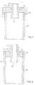
- FIG. 1 illustrates in cross-sectional detail one end of a high pressure arc tube assembly utilizing a cap seal;
- FIG. 2 illustrates in cross-sectional detail one end of a high pressure arc tube assembly utilizing an insert seal.
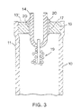
- FIG. 3 illustrates in cross-sectional detail one end of a high pressure arc tube assembly with a niobium feedthrough assembly hermetically sealed with standard frit technology.
- The present invention provides alumina arc tube sealing members used in the formation of sintered hermetic seals, with or without the use of sealing frits or brazing alloys.
- Referring to the drawings, a fritless seal is constructed as shown in Figs. 1 and 2. Fig. 3 Illustrates a seal made with sealing frits.
- The figures illustrate a first end of a high pressure arc discharge
lamp tube assembly 10, wherein the opposite end is identical or similar. The envelope ofassembly 10 is atransparent alumina tube 11. Each end oftube 11 is sealed by a sealing member, which may be formed into acap seal 12 as shown in Fig. 1, or a sealinginsert 13, 13' as shown in Figs. 2 and 3.Sealing members cylindrical metal feedthrough 14. Aninterface 15 betweentube 11 and sealingmember interface 16 between sealingmember feedthrough 14 may be direct or, as in Fig. 3, hermetically sealed by standard frit technology. -
Sealing members cap seal 12 or a sealinginsert 13, 13' with anaxial hole 17. Upon sintering, the volume of the sealingmember member ceramic tube 11; specifically, the outside diameter of the tube when employingcap seal 12, or the inside diameter of the tube when using sealinginsert 13, 13'. In addition, the outside diameter offeedthrough 14 is considered. As is known in the art, the differential shrinkage of the components upon sintering causes an interference fit in which the components are forced together to form a bond. Typically, sealingmembers tube 11 andfeedthrough 14. - Preferably,
interface 15 has between 4 and 8 percent interference fit withtube 11, whileinterface 16 has between 5 and 9 percent interference fit withfeedthrough 14. Most preferably,interface 15 andinterface 16 have interference fits of 4 percent and 5 percent with their respective components, which provides hermetic seals and reduces strain. - The materials of the
tube 11 and sealingmembers tube 11 is a polycrystalline alumina (PCA) arc tube. Standard PCA typically contains about 0.035 percent by weight yttrium oxide and 0.05 percent by weight magnesium oxide as sintering aids. Some PCA is sintered containing only magnesium oxide sintering aids. Sealingmember PCA arc tube 11 andfeedthrough 14. Preferably, sealingmembers arc tube 11 an opaque appearance due to the formation of light scattering second phases, which migrate into the PCA arc tube wall, as described below. Therefore, compositions having between about 0.10 to 0,5 percent by weight yttrium oxide and 0.02 to 0.25 percent by weight magnesium oxide with alumina powder are preferred for formation of sealinginserts 13, 13'. Most preferably, sealing inserts include between about 0.15 to 0.25 percent by weight yttrium oxide and between about 0.05 to 0.1 percent by weight magnesium oxide with alumina powder. - The sealing
members PCA arc tube 11. The assembly is heated until bothtube 11 and sealingmember interface 15. It is noted that the unsintered sealingmember 12 may also be used with analumina arc tube 11 which has been fully sintered. - The
cylindrical metal feedthrough 14 is then positioned directly inaxial hole 17 running through sealingmember cylindrical metal feedthrough 14 because it is refractory, chemically compatible with alumina, and has a similar thermal expansion coefficient to alumina. When not using a sealing frit, thefeedthrough 14 is temporarily held in place whileassembly 10 is heated until bothtube 11 and sealingmember member member feedthrough 14. The sealing member deforms at a lower flow stress than theniobium feedthrough 14 and so deformed slightly and bulges out at theinterface 16 forming a fritless, brazeless hermetic seal. There appears to be both a mechanical and diffusion bond. - Alternatively, standard frit technology may be used to seal
niobium feedthrough 14 within sealing member 13'. Typically, a ring of sealingmaterial 20 is placed aroundaxial hole 17.Niobium feedthrough 14, withelectrode assembly 19 in place, is positioned through the sealing member 13' intotube 11. - The sealing
material 19 is typically a ring pressed from a meltable frit based on calcium aluminate. Compositions useful as sealants for alumina are well known in the art and have been used in conjunction with niobium feedthrough assemblies. The assembly is then heated in the feedthrough region to about 1400°C to melt the sealingmaterial 20 and cause it to flow into the spaces between thefeedthrough 14 and the sealing member 13', thereby providing a hermetic seal. - During the sintering operation, the tube, sealing member and feedthrough are heated at the temperature and time normally used to sinter the type of ceramic materials used in the
tube 11 and sealingmember member PCA art tube 11, and it is impossible to delineate theoriginal inerface 15. This permits fabricating an arc discharge lamp capable of a high cold spot temperature. Further, it is possible to design with less interference fit, which reduces the loss due to arc tub cracking. - Therefore, other sealing temperatures would work as long as The ternary yttrium oxide-magnesium oxide-alumina eutectic temperature of 1,640°C was exceeded and the alumina melting temperature of 2,050°C was not exceeded. The sealing time is adjusted with the sealing. temperature, within the above-noted range, to accomplish the dual objectives of obtaining a highdensity, hermetically tight sintered sealing member and a sufficient bond at each interface to achieve a long life hermetic seal.
- The furnace atmosphere during the sintering is selected not only for the ceramic components, but also to limit embrittlement of the
niobium feedthrough 14. In a preferred embodiment the furnace atmosphere is either vacuum, nitrogen-hydrogen, or hydrogen. - For a high intensity discharge lamp application, such as in a high pressure sodium lamp, the arc
tube sealing member niobium feedthrough 14. Thefeedthrough 14 has anaxial hole 18 into which the electrode assembly is inserted. Typically, the electrode assembly is fitted with a tungsten coil impregnated with a barium-calcium-tungstate electron emissive coating. The slip-fit electrode assembly is inserted into theniobium feedthrough 14, with the electrode tip portion in thearc tube 11, and positioned to give the proper back spacing of the electrode. A hermetic seal is formed. by welding the assembly together. The niobium to niobium weld is typically made by an electron beam welder under vacuum. The beam current is kept sufficiently small to heat the niobium tube locally and to keep the molten zone as small as possible. - The secondary Treating of the niobium to alumina seal is minimal. The
arc tube 11 is typically held in a rotating chuck, or in a similar manner during the niobium to niobium welding operation. This weld could alternatively be produced by well controlled tungsten inert gas (TIG) welding, or by laser welding in an inert, dry, oxiygen-free atmosphere. In an alternative construction, as shown in Fig. 3, anelectrode assembly 19 may be hermetically welded directly to theniobium feedthrough 14. - The
tube 11 is typically then dosed with solid and gaseous fill materials. Preferably, the lamp is completed by filling it with a mercury-sodium amalgam. It is noted, however, that a variety of metal and metal halide fill ingredients may be used due to the direct niobium-to-ceramic sealing which allows the end temperatures to be raised to the upper temperature limit of those materials. - It is noted that substitutions in the basic chemistry of the present sealing member compositions are possible. Magnesium oxide is the classic and best grain growth inhibiting sintering aid for alumina and would therefore, remain in any alternate compositions. Several compounds, however, could be substituted for yttrium oxide, or added to the present composition to give a quaternary blend, including: scandium oxide, lanthanum oxide, praseodymium sesquioxide, europium oxide, gadolinium oxide, terbium, oxide, dysprosium oxide, thulium oxide, ytterbium oxide, zirconium oxide, hafnium oxide, and thorium dioxide. Other compounds such as cerium oxide, neodymium oxide, and the remaining rare earth elements would likely perform satisfactorily from a chemical-microstructure point of view, but they would add color to the body. The present invention will be further illustrated by the following examples.
- An experiment was conducted to determine a preferred composition for translucent Al2O3 arc tube cap seal compositions. The composition of a cap seal was selected based on a evaluation of microstructure, reactivity, and bonding with Al2O3 and Nb. A series of composition were prepared as shown in Table 1.
TABLE 1. TRIAL ALUMINA BASE CAP COMPOSITIONS (WEIGHT PERCENT) Y2O3 MgO Al2O3 Sample 1 0.5 0.05 balance 2 1.0 0.05 balance 3 2.0 0.05 balance 4 5.0 0.05 balance - These blends were made by first dissolving yttrium nitrate and, separately, magnesium nitrate into stock methanol solutions. These solutions were assayed to determine the equivalent concentration upon drying and calcining of Y2O3 and MgO respectively.
- Batches calculated to total 50 g were prepared by first weighing the appropriate quantity of high purity Al2O3 into a polyethylene jar. The appropriate concentration of the stock yttrium nitrate and magnesium nitrate solutions were added. Additional methanol was added to bring the suspension to a consistency of heavy cream (∼100 centipoise). Approximately 12 alumina milling balls were added, and the suspension was rolled on a rolling mill for 1 hour to insure thorough mixing of the components.
- The suspension was dried in a petri dish on a hot plate using a magnetic stirring bar to insure a uniform mix through drying to thick paste consistency. The dish was placed in an oven at 70°C until completely dry. The contents were placed in an alumina crucible and calcined for 2 hours at 1200°C to decompose the nitrates to oxides and obtain some initial reaction of the two additives with Al2O3. The powder was then ground in a boron carbide mortar and pestle and passed through a nylon screen having an aperture of 0.149 mm (a 100 mesh nylon screen). A 1.27 cm (1/2 inch) diameter disc was pressed of each powder composition at 34.5 N/mm2 (5000 psi). The discs were sintered in flowing dry H2 at 1860°C for 1 hour. X-ray diffraction found that the major second phase was Y3Al5O12. The sintered dense discs were cross sectioned and polished for metallographic examination. Photographs of each sample were analyzed by lineal analysis for second phase content. The volume of second phase in ascending order was 6.2%, 9.4%, 12.6% and 26.8%.
- Sample 3, the 2.0% Y2O3 + 0.05% MgO composition, was chosen for further work because it is believed that higher concentrations may be too plastic at the sintering/sealing temperature while lower concentrations could have insufficient liquid phase to penetrate grain boundaries and to react and bond to the Al2O3 arc tube and Nb feedthrough.
- A solid rod of the Sample 3 composition was pressed isostatically at 86.25 N/mm2 (12,500 psi). Caps of the geometry shown in FIG. 1 were machined from the unfired rod to give, upon sealing, interference fits on the fully sintered translucent Al2O3 arc tube and Nb feedthrough of 4%, 4.5%, 5%, 6%, 7%, 8%, 9%, 10%, 12% and 14%. The interferences were selected based on obtaining a hermetic bond and a crack-free component in a typical sealing cycle. It was found that the Al2O3/Al2O3 interface should have an 8% interference while the Al2O3/Nb interface should have a 9% interference.
- Later work using this type seal to make lamps showed that the interference fits could be reduced to 4% and 5% respectively, which still resultd in a hermetic seal, and had a higher yield of crack-free components. Polished sections of these seals were examined by metallography and microprobe techniques. The microstructure was found to be continuous across the original Al2O3/Al2O3 interface. The interface between the sealing cap and Nb exhibited interdiffusion of the components with each other, proving that a strong chemical bond was produced.
- An experiment was conducted to determine if a direct seal could be made to a 0.12 cm (0.048 inch) diameter Nb wire. A disc of Example I, Sample 3 material, 2.0% Y2O3 and 0.05% MgO, was pressed at 34.5 N/mm2 (5000 psi). A hole was drilled having a calculated 9% interference fit, and the Nb wire was inserted in the hole. The assembly was sintered and sealed according to Example I. The seal was found to be uncracked and hermetic, based on a helium leak check. Such an assembly therefore could be utilized in constructing unique high-in-tensity arc discharge lamps.
- An experiment was conducted to determine if the seal composition of Example I could be used in the construction of arc tubes. Two arc tubes of the Example I, Sample 3 composition, 2.0% Y2O3 and 0.05% MgO were pressed and sintered at 1880°C for 2 hours in flowing H2. The total transmittance was only 90% and the in-line, or specular, transmittance was 1%. This is significantly below the 95-97% total and 5-7% normally achieved and considered acceptable in production. Metallography revealed very little residual porosity, but a high concentration of the second phase material, Y3Al5O12. Scattering from the high concentration of the second phase material is believed to be responsible for the low transmission values. These results indicate that the preferred direct sealing member composition is not suitable for production of arc tubes. Further, the present sealing member compositions are different from the prior art describing Y2O3 and MgO sintering aid compositions for translucent PCA arc tubes.
- An experiment was conducted to determine if the preferred composition for cap seals as shown in Figure I could also be used for sealing inserts as shown in Figure 2. A batch of Example I, Sample 3 powder (2.0% Y2O3 + 0.05% MgO, balance Al2O3) was mixed with 0.5% polyvinyl alcohol and 1.5% Carbowax binders and was spray dried in a production spray dryer. Inserts were pressed and employed in sintering regular production PCA 400 watt arc tubes. The seals were hermetic, but the second phase (Y3Al5O12) migrated into the PCA arc tube wall, giving an objectionable opaque appearance.
- Therefore, a series of alternative compositions were prepared as shown in Table 2.
TABLE 2. TRIAL ALUMINA BASE INSERT COMPOSITIONS (WEIGHT PERCENT) Y2O3 MgO Al2O3 Sample 1 0.05 0.08 balance 2 0,10 0.08 balance 3 0.15 0.05 balance 4 0.20 0.05 balance 5 0.25 0.05 balance 6 0.50 0.02 balance - The powder preparation was accomplished as described in Example I. Solid rods were Isostatically pressed at 86.25 N/mm2 (12,500 psi). The rods were then machined into inserts, designed to have a 5-7% interference fit, upon sintering, to full density inside a PCA tube pressed from spray dried Baikowski CR-30 Al2O3 powder, containing 0,035% Y2O3 + 0.05% MgO sintering aids. A typical sintering cycle was 1825°C for 90 minutes in dry H2 followed, without interruption, by 90 minutes in H2 that was bubbled through 23°C H2O. Heating and cooling rates were 17°C/min. The samples were examined, with back lighting, for continuity of seal over the entire seal area. Further, representative seals were sectioned longitudinally and horizontally, polished, and examined metallographically. Intermittent seal voids were detected on the Sample 1 and 2 (0.05 and 0.10% Y2O3) compositions. The higher Y2O3 weight percent compositions had no detected voids, a continuous microstructure across the original interface, and varying concentration of second phase migration into the PCA tube wall, scaling with Y2O3 content. In general, the grain size was larger in the insert than in the PCA wall, with 39 µm and 29 µm being typical grain sizes for the respective components. The large grains in nine insert were appozimately the same size as the large grains in the arc tube wall. Since the large grains are through to be the origin of the strength-limiting flaws, the microstructure of the insert should be nearly equal in strength to the PCA arc tube.
- An experiment was conducted to compare the strength of the various sealing member compositions.
Four-point bend strength tests were conducted at ambient temperature and atmosphere to compare strength results with standard PCA. The results are shown in Table 3.TABLE 3. STRENGTH COMPARISON OF INSERT/SEAL COMPOSITIONS Y2O3 MgO Grain Size Strength Strength (wt%) (wt%) (µm) (N/mm2) (ksi) 0.05 0.05 25.5 273.2±9.0 39.6±1.3 (Standard PCA) 0.10 0.08 31.1 201.5±6.9 29.2±1.0 0.15 0.05 23.4 247.0±11.7 35.8±1.7 0.15 0.05 15.5 245.6±8.3 35.6±1.2 0.15 0.05 24.2 223.6±10.4 32.4±1.5 0.15 0.05 27.0 222.9±6.9 32.3±1.0 2.00 0.05 11.0 249.1±7.6 36.1±1.1 - The higher Y2O3 compositions were slightly weaker than the standard PCS in this test format. This could be partially due to grain size and porosity differences. The reported grain sizes are the average grain sizes, whereas the largest grain sizes may be the controlling feature. It is noteworthy that the smaller grain sizes in the 0.15% Y2O3 compositions had the higher strengths for the series, and the small grain size (15 min. sintering time) 2.0% Y2O3 was also high strength.
- One of the groups of Example V was tested for thermal shock resistance under aggresive second seal thermal cycles designed to crack some, but not all, of the arc tubes. The higher weight percent Y2O3 inserts were compared with a control group of standard PCS inserts processed at the same time. Four different thermal cycles were employed with increasing severity. This test is reported in Table 4.
TABLE 4. COMPARISON OF THERMAL SHOCK RESISTANCE Cycle Percentage Cracked High Y2O3 Standard 1 10.5 15.8 2 15.8 21.1 3 41.8 45.5 4 78.9 78.9 - Based on this test, the high weight percent Y2O3 inserts have a thermal shock resistance that is at least as good as the standard inserts. Either the slightly lower strength observed in Table 3 is too small to show up in a thermal shock test, or the processing of the high weight percent Y2O3 insert and the tube together results in a higher strength microstructure. It is concluded that the high weight percent Y2O3 hermetic insert was suitable mechanically for this application.
- These examples demonstrate that an alumina arc tube sealing member may be formed which permits fabrication of sintered hermetic seals to a translucent alumina arc tube, without the use of sealing frits or brazing alloys. The sealing member also facilitates construction of a hermetic insert in a PCA tube that employs frit in the final sealing of the niobium feedthrough assembly. These compositions allow for formation of sealing members which are similar in strength to the standard PCA sealing members, and have minimal interference fits. The compositions also provide strong mechanical and chemical bonds with both the alumina arc tube and niobium feedthrough. Within the scope of the invention, different compositions are required for cap seals and for sealing inserts. It is noted that the present sealing member compositions are not suitable for formation of PCA arc tubes.
- Alternate seal conscruction designs and sequences are possible, centered around the general theme of a hermetic high temperature seal formed during or after sintering of the PCA arc tube.
- Although particular embodiments of the invention have been described in detail for purposes of illustration, various modifications may be made without departing form the spirit and scope of the present invention.
- The phrase "about 95,0 to about 99,9 percent by weight of highly pure fine alumina" means that a value of 94,95% as well as a value of 99,95% shall be included. Moreover, normal and self-evident tolerances are included.
Claims (15)
- An alumina arc tube sealing member (12; 13; 13') comprising between about 95.0 to about 99.9 percent by weight of highly pure fine alumina doped with between about 0.1 to about 5.0 percent by weight of yttrium oxide, and between about 0.01 to about 0.5 percent by weight of magnesium oxide, and having an axial hole (17) running through the sealing member, in which a cylindrical metal feedthrough (14) is positioned, the feedthrough having a thermal expansion coefficient similar to alumina.
- The alumina arc tube sealing composition of claim 1 further comprising at least one component selected from the group consisting of scandium oxide, lanthanum oxide, praseodymium sesquioxide, europium oxide, gadolinium oxide, terbium oxide, dysprosium oxide, thulium oxide, ytterbium oxide, zirconium oxide, hafnium oxide, and thorium dioxide.
- The alumina arc tube sealing member of claim wherein said member is a cap seal (12) comprising between 2.0 to about 3.0 percent by weight of yttrium oxide and between about 0.05 to about 0.1 percent by weight magnesium oxide.
- The alumina arc tube sealing member of claim 1 wherein said member is a sealing insert (13; 13') comprising between 0.15 percent to about 0.25 percent by weight of yttrium oxide and between about 0.05 to about 0.1 percent by weight magnesium oxide.
- An alumina arc tube sealing member (12; 13; 13') comprising between about 95.0 to about 99.9% by weight of highly pure fine alumina doped with between about 0,01 to about 0.5% by weight of magnesium oxide, and between about 0.01 to about 5,0% by weight of at least one component selected from the group consisting of scandium oxide, lanthanum oxide, praseodymium sesquioxide, europium oxide, gadolinium oxide, terbium oxide, dysprosium oxide, thulium oxide, ytterbium oxide, zirconium oxide, hafnium oxide, and therium dioxide, and having an axial hole (17) running through the sealing member, in which a cylindrical metal feedthrough (14) is positioned, the feedthrough having a thermal expansion coefficient similar to alumina.
- A process comprising:preparing a homogeneous powdery mixture consisting essentially of highly pure fine alumina having a particle size Conventionally suitable for sintering, at least one component selected from the group consisting of yttrium oxide and yttrium compounds capable of being converted to yttrium oxide by calcination in an oxidizing atmosphere, the amount of said component being between about 0.1 to about 5.0 precent by weight of yttrium oxide, and at least one other component selected from the group consisting of magnesium oxide and magnesium compounds capable of being converted to magnesium oxide by calcination in an oxidizing atmosphere, the amount of said other component being between about 0.01 to about 0.5 percent by weight of magnesium oxide;forming a sealing member for alumina arc tubes from said mixture, which step includes forming an axial hole for receipt of a metal feedthrough, wherein said metal is refractory, chemically compatible which said sealing member and has a similar thermal expansion coefficient to alumina; and sealing said alumina arc tube with said sealing member at a temperature between about 1640°C to about 2050°C for a period of time sufficient to obtain a long life, high density, hermetically tight sintered seal.
- The process of claim 6 wherein said sealing member is a cap seal.
- The process of claim 6 wherein said sealing member is a sealing insert.
- The process of claim 7 wherein said homogenous powdery mixture comprises between about 2.0 to about 3.0 percent by weight of yttrium oxide and between about 0.05 to about 0.1 percent by weight magnesium oxide.
- The process of claim 8 wherein said homogeneous powdery mixture comprises between about 0.15 to about 0.5 percent by weight of yttrium oxide and between about 0.05 to about 0.1 percent by weight magnesium oxide.
- The process of claim 6 wherein said metal is niobium.
- The process of claim 6 wherein said sealing member is formed to give, upon sealing, an interference fit with said alumina arc tube of between about 4% to about 14%.
- The process of claim 6 wherein said yttrium compound is yttrium nitrate and the magnesium compound is magnesium nitrate.
- The process of claim 6 wherein said homogeneous powdery mixture also comprises at least one component selected from the group consisting of scandium oxide, lanthanum oxide, praseodymium sesquioxide, europium oxide, gadolinium oxide, terbium oxide, dysprosium oxide, thullium oxide, ytterbium oxide, zirconium oxide, hafnium oxide, and thorium oxide.
- A process comprising:preparing a homogeneous powdery mixture consisting essentially of highly pure fine alumina having a particle size conventionally suitable for sintering, at least one member selected from the group consisting of magnesium oxide and magnesium compounds capable of being converted to magnesium oxide by calcination in an oxidizing atmosphere, the amount of said other member being between about 0.01 to about 0.5% by weight of magnesium oxide, and at least one member selected from the group consisting of scandium oxide, lanthanum oxide, praseodymium sesquioxide, europium oxide, gadolinium oxide, terbium oxide, dysprosium oxide, thulium oxide, ytterbium oxide, zirconium oxide, hafnium oxide, and thorium dioxide, the amount of said member being between about 0.01 to about 5.0% by weight;forming a sealing member for alumina arc tubes from said mixture, which step includes forming an axial hole for receipt of a metal feedthrough, wherein said metal is refractory, chemically compatible with said sealing member, and has a similar thermal expansion coefficient to alumina; andsealing said alumina arc tube with said sealing member at a temperature between about the eutectic forming temperature to about 2,050°C for a period of time sufficient to obtain a long life, high density, hermetically tight sintered seal.
Applications Claiming Priority (3)
| Application Number | Priority Date | Filing Date | Title |
|---|---|---|---|
| US945556 | 1992-09-16 | ||
| US07/945,556 US5426343A (en) | 1992-09-16 | 1992-09-16 | Sealing members for alumina arc tubes and method of making the same |
| PCT/EP1993/002506 WO1994006727A1 (en) | 1992-09-16 | 1993-09-16 | Sealing members for alumina arc tubes and method of making the same |
Publications (2)
| Publication Number | Publication Date |
|---|---|
| EP0660810A1 EP0660810A1 (en) | 1995-07-05 |
| EP0660810B1 true EP0660810B1 (en) | 1996-07-03 |
Family
ID=25483275
Family Applications (1)
| Application Number | Title | Priority Date | Filing Date |
|---|---|---|---|
| EP93920741A Expired - Lifetime EP0660810B1 (en) | 1992-09-16 | 1993-09-16 | Sealing members for alumina arc tubes and method of making the same |
Country Status (7)
| Country | Link |
|---|---|
| US (2) | US5426343A (en) |
| EP (1) | EP0660810B1 (en) |
| JP (1) | JPH08501270A (en) |
| CA (1) | CA2106156A1 (en) |
| DE (1) | DE69303489T2 (en) |
| HU (1) | HU218226B (en) |
| WO (1) | WO1994006727A1 (en) |
Families Citing this family (66)
| Publication number | Priority date | Publication date | Assignee | Title |
|---|---|---|---|---|
| EP0657399B1 (en) * | 1993-12-10 | 1997-07-16 | Patent-Treuhand-Gesellschaft für elektrische Glühlampen mbH | High-pressure discharge lamp having a ceramic discharge vessel, sintered body suitable therefor, and methods for producing the said sintered body |
| US5621275A (en) * | 1995-08-01 | 1997-04-15 | Osram Sylvania Inc. | Arc tube for electrodeless lamp |
| US5592048A (en) * | 1995-08-18 | 1997-01-07 | Osram Sylvania Inc. | Arc tube electrodeless high pressure sodium lamp |
| US5791551A (en) * | 1996-07-24 | 1998-08-11 | Owens Corning Fiberglas Technology, Inc. | Vacuum insulation vessels and methods of making same |
| US5631201A (en) * | 1996-07-29 | 1997-05-20 | Osram Sylvania Inc. | Translucent polycrystalline alumina and method of making same |
| US6027389A (en) * | 1996-08-30 | 2000-02-22 | Ngk Insulators, Ltd. | Production of ceramic tubes for metal halide lamps |
| JPH1167153A (en) * | 1997-08-21 | 1999-03-09 | Koito Mfg Co Ltd | Metal halide lamp |
| EP0960432B1 (en) * | 1997-12-16 | 2004-07-14 | Koninklijke Philips Electronics N.V. | High-pressure discharge lamp |
| US6126889A (en) * | 1998-02-11 | 2000-10-03 | General Electric Company | Process of preparing monolithic seal for sapphire CMH lamp |
| US6583563B1 (en) * | 1998-04-28 | 2003-06-24 | General Electric Company | Ceramic discharge chamber for a discharge lamp |
| US7297037B2 (en) * | 1998-04-28 | 2007-11-20 | General Electric Company | Ceramic discharge chamber for a discharge lamp |
| US6004503A (en) * | 1998-10-02 | 1999-12-21 | Osram Sylvania Inc. | Method of making a ceramic arc tube for metal halide lamps |
| JP2000277013A (en) * | 1998-11-30 | 2000-10-06 | Osram Sylvania Inc | Manufacturing method of ceramic arc tube for metal halide lamp |
| US6446700B1 (en) * | 1999-07-19 | 2002-09-10 | General Electric Company | Floating insulating baffle for high gradient casting |
| US6126887A (en) * | 1999-07-30 | 2000-10-03 | General Electric Company | Method of manufacture of ceramic ARC tubes |
| JP4613408B2 (en) * | 1999-10-15 | 2011-01-19 | 日本碍子株式会社 | Manufacturing method of arc tube for high pressure discharge lamp |
| US6346495B1 (en) | 1999-12-30 | 2002-02-12 | General Electric Company | Die pressing arctube bodies |
| US6592808B1 (en) * | 1999-12-30 | 2003-07-15 | General Electric Company | Cermet sintering of ceramic discharge chambers |
| WO2001067480A1 (en) * | 2000-03-09 | 2001-09-13 | Advanced Lighting Technologies, Inc. | A solid lamp fill material and method of dosing hid lamps |
| US6830495B2 (en) * | 2000-03-09 | 2004-12-14 | Advanced Lighting Technologies, Inc. | Solid lamp fill material and method of dosing HID lamps |
| US6661175B2 (en) | 2000-03-09 | 2003-12-09 | Advanced Lighting Technologies, Inc. | Solid lamp fill material and method of dosing hid lamps |
| DE60117486T2 (en) * | 2000-08-23 | 2006-11-16 | General Electric Co. | Injection molded ceramic metal halide arc tube with a non-tapered end |
| WO2002071442A1 (en) * | 2000-11-06 | 2002-09-12 | General Electric Company | Ceramic discharge chamber for a discharge lamp and methods of making it |
| US6731066B2 (en) * | 2001-02-23 | 2004-05-04 | Osram Sylvania Inc. | Ceramic arc tube assembly |
| US6873108B2 (en) * | 2001-09-14 | 2005-03-29 | Osram Sylvania Inc. | Monolithic seal for a sapphire metal halide lamp |
| JP3960796B2 (en) * | 2001-12-27 | 2007-08-15 | 日本碍子株式会社 | Joint, high pressure discharge lamp assembly and high pressure discharge lamp |
| US20030150844A1 (en) * | 2002-02-14 | 2003-08-14 | Siemens Vdo Automotive, Inc. | Method and apparatus for laser welding hoses in an air induction system |
| JP4131240B2 (en) * | 2002-03-07 | 2008-08-13 | 日本碍子株式会社 | Luminescent vessel for high pressure discharge lamp and method for producing polycrystalline transparent alumina sintered body |
| JP2004025198A (en) * | 2002-06-21 | 2004-01-29 | Aisan Ind Co Ltd | Diffusion bonding method, bonded parts, method of manufacturing engine valve, and engine valve |
| US7253122B2 (en) * | 2002-08-28 | 2007-08-07 | Micron Technology, Inc. | Systems and methods for forming metal oxides using metal diketonates and/or ketoimines |
| US7087481B2 (en) * | 2002-08-28 | 2006-08-08 | Micron Technology, Inc. | Systems and methods for forming metal oxides using metal compounds containing aminosilane ligands |
| US6984592B2 (en) | 2002-08-28 | 2006-01-10 | Micron Technology, Inc. | Systems and methods for forming metal-doped alumina |
| US7218707B2 (en) * | 2002-09-09 | 2007-05-15 | Comet Holding Ag | High-voltage vacuum tube |
| US7215081B2 (en) * | 2002-12-18 | 2007-05-08 | General Electric Company | HID lamp having material free dosing tube seal |
| US7132797B2 (en) * | 2002-12-18 | 2006-11-07 | General Electric Company | Hermetical end-to-end sealing techniques and lamp having uniquely sealed components |
| US7839089B2 (en) * | 2002-12-18 | 2010-11-23 | General Electric Company | Hermetical lamp sealing techniques and lamp having uniquely sealed components |
| JP3953431B2 (en) * | 2003-03-10 | 2007-08-08 | 日本碍子株式会社 | Luminescent container for high pressure discharge lamp and high pressure discharge lamp |
| DE10335224A1 (en) * | 2003-07-30 | 2005-03-24 | Universität Bremen | Method for production of a molded body from ceramic material using metal powder and a colloidal sol useful in space shuttle-, microsystem-, fireproofing-, and/or foundry-, and/or biotechnology technology, e.g. chromatography |
| US20060001346A1 (en) * | 2004-06-30 | 2006-01-05 | Vartuli James S | System and method for design of projector lamp |
| US7358666B2 (en) | 2004-09-29 | 2008-04-15 | General Electric Company | System and method for sealing high intensity discharge lamps |
| US7615929B2 (en) | 2005-06-30 | 2009-11-10 | General Electric Company | Ceramic lamps and methods of making same |
| US7432657B2 (en) * | 2005-06-30 | 2008-10-07 | General Electric Company | Ceramic lamp having shielded niobium end cap and systems and methods therewith |
| US7852006B2 (en) | 2005-06-30 | 2010-12-14 | General Electric Company | Ceramic lamp having molybdenum-rhenium end cap and systems and methods therewith |
| CN1903784B (en) * | 2005-07-29 | 2010-04-14 | 中国科学院上海硅酸盐研究所 | Preparation method of light-transmitting alumina ceramics |
| GB2428867A (en) * | 2005-08-05 | 2007-02-07 | Gen Electric | A one-piece end plug with tapered leg portion for a ceramic arc tube |
| US8770324B2 (en) * | 2008-06-10 | 2014-07-08 | Baker Hughes Incorporated | Earth-boring tools including sinterbonded components and partially formed tools configured to be sinterbonded |
| US7913779B2 (en) * | 2005-11-10 | 2011-03-29 | Baker Hughes Incorporated | Earth-boring rotary drill bits including bit bodies having boron carbide particles in aluminum or aluminum-based alloy matrix materials, and methods for forming such bits |
| US7784567B2 (en) * | 2005-11-10 | 2010-08-31 | Baker Hughes Incorporated | Earth-boring rotary drill bits including bit bodies comprising reinforced titanium or titanium-based alloy matrix materials, and methods for forming such bits |
| US7807099B2 (en) | 2005-11-10 | 2010-10-05 | Baker Hughes Incorporated | Method for forming earth-boring tools comprising silicon carbide composite materials |
| US7378799B2 (en) * | 2005-11-29 | 2008-05-27 | General Electric Company | High intensity discharge lamp having compliant seal |
| US8272295B2 (en) * | 2006-12-07 | 2012-09-25 | Baker Hughes Incorporated | Displacement members and intermediate structures for use in forming at least a portion of bit bodies of earth-boring rotary drill bits |
| US7841259B2 (en) | 2006-12-27 | 2010-11-30 | Baker Hughes Incorporated | Methods of forming bit bodies |
| US8299709B2 (en) * | 2007-02-05 | 2012-10-30 | General Electric Company | Lamp having axially and radially graded structure |
| US7741780B2 (en) * | 2007-02-26 | 2010-06-22 | Osram Sylvania Inc. | Ceramic discharge vessel having a sealing composition |
| US8092875B2 (en) * | 2007-04-03 | 2012-01-10 | Ngk Insulators, Ltd. | Composite luminous vessels |
| US7678725B2 (en) * | 2007-05-14 | 2010-03-16 | General Electric Company | Translucent polycrystalline alumina ceramic |
| US20080283522A1 (en) * | 2007-05-14 | 2008-11-20 | Shuyl Qin | Translucent polycrystalline alumina ceramic |
| US8310157B2 (en) * | 2008-09-10 | 2012-11-13 | General Electric Company | Lamp having metal conductor bonded to ceramic leg member |
| JP2010287555A (en) * | 2009-05-15 | 2010-12-24 | Toshiba Lighting & Technology Corp | High pressure discharge lamp |
| US20110177747A1 (en) * | 2010-01-21 | 2011-07-21 | Thomas Patrician | Method of Making a Fritless Seal in a Ceramic Arc Tube for a Discharge Lamp |
| DE102010003302B4 (en) * | 2010-03-25 | 2020-07-30 | Huber+Suhner Cube Optics Ag | Method of making a bushing for an optical conductor |
| US8319431B2 (en) | 2010-06-25 | 2012-11-27 | General Electric Company | Ceramic arc tube for a discharge lamp and method of making same |
| EP2748833B1 (en) | 2011-12-02 | 2015-01-07 | Koninklijke Philips N.V. | High-pressure gas discharge lamp |
| US9212435B2 (en) | 2012-06-29 | 2015-12-15 | Weyerhaeuser NRCompany | Pulp and fibrillated fiber composite |
| EP2880678A2 (en) | 2012-08-03 | 2015-06-10 | Koninklijke Philips N.V. | High pressure discharge lamp with a uv-enhancer, and manufacture method therefor |
| US10090210B2 (en) * | 2015-10-01 | 2018-10-02 | Sensor Electronic Technology, Inc. | Material growth with temperature controlled layer |
Family Cites Families (21)
| Publication number | Priority date | Publication date | Assignee | Title |
|---|---|---|---|---|
| US3281309A (en) * | 1961-12-12 | 1966-10-25 | Gen Electric | Ceramic bonding |
| GB1107764A (en) * | 1965-01-07 | 1968-03-27 | Gen Electric Co Ltd | Improvements in or relating to the closure of tubes of refractory oxide material |
| US3363134A (en) * | 1965-12-08 | 1968-01-09 | Gen Electric | Arc discharge lamp having polycrystalline ceramic arc tube |
| US4004173A (en) * | 1965-12-27 | 1977-01-18 | Sydney Alfred Richard Rigden | Niobium alumina sealing and product produced thereby |
| US3441421A (en) * | 1966-10-24 | 1969-04-29 | Gen Electric | Calcia-magnesia-alumina seal compositions |
| US3448319A (en) * | 1966-10-31 | 1969-06-03 | Gen Electric | Niobium end seal |
| US3588573A (en) * | 1967-12-29 | 1971-06-28 | Westinghouse Electric Corp | Alumina-rare earth oxide ceramic to metal seals for containing high temperature vapors |
| JPS4939885B1 (en) * | 1968-08-19 | 1974-10-29 | ||
| SU617438A1 (en) * | 1976-04-05 | 1978-07-30 | Предприятие П/Я А-1857 | Vacuum-tight ceramics |
| JPS56140932A (en) * | 1980-04-07 | 1981-11-04 | Toray Ind Inc | Isolation of cyclohexene by adsorption |
| JPS6048466B2 (en) * | 1980-05-15 | 1985-10-28 | 日本碍子株式会社 | Manufacturing method of polycrystalline transparent alumina sintered body |
| US4545799A (en) * | 1983-09-06 | 1985-10-08 | Gte Laboratories Incorporated | Method of making direct seal between niobium and ceramics |
| US4537323A (en) * | 1984-01-09 | 1985-08-27 | Gte Laboratories Incorporated | Mo-Ti members with non-metallic sintering aids |
| US4762655A (en) * | 1985-11-27 | 1988-08-09 | Gte Laboratories Incorporated | Method of sintering translucent alumina |
| US4797238A (en) * | 1985-11-27 | 1989-01-10 | Gte Laboratories Incorporated | Rapid-sintering of alumina |
| JPS62170129A (en) * | 1986-01-21 | 1987-07-27 | Ngk Insulators Ltd | Manufacture of ceramic luminous tube for high pressure metallic vapor discharge lamp |
| DE68927594T2 (en) * | 1988-05-13 | 1997-07-24 | Gte Prod Corp | Arc bulb for high pressure metal vapor discharge lamps, lamp with such a bulb and method of manufacture |
| US4948538A (en) * | 1988-10-11 | 1990-08-14 | Gte Laboratories Incorporated | Method of making translucent alumina articles |
| US5057048A (en) * | 1989-10-23 | 1991-10-15 | Gte Laboratories Incorporated | Niobium-ceramic feedthrough assembly and ductility-preserving sealing process |
| US5095246A (en) * | 1989-10-23 | 1992-03-10 | Gte Laboratories Incorporated | Niobium-ceramic feedthrough assembly |
| DE9012200U1 (en) * | 1990-08-24 | 1991-12-19 | Patent-Treuhand-Gesellschaft für elektrische Glühlampen mbH, 8000 München | High pressure discharge lamp |
-
1992
- 1992-09-16 US US07/945,556 patent/US5426343A/en not_active Expired - Lifetime
-
1993
- 1993-09-14 CA CA002106156A patent/CA2106156A1/en not_active Abandoned
- 1993-09-16 WO PCT/EP1993/002506 patent/WO1994006727A1/en not_active Ceased
- 1993-09-16 JP JP6507796A patent/JPH08501270A/en active Pending
- 1993-09-16 HU HU9500747A patent/HU218226B/en not_active IP Right Cessation
- 1993-09-16 EP EP93920741A patent/EP0660810B1/en not_active Expired - Lifetime
- 1993-09-16 DE DE69303489T patent/DE69303489T2/en not_active Expired - Fee Related
-
1995
- 1995-03-28 US US08/415,139 patent/US5725827A/en not_active Expired - Lifetime
Also Published As
| Publication number | Publication date |
|---|---|
| HUT70344A (en) | 1995-09-28 |
| US5426343A (en) | 1995-06-20 |
| CA2106156A1 (en) | 1994-03-17 |
| US5725827A (en) | 1998-03-10 |
| HU9500747D0 (en) | 1995-05-29 |
| WO1994006727A1 (en) | 1994-03-31 |
| DE69303489T2 (en) | 1997-01-30 |
| HU218226B (en) | 2000-06-28 |
| JPH08501270A (en) | 1996-02-13 |
| EP0660810A1 (en) | 1995-07-05 |
| DE69303489D1 (en) | 1996-08-08 |
Similar Documents
| Publication | Publication Date | Title |
|---|---|---|
| US5725827A (en) | Sealing members for alumina arc tubes and method of making same | |
| EP0136505B1 (en) | Direct seal between niobium and ceramics | |
| US5404078A (en) | High-pressure discharge lamp and method of manufacture | |
| EP0982278B1 (en) | Joined bodies, high-pressure discharge lamps and a method for manufacturing the same | |
| US3564328A (en) | Ceramic articles and method of fabrication | |
| JPH07192698A (en) | Metal halide discharge lamp with ceramic discharge vessel and method of manufacturing the same | |
| US3448319A (en) | Niobium end seal | |
| US6635993B1 (en) | Joined bodies, high-pressure discharge lamps and a method for manufacturing the same | |
| EP0055532A1 (en) | Method of producing a discharge lamp and discharge lamp produced thereby | |
| US20020033671A1 (en) | Joined body and a high pressure discharge lamp | |
| EP0052843B1 (en) | Vacuum-tight assembly | |
| US4537323A (en) | Mo-Ti members with non-metallic sintering aids | |
| US7126280B2 (en) | Joined bodies, assemblies for high pressure discharge lamps and high pressure discharge lamps | |
| US6812642B1 (en) | Joined body and a high-pressure discharge lamp | |
| US7132798B2 (en) | Joined bodies, high pressure discharge lamps and assemblies therefor | |
| US7741780B2 (en) | Ceramic discharge vessel having a sealing composition | |
| EP1170770B1 (en) | Joined bodies and high-pressure discharge lamps | |
| US5095246A (en) | Niobium-ceramic feedthrough assembly | |
| US6850009B2 (en) | Joined body and high pressure discharge lamp | |
| US4330629A (en) | Heat-resistant sealing materials |
Legal Events
| Date | Code | Title | Description |
|---|---|---|---|
| PUAI | Public reference made under article 153(3) epc to a published international application that has entered the european phase |
Free format text: ORIGINAL CODE: 0009012 |
|
| 17P | Request for examination filed |
Effective date: 19950207 |
|
| AK | Designated contracting states |
Kind code of ref document: A1 Designated state(s): BE DE FR GB IT NL |
|
| 17Q | First examination report despatched |
Effective date: 19951012 |
|
| GRAH | Despatch of communication of intention to grant a patent |
Free format text: ORIGINAL CODE: EPIDOS IGRA |
|
| GRAH | Despatch of communication of intention to grant a patent |
Free format text: ORIGINAL CODE: EPIDOS IGRA |
|
| GRAA | (expected) grant |
Free format text: ORIGINAL CODE: 0009210 |
|
| AK | Designated contracting states |
Kind code of ref document: B1 Designated state(s): BE DE FR GB IT NL |
|
| REF | Corresponds to: |
Ref document number: 69303489 Country of ref document: DE Date of ref document: 19960808 |
|
| ITF | It: translation for a ep patent filed | ||
| ET | Fr: translation filed | ||
| PLBE | No opposition filed within time limit |
Free format text: ORIGINAL CODE: 0009261 |
|
| STAA | Information on the status of an ep patent application or granted ep patent |
Free format text: STATUS: NO OPPOSITION FILED WITHIN TIME LIMIT |
|
| 26N | No opposition filed | ||
| REG | Reference to a national code |
Ref country code: GB Ref legal event code: IF02 |
|
| PGFP | Annual fee paid to national office [announced via postgrant information from national office to epo] |
Ref country code: GB Payment date: 20020910 Year of fee payment: 10 |
|
| PGFP | Annual fee paid to national office [announced via postgrant information from national office to epo] |
Ref country code: BE Payment date: 20020923 Year of fee payment: 10 |
|
| PGFP | Annual fee paid to national office [announced via postgrant information from national office to epo] |
Ref country code: FR Payment date: 20020930 Year of fee payment: 10 |
|
| PG25 | Lapsed in a contracting state [announced via postgrant information from national office to epo] |
Ref country code: GB Free format text: LAPSE BECAUSE OF NON-PAYMENT OF DUE FEES Effective date: 20030916 |
|
| PG25 | Lapsed in a contracting state [announced via postgrant information from national office to epo] |
Ref country code: BE Free format text: LAPSE BECAUSE OF NON-PAYMENT OF DUE FEES Effective date: 20030930 |
|
| BERE | Be: lapsed |
Owner name: *PATENT-TREUHAND-G.- FUR ELEKTRISCHE GLUHLAMPEN M. Effective date: 20030930 |
|
| GBPC | Gb: european patent ceased through non-payment of renewal fee |
Effective date: 20030916 |
|
| PG25 | Lapsed in a contracting state [announced via postgrant information from national office to epo] |
Ref country code: FR Free format text: LAPSE BECAUSE OF NON-PAYMENT OF DUE FEES Effective date: 20040528 |
|
| REG | Reference to a national code |
Ref country code: FR Ref legal event code: ST |
|
| PG25 | Lapsed in a contracting state [announced via postgrant information from national office to epo] |
Ref country code: IT Free format text: LAPSE BECAUSE OF NON-PAYMENT OF DUE FEES;WARNING: LAPSES OF ITALIAN PATENTS WITH EFFECTIVE DATE BEFORE 2007 MAY HAVE OCCURRED AT ANY TIME BEFORE 2007. THE CORRECT EFFECTIVE DATE MAY BE DIFFERENT FROM THE ONE RECORDED. Effective date: 20050916 |
|
| PGFP | Annual fee paid to national office [announced via postgrant information from national office to epo] |
Ref country code: NL Payment date: 20060911 Year of fee payment: 14 |
|
| PG25 | Lapsed in a contracting state [announced via postgrant information from national office to epo] |
Ref country code: NL Free format text: LAPSE BECAUSE OF NON-PAYMENT OF DUE FEES Effective date: 20080401 |
|
| NLV4 | Nl: lapsed or anulled due to non-payment of the annual fee |
Effective date: 20080401 |
|
| PGFP | Annual fee paid to national office [announced via postgrant information from national office to epo] |
Ref country code: DE Payment date: 20081121 Year of fee payment: 16 |
|
| PG25 | Lapsed in a contracting state [announced via postgrant information from national office to epo] |
Ref country code: DE Free format text: LAPSE BECAUSE OF NON-PAYMENT OF DUE FEES Effective date: 20100401 |