EP0660335A1 - Vorrichtung zur Vermeidung von Überdrücken in Lagerbehältern mit Wasserstoff entwickelndem Inhalt - Google Patents
Vorrichtung zur Vermeidung von Überdrücken in Lagerbehältern mit Wasserstoff entwickelndem Inhalt Download PDFInfo
- Publication number
- EP0660335A1 EP0660335A1 EP94119896A EP94119896A EP0660335A1 EP 0660335 A1 EP0660335 A1 EP 0660335A1 EP 94119896 A EP94119896 A EP 94119896A EP 94119896 A EP94119896 A EP 94119896A EP 0660335 A1 EP0660335 A1 EP 0660335A1
- Authority
- EP
- European Patent Office
- Prior art keywords
- container
- hydrogen
- bursting disc
- storage containers
- water
- Prior art date
- Legal status (The legal status is an assumption and is not a legal conclusion. Google has not performed a legal analysis and makes no representation as to the accuracy of the status listed.)
- Granted
Links
Images
Classifications
-
- G—PHYSICS
- G21—NUCLEAR PHYSICS; NUCLEAR ENGINEERING
- G21F—PROTECTION AGAINST X-RADIATION, GAMMA RADIATION, CORPUSCULAR RADIATION OR PARTICLE BOMBARDMENT; TREATING RADIOACTIVELY CONTAMINATED MATERIAL; DECONTAMINATION ARRANGEMENTS THEREFOR
- G21F5/00—Transportable or portable shielded containers
- G21F5/06—Details of, or accessories to, the containers
Definitions
- the invention relates to a device for avoiding excess pressures in storage containers for hydrogen-developing, in particular radioactive, waste materials, with a container for converting hydrogen into water containing a container.
- Radioactive waste is stored in closed containers for long periods. Due to radiolytic decomposition and as a result of electrochemical reactions, hydrogen is generated in radioactive waste, especially in those with highly compressed radioactive mixed waste. For example, Release 100% of highly compressed radioactive mixed wastes stored in conventional containers of 200 l within 100 days up to 1300 l of hydrogen. This gas development can lead to considerable overpressure and thus to bulges and / or leaks in the respective waste containers. When storing radioactive waste containers, however, their integrity must be guaranteed and furthermore it must be ensured that no further danger from the escape of hydrogen and possibly detonating gas formation can occur.
- R.Köster et.al. DE 39 04 149 A1 describes an arrangement provided in a passage opening of the container or lid, which contains a filling material between gas-permeable limits, which contributes to the catalytic oxidation of hydrogen Storage temperature is enabled.
- the water formed can escape unhindered from the container.
- this problem solution does not take into account the fact that water containing tritium is formed and can be released to the surroundings of the container.
- a catalyst pack provided with an additional desiccant in a gas-permeable envelope has been known for some time (DE 2856243 C2), which can be found at possible exit points of containers, e.g. can be provided sealingly below the container lid, but the usability of this arrangement, which is accessible from the start, does not appear to be guaranteed over long periods.
- a function of reducing the pressure in the container is not mentioned in DE 28 56 243 C2.
- the aim of the invention is now an arrangement with which a useful means for reducing pressure in the event of hydrogen evolution in the closed container is available even over long periods.
- the device according to the invention of the type mentioned at the outset is characterized in that the container has both means for converting the hydrogen into water and drying agent in a gas-tight space which is connected to the environment via a rupture disk.
- Such a bursting unit integrated in the waste container gives a previous one in particular when a certain internal container pressure is exceeded Shielding gas stored combination of hydrogen / oxygen recombination catalyst or water-forming chemical oxidizing agent and a desiccant free. Both components are effective both at room temperature and at final storage temperature.
- the bursting unit protects the catalytic converter or the oxidizing agent and desiccant from undesired contact with inactivating waste components until the need is reached.
- the bursting unit is advantageously screwed or glued to the inside of the container lid with the rupture disk pointing upwards or downwards. However, it can also be otherwise fixed in the container or placed without attachment and in particular mechanically protected by an excellent grid.
- the bursting unit essentially consists of a cup-shaped container 2 with a closed bottom.
- blind holes and through holes are made distributed over the circumference.
- the blind holes serve to fasten the circular cover 12 and the underlying sealing washer 15 by means of the washers 13 and screws 14 .
- the through bores receive threaded rods 23 embedded in the container lid 1 , via which the entire bursting unit is fastened to the container lid by means of the washers 18 and nuts 19 .
- the lid 12 has an opening in which the rupture disc 17 and one arranged above it Protective grille 16 are attached.
- rupture disks made of graphite or graphite coated on one or both sides with PTFE for example type HYKARB from Ralph Coidan Equipment Ltd., in particular at 150 to 200 mbar differential pressure. (Cleveland, USA), rupture disks made of various metals or alloys, e.g. type BS & B from Bormann & Neupert (Düsseldorf), as well as rupture disks made of PTFE or Teflon®, e.g. type COV from Strikomaschinestechnik (Wiehl) have proven to be suitable.
- desiccants Inside the container 2 there are two layers of desiccants with different effects below the water vapor permeable separating layers 4 and 6 .
- desiccants are molecular sieves, dewatered aquo complexing agents, such as copper sulfate, or hygroscopic chemicals such as calcium chloride, magnesium sulfate or phosphorus pentoxide, optionally on a carrier material.
- a layer of a chemical oxidizing agent in particular an oxide with a high oxidation potential, which is held by the gas-permeable separating layer 21 , above the separating layer 6 .
- a chemical oxidizing agent in particular an oxide with a high oxidation potential
- manganese dioxide activated with traces of silver is particularly effective as an oxidizing agent, which can be used as a powder or in pressed form.
- spacer rings 3 , 5 and 20 , 22 or 24 , 8 and 10 To fix the separating layers 4 and 6 and the separating layer 21 or the nets 7 and 8 are used in the Container 2 inserted spacer rings 3 , 5 and 20 , 22 or 24 , 8 and 10 .
- the flexible ring 11 located between spacer ring 20 ( version A ) or 10 ( version B ) and sealing washer 15 serves to compensate for tolerances in the thickness of the spacer rings.
Landscapes
- Physics & Mathematics (AREA)
- Engineering & Computer Science (AREA)
- General Engineering & Computer Science (AREA)
- High Energy & Nuclear Physics (AREA)
- Packages (AREA)
- Processing Of Solid Wastes (AREA)
- Closures For Containers (AREA)
- Filling Or Discharging Of Gas Storage Vessels (AREA)
Abstract
Description
- Die Erfindung bezieht sich auf eine Vorrichtung zur Vermeidung von Überdrücken in Lagerbehältern für Wasserstoff entwickelnde, insbesondere radioaktive Abfallstoffe mit einem in den Behälter einbezogenen, Mittel zur Umwandlung von Wasserstoff in Wasser aufweisenden Behältnis.
- Radioaktive Abfälle werden über längere Zeiten hinweg in geschlossenen Behältern gelagert. Aufgrund radiolytischer Zersetzung sowie infolge elektrochemischer Reaktionen entsteht in radioaktiven Abfällen, insbesondere in solchen mit hochverpreßten radioaktiven Mischabfällen, Wasserstoff. So können z.B. in konventionellen Behältern von 200 l gelagerte hochverpreßte radioaktive Mischabfälle innerhalb von 100 Tagen bis zu 1300 l Wasserstoff freisetzen. Diese Gasentwicklung kann zu beträchtlichem Überdruck und damit zu Aufwölbungen und/oder Leckagen der jeweiligen Abfallbehälter führen. Bei der Lagerung radioaktiver Abfallgebinde muß aber deren Integrität gewährleistet und ferner sichergestellt werden, daß keine weitere Gefährdung durch das Entweichen von Wasserstoff und ggf. Knallgasbildung auftreten kann.
- Zur Reduzierung des in radioaktiven Abfallgebinden durch Wasserstoff verursachten Innendrucks wird bereits von R.Köster et.al. in der DE 39 04 149 A1 eine in einer Durchlaßöffnung von Behälter oder Deckel vorgesehene Anordnung beschrieben, die zwischen gasdurchlässigen Begrenzungen ein Füllmaterial enthält, das zur katalytischen Oxidation von Wasserstoff bei Lagertemperatur befähigt ist. Das dabei gebildete Wasser kann dabei ungehindert aus dem Behälter entweichen. Mit einer solchen Anordnung ist die sicherheitstechnische Barrierefunktion des Behälters für radioaktive Gase oder Dämpfe aber nicht mehr erfüllt. Insbesondere berücksichtigt diese Problemlösung nicht, daß tritiumhaltiges Wasser entstehen und an die Umgebung des Behälters abgegeben werden kann.
- Eine mit zusätzlichem Trockenmittel versehene Katalysatorpackung in gasdurchlässiger Hülle ist zwar schon länger bekannt (DE 2856243 C2) die an möglichen Austrittsstellen von Behältern wie z.B. unterhalb des Behälterdeckels abdichtend vorgesehen sein kann, jedoch erscheint die Brauchbarkeit dieser von Anfang an zugänglichen Anordnung über lange Zeiten hinweg nicht unbedingt gewährleistet. Eine Funktion der Druckminderung im Behälter ist in der DE 28 56 243 C2 nicht erwähnt.
- Ziel der Erfindung ist nun eine Anordnung mit der auch über längere Zeiten hinweg ein brauchbares Mittel zum Druckabbau bei Wasserstoff-Entwicklung im geschlossenen Behälter zur Verfügung steht.
- Zu diesem Zweck ist die erfindungsgemäße Vorrichtung der eingangs genannten Art dadurch gekennzeichnet, daß das Behältnis sowohl Mittel zur Umsetzung des Wasserstoffs in Wasser als auch Trockenmittel in einem in sich gasdicht abgeschlossenen Raum aufweist, der mit der Umgebung über eine Berstscheibe in Verbindung steht.
- Weitere Besonderheiten der Erfindung ergeben sich aus den Unteransprüchen und der nachfolgenden Beschreibung.
- Eine solche in den Abfallbehälter integrierte Bersteinheit gibt bei Überschreiten eines bestimmten Behälterinnendruckes eine zuvor insbesonders unter Schutzgas gelagerte Kombination aus Wasserstoff/Sauerstoff-Rekombinationskatalysator bzw. wasserbildendem chemischen Oxidationsmittel und einem Trockenmittel frei. Beide Komponenten sind sowohl bei Raumtemperatur als auch bei Endlagertemperatur wirksam. Die Bersteinheit schützt den Katalysator bzw. das Oxidationsmittel und Trockenmittel bis zum Erreichen des Bedarfsfalles vor unerwünschtem Kontakt mit inaktivierenden Abfallkomponenten. Im Hinblick auf die Minimierung des freien Behältervolumens wird die Bersteinheit vorteilhaft an der Innenseite des Behälterdeckels mit nach oben oder nach unten zeigender Berstscheibe verschraubt oder verklebt. Sie kann aber auch anderweitig im Behälter fixiert oder ohne Befestigung plaziert und insbesondere durch ein hervorragendes Gitter mechanisch geschützt sein.
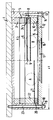
- Im folgenden wird die Erfindung anhand der beigefügten Zeichnung näher erläutert. Diese zeigt zwei Versionen A und B einer an der Innenseite des Behälterdeckels mit nach unten zeigender Berstscheibe hängend angeordneten Bersteinheit.
- Gemäß der Version A besteht die Bersteinheit im wesentlichen aus einem napfförmigen Behältnis 2 mit verschlossenem Boden. Im Rand des Behältnisses 2 sind über den Umfang verteilt Sacklochbohrungen und durchgehende Bohrungen eingebracht. Die Sacklochbohrungen dienen der Befestigung des kreisförmigen Deckels 12 und der darunterliegenden Dichtscheibe 15 mittels der Scheiben 13 und Schrauben 14. Die durchgehenden Bohrungen nehmen in den Behälterdeckel 1 eingelassene Gewindestangen 23 auf, über die die gesamte Bersteinheit mittels der Scheiben 18 und Muttern 19 am Behälterdeckel befestigt ist.
- Der Deckel 12 besitzt eine Öffnung, in der die Berstscheibe 17 sowie ein darüber angeordnetes Schutzgitter 16 befestigt sind. Bei Versuchen haben sich insbesondere bei 150 bis 200 mbar Differenzdruck brechende Berstscheiben aus Graphit oder ein- bzw. doppelseitig mit PTFE beschichtetem Graphit, z.B. Typ HYKARB der Ralph Coidan Equipment Ltd. (Cleveland, USA), Berstscheiben aus verschiedenen Metallen oder Legierungen, z.B. Typ BS & B der Firma Bormann & Neupert (Düsseldorf), sowie Berstscheiben aus PTFE bzw. Teflon®, z.B. Typ COV der Firma Striko Verfahrenstechnik (Wiehl) als geeignet erwiesen. Im Inneren des Behältnisses 2 befinden sich unterhalb der wasserdampfdurchlässigen Trennschichten 4 und 6 zwei Lagen verschieden wirkender Trockenmittel. Gut geeignete Trockenmittel sind außer Silicagel Molekularsiebe, entwässerte Aquokomplexbildner, wie z.B. Kupfersulfat, oder hygroskopische Chemikalien wie Calciumchlorid, Magnesiumsulfat oder Phosphorpentoxid ggf. auf Trägermaterial.
- Oberhalb der Trennschicht 6 befindet sich in Version A der Bersteinheit eine Lage aus einem chemischen Oxidationsmittel, insbesondere einem Oxid mit hohem Oxidationspotential, die von der gasdurchlässigen Trennschicht 21 gehalten wird. Als Oxidationsmittel ist nach bisherigen Versuchen insbesondere mit Silberspuren aktiviertes Mangandioxid wirksam, welches als Pulver oder in gepreßter Form eingesetzt werden kann.
- Oberhalb der Trennschicht 6 befinder sich in der Version B der Bersteinheit zwei Netze 7 und 9 mit aufgebrachtem Wasserstoff/ Sauerstoff-Rekombinationskatalysator. Hier eignen sich nach bisherigen Versuchen insbesondere platin- oder palladiumbeschichtete Netze, insbesondere Typ E2993AE100 (Pt) oder L1993CB003 (Pd) der Firma DODUCO GmbH & Co. (Sinsheim).
- Zur Fixierung der Trennschichten 4 und 6 sowie der Trennschicht 21 oder der Netze 7 und 8 dienen die in den Behälter 2 eingelegten Distanzringe 3, 5 und 20, 22 bzw. 24, 8 und 10. Der zwischen Distanzring 20 (Version A) bzw. 10 (Version B) und Dichtscheibe 15 liegende flexible Ring 11 dient dem Ausgleich von Toleranzen in der Dicke der Distanzringe.
Claims (7)
- Vorrichtung zur Vermeidung von Überdrücken in Lagerbehältern (1) für Wasserstoff entwickelnde, insbesondere radioaktive Abfallstoffe mit einem in den Behälter einbezogenen, Mittel zur Umwandlung von Wasserstoff in Wasser aufweisenden Behältnis (2; 12),
dadurch gekennzeichnet,
daß das Behältnis (2; 12) sowohl Mittel zur Umsetzung des Wasserstoffs in Wasser als auch Trockenmittel in einem in sich geschlossenen Raum aufweist, der mit der Umgebung über eine Berstscheibe (17) in Verbindung steht. - Vorrichtung nach Anspruch 1,
dadurch gekennzeichnet,
daß das Behältnis (2; 12) als napfartige Dose mit einer Berstscheibe (17) als Verschluß ausgebildet ist, über der ein Schutzgitter (16) angeordnet ist. - Vorrichtung nach Anspruch 1 oder 2,
dadurch gekennzeichnet,
daß die Dose mit Fixierungselementen (18; 19; 23) versehen ist und entsprechende Gegenstücke an Behälterinnenwand oder Deckelinnenseite vorgesehen sind. - Vorrichtung nach einem der vorangehenden Ansprüche,
gekennzeichnet durch
eine lagenweise Anordnung (A bzw. B) von Trockenmittel und Wasserdampfbildner unterhalb der Berstscheibe (17). - Vorrichtung nach einem der vorangehenden Ansprüche,
dadurch gekennzeichnet,
daß als Trockenmittel Silicagel vorgesehen ist. - Vorrichtung nach einem der vorangehenden Ansprüche,
dadurch gekennzeichnet,
daß der Wasserdampfbildner durch einen Wasserstoff/Sauerstoff-Umwandlungskatalysator oder insbesondere durch ein Oxid mit hohem Oxidationspotential gebildet wird. - Vorrichtung nach einem der vorangehenden Ansprüche,
dadurch gekennzeichnet,
daß der in sich abgeschlossene Raum mit Inertgas von Behälterfülldruck gefüllt ist.
Applications Claiming Priority (2)
| Application Number | Priority Date | Filing Date | Title |
|---|---|---|---|
| DE4343500 | 1993-12-20 | ||
| DE4343500A DE4343500A1 (de) | 1993-12-20 | 1993-12-20 | Vorrichtung zur Vermeidung von Überdrücken in Lagerbehältern mit Wasserstoff entwickelndem Inhalt |
Publications (2)
| Publication Number | Publication Date |
|---|---|
| EP0660335A1 true EP0660335A1 (de) | 1995-06-28 |
| EP0660335B1 EP0660335B1 (de) | 1997-03-19 |
Family
ID=6505546
Family Applications (1)
| Application Number | Title | Priority Date | Filing Date |
|---|---|---|---|
| EP94119896A Expired - Lifetime EP0660335B1 (de) | 1993-12-20 | 1994-12-16 | Vorrichtung zur Vermeidung von Überdrücken in Lagerbehältern mit Wasserstoff entwickelndem Inhalt |
Country Status (3)
| Country | Link |
|---|---|
| EP (1) | EP0660335B1 (de) |
| DE (2) | DE4343500A1 (de) |
| ES (1) | ES2102129T3 (de) |
Cited By (5)
| Publication number | Priority date | Publication date | Assignee | Title |
|---|---|---|---|---|
| US6781077B2 (en) | 2000-12-14 | 2004-08-24 | Think Outside, Inc. | Keyswitch and actuator structure |
| FR2874120A1 (fr) * | 2004-08-09 | 2006-02-10 | Cogema Logistics Sa | Procede et dispositif d'elimination des gaz inflammables dans une enceinte fermee et enceinte equipee d'un tel dispositif |
| FR2879015A1 (fr) * | 2004-12-07 | 2006-06-09 | Cogema Logistics Sa | Dispositif pour assainir et/ou securiser une enceinte de confinement definie dans un dispositif de transport et/ou de stockage de matieres radioactives |
| JP2019026361A (ja) * | 2017-08-02 | 2019-02-21 | 宇部興産株式会社 | 都市ゴミ焼却灰貯蔵用コンテナ及びそれを用いた都市ゴミ焼却灰の貯蔵方法 |
| RU212286U1 (ru) * | 2021-12-06 | 2022-07-13 | Федеральное государственное унитарное предприятие "Научно-исследовательский технологический институт имени А.П. Александрова" | Транспортный упаковочный контейнер для транспортировки и временного хранения некондиционного отработавшего ядерного топлива |
Families Citing this family (1)
| Publication number | Priority date | Publication date | Assignee | Title |
|---|---|---|---|---|
| FR2925752B1 (fr) | 2007-12-21 | 2012-03-09 | Tn Int | Dispositif de transport et/ou de stockage de matieres radioactives concu pour permettre la liberation controlee d'oxygene dans une enceinte fermee |
Citations (7)
| Publication number | Priority date | Publication date | Assignee | Title |
|---|---|---|---|---|
| DE2538255A1 (de) * | 1975-08-28 | 1977-03-10 | Guenter Morlock | Vorrichtung zur verhinderung unzulaessig hoher freisetzungen von gefaehrlichen, z.b. giftigen, radioaktiven, an luft reagierenden oder dergleichen stoffen aus technischen anlagen nach stoerfaellen |
| JPS54159590A (en) * | 1978-06-08 | 1979-12-17 | Toshiba Corp | Leakage prevention device of rupture disk |
| DE2856243A1 (de) * | 1978-12-27 | 1980-07-03 | Kernforschungsanlage Juelich | Verfahren und anordnungen zur hemmung der freigabe von tritium aus behaeltern |
| EP0044255A1 (de) * | 1980-07-11 | 1982-01-20 | Societe Anonyme Des Etablissements Lemer & Cie | Behälter für Transport von bestrahlten Verbrennungselementen |
| EP0054629A1 (de) * | 1980-10-20 | 1982-06-30 | Degussa Aktiengesellschaft | Sicherheitsvorrichtung für Emballagen, welche Wasserstoff abgebende pyrophore Metallkatalysatoren enthalten |
| EP0383153A1 (de) * | 1989-02-11 | 1990-08-22 | Kernforschungszentrum Karlsruhe Gmbh | Vorrichtung an Behältern mit radioaktiven Abfällen zur Reduktion des Innendrucks durch Wasserstoffbildung |
| DE9200298U1 (de) * | 1991-11-02 | 1992-03-26 | British Nuclear Fuels Plc, Warrington, Cheshire | Behälter |
Family Cites Families (4)
| Publication number | Priority date | Publication date | Assignee | Title |
|---|---|---|---|---|
| DE3640958A1 (de) * | 1986-11-29 | 1988-06-09 | Schubert Werner | Berstkugel |
| DE3730743A1 (de) * | 1987-09-12 | 1989-03-30 | Nuklear Service Gmbh Gns | Verfahren zur reduzierung des innendruckaufbaus in einem lagerbehaelter fuer radioaktive abfallstoffe |
| DE3802755A1 (de) * | 1988-01-30 | 1989-08-10 | Kernforschungsanlage Juelich | Verfahren zur einlagerung von radioaktiven abfallstoffen |
| GB8901738D0 (en) * | 1989-01-26 | 1989-03-15 | Atomic Energy Authority Uk | Recombination catalyst |
-
1993
- 1993-12-20 DE DE4343500A patent/DE4343500A1/de not_active Withdrawn
-
1994
- 1994-12-16 EP EP94119896A patent/EP0660335B1/de not_active Expired - Lifetime
- 1994-12-16 DE DE59402144T patent/DE59402144D1/de not_active Expired - Fee Related
- 1994-12-16 ES ES94119896T patent/ES2102129T3/es not_active Expired - Lifetime
Patent Citations (7)
| Publication number | Priority date | Publication date | Assignee | Title |
|---|---|---|---|---|
| DE2538255A1 (de) * | 1975-08-28 | 1977-03-10 | Guenter Morlock | Vorrichtung zur verhinderung unzulaessig hoher freisetzungen von gefaehrlichen, z.b. giftigen, radioaktiven, an luft reagierenden oder dergleichen stoffen aus technischen anlagen nach stoerfaellen |
| JPS54159590A (en) * | 1978-06-08 | 1979-12-17 | Toshiba Corp | Leakage prevention device of rupture disk |
| DE2856243A1 (de) * | 1978-12-27 | 1980-07-03 | Kernforschungsanlage Juelich | Verfahren und anordnungen zur hemmung der freigabe von tritium aus behaeltern |
| EP0044255A1 (de) * | 1980-07-11 | 1982-01-20 | Societe Anonyme Des Etablissements Lemer & Cie | Behälter für Transport von bestrahlten Verbrennungselementen |
| EP0054629A1 (de) * | 1980-10-20 | 1982-06-30 | Degussa Aktiengesellschaft | Sicherheitsvorrichtung für Emballagen, welche Wasserstoff abgebende pyrophore Metallkatalysatoren enthalten |
| EP0383153A1 (de) * | 1989-02-11 | 1990-08-22 | Kernforschungszentrum Karlsruhe Gmbh | Vorrichtung an Behältern mit radioaktiven Abfällen zur Reduktion des Innendrucks durch Wasserstoffbildung |
| DE9200298U1 (de) * | 1991-11-02 | 1992-03-26 | British Nuclear Fuels Plc, Warrington, Cheshire | Behälter |
Non-Patent Citations (1)
| Title |
|---|
| PATENT ABSTRACTS OF JAPAN vol. 4, no. 23 (M - 93) 26 February 1980 (1980-02-26) * |
Cited By (10)
| Publication number | Priority date | Publication date | Assignee | Title |
|---|---|---|---|---|
| US6781077B2 (en) | 2000-12-14 | 2004-08-24 | Think Outside, Inc. | Keyswitch and actuator structure |
| FR2874120A1 (fr) * | 2004-08-09 | 2006-02-10 | Cogema Logistics Sa | Procede et dispositif d'elimination des gaz inflammables dans une enceinte fermee et enceinte equipee d'un tel dispositif |
| WO2006021727A1 (fr) * | 2004-08-09 | 2006-03-02 | Tn International | Procede et dispositif d'elimination des gaz inflammables dans une enceinte fermee et enceinte equipee d'un tel dispositif |
| US7655201B2 (en) | 2004-08-09 | 2010-02-02 | Tn International | Method and device for removing inflammable gases in a closed chamber and chamber equipped with such a device |
| US8029738B2 (en) * | 2004-08-09 | 2011-10-04 | Tn International | Method and device for removing inflammable gases in a closed chamber and chamber equipped with such a device |
| FR2879015A1 (fr) * | 2004-12-07 | 2006-06-09 | Cogema Logistics Sa | Dispositif pour assainir et/ou securiser une enceinte de confinement definie dans un dispositif de transport et/ou de stockage de matieres radioactives |
| WO2006061529A1 (fr) * | 2004-12-07 | 2006-06-15 | Tn International | Dispositif pour assainir et/ou securiser une enceinte de confinement definie dans un dispositif de transport et/ou de stockage de matieres radioactives |
| US8259893B2 (en) | 2004-12-07 | 2012-09-04 | Tn International | Device for cleaning and/or securing a safe containment defined in a device for transporting and/or storing radioactive materials |
| JP2019026361A (ja) * | 2017-08-02 | 2019-02-21 | 宇部興産株式会社 | 都市ゴミ焼却灰貯蔵用コンテナ及びそれを用いた都市ゴミ焼却灰の貯蔵方法 |
| RU212286U1 (ru) * | 2021-12-06 | 2022-07-13 | Федеральное государственное унитарное предприятие "Научно-исследовательский технологический институт имени А.П. Александрова" | Транспортный упаковочный контейнер для транспортировки и временного хранения некондиционного отработавшего ядерного топлива |
Also Published As
| Publication number | Publication date |
|---|---|
| EP0660335B1 (de) | 1997-03-19 |
| DE4343500A1 (de) | 1995-06-22 |
| DE59402144D1 (de) | 1997-04-24 |
| ES2102129T3 (es) | 1997-07-16 |
Similar Documents
| Publication | Publication Date | Title |
|---|---|---|
| DE2157133C3 (de) | Behälter für den Transport und die Lagerung von radioaktiven Materialien | |
| EP0527968B1 (de) | Vorrichtung für die rekombination von wasserstoff und sauerstoff sowie verwendung der vorrichtung | |
| EP0233564B1 (de) | Vorrichtung zur Beseitigung von Wasserstoff | |
| DE19636557B4 (de) | Verwendung eines Katalysatorsystems und Rekombinationseinrichtung zur Rekombination von Wasserstoff und Sauerstoff, insbesondere für ein Kernkraftwerk | |
| DE3011602A1 (de) | Verfahren und vorrichtung zur endlagerung von tritium, insbesondere tritiumabfaellen aus kernkraftwerken, mit der moeglichkeit der tritiumrueckgewinnung | |
| EP1042144B1 (de) | Pyrotechnischer gasgenerator | |
| EP0660335B1 (de) | Vorrichtung zur Vermeidung von Überdrücken in Lagerbehältern mit Wasserstoff entwickelndem Inhalt | |
| US8029738B2 (en) | Method and device for removing inflammable gases in a closed chamber and chamber equipped with such a device | |
| DE102018105530A1 (de) | Akku-Transportvorrichtung für einen Akkumulator | |
| DE7520526U (de) | Implantables elektromedizinisches geraet | |
| DE2001936B2 (de) | Einrichtung zur Aufnahme von in Wasser suspendiertem festen radioaktiven Abfall | |
| DE3904149C2 (de) | Vorrichtung an Behältern mit radioaktiven Abfällen zur Verringerung des Innendrucks durch Wasserstoffbildung | |
| DE69412282T2 (de) | Vakuumstabilisierungseinrichtung und verfahren zu dessen herstellung | |
| DE19852951C2 (de) | Rekombinator zum effektiven Beseitigen von Wasserstoff aus Störfallatmosphären | |
| DE2856243C2 (de) | Vorrichtung zum Abfangen von Tritium aus Behältern | |
| DE3907084C2 (de) | ||
| EP0054629B1 (de) | Sicherheitsvorrichtung für Emballagen, welche Wasserstoff abgebende pyrophore Metallkatalysatoren enthalten | |
| DE3932670A1 (de) | Radioaktiver katalysator | |
| DE3424938A1 (de) | Transporteinrichtung fuer hochradioaktive stoffe | |
| CH664036A5 (de) | Mit einem abbrennbaren neutronenabsorber ueberzogener kernbrennstoffkoerper. | |
| EP1388445B1 (de) | Vorrichtung zum Ableiten eines Leckage-Gases aus einem Kfz-Raum | |
| EP0037954B1 (de) | Verschlusstopfen mit Rekombinator | |
| WO1995000957A1 (de) | Katalysatoren zur beseitigung von wasserstoff aus einer wasserstoff, luft und dampf enthaltenden atmosphäre | |
| DE4142554A1 (de) | Die erhoehung der wirksamkeit von katalysatoren bei der beseitigung von wasserstoff aus einer wasserstoff, luft und dampf enthaltenden atmosphaere durch eine anwendung der katalysatoren im bereich der erhoehten temperaturen | |
| DE8915461U1 (de) | Reversibler Speicher für Medien |
Legal Events
| Date | Code | Title | Description |
|---|---|---|---|
| PUAI | Public reference made under article 153(3) epc to a published international application that has entered the european phase |
Free format text: ORIGINAL CODE: 0009012 |
|
| AK | Designated contracting states |
Kind code of ref document: A1 Designated state(s): BE CH DE ES FR GB LI NL SE |
|
| 17P | Request for examination filed |
Effective date: 19950717 |
|
| GRAG | Despatch of communication of intention to grant |
Free format text: ORIGINAL CODE: EPIDOS AGRA |
|
| 17Q | First examination report despatched |
Effective date: 19960327 |
|
| GRAH | Despatch of communication of intention to grant a patent |
Free format text: ORIGINAL CODE: EPIDOS IGRA |
|
| GRAH | Despatch of communication of intention to grant a patent |
Free format text: ORIGINAL CODE: EPIDOS IGRA |
|
| GRAA | (expected) grant |
Free format text: ORIGINAL CODE: 0009210 |
|
| AK | Designated contracting states |
Kind code of ref document: B1 Designated state(s): BE CH DE ES FR GB LI NL SE |
|
| REG | Reference to a national code |
Ref country code: CH Ref legal event code: EP |
|
| REF | Corresponds to: |
Ref document number: 59402144 Country of ref document: DE Date of ref document: 19970424 |
|
| ET | Fr: translation filed | ||
| GBT | Gb: translation of ep patent filed (gb section 77(6)(a)/1977) |
Effective date: 19970610 |
|
| REG | Reference to a national code |
Ref country code: ES Ref legal event code: FG2A Ref document number: 2102129 Country of ref document: ES Kind code of ref document: T3 |
|
| PLBE | No opposition filed within time limit |
Free format text: ORIGINAL CODE: 0009261 |
|
| STAA | Information on the status of an ep patent application or granted ep patent |
Free format text: STATUS: NO OPPOSITION FILED WITHIN TIME LIMIT |
|
| 26N | No opposition filed | ||
| REG | Reference to a national code |
Ref country code: GB Ref legal event code: IF02 |
|
| PGFP | Annual fee paid to national office [announced via postgrant information from national office to epo] |
Ref country code: NL Payment date: 20081219 Year of fee payment: 15 Ref country code: CH Payment date: 20081222 Year of fee payment: 15 |
|
| PGFP | Annual fee paid to national office [announced via postgrant information from national office to epo] |
Ref country code: ES Payment date: 20081219 Year of fee payment: 15 |
|
| PGFP | Annual fee paid to national office [announced via postgrant information from national office to epo] |
Ref country code: SE Payment date: 20081222 Year of fee payment: 15 |
|
| PGFP | Annual fee paid to national office [announced via postgrant information from national office to epo] |
Ref country code: FR Payment date: 20081216 Year of fee payment: 15 |
|
| PGFP | Annual fee paid to national office [announced via postgrant information from national office to epo] |
Ref country code: DE Payment date: 20081203 Year of fee payment: 15 |
|
| PGFP | Annual fee paid to national office [announced via postgrant information from national office to epo] |
Ref country code: GB Payment date: 20081219 Year of fee payment: 15 |
|
| PGFP | Annual fee paid to national office [announced via postgrant information from national office to epo] |
Ref country code: BE Payment date: 20090107 Year of fee payment: 15 |
|
| BERE | Be: lapsed |
Owner name: FORSCHUNGSZENTRUM *JULICH G.M.B.H. Effective date: 20091231 |
|
| REG | Reference to a national code |
Ref country code: NL Ref legal event code: V1 Effective date: 20100701 |
|
| EUG | Se: european patent has lapsed | ||
| REG | Reference to a national code |
Ref country code: CH Ref legal event code: PL |
|
| GBPC | Gb: european patent ceased through non-payment of renewal fee |
Effective date: 20091216 |
|
| REG | Reference to a national code |
Ref country code: FR Ref legal event code: ST Effective date: 20100831 |
|
| PG25 | Lapsed in a contracting state [announced via postgrant information from national office to epo] |
Ref country code: NL Free format text: LAPSE BECAUSE OF NON-PAYMENT OF DUE FEES Effective date: 20100701 Ref country code: LI Free format text: LAPSE BECAUSE OF NON-PAYMENT OF DUE FEES Effective date: 20091231 Ref country code: FR Free format text: LAPSE BECAUSE OF NON-PAYMENT OF DUE FEES Effective date: 20091231 Ref country code: CH Free format text: LAPSE BECAUSE OF NON-PAYMENT OF DUE FEES Effective date: 20091231 Ref country code: BE Free format text: LAPSE BECAUSE OF NON-PAYMENT OF DUE FEES Effective date: 20091231 |
|
| PG25 | Lapsed in a contracting state [announced via postgrant information from national office to epo] |
Ref country code: DE Free format text: LAPSE BECAUSE OF NON-PAYMENT OF DUE FEES Effective date: 20100701 |
|
| PG25 | Lapsed in a contracting state [announced via postgrant information from national office to epo] |
Ref country code: GB Free format text: LAPSE BECAUSE OF NON-PAYMENT OF DUE FEES Effective date: 20091216 |
|
| REG | Reference to a national code |
Ref country code: ES Ref legal event code: FD2A Effective date: 20110302 |
|
| PG25 | Lapsed in a contracting state [announced via postgrant information from national office to epo] |
Ref country code: SE Free format text: LAPSE BECAUSE OF NON-PAYMENT OF DUE FEES Effective date: 20091217 |
|
| PG25 | Lapsed in a contracting state [announced via postgrant information from national office to epo] |
Ref country code: ES Free format text: LAPSE BECAUSE OF NON-PAYMENT OF DUE FEES Effective date: 20110301 |
|
| PG25 | Lapsed in a contracting state [announced via postgrant information from national office to epo] |
Ref country code: ES Free format text: LAPSE BECAUSE OF NON-PAYMENT OF DUE FEES Effective date: 20091217 |